

Whirlpool 11-0086-11 User Manual

Platinum Elite Class
Owner’s Manual
PLATINUM ELITE
CLASS
WWW.ARTESIANSPAS.COM
Part # 11-0086-11
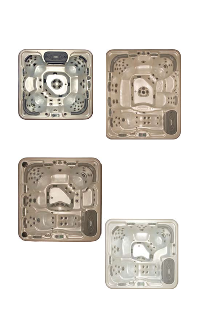
This manual covers the following spas
PIPER GLEN
DOVE CANYON
PELICAN BAY
QUAIL RIDGE

TABLE OF CONTENTS
Congratulations..............................................................
Safety Warnings..............................................................
Line Drawing Key...........................................................
Spa Conguration and Water Capacities.....................
Electrical Requirements and Installation.....................
60 Hz Electrical Wiring...........................................
50 Hz Electrical Wiring...........................................
Spa Start Up....................................................................
Selecting a Location..............................................
Inspection..............................................................
Filling the Spa with Water......................................
Turning the Power On............................................
Verifying Water Circulation.....................................
Testing the GFCI Breaker......................................
Priming the Pump..................................................
Water Preparation.................................................
in.XM Controller Diagram......................................
Icon Introduction.............................................................
Spa Functions ................................................................
Standby Key..........................................................
Pump Keys............................................................
Light Key................................................................
Basic Programming........................................................
Program Key..........................................................
Setting the Time.....................................................
Setting Filter Cycle Start Time...............................
Setting Filter Cycle Duration..................................
Filter Cycle Frequency...........................................
Setting Economy Mode.........................................
Setting Economy Start Time..................................
Setting Economy End Time...................................
Setting Temperature Unit.......................................
Water Temperature Regulation..............................
Cool Down.............................................................
Smart Winter Mode................................................
1
3
5
6
10
11
13
16
16
17
17
19
19
19
20
20
21
22
23
25
25
26
27
27
27
27
27
28
28
28
28
29
29
29
29

TABLE OF CONTENTS cont....
Maintaining Your Spa...............................................
Draining Your Spa............................................
Pillow Care......................................................
Jet Care...........................................................
Removing, Installing, and Cleaning Filters......
Winterizing Your Spa.......................................
Replacing the Light Bulb..................................
Spa Cabinet Care............................................
Cleaning Your Spa Interior...............................
Cover Care......................................................
Chemical Treatment of Water..........................
Water Chemistry........................................................
Water Treatment Glossary...............................
Spa Chemicals Glossary..........................................
Maintaining the Proper pH...............................
Troubleshooting........................................................
Warranty Information...............................................
Interior Spa Diagram................................................
30
30
30
31
32
33
33
34
34
35
36
37
37
42
43
44
51
57

Congratulations...
Congratulations on the purchase of your new Platinum Elite spa
by Artesian. We know you will enjoy your spa. Although spas are
relaxing and fun, we believe they can be an indispensable part
of a healthy lifestyle. The spa lifestyle is one that encourages
health and well-being.
Owning a spa brings some responsibility. With proper care, your
spa will provide years of enjoyment and therapy for your family
and friends. Please take time to read and understand all of the
instructions provided before you install your Artesian spa. This
owner’s manual is meant to be a supplement to the training you
should receive from your dealer when you purchase and start up
your spa for the rst time.
Please remember your spa is a powerful piece of electrical
equipment. It is extremely important that you have it properly
installed to ensure safe use. This manual explains safety
precautions, installation instructions, and operating and
maintenance procedures. If you have any questions regarding
this manual, please call your competent Artesian spa dealer,
who will be happy to further assist you.
Before you do anything else, make sure you
visit our website at www.artesianspas.com and
register your new Artesian spa.
1
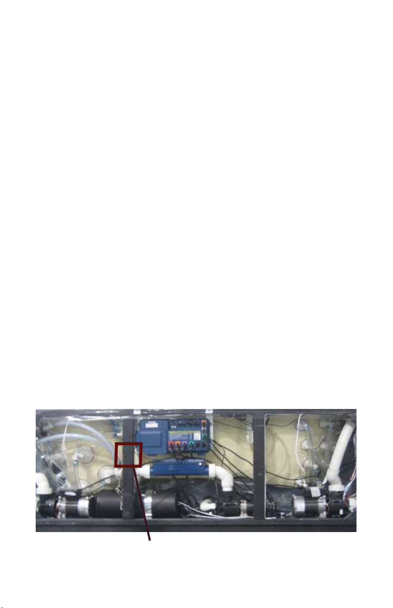
For your future reference and convenience, please record the Serial and Model number along with the installation date in the spaces
provided below. STORE THIS MANUAL WHERE YOU CAN EAS-
ILY FIND IT WHEN NEEDED. The serial and model numbers are
mounted on the base of the equipment enclosure area, as shown
below.
Spa Serial Number_____________________________________
Spa Model Number_____________________________________
Spa Installation Date____________________________________
Dealer Name, Address, and Telephone Number
____________________________________________________
____________________________________________________
____________________________________________________
Diagram of Where to Find Serial Number
Serial Number Information
2

SAFETY WARNINGS
PLEASE TAKE THE TIME TO READ ALL OF THESE WARNINGS AND
CAUTIONS PRIOR TO USING YOUR SPA
PLEASE, be a responsible spa owner. When installing and using this
spa, always adhere to basic safety precautions. Be sure to list emergency
telephone numbers at the telephone nearest the spa, including physician,
hospital, ambulance, police, and the re department. Be certain to explain
safety precautions to all new or occasional users of your spa. Remember,
they may not be aware of the possible risks associated with the spa water
temperature.
Have at least one family member learn CPR (cardiopulmonary resuscitation). IT COULD SAVE A LIFE!
1. READ AND FOLLOW ALL INSTRUCTIONS!
2. WARNING - To reduce the risk of injury, do not permit children to use
this product unless they are closely supervised at all times.
3. A wire connector is provided on this unit to connect a minimum 8 AWG
(8.4 mm ) solid copper conductor between this unit and any metal
equipment, metal enclosures of electrical equipment, metal water pipe, or
conduit within 5 feet (1.5 m) of the unit.
4. DANGER - Risk of Accidental Drowning - Extreme caution must be
exercised to prevent unauthorized access by children. To avoid accidents,
ensure that children cannot use this spa unless they are supervised at all
times.
5. DANGER - Risk of Injury - The suction ttings in this area are sized
to match the specic water ow created by the pump. Should the need
arise to replace the suction ttings or the pump, be sure the ow rates are
compatible.
Never operate spa if the suction ttings are broken or missing. Never replace a suction tting with one rated less than the ow rate marked on the
original suction tting.
6. DANGER - Risk of Electrical Shock - Install at least 5 feet (1.5 m) from
all metal surfaces. As an alternative, a spa may be within 5 feet of metal
surfaces if each metal surface is permanently connected by a minimum 8
AWG (8.4 mm ) solid copper conductor to the wire connector on the terminal box that is provided for this purpose.
7. DANGER - Risk of Electric Shock - Do not permit any electrical appli-
ance such as a light, telephone, radio, or television, within 5 feet (1.5 m)
of a spa.
3

SAFETY WARNINGS cont...
8. WARNING - To reduce the risk of injury:
a) The water in a spa should never exceed 40ºC (104ºF). Water temperatures between 38ºC (100ºF) and 40ºC are considered safe for a healthy
adult. Lower water temperatures are recommended for young children
and when spa use exceeds 10 minutes.
b) Since excessive water temperatures have a high potential for causing
fetal damage during the early months of pregnancy, pregnant or possibly
pregnant women should limit spa water temperatures to 38ºC (100ºF).
c) Before entering a spa, the user should measure the water temperature
with an accurate thermometer since the tolerance of water temperature
regulating devices varies.
d) The use of alcohol, drugs, or medication before or during spa use may
lead to unconsciousness with the possibility of drowning.
e) Obese persons and persons with a history of heart disease, low or high
blood pressure, circulatory system problems, or diabetes should consult a
physician before using a spa.
f) Persons using medication should consult a physician before using a
spa since some medication may induce drowsiness while other medication may affect heart rate, blood pressure, and circulation.
AUDIO COMPONENT WARNINGS
Spas equipped with the Audio system should follow these guidelines for safety:
1. CAUTION - Risk of Electrical Shock - Do not leave compartment door
open.
2. CAUTION - Risk of Electrical Shock - Replace components only with
identical components.
3. Do not operate the audio controls while inside the spa.
4. WARNING - Prevent Electrocution - Do not connect any auxiliary
components (for example cable, additional speakers, headphones, additional audio/video components, etc.) to the system.
5. These units are not provided with an outdoor antennae; when provided,
it should be installed in accordance with Article 810 of the National Electrical Code, ANSI/NFPA 70.
4
6. Do not service this product yourself as opening or removing covers
may expose you to dangerous voltage or other risk of injury. Refer all ser-
vicing to qualied service personnel.
KEEP THESE SAFETY INSTRUCTIONS IN A CONVENIENT AND
READILY ACCESSIBLE LOCATION!!
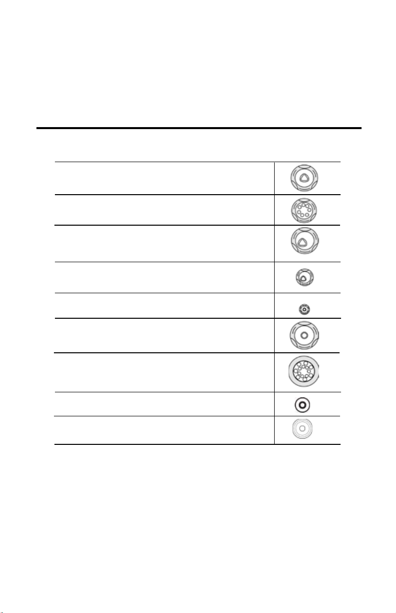
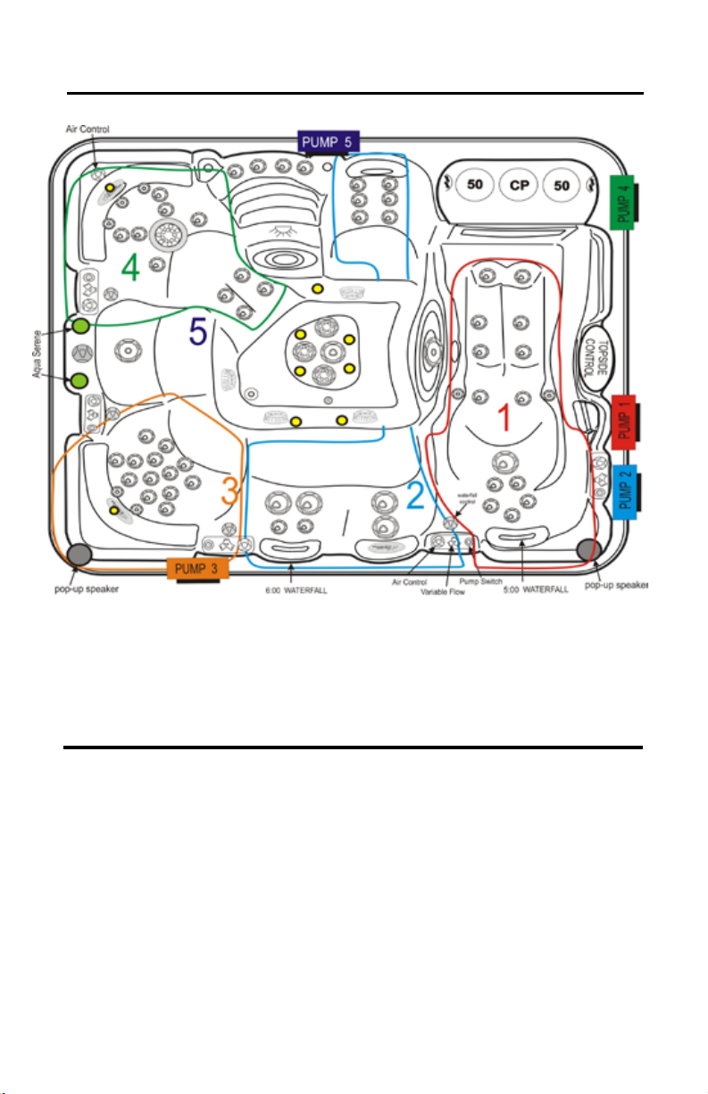
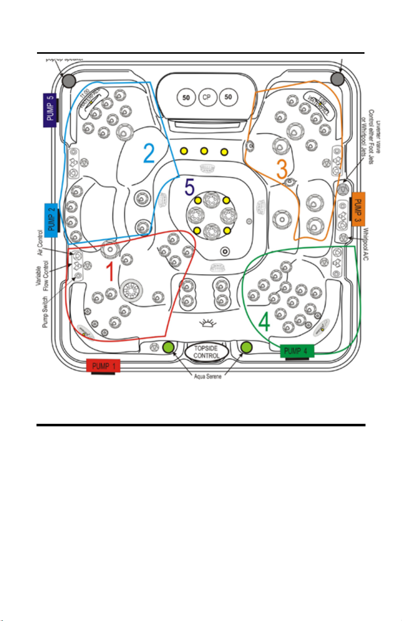
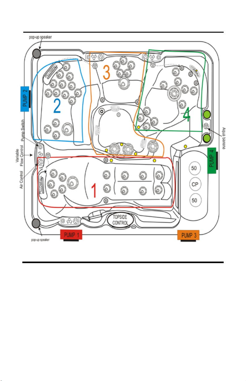
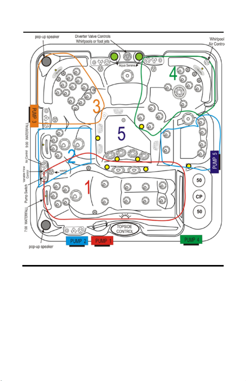
LINE DRAWING KEY
Name of Component
5” Helix DIirect W / ESC
5” Helix MSSG W / ESC
5” Helix Roto W / ESC
3” Helix Roto W /ESC
2” Helix Direct
Helix Whirlpool
7” Jumbo Storm Massage W / ESC
Jet Floor Sweeper
Ozone / Drain Jet SS
Symbol for Component
Line Drawings may not be exact models of your particular spa.
Certain options may be shown that are not included on your spa.
5
SPA CONFIGURATION AND WATER CAPACITY
PELICAN BAY
Volume 550 gal 2082 l
Weight (dry/lled) 1170/5755 lbs 531/2610 kg
Dimensions 108x92x37in 274x234x94 cm
Control in.XM in.XM
Heater 4kW in.THERM 3.6kW in.THERM
Circulation System Laing Hi-Flo Laing Hi-Flo
Ozone CD CD
Cartridge Filter 2 2
Disposable Filter 1 1
6” Waterfall 2 2
6
SPA CONFIGURATION AND WATER CAPACITY
PIPER GLEN
Volume 505 gal 1514 l
Weight (dry/lled) 1120/5330 lbs 508/2418 kg
Dimensions 92x92x37in 234x234x94 cm
Control in.XM in.XM
Heater 4kW in.THERM 3.6kW in.THERM
Circulation System Laing Hi-Flo Laing Hi-Flo
Ozone in.Zone, CD in.Zone, CD
Cartridge Filter 2 2
Disposable Filter 1 1
6” Waterfall 2 2
7
SPA CONFIGURATION AND WATER CAPACITY
QUAIL RIDGE
Volume 345 gal 1174 l
Weight (dry/lled) 900/3776 lbs 408/1713 kg
Dimensions 92x79x34in 234x196x86 cm
Control in.XM in.XM
Heater 4kW in.THERM 3.6kW in.THERM
Circulation System Laing Hi-Flo Laing Hi-Flo
Ozone CD CD
Cartridge Filter 2 2
Disposable Filter 1 1
6” Waterfall 2 2
8
SPA CONFIGURATION AND WATER CAPACITY
DOVE CANYON
Volume 475 gal 1514 l
Weight (dry/lled) 1050/5010 lbs 476/2272 kg
Dimensions 92x92x37in 234x234x94 cm
Control in.XM in.XM
Heater 4kW in.THERM 3.6kW in.THERM
Circulation System Laing Hi-Flo Laing Hi-Flo
Ozone CD CD
Cartridge Filter 2 2
Disposable Filter 1 1
6” Waterfall 2 2
9

ELECTRICAL REQUIREMENTS
AND INSTALLATION
The following information is provided for hooking up electrical supply to
your new spa. A qualied, licensed, electrician must perform this work.
Failure to follow these instructions will terminate all warranty coverage
and can cause serious injury or death.
Your 60 Hz Artesian spa is preset at the factory to run on 240V with a
48 amp input. This feature gives you the most performance out of your
spa. This will require a 240V, 60-amp GFCI If a 60-amp service is not
available, your spa can be made to run with 32 or 40 amps input rating.
Press the SELECT key on the spa control pack to change the input rating.
Your export 50 Hz Artesian spa is preset out of factory to run 230V240V 3 wires 30 amp max input. This product must always be connected to residual current device (RCD) having a trip current of not more
than 30 mA.
ELECTRICAL WIRING
WARNING: Your spa must be wired by a certied electrician and
according to these instructions. Failure to do so will terminate all
warranties and all listings from the independent listing facility.
1) The Platinum Elite Class Spa requires a 240 VAC dedicated system.
The spa must be hard wired to the power supply, with no plug-in connections, extension cords, or sharing of service.
2) The spa requires that you run 6 (10 mm²) or 8 (8.4 mm²) AWG copper
wire, depending on the GFCI size. Do Not Use Aluminum Wire.
3) The power supply must have a suitable Ground Fault Circuit Interrupter (GFCI), according to Section 422-20 of the National Electrical
Code, ANSI/NFPA 70-7987 or other national installation requirement
with a residual current device (RCD) having a trip current of not more
than 30 mA. This could be used as the shut-off switch, which must be
installed in plain view of the spa. This electrical service must be readily
accessible to the spa occupants, but must not be within 5 feet of the
spa.
4) Use only non-metallic conduit and ttings when installing power to
the spa.
5) After your spa has been positioned, route lines through the knockout
on the left or right front corner of the spa.
6) Connect the power to the spa.
10
50Hz Electrical Wiring Diagram
Pack Terminal Block from GFCI
MUST BE DONE BY A CERTIFIED ELECTRICIAN
1) The black and red wires from the main electrical box* must be connected to the input lugs in the GFCI.
2) The white wire from the main electrical box* must be connected to the
dedicated neutral bar inside the GFCI box.
3) The green or copper wire from the main electrical box* must be connected to a separate dedicated ground bar inside the GFCI box.
4) The red and white wires from the spa connect to the GFCI breaker
output terminals.
5) The white wire from the spa must connect to the center load terminal
ON THE GFCI BREAKER, usually behind the white pig-tail on the breaker
itself
6) The white pig-tail from the GFCI breaker must connect to the dedicated
ground bus inside the GFCI breaker box.
7) The green or copper wire from the spa must connect to the dedicated
ground bus inside the GFCI box.
*Main electrical box refers to the house distribution panel and not the
GFCI
11
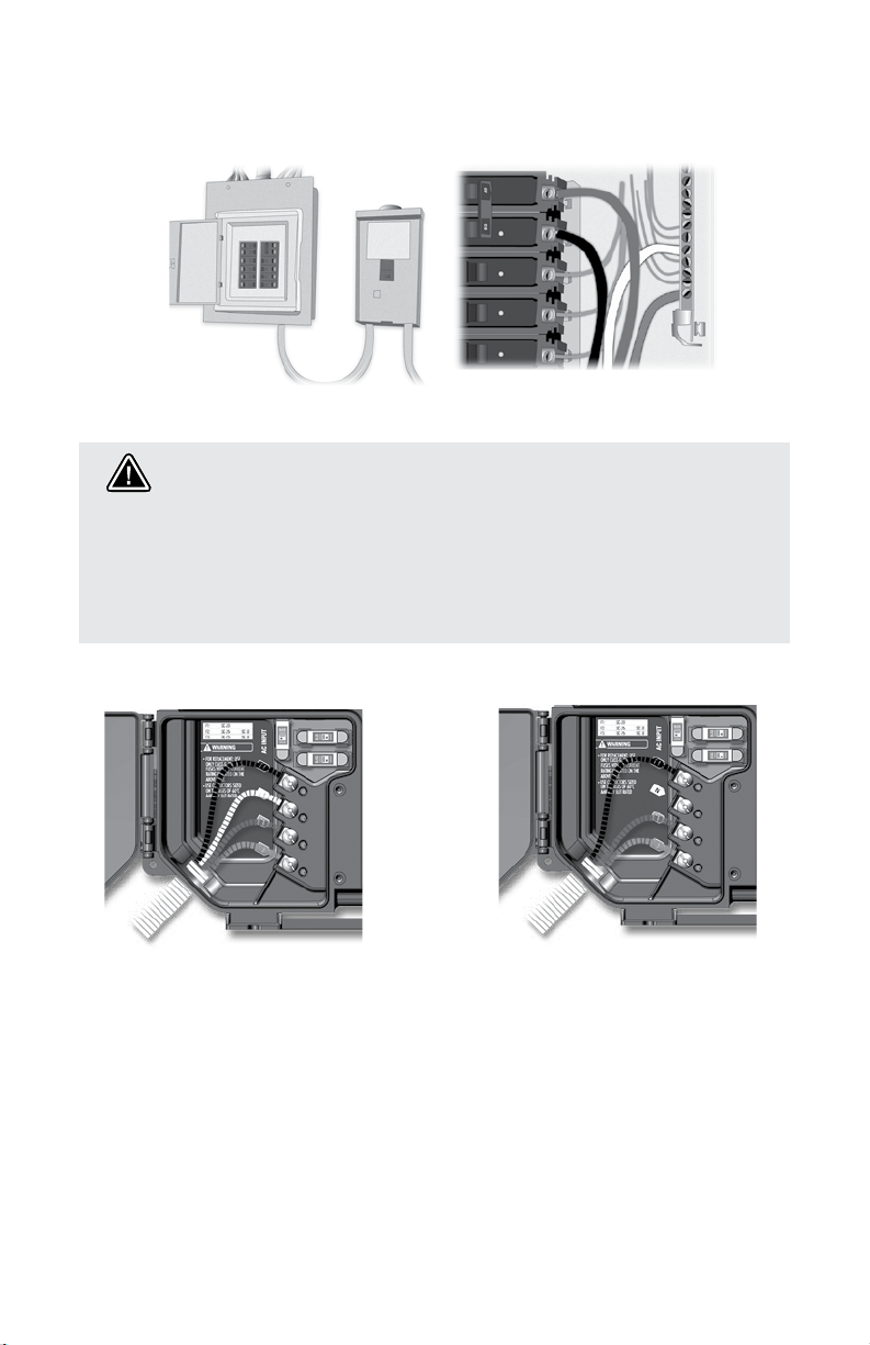
Electrical wiring
Main electrical box GFCI panel
Warning!
"For units for use in other than single-family dwellings, a clearly labeled
emergency switch shall be provided as part of the installation. The switch
shall be readily accessible to the occupants and shall be installed at least
5 feet (1.52 m) away, adjacent to, and within sight of the unit".
For 240 VAC (4 wires)
Correct wiring of the
electrical service box,
GFCI, and pack terminal
block is essential.
Call an electrician if
necessary.
12
For 240 VAC (*3 wires)
*If connected to a 3 wire
system (without neutral), all
120 VAC components will
not work.
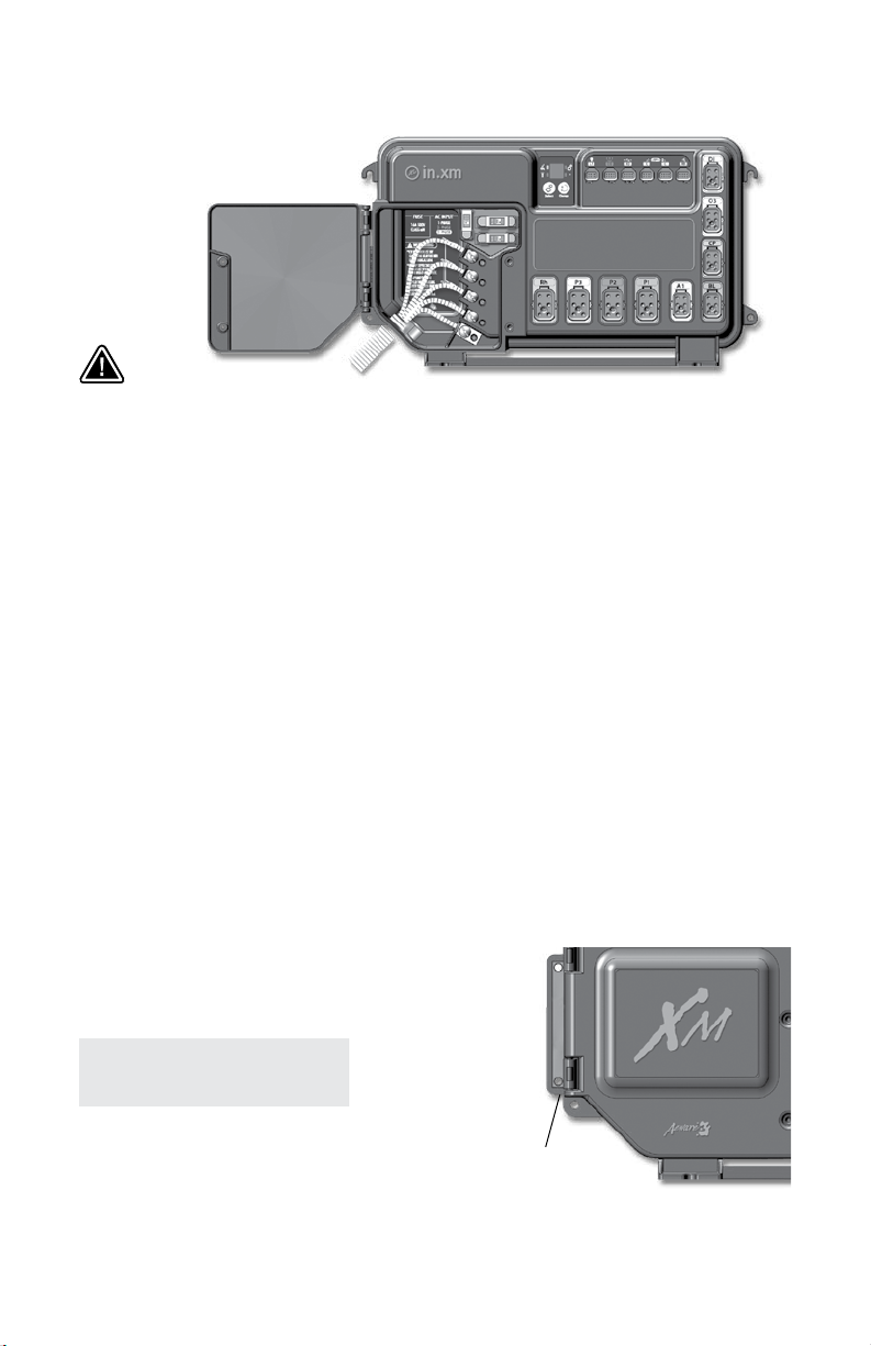
Electrical wiring 50 Hz
Warning!
This product must always be connected to a circuit protected by a residual-current
device (RCD) having a rated operating residual-current not exceeding 30 mA.
Proper wiring of the electrical service box, RCD and in.xm.ce terminal block is
essential!
Check your electrical code for local regulations. Only copper wire should be used,
never aluminum.
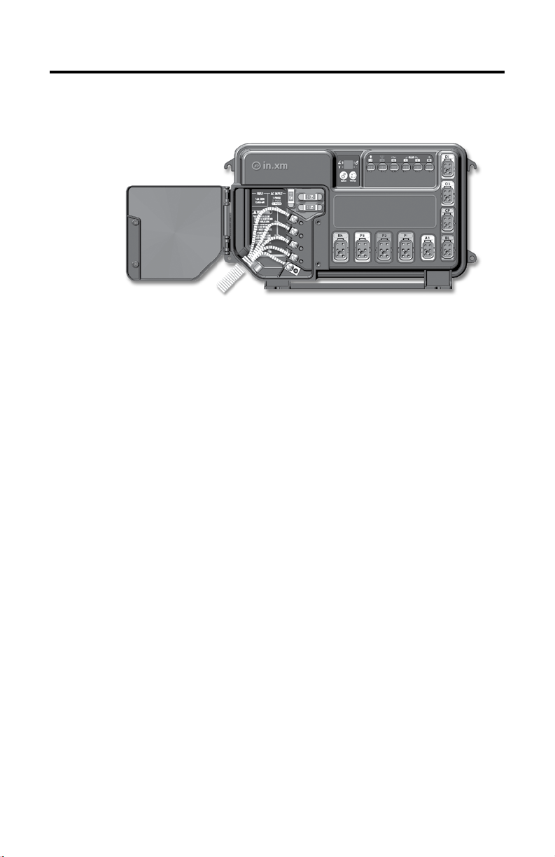
To install the wiring for the in.xm.ce spa control, you'll need a Phillips screwdriver, a 14
mm (9/16") nut driver or a at screw-driver. Loosen the 2 screws of the spa pack door
and open it. Remove 200 mm (8") of cable insulation. Strip away 25 mm (1") of each
wire insulation. Pull the cable through the cutout of the box and use an IEC certied
plastic bushing that will maintain the IPX5 rating. Also, the power cord must be in
accordance with the national electrical code of the country in which it's to be installed
and must maintain IPX5 rating. Make sure that only the uncut sheathing is clamped
at this opening. Push the color-coded wires into the terminals as indicated on the
sticker, use the 14 mm (9/16") wrench or at screwdriver to tighten the bolts on the
terminals. After making sure wire connections are secure, push them back into the
box and close the door. Tighten the 2 screws of the spa pack door.
Connect the bonding conductor
to the bonding lug on thel eft side of the in.xm.ce spa
pack (a grounded electrode conductor shall be used
to connect the equipment grounding conductors).
Important!
CE and UL /CSA parts are
not interchangeable!
This note applies to all in.xm.ce spa packs, in.therm.
ce heating systems & in.link connectors.
Bonding lug
13
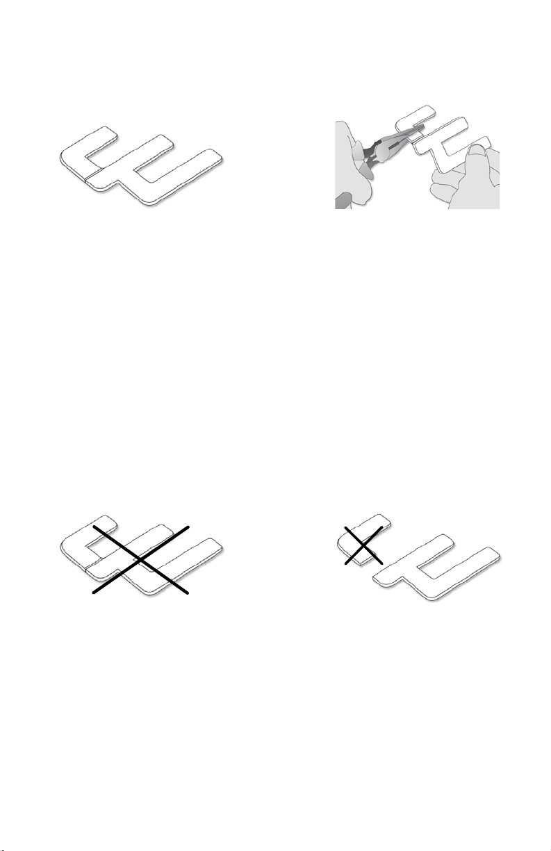
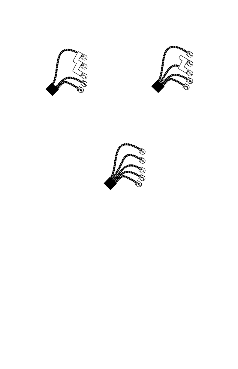
Electrical wiring 50 Hz
Case 1
The installation of electrical
circuit jumpers is needed
in certain input supply
congurations.
Use uncut jumper as supplied
in the case of an input supply
wiring, single-phase 1 x 230
VAC (32 A max).
Case 3
Case 2
In the case of an input supply
wiring for a dual phase system
2 x 230 VAC (16 A max), you'll
need to cut off a portion of the
jumper piece.
Proceed as follows:
Use a pair of pliers to rmly
hold the upper half of the metal
jumper, then break off the
other half.
Important!
Please note that in a 3-phase
system 1 x 230 VAC (3 x 16A)
No jumper installation
is required.
14
Safely dispose of the discarded
portion in accordance with the
local waste disposal legislation
in force.
'2/5.$
,).%
.%542!,
,).%
,).%
.%542!,
'2/5.$
,).%
,).%
,).%
.%542!,
'2/5.$
Electrical wiring 50 Hz
1 x 230 VAC (1 x 32A) Single-phase
1 x 230 VAC (2 x 16A) Dual-phase*
1 x 230 VAC (3 x 16A) Three-phase
An IEC certied bushing that will maintain the IPX5 rating must be used. The power
cord must be in accordance with the national electrical code of the country in which
the in.xm.ce is to be installed.
*Dual-phase system: two electrical phases out of a three-phase power system. It's
important to note that on a polyphase power system, all electrical phases must share
the same neutral.
15
 Loading...