

Page 1
®
ENGINEERING COMPANY INC.
51 Winthrop Road
Chester, Connecticut 06412-0684
Phone: (860) 526-9504
Universal Mounting Bracket
SA314 / SA315 Siren Speaker
Installation Guide:
Fax: (860) 526-4078
Internet: www.whelen.com
Sales e-mail: autosale@whelen.com
Canadian Sales e-mail: autocan@whelen.com
Customer Service e-mail: custserv@whelen.com
DANGER! Sirens produces extremely loud emergency warning tones! Exposure to these
tones without proper and adequate hearing protection, could cause ear damage and/or hearing
loss! The Occupational Safety & Health Administration (www.osha.gov) provides information
necessary to determine safe exposure times in Occupational Noise Exposure Section 1910.95.
Until you have determined the safe exposure times for your specific application, operators and
anyone else in the immediate vicinity should be required to wear an approved hearing protection
device. FAILURE TO FOLLOW THIS RECOMMENDATION COULD CAUSE HEARING LOSS!
Safety First
This document provides all the necessary information to allow your Whelen product to be properly and safely installed.
Before beginning the installation and/or operation of your new product, the installation technician and operator must
read this manual completely. Important information is contained herein that could prevent serious injury or damage.
• Proper installation of this product requires the installer to have a good understanding of automotive electronics,
systems and procedures.
• If mounting this product requires drilling holes, the installer MUST be sure that no vehicle components or other
vital parts could be damaged by the drilling process. Check both sides of the mounting surface before drilling
begins. Also de-burr any holes and remove any metal shards or remnants. Install grommets into all wire
passage holes.
• If this manual states that this product may be mounted with suction cups, magnets, tape or Velcro™, clean the
mounting surface with a 50/50 mix of isopropyl alcohol and water and dry thoroughly.
• Do not install this product or route any wires in the deployment area of your air bag. Equipment mounted or
located in the air bag deployment area will damage or reduce the effectiveness of the air bag, or become a
projectile that could cause serious personal injury or death. Refer to your vehicle owners manual for the air bag
deployment area. The User/Installer assumes full responsibility to determine proper mounting location, based
on providing ultimate safety to all passengers inside the vehicle.
• For this product to operate at optimum efficiency, a good electrical connection to chassis ground must be
made. The recommended procedure requires the product ground wire to be connected directly to the NEGATIVE
(-) battery post.
• If this product uses a remote device to activate or control this product, make sure this control is located in an
area that allows both the vehicle and the control to be operated safely in any driving condition. DO NOT
ATTEMPT TO ACTIVATE OR CONTROL THIS DEVICE IN A HAZARDOUS DRIVING SITUATION.
• It is recommended that these instructions be stored in a safe place and
referred to when performing maintenance and/or reinstallation of this
product.
• FAILURE TO FOLLOW THESE SAFETY PRECAUTIONS AND
INSTRUCTIONS COULD RESULT IN DAMAGE TO THE PRODUCT OR
VEHICLE AND/OR SERIOUS INJURY TO YOU AND YOUR PASSENGERS!
ACTIVATION OF THIS
SIREN MAY DAMAGE
UNPROTECTED EARS!
CAUTION
Loud siren noise can cause
hearing damage and/or loss.
Wear
Refer to OSHA Section 1910.95 prior
Protection!
to putting ANY siren into service!
Automotive: Sirens/Switches
For warranty information regarding this product, visit www.whelen.com/warranty
©1999 Whelen Engineering Company Inc.
Form No.13497J (050208)
Page 1
Page 2
wire
exit
&
drain
hole
Selecting a Mounting Location: The mounting location should not only be as
flat as possible but also allow the speaker to project its tone parallel with the road.
For specific applications for the universal bracket, refer to the following pages.
Installation:
1. Position the bracket onto the desired mounting area and mark off the
mounting holes using the bracket as a template.
2. In the center of the 4 holes you marked off, drill a 1/8 inch pilot hole into the
mounting surface for each of the mounting screws then enlarge the pilot
holes with a 9/32 inch drill. If you can get access to the other side of the
mounting area, and it is not too thick, you may want to substitute the
mounting screws with nuts, bolts and washers (customer supplied) of
comparable strength and thickness.
3. Secure the bracket onto the mounting surface with the supplied mounting
hardware. NOTE: You may need a socket and drill to drive the screws.
4. Attach speaker to bracket with the supplied mounting hardware then extend
the WHITE (Positive) and BLACK (Negative) speaker wires to your amplifier
and connect as shown in the amplifiers instructions.
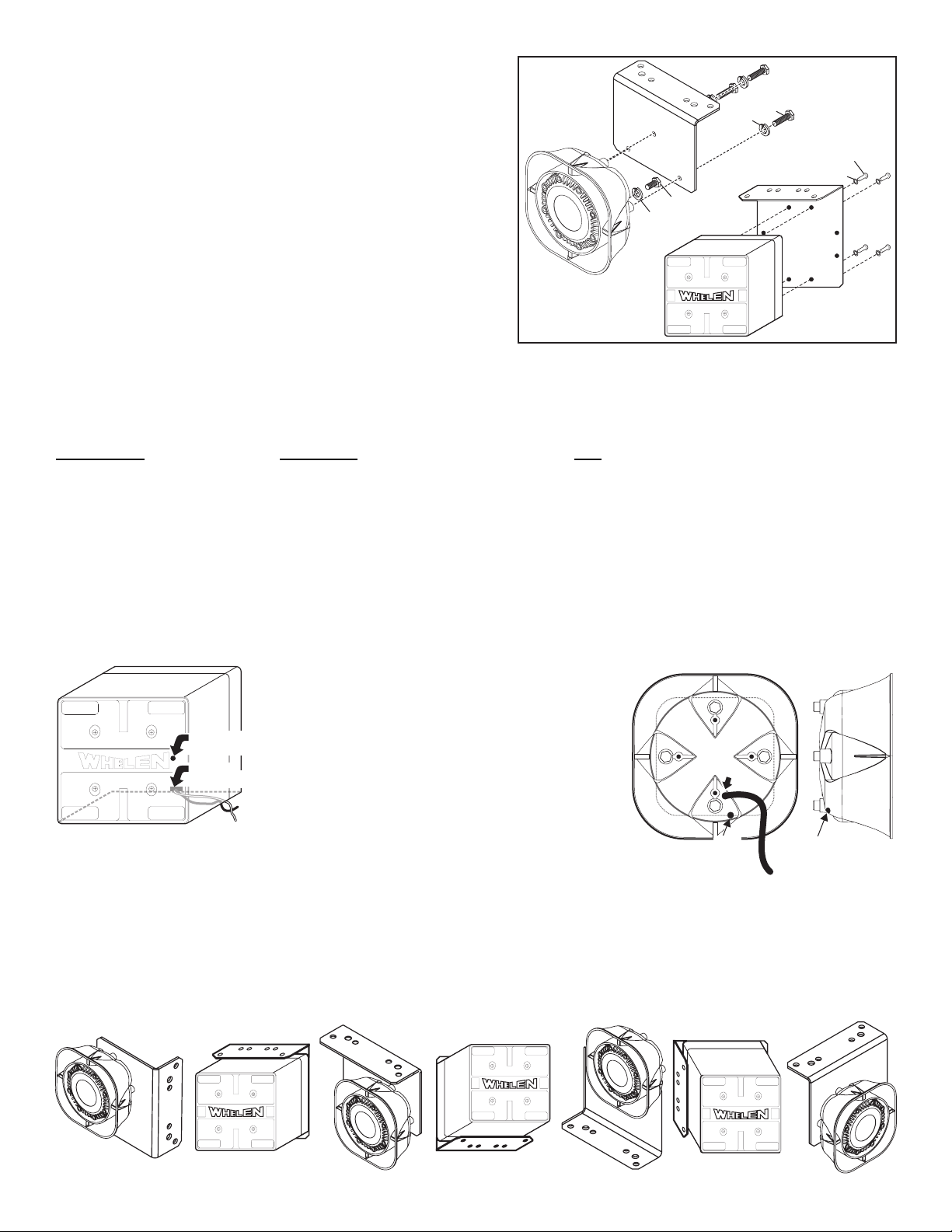
Mounting
the Speaker
1/4 - 20 X 1-1/2"
HEX HEAD SS
1/4" SPLIT
LOCK WASHER
SA315
1/4 X 20 X 1-1/4
HEX HEAD
1/4" SPLIT
LOCK WASHER
SA314
IMPORTANT: It is the responsibility of the installation technician
to make sure that the installation and operation of this product
will not interfere with or compromise the operation or efficiency
of any vehicle equipment!
to Bracket
#14 X 1" PPHSMS
1/4" INTERNAL TOOTH
LOCKWASHER
APPLICATION HARDWARE QTY
2004-05 DURANGO . . . . . . . . . . . . . . . . . . . . NUT: 5/16-18 Hex SS 1/2" Diameter . . . . . . . . . . . . . . . . . . . . . . . . 2
2004-05 DURANGO . . . . . . . . . . . . . . . . . . . BOLT: 5/16-18 X 1 Hex Head SS . . . . . . . . . . . . . . . . . . . . . . . . . .2
2004-05 DURANGO . . . . . . . . . . . . . . . . . . . . WASHER: 5/16 Split Lock. . . . . . . . . . . . . . . . . . . . . . . . . . . . . . . .2
2001 TAURUS . . . . . . . . . . . . . . . . . . . . . . . . SCREW: 1/4 X 1" Hex Washer Head Self Drilling . . . . . . . . . . . . . 4
For Any Application / Bracket to vehicle . . SCREW: 5/16 X 1" Hex Head SMS SS . . . . . . . . . . . . . . . . . . . . . 4
For Any Application / Bracket to vehicle . . WASHER: 5/16" Flat SS 3/4" Outer Diameter . . . . . . . . . . . . . . . .2
Mounting SA314 Speaker To Bracket . . . . . SCREW: 14 X 1 PPHSMS A Point . . . . . . . . . . . . . . . . . . . . . . . . . 4
Mounting SA314 Speaker To Bracket . . . . . WASHER: 1/4 Internal Tooth Lock . . . . . . . . . . . . . . . . . . . . . . . . .4
Mounting SA315 Speaker to Bracket . . . . . SCREW: 1/4-20 X 1-1/2 Hex Head SS. . . . . . . . . . . . . . . . . . . . . . 3
Mounting SA315 Siren Driver to Housing. . BOLT: 1/4 X 20 X 1-1/4 Hex Head . . . . . . . . . . . . . . . . . . . . . . . . . 1
Mounting SA315 Speaker to Bracket . . . . . WASHER: 1/4 Split Lock Washer . . . . . . . . . . . . . . . . . . . . . . . . . .4
SA314
WARNING: Speaker wires must exit the bottom of the speaker.
The wire hole also serves as a drainage hole. Improper mount-
The SA315 siren speaker mounting kit comes with
3 long bolts (1/4-20 X 1-1/2” Hex Head SS). The
longer bolts are necessary to go through the
mounting bracket, through the siren housing and
into the siren driver. They will replace 3 of the 4
shorter bolts (“A”) that now secure the siren driver
to the speaker housing. Your speaker is shipped
with 2 or more of the shorter bolts installed. A short
bolt must be used in the hole that does not go
through the bracket so it will properly secure the
driver to the housing. If you need to remove all 4
bolts at once be sure to hold the driver in place.
SA315 / Rear View
Side View
ing will result in siren driver failure and void the siren warranty.
IMPORTANT NOTE: In most applications the existing drain hole
will work fine. However, since this mounting bracket can mount
NEW DRAIN
HOLE HERE
EXISTING
DRAIN HOLE
in a variety of positions the drain hole in the bottom of the
speaker can be ineffective if the speaker is mounted with the
drain hole facing to the side. If your application does not allow
this an alternate drain hole may be drilled.
wire
wire
exit &
exit &
drain
drain
hole
hole
Drilling a drain hole / SA314: Drill a small drainage hole in the
area indicated, using a 1/8” (.125) drill bit. There is a second wall
behind the outer surface that you must not drill through. Use a drill
stop set to a 1/4” depth. This will insure that you don’t hit any internal speaker parts while drilling the hole.
New
drain
hole
New
drain
hole
Drilling a drain hole / SA315: Remove the bolts that hold the driver to the speaker body and slide
the driver out. Drill a small drainage hole in the rear of the speaker as shown. The hole should be drilled in the rear, on the curved part of the speaker body
(See side view) using a 1/8” drill bit. Make sure the hole is located on the bottom (depending on the position the speaker will be in after mounting). Be sure
you drill through both the outer and inner walls of the siren housing so the drain hole will reach the driver compartment. Reassemble the speaker, reinstalling
the driver into the speaker body and securing the driver with the bolts you removed. WARNING: When you are reassembling the speaker, be very
careful not to pinch the wires between the siren driver and the housing. Feed the wires through the wire hole first.
Possible Mounting Positions: The SA314 or SA315 can mount to the universal bracket in a variety of positions depending on what your mounting
requirements are. The only necessity is that the speaker wires exit the bottom, (toward the ground) since this hole also serves as the drainage
hole for the speaker.
Page 2
Page 3

Installation / 2001 Ford Taurus:
READ BEFORE INSTALLING: The speaker will mount in the area
usually occupied by the air bag system. If your vehicle is equipped
with A.B.S. you can not mount the speaker in this location.
For this appication, the speaker will mount under the battery tray. First you
will need to remove the battery and tray, and the air filter and housing (Fig.
2). The speaker bracket will mount to the drivers side of the engine
compartment, on the side wall.
1. Disconnect the ground on the battery, remove the battery and tray
and then remove the air filter and housing.
2. Attach the speaker to the bracket (Fig. 1). An SA314 is shown. See
page 2 for an SA315.
3. Position the bracket (with speaker) onto the mounting area. Do not
position it so far forward that the speaker is muffled. Be sure the
bracket doesn’t interfere with any existing vehicle components. Using
the bracket as a template, mark the mounting surface where the
mounting screws will be located.
Note: Do not allow the new mounting hole locations to be directly
adjacent to any existing holes.
4. Remove the speaker from the bracket. Using the self-tapping screws
and washers supplied, mount the bracket onto the vehicle.
Note: You will need to drive the self tapping screws in with a socket
attached to a drill.
5. Remount the speaker to the bracket making sure that the speaker
wires exit the bottom for proper drainage .
6. Extend the WHITE (Positive) and BLACK (Negative) speaker wires to
your siren amplifier and connect as shown in the amplifiers
instructions.
Fig. 1
Fig. 2 Mounting area shown with
Battery and tray plus air filter and
filter housing removed. The siren
will mount in this area.
Installation / 2004-05 Dodge Durango:
1. First you will have to remove the grill. To remove the grill, you first
have to remove both headlight assemblies. Refer to your vehicle
owners manual for the proper procedure for both.
2. The speaker bracket will mount to the side of the support brace (on
the passenger side) that is indicated in Figure 1 below.
3. Place the bracket onto the mounting area in the exact position it will
be mounted, then using the bracket as a template mark the 2
mounting holes off onto the mounting surface.
DRIVERS SIDE
Fig. 3
Mark location of
the top edge of
the bracket.
The top view of the bracket
shows which holes to use
FRONT OF VEHICLE
4. Secure the speaker to the mounting bracket. . An SA314 is shown.
See page 2 for an SA315.
5. Drill the 2 mounting holes using a drill bit sized for a 5/16 - 18 hex
head bolt and secure the bracket (with speaker) onto the mounting
area with the supplied mounting hardware.
6. Extend the WHITE (Positive) and BLACK (Negative) speaker wires to
your siren amplifier and connect as shown in the amplifiers
instructions.
FIG. 2
for this application
MOUNTING
AREA
FIG. 1
Page 3
5/16 - 18
1/2" DIA.
HEX NUT
5/16 SPLIT
LOCK
WASHER
Use these
holes for this
application.
5/16 - 18 X 1
HEX HEAD BOLT
Page 4

Air
Conditioner
Condensor
Mounting
screws
Mounting: / 2002 - 2003 Ford Explorer: The speaker will be located in front of the driver side front tire, behind the bumper. You will use two existing
nuts and their bolts that are already on the vehicle. Always be sure that the speaker wires exit the bottom after mounting for proper drainage.
1. Secure the bracket to the speaker using the supplied mounting hardware (See hardware applications on page 2). An SA314 is shown in Fig. 1.
Refer to page 2 for the SA315. Be sure you mount the SA315 onto the bracket in the same position the SA314 is shown here.
2. Looking in through the drivers side wheel well, find the 2 existing bolts on the vehicle that match up to the brackets mounting holes.
3. Remove the 2 nuts from their bolts and mount the bracket (with speaker) securing it with the 2 nuts you removed (Figs. 2A & 2B).
4. Extend the WHITE (+) and BLACK (-) speaker wires to your siren amplifier and connect as shown in the amplifier instructions.
Fig. 1 Mount Siren to Bracket
L
L
FRONT OF VEHICLE
E
W
L
E
E
H
W
Top view of bracket
shows which holes
fit this application
FRONT OF VEHICLE
SA314
SIREN
SA314
SIREN
Fig. 2A
Fig. 2B
Mounting: 2003 Suburban / Tahoe: The siren will mount in front of the vehicles gravel shield, just forward of (and below) the air
conditioner condenser as shown (Figs. 2 & 3). Always be sure that the sirens wires exit the bottom of the siren after mounting for proper
drainage of the siren.
1. Place the bracket onto the mounting surface and mark off the location of the mounting holes.
2. Remove the bracket and drill the mounting holes an appropriate size for the supplied mounting hardware (See hardware applications on page 2).
3. Secure the bracket to the speaker using the mounting hardware provided for your model speaker. An SA314 is shown. See page 2 for an SA315.
4. Secure the bracket (with speaker) to the mounting location with the supplied mounting hardware.
5. Extend the WHITE (+) and BLACK (-) speaker wires to your siren amplifier and connect as shown in the amplifiers instructions.
Top view of bracket
shows which holes
fit this application
Siren attaches to
bracket as shown
Mounting
Mounting
screws
Screws
FIG. 2FIG. 1
Air Conditioner
Air Conditioner
Condensor
Condenser
b
b
e
u
R
r
C
o
v
e
FIG. 3
Gravel
Shield
Gravel Shield
Front Bumper
r
Page 4
 Loading...