

Page 1

®
ENGINEERING COMPANY INC.
51 Winthrop Road
Chester, Connecticut 06412-0684
Phone: (860) 526-9504
Models: RFCF85, RFNF85
Installation Guide:
LED Traffic Advisor™
Fax: (860) 526-4078
Internet: www.whelen.com
Sales e-mail: autosale@whelen.com
Canadian Sales e-mail: canadiansales@whelen.com
Customer Service e-mail: custserv@whelen.com
Safety First
This document provides all the necessary information to allow your Whelen product to be properly and safely installed.
Before beginning the installation and/or operation of your new product, the installation technician and operator must
read this manual completely. Important information is contained herein that could prevent serious injury or damage.
• Proper installation of this product requires the installer to have a good understanding of automotive electronics,
systems and procedures.
• Failure to use specified installation parts and/or hardware will void the product warranty!
• If mounting this product requires drilling holes, the installer MUST be sure that no vehicle components or other
vital parts could be damaged by the drilling process. Check both sides of the mounting surface before drilling
begins. Also de-burr any holes and remove any metal shards or remnants. Install grommets into all wire
passage holes.
• If this manual states that this product may be mounted with suction cups, magnets, tape or Velcro®, clean the
mounting surface with a 50/50 mix of isopropyl alcohol and water and dry thoroughly.
• Do not install this product or route any wires in the deployment area of your air bag. Equipment mounted or
located in the air bag deployment area will damage or reduce the effectiveness of the air bag, or become a
projectile that could cause serious personal injury or death. Refer to your vehicle owner’s manual for the air bag
deployment area. The User/Installer assumes full responsibility to determine proper mounting location, based
on providing ultimate safety to all passengers inside the vehicle.
• For this product to operate at optimum efficiency, a good electrical connection to chassis ground must be
made. The recommended procedure requires the product ground wire to be connected directly to the NEGATIVE
(-) battery post.
• If this product uses a remote device to activate or control this product, make sure that this control is located in
an area that allows both the vehicle and the control to be operated safely in any driving condition.
• Do not attempt to activate or control this device in a hazardous driving situation.
• This product contains either strobe light(s), halogen light(s), high-intensity LEDs or a combination of these
lights. Do not stare directly into these lights. Momentary blindness and/or eye damage could result.
• Use only soap and water to clean the outer lens. Use of other chemicals could result in premature lens cracking
(crazing) and discoloration. Lens in this condition have significantly reduced effectiveness and should be
replaced immediately. Inspect and operate this product regularly to confirm its proper operation and mounting
condition. Do not use a pressure washer to clean this product.
• It is recommended that these instructions be stored in a safe place and referred to when performing
maintenance and/or reinstallation of this product.
• FAILURE TO FOLLOW THESE SAFETY PRECAUTIONS AND INSTRUCTIONS COULD RESULT IN DAMAGE TO
THE PRODUCT OR VEHICLE AND/OR SERIOUS INJURY TO YOU AND YOUR PASSENGERS!
Automotive: Traffic Advisor
For warranty information regarding this product, visit www.whelen.com/warranty
©2012 Whelen Engineering Company Inc.
©2007 Whelen Engineering Company Inc.
Form No.14XXX (xxxxxx)
Form No.14138B (091710)
Page 1
Page 2
To positive(+)battery
Ground
10 AMPFuse @
RED / Pos.1
BLK / Pos.2
WIRING / RNF85 & RFCF85
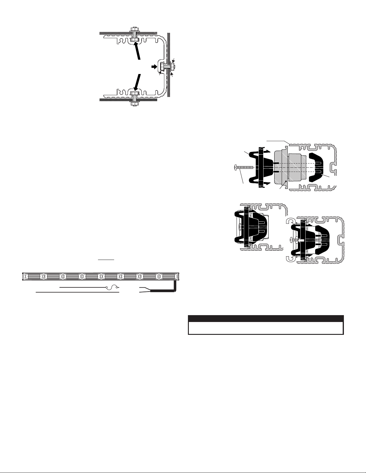
Installation:
CAUTION! DO NOT LOOK DIRECTLY AT THESE LEDS WHILE THEY ARE ON.
MOMENTAR Y BLINDNESS AND/OR EYE DAMAGE COULD RESULT!
IMPORTANT WARNING!
#10-24 ELASTIC
STOP NUT
#10 FLAT
WASHER
Extrusion end view (without end cap)
MOUNTING SURFACE
MOUNTING SURFACE
#10-24 X 3/4"
HEX HEAD
Mount to any 1
of 3 channels
in the extrusion
BRACKET
4 X 1-3/8
PHILLIPS PAN
HEAD PLASTILOC SCREW
Loosen screw, squeeze
bracket and pull out.
Side view of with Lighthead and BracketExtrusion
LIGHTHEAD
squeeze together
pull out
CLAMP
NUT
Note: When routing wires, it is
very important that you choose
a path that will keep the wires
away from any excessive heat or
any vehicle equipment that
could compromise the integrity
of the wires (ex. trunk lids, door
jams, etc.).
Note: Permanent mounting of
this product will require drilling.
It is absolutely necessary to
make sure that no other vehicle
components could be damaged
by this process. Check both sides of the mounting surface before
starting. If damage is likely, select a different mounting location.
1. Position the unit onto its mounting location. Draw a pencil line onto
the mounting surface along the top and bottom of the extrusion and a
“centerline” centered between the two.
2. Four 13/64” holes are required to mount this unit. These holes may
be located anywhere along the horizontal centerline that you drew in
step one. It’s best to locate the holes as far apart as possible. Mark
the hole locations onto the mounting surface.
3. Using a #9 drill bit, drill a hole in each of the hole locations marked.
4. Remove the endcap and slide the hex-head mounting bolts
(included) into any one of the three channels provided on the
extrusion (use the top, rear or bottom channel depending on which
position you wish to mount the unit) and reinstall the endcap.
5. Align these bolts with the 4 mounting holes and insert them into the
mounting holes.
6. Install a flat washer and elastic stop nut onto each bolt and tighten.
Wiring:
WARNING: All customer supplied wires that connect to the positive
terminal of the battery must be sized to supply at least 125% of the
maximum operating current and FUSED
load. DO NOT USE CIRCUIT BREAKERS WITH THIS PRODUCT!
Wire Connections:
1. Extend the RED wire to the battery and install a 10 amp fuse
block (customer supplied) on the end of the wire. Remove the
fuse before connecting any wires to the battery. Connect the
RED wire to the POSITIVE (+) battery terminal.
at the battery to carry that
IMPORTANT: There must not be more than 2 feet of wire between
fuse block and battery. The wire between fuse and battery is
unprotected, do not allow this wire to come in contact with any
other wires.
2. Extend the BLACK wire to the battery and connect it to the
battery ground. If your vehicle has a cable extending from the
negative terminal of the battery to the chassis, it is best to attach
the black wire at the chassis connection.
Operation:
This T/A is controlled by the Whelen wireless Traffic Advisor™
controller. Refer to the instructions that come with the controller
for operation.
Service:
This section shows you how to access the lightbar for service or lighthead
replacement. To
replace a lighthead,
first loosen the set
screw(s) on the
bracket. Now
squeeze the clip
together so that it
disengages from
the extrusion and
pull the bracket
straight out. With
the bracket
removed the
lighthead lifts out
and can be
unplugged from the
harness and
removed from the
lightbar.
IMPORTANT! It is
the responsibility
of the installation
technician to
make sure that the installation and operation of this product will not
interfere with or compromise the operation or efficiency of any
vehicle equipment!
IMPORTANT! Before returning this vehicle to active service, visually
confirm the proper operation of this product, as well as all vehicle
components/equipment.
Page 2
Page 3

SIDE
DRIVER'S
PASS.
SIDE
5
PART NO. KEY:
01-0684727-_8
5 = RED/CLEAR
1 = AMBER/CLEAR
{
LED/LENS COLOR
PART NO. KEY:
01-0684912-_8
5 = RED/CLEAR
1 = AMBER/CLEAR
{
LED/LENS COLOR
1
2
3
6
15
14
4
16
17
18
19
6
20
21
1
22
13
12
11
8109
26
27
7
SCREW, 4 x 1-3/8 PPH PLASTI-LOK
39-1V17268-01
11-36A055-045
46-076A026-00
46-076A150-00
39-1V17268-00
39-0917517-02
46-0743526-00
01-026A002-01
CLAMP NUT DIVIDER,
11-243415-017
26-0215001-06
15-04521B-220
19-343555-000
1
AR
4
AR
1
1
2
1
7
AR
2
1
1
1
1
1
1
1
1
1
1
1
4
4
4
01-0684912-_8
01-066B983-10
07-264851-000
11-243415-037
38-0143142-00
14-062219-06D
10-0523376-_8
07-243514-000
01-026A286-00
01-066B983-50
07-264851-001
T A ASSY 500 CONICAL LED SNAP-IN I/C
/,
ELECT.ASSY T A 500 FLASH 8 L T
, / - IGH
BRACKET EXT. MT. 500 SNAP-IN-HALF,
LHEAD 500 CON3 LED STEADY AMBER
LHEAD 500 LED ST DY REDCON3 EA
END CAP EXTR. MOUNT w SLOT,/
END CAP EXT SNAP-IN,,
CABLE POWER 2 C 14
, , - ONDUCTOR, AWG
SEAL INTERFACE 2 POS
,-
HARNESS ASSY PASS. - T A 500 LIN LED,/
HARNESS ASSY DR. - T A 500 LIN LED,/
WASHER, #10 FLAT - 631" OD X .060"
SCREW 10-24 X 3/4 HEX HD MS SS,"
SCREW #6-32 X 3/8 PPHMS
,
CABLE ASSY INT. CONTROL RF,
BRACKET EXT. MT. 500 SNAP-IN,
EXTRUSION T A 500 LED SNAP-IN,/
GASKET END CAP,
LABEL
BRACKET MTG. - RF MODULE,/
RF RECEIVER MODULE - T/A 500
GROMMET, .312" ID x .50" OD
TY-WRAP, 6" BLACK
NUT 10-24 ELASTIC STOP SS,
HOUSING PLUG 2 POS,,-
SEAL WIRE 2 POS,,-
21-11101612-0
46-0743478-01
16-1002220-50
14-104436-120
13-104120-062
2
3
ITEM
PART NUMBER
DESCRIPTION
QTY
11
12
13
14
15
16
17
18
19
20
4
5
6
7
8
9
10
1
21
22
23
24
25
9
9
26
27
39-1V17268-00
SEAL,INTERFACE 2 POS UMNL
15-04521B-220
19-343555-000
8
8
SCREW, #4 x 1 3/8" PPH
CLAMP NUT DIVIDER,
1
AR
4
1
1
1
2
1
7
AR
AR
2
1
1
1
1
1
1
1
1
1
4
1
4
4
01-026A286-00
RF RECEIVER MODULE - T/A 500
SCREW #6-32 X 3/8 PPHMS,"
T A 500 LIN LED/ , EAR ®
BRACKET MTG. - RF MODULE,
LABEL
07-243514-000
10-0523343-*8
14-062219-06D
01-0684727-_8
HARNESS, T/A 500 LINEAR LED, PASSENGER
SCREW 10-24 X 3/4 HEX HD MS SS, " not shown
WASHER, #10 FLAT - 631" OD X .060" not shown
HARNESS, T/A 500 LINEAR LED, DRIVER
CABLE, POWER, 2-CONDUCTOR, 14AWG.
END CAP, EXT - SNAP-IN with .50 HOLES
END CAP EXTR. MOUNT w SLOT,/
LIGHTHEAD, 500 LINEAR LED, STEADY,RED
LIGHTHEAD, 500 LINEAR LED, STEADY,AMBER
BRACKET EXT. MT. 500 SNAP-IN,
39-1V17268-01
SEAL WIRE 2 POS, , - ITION
HOUSING, PLUG, 2-POSITION
CABLE INT. CONTROL RF,
ELECT.ASSY T A 500 FLASH 8 L T, / - IGH
GASKET ENDCAP,
EXTRUSION T A 500 LED SNAP-IN,/
BRACKET EXT. MT. 500 SNAP-IN,
11-36A055-045
07-264851-001
01-066C289253
38-0143142-00
11-243415-037
01-066C289213
07-264851-000
46-076A150-00
46-076A026-00
39-0917517-02
46-0743526-00
01-026A002-01
NUT 10-24 ELASTIC STOP SS, , not shown
TY-WRAP, 6" BLACK
GROMMET, .312" ID x .50" OD
13-104120-062
14-104436-120
46-0743478-01
11-243415-017
26-0215001-06
21-11101612-0
16-1002220-50
2
3
ITEM
PART NUMBER
DESCRIPTION
QTY
11
12
13
14
15
16
17
18
19
20
4
5
6
7
8
9
10
1
21
22
23
24
25
26
27
PASS.
SIDE
DRIVER'S
SIDE
1
2
3
4
5
6
11
12
14
6
13
15
16
17
18
19
20
21
22
1
8109
26
27
7
Page 3
 Loading...