

Page 1

®
ENGINEERING COMPANY INC.
51 Winthrop Road
Chester, Connecticut 06412-0684
Phone: (860) 526-9504
Responder® HD Lightbar
Model: R2HD**, R9HD**, R10HD**
Installation Guide:
Fax: (860) 526-4078
Internet: www.whelen.com
Sales e-mail: autosale@whelen.com
Canadian Sales e-mail: canadiansales@whelen.com
Customer Service e-mail: custserv@whelen.com
Safety First
This document provides all the necessary information to allow your Whelen product to be properly and safely installed.
Before beginning the installation and/or operation of your new product, the installation technician and operator must
read this manual completely. Important information is contained herein that could prevent serious injury or damage.
• Proper installation of this product requires the installer to have a good understanding of automotive electronics,
systems and procedures.
• Failure to use specified installation parts and/or hardware will void the product warranty!
• If mounting this product requires drilling holes, the installer MUST be sure that no vehicle components or other
vital parts could be damaged by the drilling process. Check both sides of the mounting surface before drilling
begins. Also de-burr any holes and remove any metal shards or remnants. Install grommets into all wire
passage holes.
• If this manual states that this product may be mounted with suction cups, magnets, tape or Velcro®, clean the
mounting surface with a 50/50 mix of isopropyl alcohol and water and dry thoroughly.
• Do not install this product or route any wires in the deployment area of your air bag. Equipment mounted or
located in the air bag deployment area will damage or reduce the effectiveness of the air bag, or become a
projectile that could cause serious personal injury or death. Refer to your vehicle owner’s manual for the air bag
deployment area. The User/Installer assumes full responsibility to determine proper mounting location, based
on providing ultimate safety to all passengers inside the vehicle.
• For this product to operate at optimum efficiency, a good electrical connection to chassis ground must be
made. The recommended procedure requires the product ground wire to be connected directly to the NEGATIVE
(-) battery post.
• If this product uses a remote device to activate or control this product, make sure that this control is located in
an area that allows both the vehicle and the control to be operated safely in any driving condition.
• Do not attempt to activate or control this device in a hazardous driving situation.
• This product contains either strobe light(s), halogen light(s), high-intensity LEDs or a combination of these
lights. Do not stare directly into these lights. Momentary blindness and/or eye damage could result.
• Use only soap and water to clean the outer lens. Use of other chemicals could result in premature lens cracking
(crazing) and discoloration. Lenses in this condition have significantly reduced effectiveness and should be
replaced immediately. Inspect and operate this product regularly to confirm its proper operation and mounting
condition. Do not use a pressure washer to clean this product.
• It is recommended that these instructions be stored in a safe place and referred to when performing
maintenance and/or reinstallation of this product.
• FAILURE TO FOLLOW THESE SAFETY PRECAUTIONS AND INSTRUCTIONS COULD RESULT IN DAMAGE TO
THE PRODUCT OR VEHICLE AND/OR SERIOUS INJURY TO YOU AND YOUR PASSENGERS!
Automotive: Lightbars
For warranty information regarding this product, visit www.whelen.com/warranty
©2001 Whelen Engineering Company Inc.
Form No.13617H (062911)
Page 1
Page 2
IMPORTANT! The lightbar should be located a minimum of
NOTE: The cigar cord adaptor
is equipped with an 8 Amp fuse.
Use a replacement fuse with an
identical value.
Switch Functions:
SW1 = ON/OFF
SW2 = Scan-Lock™ / Momentary
CAUTION! DO NO T LOOK DIRECTLY AT THESE LEDS WHILE THEY ARE ON.
MOMENTAR Y BLINDNESS AND/OR EYE DAMAGE COULD RESULT!
IMPORTANT WARNING!
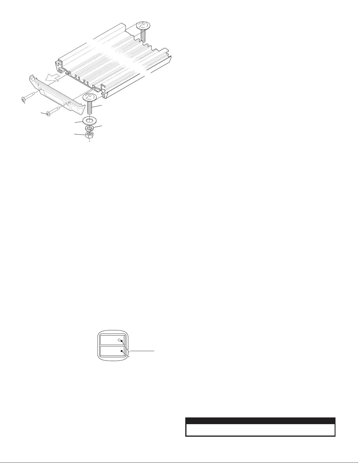
Remove
one end
cap
3/8-16
HEX NUT
3/8" SPLIT
LOCK WASHER
3/8" FLAT
WASHER
10-24 X 1.25"
TX PHD
SWADGE
3/8-16 X 1-1/4"
STEP BOLT
16" from any radio antennas!
Permanent Mounting:
First check to see that no vehicle components will interfere with the
selected mounting location. If you are installing the lightbar on the roof you
will need to remove the headliner from the vehicle. There may be a roof
support member that runs from the drivers to the passengers side of the
vehicle. Do not drill through this member. The mounting bolts can slide the
length of the bar, however you should keep them as close to the outer
edges of the bar as possible for stability. They must be on opposite
corners of the base.
1. When you have determined the mounting location, remove one of
the endcaps from the lightbar. Slide the two bolts in as shown then
hold the lightbar onto the vehicle and mark the location of the 2
mounting holes onto the mounting surface.
2. Drill the 2 mounting holes using a drill bit sized for a 5/16” hole.
3. Replace the end cap then insert the mounting bolts into the
mounting holes and secure them onto the lightbar with the mounting
hardware as shown.
4. Cut a 5/16” hole for the lightbar cable, install a rubber grommet
(customer supplied) to protect the cable then insert the cable onto
the wire hole and connect to power.
Temporary Mount (Optional)
WARNING: The use of any magnetically mounted warning device on
the outside of a vehicle in motion is not recommended and is at the
sole risk and responsibility of the user.
Magnetic/suction: Thoroughly
clean the proposed mounting
surface prior to mounting. For
suction cup mounting, wipe the
suction cup clean, place the
beacon onto its mounting surface
and apply gentle pressure to
ensure a good seal has been achieved. The Magnetic/Suction Cups
mount the same way as standard suction cups but are best suited to a flat,
steel surface. Magnetic: Place the beacon onto the mounting surface and
plug it into the vehicle cigar lighter.
Wiring:
WARNING! All customer supplied wires that connect to the positive
terminal of the battery must be sized to supply at least 125% of the
maximum operating current and FUSED at the battery to carry the
load. DO NOT USE CIRCUIT BREAKERS WITH THIS PRODUCT!
NOTE: See wiring diagrams on parts pages for wiring and fusing.
Operation:
R2HD** / Rotator Model: Applying +12 volts to the RED wire activates
the lightbar and rotators. No features are available for this lightbar.
R9HDM* / R9HDV* / R10HDM* / R10HDV* / Linear TIR™ & GEN
III Models: Plug cigar cord into vehicle lighter and turn the cigar plug
switch on to activate the lightbar. Pressing the Scan-Lock™ cigar cord
switch activates Scan-Lock™ flash pattern selection.
R9HDP* / R10HDP* / Linear TIR & GEN III Models: Applying + 12
volts to the RED wire activates the lightbar. Refer to the wiring diagrams
for functions for your model.
WHT/VIO - Scan-Lock™ / Flash Pattern Selection:
To operate Scan-Lock™ switch the lightbar on. Cigar plug models have
a momentary switch next to the on/off switch on the cigar plug.
Permanent mount models have a Scan-Lock™ function wire.
TO CHANGE PATTERNS: To cycle forward to the next available pattern
apply +12 volts to the WHT/VIO wire (Or press the momentary switch on
the cigar plug) for less than 1 second and release.
To cycle back to the previous pattern apply +12 volts to the WHT/VIO wire
(Or press the momentary switch) for more than 1 second and release.
TO CHANGE THE DEFAULT PATTERN: When the desired pattern is
displayed, allow it to run for more than 5 seconds. The lightbar will now
display this pattern when initially activated.
TO RESTORE THE FACTORY DEFAULT PATTERN: With power to the
lightbar off, apply +12 volts to the WHT/VIO wire (Or press and hold the
momentary switch). With power applied to Scan-Lock™, turn power to the
lightbar on. The factory default pattern will be displayed.
A normally open momentary switch can be used to control ScanLock™ operation.
NOTE: The features listed below apply to R10HDP* only.
GREY - Sync:
To SYNC two lightbars, configure both lightbars to display the same flash
pattern. With the power off, connect the GREY wire from each lightbar
together. When the lightbars are activated, their patterns will be
synchronized. Only the flash patterns designated for SYNC in the flash
pattern list may be used.
NOTE: Refer to parts pages for available flash pattern lists.
VIOLET - Hi/Low Power:
Allows user to step the unit down to low power for nighttime use.
Latching Mode: By applying +VBAT to the VIOLET wire for less than 1
second, the lightbar is “latched” into low power. The unit must be turned off
and then back on to restore normal operation (Momentary switch).
Level Mode: Applying +VBAT to the VIOLET wire for more than 1 second
keeps the lightbar in low power until voltage is removed (Toggle switch).
ORANGE - Pattern Override:
Applying +VBAT to the ORANGE wire while lightheads are activated, will
change the flash pattern to whatever pattern override is programmed for.
To program the flash pattern activate the lightbar then activate pattern
override by applying +VBAT to the ORANGE wire and select a flash
pattern using Scan-Lock™.
IMPORTANT! Before returning this vehicle to active service, visually
confirm the proper operation of this product, as well as all vehicle
components/equipment.
Caution: Permanent mounting of this product will require drilling. It
is absolutely necessary to make sure that no other vehicle
components could be damaged by this process. Check both sides of
the mounting surface before starting. If damage is likely, select a
different mounting location.
Page 2
Page 3

Fastex
grommets
(qty 4)
400 Linear TIR
(Shown for reference)
End mount
bracket
Standoff
1 - Remove endcap
screws and remove
endcaps.
2 - Remove dome
screws then remove
dome and gasket.
Washer
head
screw
Cable
clamp
Fastex
screw
grommet
6 X 1-1/4" PPH
Plastilk Black Phos.
Replacing LED Lightheads
Removing the Outer Dome
Snap-In
Bulb
Assembly
Lamp
Holder
SNAP-IN LAMP
H50SN12
P/N 34-0041987-01
Rotator & Mirror
Replacement:
The new rotator must be
mounted in the same location
as the old one to avoid
interference with any existing
parts. The illustration shows
where to locate the fastex
grommets in the base of the
lightbar. The mirrors are
mounted as shown. All
electrical connections are
the same as the old
rotator. If you
are
replacing an
old style rotator, you
must be sure to
remove all of the adhesive
tape that the old style rotator
used for mounting.
Halogen Bulb Replacement:
1. Remove
the lens.
2. Insert a
flat-blade
screw
driver into
the space
between
the lamp
holder and
the snap-in
assembly.
Gently
rotate the screw driver as shown. Repeat this
action until the bulb is loose.
3. Pull the bulb in an upward direction until it is
free.
4. Verify that the replacement bulb is the correct
wattage by the part numbers marked on the
bulb assembly. Insert the alignment tab of the
new bulb into the lamp holder and press
downwards to lock the bulb into place.
CAUTION: Replacing any halogen bulb requires
the use of safety glasses and gloves to prevent
injury. Do not handle the bulb with bare hands. Be
sure replacement bulb has same watt rating.
lightheads, first remove the dome and
endcaps as shown. To remove a lighthead from
its mounting bracket, unscrew the 4 washer
head screws, unplug the lighthead from its harness then
remove the lighthead from the lightbar. If you are removing
several lightheads make note of the which lightheads the
connectors go to for easier reassembly.
LED Replacement: 400
Series Linear TIR™ LEDS
are shown here for example.
Always disconnect the lightbar
from power before starting. To
replace or service your LED
Page 3
Page 4

16
18
17
10
6
34
7
30
11 12
13
14
15
19
23
24
25
26
27
28
4
3
1
29
9
31
32
BLACK wire to chassis ground
RED wire to +12 volts VDC
15 AMP FUSE
(
Customer Supplied
)
DOME COLORA=B=C=G=R=V=
AMBER
BLUE
CLEAR
GREEN
RED
VIOLET
MOUNTING CODE
M=
P=
MAGNET
PERMANENT
NUMBER OF ROTATORS2=3=
2 ROTATORS
3 ROTATORS
01-0683611-2 C M
EXAMPLE OF PART NUMBER
DOME COLOR
MOUNTING CODE
NUMBER OF ROTATORS
QTY
ITEM
DESCRIPTION
PART NUMBER
QTY
RESPONDER® HEAVY DUTY / MODEL R2HD
11-36D125-001
21-37001211-0
4
PLUG, DOME, .375" HOLE DIA DP 375, BLK NYLON
1
EXTRUSION, (FOR PERM. MOUNT)
01-0441771-02
68-1181893-V0
68-1181893-50
68-1181893-40
68-1181893-30
68-1181893-20
68-1181893-10
26-0215001-03
25-0910423-03
46-0920733-00
15-061416-080
38-0541780-00
68-5962342-01
15-081916-066
01-0441781-RO
01-0441781-VO
01-0441781-GO
01-0441781-BO
01-0441781-AO
02-0363276-02
21-27101404-0
66-0715403-00
11-362975-001
13-062C40-16J
21-1706090300
11-282151-000
14-0023347-00
10-0522845-__
01-0461640-07
01-0683611__P
01-0683611__M
1
1
1
88
2
4
4
2
4
4
1
A/R
1
1
A/R A/R
A/R
A/R
2
A/R2A/R
A/R
A/R
8
A/R
A/R
8
A/R A/R
1
2
4
1
2
4
2
2
5
2
2
5
A/R
A/R
A/R
A/R
A/R
A/R
A/R
A/R
1
A/R
A/R
KIT, 80LB MAG. STRAIGHT CORD #16 GA.
RESPONDER HEAVY DUTY (PERMANENT)
RESPONDER HEAVY DUTY (MAGNET)
LABEL, MODEL HD RESPONDER
SCREW, #8 X 3/8" PHEXWASHD SS TYPE B
SCREW GROMT, #6/#8 .265-.286 HOLE, .030 HD HT
KIT, VIOLET LENS
KIT, GREEN LENS
KIT, BLUE LENS
KIT,AMBER LENS
ROTATING REFLECTOR 150-12-50H
BUSHING, .437 MTG. HOLE .312 ID
THREADLOCKER, 242 LOCTITE 50ML
SCREW GROMMET #6 FASTEX
ENDCAP, COVER EXTRUSION
SCREW, 10-24 X 1.25" TX PHD
EXTRUSION
KIT, RED LENS
KIT, EXTRUSION STEP BOLT MOUNTING
TY WRAP, 3" BLACK
TERMINAL, BUTT
ASS'Y, 2 SOCKET/7" HARNESS
SCREW, 6 X 1/2 PPHSMS SS TYPE A
GASKET, .25 CORD EPDM SPONGE 44" LG
MIRROR 45° DIAMOND VPB SERIES
DOME-AMBER
DOME-VIOLET
DOME-RED
DOME-GREEN
DOME-CLEAR
DOME-BLUE
10-0323283-05
67-1011422120
67-1011400120
111
1
WIRE, 14 GA 12" BLK, STRIP BOTH ENDS
LABEL, MODEL RESPONDER not shown
WIRE, 14 GA 12" RED, STRIP BOTH ENDS
23
22
21
20
19
18
17
16
15
14
13
12
11
10
9
8
7
6
5
4
3
2
1
24
25
26
28
29
27
30
31
32
33
33
Page 4
Page 5

27
10
9
8
12
11
7
6
5
4
18
24
19
23
20
21 22
25
28
26
30
42
29
1413
15 16
17
26
31
35
25
34
21
33
37
36
OUTER
DOME COLORA=B=C=G=
R=
AMBER
BLUE
CLEAR
GREEN
RED
MOUNTINGM=P=
V=
MAGNET
PERMANENT
MAG-SUCTION
LED COLOR1=2=3=4=
5=
AMBER
BLUE
WHITE
GREEN
RED
01-0684688-2CM
EXAMPLE OF PART NUMBER
LEDCOLOR
MOUNTING
OUTER DOME COLOR
RESPONDER® HEAVY DUTY / MODEL R9HD**
ITEM
PART NUMBER
DESCRIPTION
QTY QTY QTY
CABLE CLAMP 1/4"D, 3/8"W .203" MTG HOLE
26-0115037-04
111
07-284937-000
222
BRACKET M G 400 LED RESPONDER SERIES/T
69-1343576-18
11-282151-000
38-0541780-00
10-0522845-__
14-0023347-00
15-061416-080
21-1706090300
21-27101404-0
01-0269936-00
26-0215001-03
46-0764924-00
66-0421074-00
25-0510223-05
10-0323283-05
66-0715403-00
A/R
111
4414
1
4
414
22
11
44
2
1
4
1111
1
1
111
A/R
11
33
A/R
A/R
111
CORD 2 SW CIGAR PLUG 10' 8 A FUSE #18/3/
GASKET .25 CORD EPDM SPONGE ECO BAR/.
END CAP COVER EXTRUSION ECONO LTBAR/.
BUSHING .437 MTG HOLE .312 ID BLK NYLON/
SCREW GROMMT #6 #8 .265-.286 HOLE, .030 HD HT/
TAPE M G STROBE BRACKET SERIES 4000/T
LABEL MODEL RESPONDER SERIES/
BUTT TERM 22-16 GA, INS/
SCREW 10-24 X 1.25" TX PHD SWADGE/
SCREW 6 X 1/2 PPHSMS SS TYPE A/
LABEL MODEL HEAVY DUTY RESPONDER/
ELECT 2 CH FLASHER
HARNESS 400 LINEAR LED GUARDIAN
TY WRAP 3" BLACK/
THREADLOCKER, 242 LOCTITE 50ML
KIT EXTRUSION STEP BOLT MT 3/8 X 1-1/4"/
PLATE ADAPTER MAG/SUCTION CUP MINI LTBAR/
400 LINEAR TIR LED BLUE 2 WIRE AMP
400 LINEAR TIR LED WHITE 2 WIRE AMP
400 LINEAR TIR LED AMBER 2 WIRE AMP
WASHER FLAT 1/4" 7/8 OD SS 17/64 ID .056-.070" THK/
PAD M MAG MT .406 DIATHRU HOLE/ TG / with
EXTRUSION, 16.00" INSERTS PERM/SUCTIONno /
SCREW 1/4-20 X 3/4 SKT HD SET NECK w/POINT SS
RESPONDER HEAVY DUTY MAGNET®/
EXTRUSION 16.00" INSERTS MAGNET/ with /
RESPONDER HEAVY DUTY SUCTION®/
RESPONDER HEAVY DUTY PERMANENT®/
SCREW 1/4-20 X 5/8 PPHMS
01-0684688__P
01-0684688__M
01-0441771-02
14-130216-100
11-362975-002
11-362975-001
01-0684688__V
DOME GREEN RESPONDER/
DOME RED RESPONDER/
DOME CLEAR RESPONDER/
DOME BLUE RESPONDER/
DOME AMBER RESPONDER/
WASHER 1/4 INTERNAL TOOTH LOCK
MAGNET X-80 NEW DMS NICKLE PLATED/
SCREW 1/4-20 X 3/4" HEX HD MS SS
SUCTION CUP / MAGNET MOUNT
16-1302820-06
08-0640834-01
16-1321560-02
65-0010192-00
14-130436-120
08-1583927-05
14-130536-12K
07-764726-023
68-1181893-40
68-1181893-10
68-1181893-20
68-1181893-30
01-026B569222
01-026B569232
01-026B569212
68-1181893-50
1
22242
A/R
A/R
A/R
A/R
A/R
A/R
A/R
A/R
A/R
A/R
24634
10
1
444
4
A/R
A/R
A/R
A/R
A/R
A/R
A/R
A/R
A/R
A/R
6
241034
400 LINEAR TIR LED GREEN 2 WIRE AMP
400 LINEAR TIR LED RED 2 WIRE AMP
SCREW 6 X 1 1/4" PPH PLASTILK BLACK PHOS/.
SCREW GROMMET #6/#8 FASTEX/
SCREW 8 X 3/8 PHEXWASHHD SS/
LENS CLEAR/OPTIC 43 HALOGEN/
01-026B569252
15-06541A-200
01-026B569242
13-062C40-16J
15-081916-066
68-1183304-30
A/R
A/R
A/R
A/R
A/R
A/R
A/R
A/R
1
1
A/R
A/R
6
241034
2
3
11
12
13
14
15
16
17
18
19
20
4
5
6
7
8
9
10
1
22
23
31
32
33
34
35
36
37
38
39
40
24
25
26
27
28
29
30
21
41
42
43
24
23
3
32
Scan-Lock™
WHITE/VIOLET
Chassis ground
+12 volts
+12 volts
15 Amp Fuse
Momentary switch
NOTE: All switches and fuses are customer supplied.
R HDP*9
BLACK
RED
1 Alternates with 2
1 & 2 Simultaneous
3 Cycles of 1A and 3 Cycles of 1S
1 Alternates with 2
1 & 2 Simultaneous
3 Cycles of 2A and 3 Cycles of 2S
1 Alternates with 2
1 & 2 Simultaneous
3 Cycles of 3A and 3 Cycles of 3S
1 Alternates with 2
1 & 2 Simultaneous
3 Cycles of 4A and 3 Cycles of 4S
1 & 2 Steady,3&4SingleFlash (SIM.)
1-2-3&4 Steady
1A1S1C2A2S2C3A3S3C4A4S4C5
6
#
FLASH PATTERN
OUTLET FUNCTION
SignalAlert™
SignalAlert™
SignalAlert™
CometFlash®
CometFlash®
CometFlash®
DoubleFlash
DoubleFlash
DoubleFlash
SingleFlash
SingleFlash
SingleFlash
SteadyFlash
Steady
Available Flash Patterns
18 19
20
22
21
Page 5
Page 6

18
33
37
19
32
36
3
20
31
21
35
47
1
22
2
18 19
20
25
21 22
24
27
26
28
25
7
6
5
4
24
34
26
25
9
11
8
10
12
RED - Power
BLK - Ground
7.5A Fuse
WHT/VIO - Scan-Lock™
Momentary
Switch
Connects to GREY wire of other
SYNC capable product (See Copy)
SP/ST Switch
VIO - Hi/Low Power
GREY - SYNC
CONTROL CABLE
ORG - Pattern Override
SP/ST Switch
SP/ST Switch
1A Fuse
BATTERY
ALL SWITCHES AND FUSES
ARE CUSTOMER SUPPLIED
WIRING DIAGRAM
13
30
14 15 16
29
17
43
Available Flash Patterns:
1.ActionScan™
2.SignalAlert™ (Alt)
3.SignalAlert (Sim)
4.SignalAlert (Alt/Sim)
5.CometFlash® (Alt)
6.CometFlash (Sim)
7.CometFlash (Alt-Sim)
8.DoubleFlash 75 (Alt)
9.DoubleFlash 75 (Sim)
10.DoubleFlash 75 (Alt-Sim)
11.SingleFlash 75 (Alt)
12.SingleFlash 75 (Sim)
13.SingleFlash 75 (Alt-Sim)
14.LongBurst™ (Alt)
15.LongBurst (Sim)
16.LongBurst (Alt-Sim)
17.SingleFlash 60 (Alt) CA
18.SingleFlash. 60 (Sim) CA
19.SingleFl. 60 (Alt-Sim) CA
20.SingleFlash 90 (Alt) CA
21.SingleFlash 90 (Sim) CA
22.SingleFl. 90 (Alt-Sim) CA
23.SingleFlash 120 (Alt) CA
24.SingleFlash 120 (Sim) CA
25.SingleFl. 120(Alt-Sim) CA
26.SingleFlash 300 (Alt)
27.SingleFlash 300 (Sim)
28.SingleFlash 300 (Alt-Sim)
29.MicroBurst™ (Alt)
30.MicroBurst (Sim)
31.MicroBurst (Alt-Sim)
32.ActionFlash™ (Alt)
33.ActionFlash (Sim)
34.ActionFlash (Alt-Sim)
35.PingPong™ (Alt)
36.PingPong (Sim)
37.FlimFlam (Alt.)
38.ModuFlash™ (Alt)
39.ModuFlash (Sim)
40.Steady 5%
41. Steady 1%
42.Steady 4%
43.Steady 8%
44.Steady 12%
45.Steady 40%
46.InOut
47.Sweep
48.LongBurst Sweep
49.InOut Blast
50.Sequence On/Off
51.ZigZag
52.Rotator 90
53.Rotator 120
54.Rotator 150
55.Rotator 250
CA =
Alt =
Sim =
Alt-Sim =
=
Calif. Title XIII Compliant
Alternating
Simultaneous
Alternating-Simultaneous
SYNC*
11-36D125-001
11-36D125-002
RESPONDER® HEAVY DUTY / MODEL R10HD_ _
2
3
11
12
13
14
15
16
17
18
19
20
4
5
6
7
8
9
10
1
22
23
31
32
33
34
35
36
37
38
39
40
24
25
26
27
28
29
30
21
41
42
43
44
45
OUTER
DOME COLOR
A=B=C=G=R=
AMBER
BLUE
CLEAR
GREEN
RED
MOUNTINGM=P=
V =
MAGNET
PERMANENT
MAG-SUCTION
LED COLOR
1 =
2 =
3 =
4 =
5 =
AMBER
BLUE
WHITE
GREEN
RED
01-0684691-2 C M
EXAMPLE OF PART NUMBER
LEDCOLOR
MOUNTING
OUTER DOME COLOR
111
CABLE CLAMP 1/4"D 3/8"W .203" MTG HOLE
01-0441771-02
A/R A/R A/R
A/R
4
1
1
1
1
444
4
2
2
2
A/R
2
A/R
24
A/R
A/R
A/R
A/R
30
A/R
A/R
A/R
A/R
A/R A/R
A/R A/R
A/R
A/R
A/R
A/R
A/R
A/R
A/R
A/R
A/R
A/R
24
A/R
666
A/R
24
66
30
22
30
6
2
SCREW 1/4-20 X 3/4 SKT HD SET NECKED with POINT SS
WASHER FLAT 1/4" 7/8 OD SS 17/64 ID .056-.070" THK/
PLATE ADAPTER MAG SUCTION CUP MINI LTBAR/-
EXTRUSION 16.00" W/O INSERTS PERMANENT SUCTION//-
PAD MOUNTING, MAG MT .406 DIA THRU HOLE/ with
BRACKET MTG 400 LED RESPONDER SERIES/
400 LED SPLIT BLU/BLU 2 POS AMP
SCREW 6 X 1" PPH PLASTILK BLACK PHOSPHATE/
400 LED SPLIT WHT/WHT 2 POS AMP
400 LED SPLIT RED/RED 2 POS AMP
400 LED SPLIT AMB/AMB 2 POS AMP
400 LED SPLIT GRN/GRN 2 POS AMP
SCREW 1/4-20 X 3/4" HEX HD MS SS
SUCTION CUP MAGNET MOUNT/
EXTRUSION 16.00" W/INSERTS MAGNET//
MAGNET X-80 NEW DMS NICKLE PLATED/
SCREW 1/4-20 X 5/8 PPHMS SS
KIT EXTRUSION STEP BOLT MT 3/8 X 1-1/4"/
WASHER 1/4 INTERNAL TOOTH LOCK
DOME AMBER RESPONDER/
DOME BLUE RESPONDER/
"Y" 4" HARNESS
SCREW 8 X 3/8 PHEXWASHHD SS/
SCREW GROMMET #6/#8 FASTEX
DOME RED RESPONDER/
DOME GREEN RESPONDER/
DOME CLEAR RESPONDER/
A/R
111
44
4
11
4
4
4
1
22
11
44
2
1
4
1111
1
1
111
A/R
11
11
A/R
11
A/R
1
1
1
1
1
1
CIGAR CORD PLUG ASSY, #18/3A DUAL SWITCH with TERMINALS
TAPE MOUNTING STROBE BRACKET SERIES 4000/
SCREW GROMMET, #6/#8 .265-.286 HOLE, .030 HD HT
BUSHING, .437 MTG HOLE .312 ID BLACK NYLON
END CAP COVER EXTRUSION ECONOMY LTBAR/
GASKET .25 CORD EPDM SPONGE ECONOMY BAR/
HOUSING 3 POSITION SOCKET HOUSING/
LABEL AIRBAG & MAG MT WARNING/
TY WRAP 3" BLACK/
HARNESS OUTPUT 6 CHANNEL/
ELECT 6 CHANNEL FLASHER
LABEL MODEL HEAVY DUTY RESPONDER/
SCREW 6 X 1/2 PPHSMS SS TYPE A/
SCREW 10-24 X 1.25" TX PHD SWADGE/
HARNESS / INPUT RESPONDER LP
HARNESS INPUT POWER CORD/
THREADLOCKER, 242 LOCTITE 50ML
LABEL MODEL RESPONDER SERIES/
RESPONDER HEAVY DUTY PERMANENT
®/
RESPONDER HEAVY DUTY SUCTION
®/
RESPONDER HEAVY DUTY MAGNET
®/
01-0684691__V
01-0684691__M
01-0684691__P
ITEM
PART NUMBER
DESCRIPTION
QTY QTY QTY
46
PLUG, DOME, .375" HOLE DIA DP 375, BLK NYLON
4
4
68-1181893-40
68-1181893-10
68-1181893-20
68-1181893-30
01-0286361255
15-06541A-160
01-0286361222
01-0286361233
01-0286361211
01-0286361244
68-1181893-50
13-062C40-16J
15-081916-066
11-282151-000
38-0541780-00
10-0522845-**
07-284873-000
14-0023347-00
15-061416-080
21-1706090300
21-27101404-0
01-026A213-00
26-0215001-03
46-076A239-00
66-0421074-00
08-0640834-01
14-130216-100
16-1321560-02
65-0010192-00
26-0115037-04
39-0403023-04
10-0322783-02
14-130436-120
07-764726-023
16-1302820-06
08-1583927-05
14-130536-12K
46-0921262-00
10-0323283-05
66-0715403-00
46-0743503-00
46-076A219-00
02-0243725-00
21-37001211-0
47
Page 6
 Loading...