

Page 1

®
ENGINEERING COMPANY INC.
51 Winthrop Road
Chester, Connecticut 06412-0684
Responder® LP Lightbar
Installation Guide:
Phone: (860) 526-9504
Fax: (860) 526-4078
Internet: www.whelen.com
Sales e-mail: autosale@whelen.com
Canadian Sales e-mail: canadiansales@whelen.com
Customer Service e-mail: custserv@whelen.com
Safety First
This document provides all the necessary information to allow your Whelen product to be properly and safely installed.
Before beginning the installation and/or operation of your new product, the installation technician and operator must
read this manual completely. Important information is contained herein that could prevent serious injury or damage.
• Proper installation of this product requires the installer to have a good understanding of automotive electronics,
systems and procedures.
• If mounting this product requires drilling holes, the installer MUST be sure that no vehicle components or other
vital parts could be damaged by the drilling process. Check both sides of the mounting surface before drilling
begins. Also de-burr any holes and remove any metal shards or remnants. Install grommets into all wire
passage holes.
• If this manual states that this product may be mounted with suction cups, magnets, tape or Velcro®, clean the
mounting surface with a 50/50 mix of isopropyl alcohol and water and dry thoroughly.
• Do not install this product or route any wires in the deployment area of your air bag. Equipment mounted or
located in the air bag deployment area will damage or reduce the effectiveness of the air bag, or become a
projectile that could cause serious personal injury or death. Refer to your vehicle owner’s manual for the air bag
deployment area. The User/Installer assumes full responsibility to determine proper mounting location, based
on providing ultimate safety to all passengers inside the vehicle.
• For this product to operate at optimum efficiency, a good electrical connection to chassis ground must be
made. The recommended procedure requires the product ground wire to be connected directly to the NEGATIVE
(-) battery post.
• If this product uses a remote device to activate or control this product, make sure that this control is located in
an area that allows both the vehicle and the control to be operated safely in any driving condition.
• Do not attempt to activate or control this device in a hazardous driving situation.
• This product contains either strobe light(s), halogen light(s), high-intensity LEDs or a combination of these
lights. Do not stare directly into these lights. Momentary blindness and/or eye damage could result.
• Use only soap and water to clean the outer lens. Use of other chemicals could result in premature lens cracking
(crazing) and discoloration. Lenses in this condition have significantly reduced effectiveness and should be
replaced immediately. Inspect and operate this product regularly to confirm its proper operation and mounting
condition. Do not use a pressure washer to clean this product.
• It is recommended that these instructions be stored in a safe place and referred to when performing
maintenance and/or reinstallation of this product.
• FAILURE TO FOLLOW THESE SAFETY PRECAUTIONS AND INSTRUCTIONS COULD RESULT IN DAMAGE TO
THE PRODUCT OR VEHICLE AND/OR SERIOUS INJURY TO YOU AND YOUR PASSENGERS!
Automotive: Lightbars
For warranty information regarding this product, visit www.whelen.com/warranty
©2007 Whelen Engineering Company Inc.
Form No.14106K (060711)
Page 1
Page 2
IMPORTANT! The lightbar
should be a minimum of 16"
from any radio antennas!
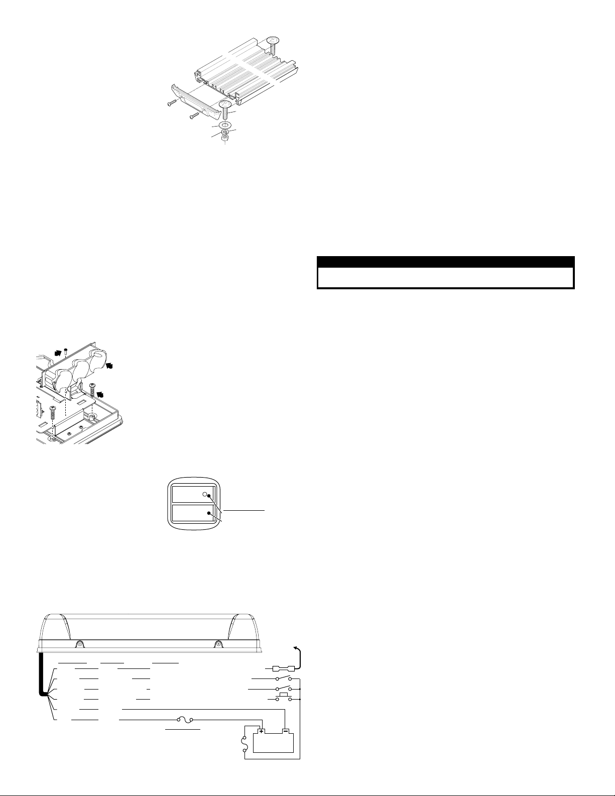
Permanent Mounting:
This mounting style requires removal of
the headliner. There may be a roof
support member that runs from the
drivers to the passengers side of the
vehicle. Do not drill through this
member.
Caution: Permanent mounting of this
product will require drilling. It is absolutely necessary to make sure that no
other vehicle components could be damaged by this process. Check both
sides of the mounting surface before starting. If damage is likely, select a
different mounting locati on.
1. When the mounting location has been determined, slide the 2 mounting bolts
into the lightbar extrusion, one bolt in each track. Position these bolts so that
they are at opposite ends of the extrusion and as far appart as possible.
2. Place the lightbar on the vehicle in its proposed mounting location. Mark the
location of the 2 mounting bolts onto the mounting surface. Also, mark the area
for the wire passage hole. This hole should be located directly below where the
wires exit the extrusion.
3. Remove the lightbar and drill two, 5/16” dia. mounting holes and a 5/16” dia.
wire passage hole. De-burr all three holes and install a rubber grommet
(customer supplied) into the wire passage hole.
4. Route the wires through the grommet and to the necessary switches and
power source as shown in the diagram below.
5. Secure the Responder® to the vehicle using the hardware provided. From the
underside of the mounting surface, apply RTV around each mounting hole and
the grommeted wire passage hole to prevent water from entering these
openings.
Remove
screw
Lift lighthead
out to access
mounting
screws.
Permanent Mounting / Plastic Base
1.
1.
1.
2.
.
2
3.
.
3
.
3
.
3
4.
.
4
5
.
Remove
one end
cap
3/8-16 X 1-1/4"
STEP BOLT
3/8" FLAT
WASHER
3/8-16
HEX NUT
Remove the outer dome and the screws that hold
down the endcap lightheads
and lift the (2)
Install the #10 screws into the 4 mounting holes
to open up the holes.
Remove the screws, position the base on the
proposed mounting location then scribe the
mounting surface where the mounting holes are
to be drilled.
Remove the base and drill the 4 mounting holes
using a # drill .
Install the lightbar. Replace the lightheads & dome.
lightheads out.
16 bit
3/8" SPLIT
LOCK WASHER
(use a T-10 TORX bit)
Temporary Mount (Magnetic, Suction Cup, etc.):
WARNING: The use of any
magnetically mounted warning
device on the outside of a vehicle in
motion is not recommended and is at
the sole risk and responsibility of the
user.
Magnetic/suction: Thoroughly clean
the proposed mounting surface prior to
mounting. For suction cup mounting, wipe the suction cup clean, place the beacon
onto its mounting surface and apply gentle pressure to ensure a good seal has been
achieved. The Magnetic/Suction Cups mount the same way as standard suction
cups but are best suited to a flat, steel surface. Magnetic: Place lightbar onto the
mounting surface and plug it into the vehicle cigar lighter.
Wiring Diagram:
All models except R2LPQH (See page 3)
Responder® LP
Wire Color
GREY SYNC Networks with other SYNC-capable lights
VIOLET
ORANGE
WHT/VIO
BLACK
RED
NOTE:
All fuses and switches
are customer supplied
Function Operation
Low Power
Pattern Override
Scan-Lock™
Apply +VBATT for Low Power mode
Apply +VBATT for Pattern Override
Flash Pattern Selection (see pattern list)
Ground
Power
Fuse Values
24 Volt Models
R1LP***
R2LPH***
-5A
-5A
- 7.5A
NOTE: The cigar cord adaptor
is equipped with an 8 Amp fuse.
Use a replacement fuse with an
identical value.
Switch Functions:
SW1 = ON/OFF
SW2 = Scan-Lock™ / Momentary
(
12 volt model only
1A
Fuse
)
Connect to
GREY SYNC
wire from
another
SYNC light
BUTT SPLICE
12 24V/ V
Battery
Wiring:
WARNING! All customer supplied wires that connect to the positive terminal of
the battery must be sized to supply at least 125% of the maximum operating
current and FUSED at the battery to carry the load. DO NOT USE CIRCUIT
BREAKERS WITH THIS PRODUCT!
Scan-Lock™:
To operate Scan-Lock, switch the lightbar on. The Scan-Lock wire will be either
WHT/VIO or WHT (See wiring) Magnetic and Suction mount models use a
momentary switch on the cigar plug instead of a wire (12 volt only).
TO CHANGE PATTERNS: To cycle forward to the next pattern apply +VBAT to the
Scan-Lock wire (or switch) for less than 1 second and release. To cycle back to the
previous pattern apply +VBAT to Scan-Lock™ wire for over 1 second and release.
TO CHANGE THE DEFAULT PATTERN: When the desired pattern is displayed,
allow it to run for more than 5 seconds. The lighthead will now display this pattern
when initially activated.
TO RESTORE THE FACTORY DEFAULT PATTERN: With power off, apply +VBAT
to the Scan-Lock™ wire (or switch). While continuing to apply power to Scan-Lock
turn lighthead(s) on. The factory default pattern will be displayed.
A Normally Open momentary switch can be used to control Scan-Lock. See
below for available flash patterns.
IMPORTANT WARNING!
CAUTION! DO NOT LOOK DIRECTLY AT THESE LEDS WHILE THEY ARE ON.
MOMENTARY BLINDNESS AND/OR EYE DAMAGE COULD RESULT!
Available Flash Patterns:
1. ActionScan™
2. SignalAlert™ ALT
3. SignalAlert Sim)
4. SignalAlert (Alt/Sim)
5. CometFlash® (Alt)
6. CometFlash (Sim)
7. CometFlash (Alt-Sim)
8. DoubleFlash 75 (Alt)
9. DoubleFlash 75 (Sim)
10.DoubleFlash 75 (Alt-Sim)
11.SingleFlash 75 (Alt)
12.SingleFlash 75 (Sim)
13.SingleFlash 75 (Alt-Sim)
14.LongBurst™ (Alt)
15.LongBurst (Sim)
16.LongBurst (Alt-Sim)
17.SingleFlash 60 (Alt) CA
18.SingleFlash. 60 (Sim) CA
CA = Calif. Title XIII Com pliant Alt = Alternating Sim = Simultaneo us Alt-Sim = Alternating-Simultaneous
= SYNC
*
19.SingleFl. 60 (Alt-Sim) CA
20.SingleFlash 90 (Alt) CA
21.SingleFlash 90 (Sim) CA
22.SingleFl. 90 (Alt-Sim) CA
23.SingleFlash 120 (Alt) CA
*
24.SingleFlash 120 (Sim) CA
*
25.SingleFl. 120(Alt-Sim) CA
26.SingleFlash 240 (Alt)
*
27.SingleFlash 240 (Sim)
*
28.SingleFlash 240 (Alt-Sim)
29.MicroBurst™ (Alt)
*
30.MicroBurst (Sim)
*
31.MicroBurst (Alt-Sim)
32.ActionFlash™ (Alt)
*
33.ActionFlash (Sim)
*
34.ActionFlash (Alt-Sim)
35.PingPong™
36.FlimFlam (Alt.)
37.ModuFlash™ (Alt)
38.ModuFlash (Sim)
39.Steady 2.5%
40. Steady 4%
41.Steady 6%
42.Steady 8%
43.Steady 12%
44.Steady 40%
45.InOut
46.Sweep
47.LongBurst Sweep
48.InOut Blast
49.Sequence On/Off
50.ZigZag
51.Rotator 90
52.Rotator 120
53.Rotator 150
54.Rotator 250
Sync:
To SYNC two lightbars, configure both lightbars to display the same flash pattern.
With the power off, connect the GREY wire from each lightbar together. When the
lightbars are activated, their patterns will be synchronized. Only the flash patterns
designated for SYNC in the flash pattern list may be used.
Hi/Low Power:
Allows user to step the unit down to low power for nighttime use.
Latching Mode: By applying +VBAT to the VIOLET wire for less than 1 second, the
lightbar is “latched” into low power. The unit must be turned off and then back on to
restore normal high power operation (Momentary switch).
Level Mode: Applying +VBAT to the VIOLET wire for more than 1 second holds the
lightbar in low power mode until voltage is removed (Toggle switch).
Pattern Override:
Applying +VBAT to the ORANGE wire while lightheads are activated, will change the
flash pattern to whatever pattern override is programmed for. To program the flash
pattern activate the lightbar then activate pattern override by applying +VBAT to the
ORANGE wire and select a flash pattern using Scan-Lock.
IMPORTANT! It is the responsibility of the installation technician to make sure
that the installation and operation of this product will not interfere with or
compromise the operation or efficiency of any vehicle equipment! Before
returning the vehicle to active service, visually confirm the proper operation of
this product, as well as all vehicle components/equipment.
Page 2
Page 3
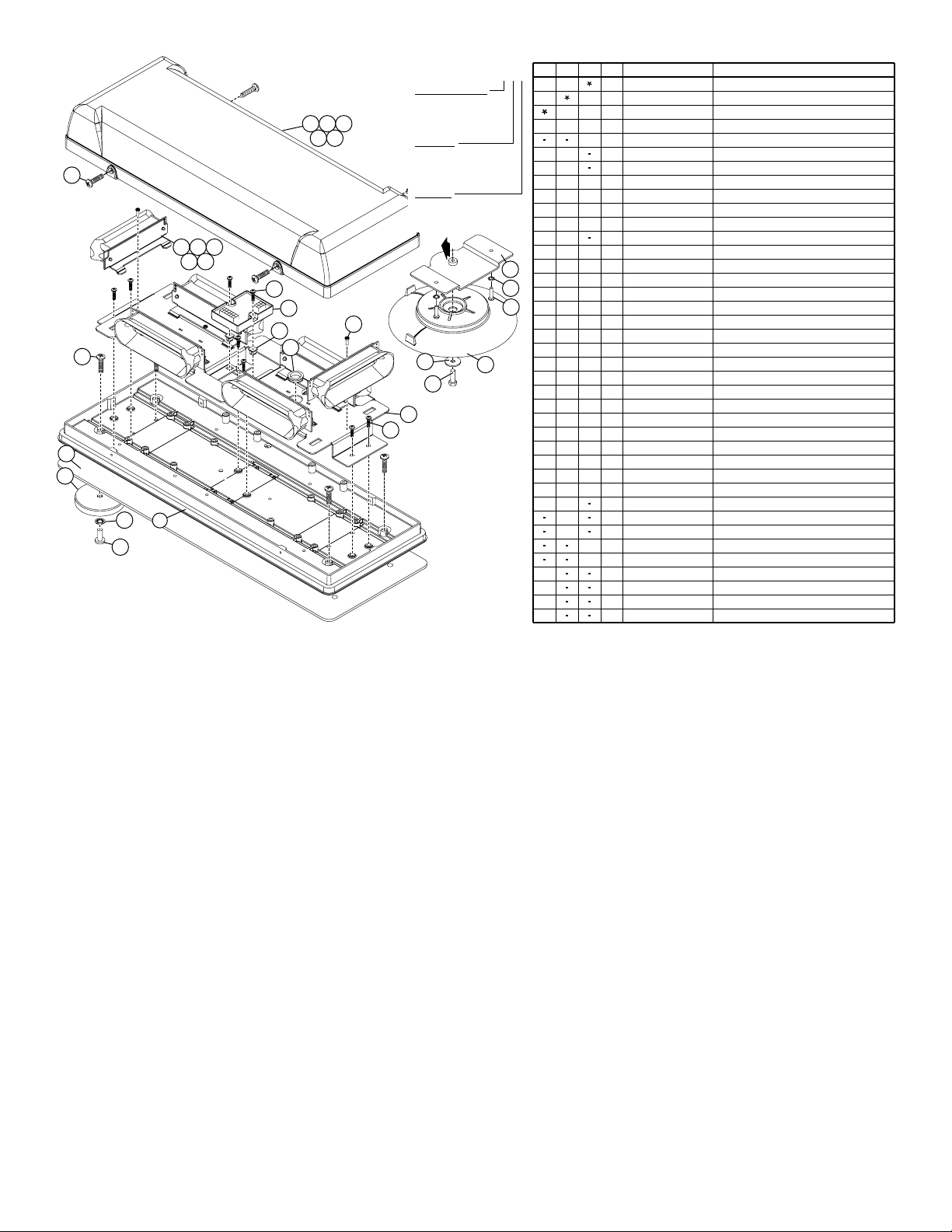
ITEM PART NUMBER DESCRIPTION
1
1
22
717
212
11
11
A/R
A/R
A/R
A/R
A/R
A/R
A/R
A/R
66
121
1
A/R
A/R
A/R
A/R
A/R
A/R
A/R
A/R
A/R
A/R
44
4
4
4
1
2
1
3
4
5
6
1
7
8
9
10
11
12
13
14
15
16
17
18
19
2
20
1
21
22
23
24
25
26
27
28
29
30
31
4
32
1
33
34
35
36
01-0684791__P
01-0684791__M
01-0684791__V
11-381890-000
46-076A219-00
02-0243725-00
46-0743503-00
13-062C40-16J
26-0115037-04
15-081416-060
26-0215001-06
39-0403023-04
11-386602-000
21-11263204-0
01-026A518-11
01-026A518-21
01-026A518-31
01-026A518-41
01-026A518-51
14-040285-063
01-026A213-00
15-081416-080
46-076A239-00
26-0215001-03
68-2986619-10
68-2986619-20
68-2986619-30
68-2986619-40
68-2986619-50
15-061416-080
15-101416-100
16-1021220-45
65-0010191-00
15-101416-160
38-026A402-00
14-130436-120
16-1302820-06
08-1583927-05
07-76A350-023
RESPONDER LP, PERMANENT MT
RESPONDER LP, MAGNET MT
RESPONDER LP, SUCTION MT
BASE, HOUSING RESPONDER 2
HARNESS INPUT RESPONDER LP
CORD, CIGAR PLUG DUAL SWITCH
HARNESS INPUT POW CORD DUAL SW LP. RSPNDR
SCREW GROMMET, #6/#8 FASTEX FASTEX
CABLE CLAMP, 1/4"D, 3/8"W .203" MTG HOLE, BLK
SCREW, 8 X 3/8 PPHSMS 410 SS TYPE A
TY WRAP, 6" BLACK
HOUSING, 3 POS SOCKET COMM MATE-N-LOK
BASE, MTG LIGHTHEADS LPRSPNDR
GROMMET, 1" SLIM LINE
LIN6 LED 12V AMB JUSTICE CREE
LIN6 LED 12V BLU JUSTICE CREE
LIN6 LED 12V WHT JUSTICE CREE
LIN6 LED 12V GRN JUSTICE CREE
LIN6 LED 12V RED JUSTICE CREE
SCREW, 4-40 X 3/8 TORX PH TRLBLR 410 SS, BLK OX.
ASS'Y, PCB RESPONDER FLASHER 6 CHANNEL
SCREW, 8 X 1/2 PPHSMS 410 SS
ASS'Y, HARNESS 6 OUTPUT RESPONDER LP
TY WRAP, 3" BLACK
DOME, AMB NO OPTIC LP no MTG DETAILRSPNDR
DOME, BLU NO OPTIC LP MTG DETAILRSPNDR no
DOME, CLR NO OPTIC LP MTG DETAILRSPNDR no
DOME, GRN NO OPTIC LP MTG DETAILRSPNDR no
DOME, RED NO OPTIC LP MTG DETAILRSPNDR no
SCREW, 6 X 3/8 PPH PLASTI LOK
SCREW, 10 X 5/8 PPHSMS 410 SS
WASHER, #10 INT TOOTH LOCK SS
MAGNET, X-50 (RB-50) NICKLE PLATEDRSPNDR
SCREW, 10 X 1 PPHSMS TYPE A
GASKET, MOUNTING RESPONDER 2
SCREW, 1/4-20 X 3/4" HEX HD MS SS
WASHER, FLAT 1/4" 7/8 OD SS 17/64 ID .056-.070" THK
SUCTION CUP, MAGNET MOUNT
PLATE, ADAPTR MAG/SUC. MT BLACK RSPNDR LP
36
29
28
QTY QTY QTY
1 1 1
1
1
2
1
7
2
1
1
1
A/R A/RA/R
A/R
A/R
A/R
A/R
6
1
2
1
A/R
A/R A/RA/R
A/R
A/R
A/R
A/R
RESPONDER LP
LINEAR 6 LED
22
23
24
25
26
27
12
13
14
15
16
01-0684791___
OUTER DOME COLOR
A=
AMBER
B=
BLUE
C=
CLEAR
G=
GREEN
R=
RED
LED COLOR
1=
AMBER
2=
BLUE
3=
WHITE
4=
GREEN
5=
RED
MOUNTING
P=
PERMANENT
M=
MAGNET
V=
MAGNET/SUCTION
CUP MOUNTV=
TOWARD
CENTER
19
18
5
31
11
17
34
35
33
10
7
32
30
4
4
1
29
28
2
2
2
2
Page 3
Page 4

44
32 30
26
25
24
QTY QTY QTY
29
3133
46
27
34
46
18
16
14
15
17
21
13
20
19
12
9
21
7
28
1
1
1
1
9
1
7
2
1
1
1
A/R
A/R
A/R
A/R
6
2
1111
A/R
4
2
4
2
A/R
A/R
A/R
A/R A/RA/R
A/R
4
3
45
2
2
2
4
2
2
11
RESPONDER LP
HEAVY DUTY
3 CONICAL LED
01-0684742___
41
42
43
37
39
38
36
35
ITEM PART NUMBER DESCRIPTION
1
1
1
1
9
1
7
2
1
1
1
A/R
A/R
A/R
A/R
6
1
2
A/R
4
2
4
2
A/R
A/R
A/R
A/R
4
4
4
4
4
A/R
2 2
1
1
1
9
1
7
2
1
1
A/R
A/R
A/R
A/RA/RA/R
A/R
6
1
2
A/R
4
2
4
2.662.662.66
2
A/R
A/R
A/R
A/R
4
1
01-0684742__P
01-0684742__M
01-0684742__V
11-36D115-002
1
11-36D115-001
2
21-11101610-0
3
46-076A219-00
4
5
02-0243725-00
46-0743503-00
6
7
13-062C40-16J
26-0115037-04
8
15-081416-060
9
26-0215001-06
10
39-0403023-04
11
11-386602-000
12
21-11263204-0
13
01-026B568-10
14
01-026B568-20
15
01-026B568-30
16
01-026B568-40
17
01-026B568-50
18
14-040285-063
19
01-026A213-00
20
15-081416-080
21
46-076A239-00
22
26-0215001-03
23
21-1706090300
24
25
11-282151-000
14-0023347-00
26
27
38-0541780-00
28
38-0143763-00
29
68-2986618-10
68-2986618-20
30
68-2986618-30
31
68-2986618-40
32
68-2986618-50
33
15-061416-080
34
01-0441771-02
35
14-130216-100
36
16-1321560-02
37
65-0010192-00
38
08-0640834-01
39
66-0715403-00
40
14-130436-120
41
16-1302820-06
42
08-1583927-05
43
14-130536-12K
44
45
07-764726-023
10-0523326-00
46
10-0322783-02
47
RESPONDER LP, HEAVY DUTY, PERM. MT
RESPONDER LP, HEAVY DUTY, MAG MT
RESPONDER LP, HEAVY DUTY, SUC MT
BASE 15.88" MACH. no RIVNUTS LP RSPNDR
BASE 15.88" MACH. RIVNUTS LP RSPNDR
GROMMET, 5/16 ID X 1/2 HOLE
ASS'Y, HARNESS INPUT RESPONDER LP
CORD, CIGAR PLUG DUAL SWITCH
HARNESS INPUT PWR CRD DUAL SW LPRSPND
SCREW GROMMET, #6/#8 FASTEX FASTEX
CAB. CLAMP, 1/4"D, 3/8"W .203" MT. HOLE, BLK
SCREW, 8 X 3/8 PPHSMS 410 SS TYPE A
TY WRAP, 6" BLACK
HOUSING, 3 POS SOCKET COMM MATE-N-LOK
BASE, MTG LIGHTHEADS RESPONDER LP
GROMMET, 1" SLIM LINE
SUB ASSY, CON3 HINGE AMB AMP JUSTICE
SUB ASSY, CON3 HINGE BLU AMP JUSTICE
SUB ASSY, CON3 HINGE WHT AMP JUSTICE
SUB ASSY, CON3 HINGE GRN AMP JUSTICE
SUB ASSY, CON3 HINGE RED AMP JUSTICE
SCREW, 4-40 X 3/8 TORX PH TRLBLR 410 SS, BLK OX.
PCB RESPONDER FLASHER 6 CHANNEL
SCREW, 8 X 1/2 PPHSMS 410 SS
ASS'Y, HARNESS 6 OUTPUT LPRSPNDR
TY WRAP, 3" BLACK
GROMMET, #6/#8 .265-.286 HOLE, .030 HD HT
ENDCAP, CVR EXTRUSION ECONO LTBAR
SCREW, 10-24 X 1.25" TX PHD SWEDGE FM
GASK, .25 CORD EPDM SPONGE ECONO BAR
GASKET, DOME ENDCAP RESPONDER LP
DOME, AMB OPTIC LP no MTG DETAILRSPNDR
DOME, BLU OPTIC LP no MTG DETAILRSPNDR
DOME, CLR OPTIC LP no MTG DETAILRSPNDR
DOME, GRN OPTIC LP no MTG DETAILRSPNDR
DOME, RED OPTIC LP no MTG DETAILRSPNDR
SCREW, 6 X 1/2 PPHSMS SS TYPE A
KIT, EXTR STEP BOLT MT 1-1/4" AUTOBWL FEED.
SCREW, 1/4-20 X 5/8 PPHMS
WASHER, 1/4 INTRNAL TOOTH LOCK
MAG., X-80 NEW DMS RB80) NICKLE PLATE
PAD, MTG, MAG MT W/.406 DIATHRU HOLE
THREADLOCKER, 242 LOCTITE
SCREW, 1/4-20 X 3/4" HEX HD MS SS
WSHR, FLT 1/4" 7/8 OD SS 17/64 ID .056-.070" THK
SUCTION CUP, MAGNET MOUNT
SCREW, 1/4-20 X 3/4 SKT HD SET NECK POINT SS
PLATE, ADAPT MAG/SUC CUP MINI LTBAR
LABEL, M/N RESPONDER LP SERIES
LABEL, AIRBAG & MAG MT WARNING
OUTER DOME COLOR
A=
AMBER
B=
BLUE
C=
CLEAR
G=
GREEN
R=
RED
LED COLOR
1=
AMBER
2=
BLUE
3=
WHITE
4=
GREEN
5=
RED
MOUNTING
P=
PERMANENT
M=
MAGNET
V=
MAGNET/SUCTION
CUP MOUNTV=
Page 4
Page 5

QTY QTY QTY
11
1
1
1
1
2
22
1
717
7
2 2
2
1
1
11
1
11
1
A/R A/R A/R
A/R
A/R
A/R
A/R
A/R
A/R
A/R
A/R
A/R
A/R
A/R
A/R
66
6
121
1
2
1
11
A/R
A/R
A/R
A/R A/R A/R
A/R
A/R
A/R
A/R
A/R
A/R
A/R
A/R
A/R
A/R
A/R
A/R
4
4
4
4
4
2
2
2
2
2
2
1
1
11
1
ITEM PART NUMBER DESCRIPTION
1
1
1
2
3
4
5
6
1
7
8
9
10
11
12
13
14
15
16
17
18
19
2
20
21
22
23
24
25
26
44
27
28
29
30
31
4
32
1
33
34
35
36
37
2
38
39
01-0684730__P
01-0684730__M
01-0684730__V
11-381890-000
46-076A219-00
02-0243725-00
46-0743503-00
13-062C40-16J
26-0115037-04
15-081416-060
26-0215001-06
39-0403023-04
11-386602-000
21-11263204-0
01-026B568-10
01-026B568-20
01-026B568-30
01-026B568-40
01-026B568-50
14-040285-063
01-026A213-00
15-081416-080
46-076A239-00
26-0215001-03
68-2986618-10
68-2986618-20
68-2986618-30
68-2986618-40
68-2986618-50
15-061416-080
15-101416-100
16-1021220-45
65-0010191-00
15-101416-160
38-026A402-00
14-130436-120
16-1302820-06
08-1583927-05
07-76A350-023
10-0523326-00
10-0322783-02
10-0523370-__
RESPONDER LP, PERMANENT MT
RESPONDER LP, MAGNET MT
RESPONDER LP, SUCTION MT
BASE, HOUSING RESPONDER 2
HARNESS INPUT LPRSPNDR
CORD, CIGAR PLUG DUAL SWITCH
HARNESS INPUT POW. CORD DUAL SW RSPNDR LP
SCREW GROMMET, #6/#8 FASTEX
CABLE CLAMP, 1/4"D, 3/8"W .203" MTG HOLE, BLACK
SCREW, 8 X 3/8 PPHSMS 410 SS TYPE A
TY WRAP, 6" BLACK
HOUSING, 3 POS SOCKET COMM MATE-N-LOK
BASE, MTG LIGHTHEADS RESPONDER LP
GROMMET, 1" SLIM LINE
SUB ASSY, CON3 HINGE AMB AMP JUSTICE
SUB ASSY, CON3 HINGE BLUE AMP JUSTICE
SUB ASSY, CON3 HINGE WHITE AMP JUSTICE
SUB ASSY, CON3 HINGE GREEN AMP JUSTICE
SUB ASSY, CON3 HINGE RED AMP JUSTICE
SCREW, 4-40 X 3/8 TORX PH TRLBLR 410 SS, BLK OX.
PCB RESPONDER FLASHER 6 CHANNEL
SCREW, 8 X 1/2 PPHSMS 410 SS
HARNESS 6 OUTPUT RESPONDER LP
TY WRAP, 3" BLACK
DOME, AMB OPTIC LP W/O MTG DETAILSRSPNDR
DOME, BLU OPTIC LP W/O MTG DETAILSRSPNDR
DOME, CLR OPTIC LP W/O MTG DETAILSRSPNDR
DOME, GRN OPTIC LP W/O MTG DETAILSRSPNDR
DOME, RED OPTIC LP W/O MTG DETAILSRSPNDR
SCREW, 6 X 3/8 PPH PLASTI LOK
SCREW, 10 X 5/8 PPHSMS 410 SS
WASHER, #10 INT TOOTH LOCK STAINLESS STEEL
MAGNET, X-50 (RB-50) NICKLE PLATEDRSPNDR
SCREW, 10 X 1 PPHSMS TYPE A
GASKET, MOUNTING RESPONDER 2
SCREW, 1/4-20 X 3/4" HEX HD MS SS
WASHER, FLAT 1/4" 7/8 OD SS 17/64 ID .056-.070" THK
SUCTION CUP, MAGNET MOUNT
PLATE, ADAPTER MAG/SUC MT BLK LP. RSPNDR
LABEL, M/N RESPONDER LP SERIES
LABEL, AIRBAG & MAG MT WARNING
LABEL, MODEL / SERIAL NUMBER
36
29
28
35
34
33
RESPONDER LP
CONICAL 3 LED
01-0684730___
OUTER DOME COLOR
A=
AMBER
B=
BLUE
C=
CLEAR
G=
GREEN
R=
RED
LED COLOR
1=
AMBER
2=
BLUE
3=
WHITE
4=
GREEN
5=
RED
MOUNTING
P=
PERMANENT
M=
MAGNET
V=
MAGNET/SUCTION
CUP MOUNTV=
23 26
25
2422
37
27
37
17
13
12
161415
19
18
5
31
11
10
7
32
30
1
29
28
Page 5
Page 6

QTY QTY QTY
1
1
1
1
9
1
7
2
1
1
1
A/R
A/R
A/R
A/R
6
1
2
11 1
A/R
4
2
4
2
A/R
A/R
A/R
A/R A/RA/R
A/R
4
2
2
2
4
2
2
11
HEAVY DUTY LINEAR 6
ITEM PART NUMBER DESCRIPTION
1
1
2
1
3
1
1
4
1
5
1
6
1
7
9
9
8
1
1
9
7
7
10
2
2
11
1
1
12
1
13
1
1
A/R
A/R
A/R
A/R
A/R
14
15
A/R
16
A/R
A/RA/RA/R
17
18
A/R
19
6
6
20
1
1
21
2
2
22
23
A/R
A/R
4
4
24
25
2
2
26
4
4
2.662.662.66
27
28
2
2
A/R
A/R
A/R
29
30
31
A/R
A/R
A/R
32
A/R
A/R
34
4
4
35
1
36
4
37
4
38
4
39
4
40
33
A/R
41
42
43
44
45
46
2
2
47
RESPONDER LP
01-0684792___
01-0684792__P
01-0684792__M
01-0684792__V
11-36D115-002
11-36D115-001
21-11101610-0
46-076A219-00
02-0243725-00
46-0743503-00
13-062C40-16J
26-0115037-04
15-081416-060
26-0215001-06
39-0403023-04
11-386602-000
21-11263204-0
01-026A518-11
01-026A518-21
01-026A518-31
01-026A518-41
01-026A518-51
14-040285-063
01-026A213-00
15-081416-080
46-076A239-00
26-0215001-03
21-1706090300
11-282151-000
14-0023347-00
38-0541780-00
38-0143763-00
68-4986619-10
68-4986619-20
68-4986619-30
68-4986619-40
68-4986619-50
15-061416-080
01-0441771-02
14-130216-100
16-1321560-02
65-0010192-00
08-0640834-01
66-0715403-00
14-130436-120
16-1302820-06
08-1583927-05
14-130536-12K
07-764726-023
10-0523326-00
10-0322783-02
OUTER DOME COLOR
A=
B=
C=
G=
R=
RESPONDER LP, HEAVY DUTY, PERMANENT MT
RESPONDER LP, HEAVY DUTY, MAGNET MT
RESPONDER LP, HEAVY DUTY, SUCTION MT
BASE, 15.88" MACHINED no RIVNUTS LP RESP.
BASE, 15.88" MACHINED RIVNUTS LP RESP.
GROMMET, 5/16 ID X 1/2 HOLE
ASS'Y, HARNESS INPUT RESPONDER LP
CORD, CIGAR PLUG DUAL SWITCH
HARNESS INPUT POWER / DUAL SW RSPNDR LP
SCREW GROMMET, #6/#8 FASTEX FASTEX
CABLE CLAMP, 1/4"D, 3/8"W .203" MTG HOLE, BLK
SCREW, 8 X 3/8 PPHSMS 410 SS TYPE A
TY WRAP, 6" BLACK
HOUSING, 3 POS SOCKET COMM MATE-N-LOK
BASE, MTG LIGHTHEADS RESPONDER LP
GROMMET, 1" SLIM LINE
LIN6 LED 12V AMBER JUSTICE CREE
LIN6 LED 12V BLUE JUSTICE CREE
LIN6 LED 12V WHITE JUSTICE CREE
LIN6 LED 12V GREEN JUSTICE CREE
LIN6 LED 12V RED JUSTICE CREE
SCREW, 4-40 X 3/8 TORX PH TRLBLR 410 SS, BLK OX.
PCB RESPONDER FLASHER 6 CHANNEL
SCREW, 8 X 1/2 PPHSMS 410 SS
ASS'Y, HARNESS 6 OUTPUT RESPONDER LP
TY WRAP, 3" BLACK
GROMMET, #6/#8 .265-.286 HOLE, .030 HD HT
ENDCAP, COVER EXTRUSION ECONOMY LTBAR
SCREW, 10-24 X 1.25" TX PHD SWEDGE FORM
GASKET, .25 CORD EPDM SPONGE ECONO BAR
GASKET, DOME ENDCAP RESPONDER LP
DOME, AMB NON OPTIC RSPNDR LP no MTG DETAIL
DOME, BLU NON OPTIC MTG DETAILRSPNDR LP no
DOME, CLR NON OPTIC MTG DETAILRSPNDR LP no
DOME, GRN NON OPTIC MTG DETAILRSPNDR LP no
DOME, RED NON OPTIC MTG DETAILRSPNDR LP no
SCREW, 6 X 1/2 PPHSMS SS TYPE A
KIT, EXTR STEP BOLT MT 1-1/4" AUTOBOWL FEEDER
SCREW, 1/4-20 X 5/8 PPHMS
WASHER, 1/4 INTRNAL TOOTH LOCK
MAGNET, X-80 NEW DMS (RB80) NICKLE PLATED
PAD, MTG, MAG MOUNT W/.406 DIATHRU HOLE
THREADLOCKER, 242 LOCTITE
SCREW, 1/4-20 X 3/4" HEX HD MS SS
WASHER, FLAT 1/4" 7/8 OD SS 17/64 ID .056-.070" THK
SUCTION CUP, MAGNET MOUNT
SCREW, 1/4-20 X 3/4 SKT HD SET NECK W/POINT SS
PLATE, ADAPTER MAG/SUCTION CUP MINI LTBAR
LABEL, M/N RESPONDER LP SERIES
LABEL, AIRBAG & MAG MT WARNING
AMBER
BLUE
CLEAR
GREEN
RED
LED COLOR
1=
2=
3=
4=
5=
AMBER
BLUE
WHITE
GREEN
RED
MOUNTING
P=
PERMANENT
M=
MAGNET
V=
MAGNET/SUCTION
CUP MOUNTV=
46
34
46
18
16
14
17
15
3133
21
13
20
27
29
32 30
19
26
12
6
25
24
1
2
45
3
7
28
44
39
35
43
41
42
37
38
36
Page 6
Page 7

QTY QTY QTY
ITEM PART NUMBER DESCRIPTION
01-0686095__P
01-0686095__M
01-0686095__V
1
1
A/R
A/R
A/R
A/R
2
1
A/R
A/R
A/R
A/R
A/R
4
1
11-381890-000
1
46-076A219-00
2
02-0243725-00
3
46-0743503-00
4
5
13-062C40-16J
26-0115037-04
6
15-081416-060
7
26-0215001-06
8
39-0402023-04
9
11-386602-000
10
21-11263204-0
11
01-026A518-12
12
01-026A518-22
13
01-026A518-32
14
01-026A518-42
15
01-026A518-52
16
14-040285-063
17
01-026A899-00
18
15-081416-080
19
46-076A239-00
20
26-0215001-03
21
68-2986619-10
22
68-2986619-20
23
68-2986619-30
24
25
68-2986619-40
68-2986619-50
26
27
15-061416-080
28
15-101416-100
29
16-1021220-45
65-0010191-00
30
15-101416-160
31
38-026A402-00
32
14-130436-120
33
16-1302820-06
34
08-1583927-05
35
07-76A350-023
36
1 1 1
1
1
1
1
2
22
1
7
717
2
212
1
1
11
1
11
A/R A/RA/R
A/R
A/R
A/R
A/R
A/R
A/R
A/R
A/R
66
6
121
1
2
1
1
A/R
A/R
A/R A/RA/R
A/R
A/R
A/R
A/R
A/R
A/R
A/R
A/R
4
44
4
4
4
4
2
2
2
2
RESPONDER LP
HEAVY DUTY LINEAR 6
01-0686095___
OUTER DOME COLOR
A=
AMBER
B=
BLUE
C=
CLEAR
G=
GREEN
R=
RED
LED COLOR
1=
AMBER
2=
BLUE
3=
WHITE
4=
GREEN
5=
RED
MOUNTING
P=
PERMANENT
M=
MAGNET
V=
MAGNET/SUCTION
CUP MOUNTV=
RESPONDER LP, PERMANENT MT
RESPONDER LP, MAGNET MT
RESPONDER LP, SUCTION MT
BASE, HOUSING RESPONDER 2
HARNESS INPUT RESPONDER LP
CORD, CIGAR PLUG DUAL SWITCH
HARNESS INPUT POW. CORD DUAL SW RSPNDR LP
SCREW GROMMET, #6/#8 FASTEX
CABLE CLAMP, 1/4"D, 3/8"W .203" MTG HOLE, BLK
SCREW, 8 X 3/8 PPHSMS 410 SS TYPE A
TY WRAP, 6" BLACK
HOUSING, 2 POS SOCKET COMM MATE-N-LOK
BASE, MTG LIGHTHEADS RESPONDER LP
GROMMET, 1" SLIM LINE
LIN6 LED 24V AMB JUSTICE CREE
LIN6 LED 24V BLU JUSTICE CREE
LIN6 LED 24V WHT JUSTICE CREE
LIN6 LED 24V GRN JUSTICE CREE
LIN6 LED 24V RED JUSTICE CREE
SCREW, 4-40 X 3/8 TORX PH TRLBLR 410 SS, BLK OX.
PCB FLASHER 6 CHANNELRSPNDR
SCREW, 8 X 1/2 PPHSMS 410 SS
HARNESS 6 OUTPUT RESPONDER LP
TY WRAP, 3" BLACK
DOME, AMB NO-OPTIC LP no MTG DETAILSRSPNDR
DOME, BLU NO-OPTIC LP MTG DETAILSRSPNDR no
DOME, CLR NO-OPTIC LP MTG DETAILSRSPNDR no
DOME, GRN NO-OPTIC LP MTG DETAILSRSPNDR no
DOME, RED NO-OPTIC LP MTG DETAILSRSPNDR no
SCREW, 6 X 3/8 PPH PLASTI LOK
SCREW, 10 X 5/8 PPHSMS 410 SS
WASHER, #10 INT TOOTH LOCK STAINLESS STEEL
MAGNET, X-50 (RB-50) NICKLE PLATEDRSPNDR
SCREW, 10 X 1 PPHSMS TYPE A
GASKET, MOUNTING RESPONDER 2
SCREW, 1/4-20 X 3/4" HEX HD MS SS
WASHER, FLAT 1/4" 7/8 OD SS 17/64 ID .056-.070" THK
SUCTION CUP, MAGNET MOUNT
PLATE, ADAPT MAG/SUC MT BLK LP. RSPNDR
TOWARD
CENTER
36
29
28
38
34
33
23
24
22
25
26
27
13
14
12
15
16
19
18
5
17
11
31
10
7
1
30
29
28
32
40
39
36
37
Page 7
 Loading...