

Page 1
®
ENGINEERING COMPANY INC.
51 Winthrop Road
Chester, Connecticut 06412-0684
Project-A-Flex® Speaker System
Installation Guide:
Phone: (860) 526-9504
Fax: (860) 526-4078
Internet: www.whelen.com
Sales e-mail: [email protected]
Canadian Sales e-mail: [email protected]
Customer Service e-mail: [email protected]
DANGER! Sirens produces extremely loud emergency warning tones! Exposure to these
tones without proper and adequate hearing protection, could cause ear damage and/or hearing
loss! The Occupational Safety & Health Administration (www.osha.gov) provides information
necessary to determine safe exposure times in Occupational Noise Exposure Section 1910.95.
Until you have determined the safe exposure times for your specific application, operators and
anyone else in the immediate vicinity should be required to wear an approved hearing protection
device. FAILURE TO FOLLOW THIS RECOMMENDATION COULD CAUSE HEARING LOSS!
Safety First
This document provides all the necessary information to allow your Whelen product to be properly and safely installed.
Before beginning the installation and/or operation of your new product, the installation technician and operator must
read this manual completely. Important information is contained herein that could prevent serious injury or damage.
• Proper installation of this product requires the installer to have a good understanding of automotive electronics,
systems and procedures.
• If mounting this product requires drilling holes, the installer MUST be sure that no vehicle components or other
vital parts could be damaged by the drilling process. Check both sides of the mounting surface before drilling
begins. Also de-burr any holes and remove any metal shards or remnants. Install grommets into all wire
passage holes.
• If this manual states that this product may be mounted with suction cups, magnets, tape or Velcro®, clean the
mounting surface with a 50/50 mix of isopropyl alcohol and water and dry thoroughly.
• Do not install this product or route any wires in the deployment area of your air bag. Equipment mounted or
located in the air bag deployment area will damage or reduce the effectiveness of the air bag, or become a
projectile that could cause serious personal injury or death. Refer to your vehicle owner’s manual for the air bag
deployment area. The User/Installer assumes full responsibility to determine proper mounting location, based
on providing ultimate safety to all passengers inside the vehicle.
• For this product to operate at optimum efficiency, a good electrical connection to chassis ground must be
made. The recommended procedure requires the product ground wire to be connected directly to the NEGATIVE
(-) battery post.
• If this product uses a remote device to activate or control this product, make sure this control is located in an
area that allows both the vehicle and the control to be operated safely in any driving condition. DO NOT
ATTEMPT TO ACTIVATE OR CONTROL THIS DEVICE IN A HAZARDOUS DRIVING SITUATION.
• It is recommended that these instructions be stored in a safe place and
referred to when performing maintenance and/or reinstallation of this
product.
• FAILURE TO FOLLOW THESE SAFETY PRECAUTIONS AND
INSTRUCTIONS COULD RESULT IN DAMAGE TO THE PRODUCT OR
VEHICLE AND/OR SERIOUS INJURY TO YOU AND YOUR PASSENGERS!
ACTIVATION OF THIS
SIREN MAY DAMAGE
UNPROTECTED EARS!
CAUTION
Loud siren noise can cause
hearing damage and/or loss.
Wear
Refer to OSHA Section 1910.95 prior
Protection!
to putting ANY siren into service!
Automotive: Sirens/Switches
For warranty information regarding this product, visit www.whelen.com/warranty
©1999 Whelen Engineering Company Inc.
Form No.13465C (050208)
Page 1
Page 2
8
4
3
7
6
2
1
5
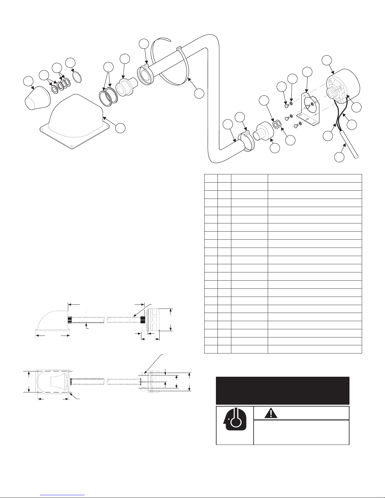
The Project-A-Flex® siren speaker allows the horn and
driver to be installed separately under the hood of even the
most compact vehicles. The speaker driver can be mounted
on the firewall or the fenderwall virtually any distance from
the horn. Through the use of acoustical flexible tubing, the
horn can be mounted behind the vehicles grille, under the
bumper or any other concealed location that will allow the
forward projection of sound. The acoustical flexible tubing
not only allows easier installation, but also substantially
increases the sound level gain.
TUBING MARKED
AT 4" INTERVALS
4.20 DIA
3.83"
.257 X .500 LONG
MOUNTING SLOT
(3) PLACES
6.38"
FLEXIBLE TUBING LENGTH
(SEE NOTE)
.120" DIAMETER
1.00"
13
12
15
14
10
2
8
9
3
21
11
22
QTY.
1
3
3
1
1
1
1
2
1
8
1
1
1
4
4
2
1
1
1
A/R
NOTE: Items 1 through 7 are factory pre-assembled as a complete speaker horn assembly.
PART NUMBER
ITEM
01-0860496-00
72-4010291-00
1
38-0220049-00
2
38-0220048-00
3
38-0220046-00
4
5
72-1080442-00
38-0220047-00
6
7
22-1340360-03
8
26-0111614-00
9
26-0911577-00
26-0215001-11
10
22-1340359-04
11
07-260490-010
12
43-0215884-04
13
NO T AVAI LA BL E
14
NO T AVAI LA BL E
15
19
22-0410510-00
67-1361699150
20
67-1361600150
21
26-0610158-00
22
23
66-1416020-00
DESCRIPTION
PROJECT-A-FLEX™ ASSY
SPEAKER CONE
RUBBER SEAL
FIBER SPACER SEAL
PAPER SEAL
SPEAKER FLARE
METAL GASKET
ADAPTER SPEAKER
HOSE CLAMP
FLEXIBLE TUBING
TY-WRAP
ADAPTER SPEAKER
MTG. BRKT - DRIVER
100 WATT DRIVER
1/4-20X1/2 HEX HD CAPSCREW
1/4" EXT TOOTH SST LOCKWASHER
TERMINAL CAP-PLASTIC / BLACK
1/C 16 GA. WIRE WHT 15" LG. W/FASTON
1/C 16 GA. WIRE BLK. 15" LG. W/FASTON
PVC TUBING-BLACK 6" LG
ANTI-SEIZE GREASE
19
20
4.850"
5.750"
.218" DIA HOLE
(4) PLACES
1.375"
2.75"
3.50"
Page 2
ACTIVATION OF THIS
SIREN MAY DAMAGE
UNPROTECTED EARS!
CAUTION
Loud siren noise can cause
Wear
Protection!
hearing damage and/or loss.
Refer to OSHA Section 1910.95 prior
to putting ANY siren into service!
Page 3
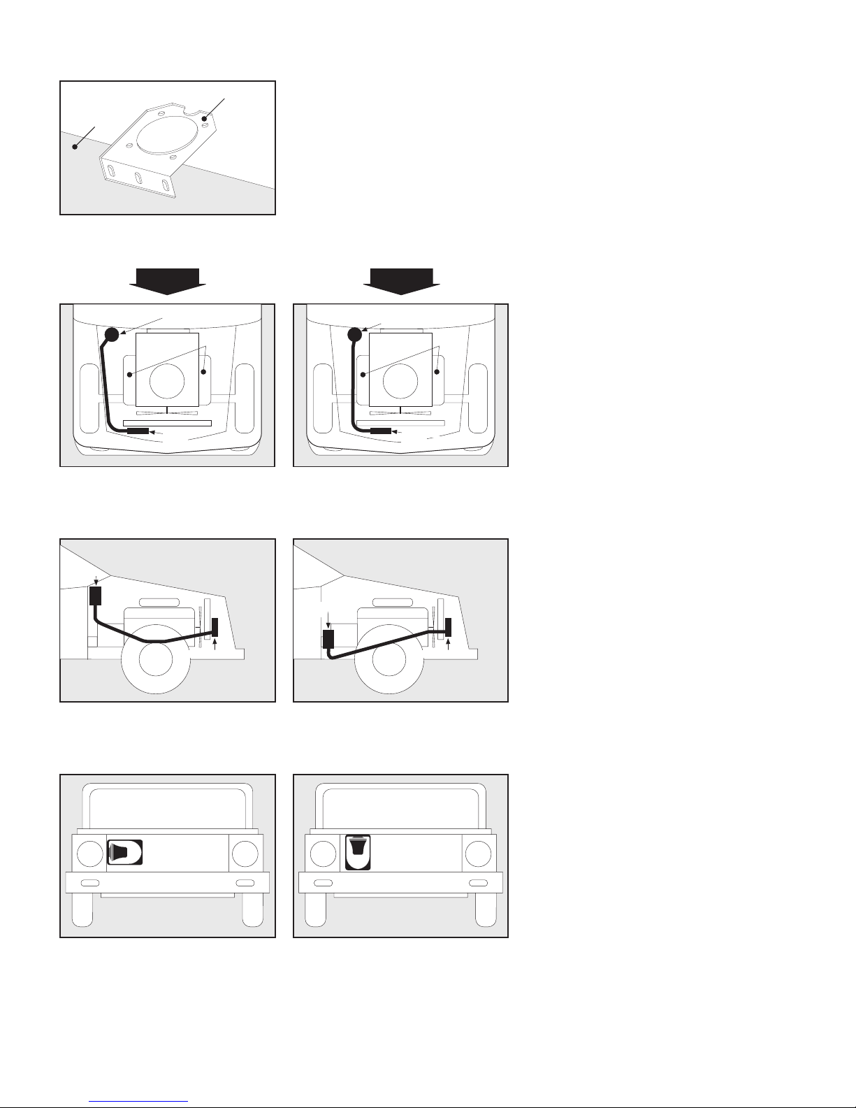
FIG. 1
The standard length of the acoustical flexible tubing is 60”, and is marked every
ENGINE FIREWALL,
FENDERWALL OR
OTHER SUITABLE
LOCATION.
SPEAKER
DRIVER
MOUNTING
BRACKET
(ITEM 13)
4” with a white dot. After installing the speaker driver and the speaker horn
assembly in the desired locations, cut the flexible acoustical tubing to fit properly
between these two units in the order as indicated in the drawing on this page. For
optimum sound levels, it is very important to cut the flexible tubing at the 4”
interval markings. example. If 46 inches of flexible tubing is desired, cut the tubing
at either the 44” or 48” length. Acousticle flexible tubing lengths greater than 60
inches are available on special order.
Choose desired mounting location
and mark the monting holes using
the bracket as a template.
DO
FIG. 2-A FIG. 2-B
SPEAKER
DRIVER
EXHAUST
MANIFOLDS
SPEAKER
HORN
Route acoustical flexible tubing away
from engine exhaust manifolds
or exaust pipe.
FIG. 3-A
SPEAKER
DRIVER
SPEAKER HORN SPEAKER HORN
Install speaker driver at a higher level
than the speaker horn. Drill a 1/8"
diameter hole on the bottom of the
acoustical tubing at the lowest point.
FIG. 4-A
Mount speaker horn in a horizontal
position to make sure water does
not collect inside the speaker tip.
DO NOT route acoustical flexible
tubing on or near engine exhaust
manifolds or tail pipe.
FIG. 3-B
SPEAKER
DRIVER
DO NOT Install speaker driver at a
lower level than the speaker horn.
water could enter speaker horn, be
trapped inside and damage speaker.
FIG. 4-B
DO NOT mount speaker horn in a
vertical position will allow water to
enter the speaker tip and cause
permanant failure.
DON’T
SPEAKER
DRIVER
SPEAKER
HORN
EXHAUST
MANIFOLDS
Installation Instructions:
1. Check the contents of the kit to insure that
all parts and components are in the
package. See exploded parts drawing on
front page.
2. Determine the ideal mounting location for
the driver and speaker horn assembly.
Follow diagrams on left.
3. After the location for the speaker driver
has been chosen, use the driver mounting
bracket as a template for making and
drilling the bracket mounting holes.
4. After the driver mounting bracket is
securely mounted to the vehicle, install the
speaker driver to the bracket using ¼” X
20 X ½” hex head cap screws.
5. Install the driver adapter (item 11) to the
speaker driver, making sure to insert the
rubber seal (item 2) and fiber spacer seal
(item 3) between the adapter and driver.
Continue the assembly process in the
sequence shown in the drawing on pg. 1.
6. Install the speaker horn assembly at the
chosen location on the front grill of the
vehicle (fig. 4). Speaker horn assembly
may be secured with the enclosed tywraps (item 10).
7. Route the acoustical flexible tubing from
the driver to the speaker horn assembly
following the warnings to the left. To fit the
acoustical tubing, cut it at the nearest 4”
length (see text at the top of the page).
8. Clamp the flexible acoustical tubing
securely over the speaker horn and driver
adapters with the two hose clamps (item
8). Use ty-wraps (item 10) to secure
acoustical tubing in place (figs. 2 & 3).
IMPORTANT: Due to the lightweight nature of
some plastic front grilles, when mounting the
speaker horn upon it, harmonic vibration
(distortion) of the siren sound is possible. In
this case use a mounting location for the
speaker horn other than the speaker grille
itself. Example: Grille Mounting Posts, Metal
Bumper Flanges, etc.
Page 3
 Loading...