

Page 1

®
ENGINEERING COMPANY INC.
51 Winthrop Road
Chester, Connecticut 06412-0684
PCC4W Power Control Center
Installation Guide:
Phone: (860) 526-9504
Fax: (860) 526-4078
Internet: www.whelen.com
Sales e-mail: autosale@whelen.com
Canadian Sales e-mail: canadiansales@whelen.com
Customer Service e-mail: custserv@whelen.com
DANGER! Sirens produce extremely loud emergency warning tones! Exposure to these
tones without proper and adequate hearing protection, could cause ear damage and/or hearing
loss! The Occupational Safety & Health Administration (www.osha.gov) provides information
necessary to determine safe exposure times in Occupational Noise Exposure Section 1910.95.
Until you have determined the safe exposure times for your specific application, operators and
anyone else in the immediate vicinity should be required to wear an approved hearing protection
device. FAILURE TO FOLLOW THIS RECOMMENDATION COULD CAUSE HEARING LOSS!
Safety First
This document provides all the necessary information to allow your Whelen product to be properly and safely installed.
Before beginning the installation and/or operation of your new product, the installation technician and operator must
read this manual completely. Important information is contained herein that could prevent serious injury or damage.
• Proper installation of this product requires the installer to have a good understanding of automotive electronics,
systems and procedures.
• If mounting this product requires drilling holes, the installer MUST be sure that no vehicle components or other
vital parts could be damaged by the drilling process. Check both sides of the mounting surface before drilling
begins. Also de-burr any holes and remove any metal shards or remnants. Install grommets into all wire
passage holes.
• If this manual states that this product may be mounted with suction cups, magnets, tape or Velcro®, clean the
mounting surface with a 50/50 mix of isopropyl alcohol and water and dry thoroughly.
• Do not install this product or route any wires in the deployment area of your air bag. Equipment mounted or
located in the air bag deployment area will damage or reduce the effectiveness of the air bag, or become a
projectile that could cause serious personal injury or death. Refer to your vehicle owner’s manual for the air bag
deployment area. The User/Installer assumes full responsibility to determine proper mounting location, based
on providing ultimate safety to all passengers inside the vehicle.
• For this product to operate at optimum efficiency, a good electrical connection to chassis ground must be
made. The recommended procedure requires the product ground wire to be connected directly to the NEGATIVE
(-) battery post.
• If this product uses a remote device to activate or control this product, make sure this control is located in an
area that allows both the vehicle and the control to be operated safely in any driving condition. DO NOT
ATTEMPT TO ACTIVATE OR CONTROL THIS DEVICE IN A HAZARDOUS DRIVING SITUATION.
• It is recommended that these instructions be stored in a safe place and
referred to when performing maintenance and/or reinstallation of this
product.
• FAILURE TO FOLLOW THESE SAFETY PRECAUTIONS AND
INSTRUCTIONS COULD RESULT IN DAMAGE TO THE PRODUCT OR
VEHICLE AND/OR SERIOUS INJURY TO YOU AND YOUR PASSENGERS!
ACTIVATION OF THIS
SIREN MAY DAMAGE
UNPROTECTED EARS!
CAUTION
Loud siren noise can cause
hearing damage and/or loss.
Wear
Refer to OSHA Section 1910.95 prior
Protection!
to putting ANY siren into service!
Automotive: Sirens/Switches
For warranty information regarding this product, visit www.whelen.com/warranty
©2011 Whelen Engineering Company Inc.
Form No.14492 (042811)
Page 1
Page 2
Model PCC4W
WARNING! These switches are suitable for 25 amp, 12 volt DC
applications. Any attempt to load these switches above 25 amps will
result in switch failure.
WARNING! All customer supplied wires that connect to the positive
terminal of the battery must be sized to supply at least 125% of the
maximum operating current and be FUSED
at the battery to carry
that load. DO NOT USE CIRCUIT BREAKERS WITH THIS PRODUCT!
Congratulations on selecting the PCC4W six switch power control center.
This product offers a unique and distinctive collection of features.
Features include:
• Ignition controlled LED backlighting
• Compact design
• Switch 'active' LED indicators
• Four 25 amp switches
• 72 switch function labels
Mounting:
An aftermarket center console is recommended for the mounting location
of the PCC4W. This not only allows the driver to reach the controls easily,
but also keeps the unit safely out of the path of the vehicle’s SRS air-bag.
Follow the console manufacturer’s instructions for mounting information. If
a console-type mount is not possible, the PCC4W includes a bail strap
mounting kit for over or under dash mounting.
WARNING: Regardless of the style selected, be sure to observe the
air-bag warning on the cover of this manual.
WARNING: Mounting this unit will require drilling. It is absolutely
necessary to make sure that no other vehicle components could be
damaged in the process. Check both sides of the mounting surface
before starting. If damage is likely, select a different location.
Bail Strap Mount:
1. Position the bail strap in the selected mounting location. Using an
awl or other suitable tool, scribe the surface where the mounting
holes are to be drilled.
2. Carefully drill the mounting
holes in the areas scribed
in step one. The size of the
drill bit should be
determined by the size of
the mounting hardware
(customer supplied) and
the thickness of the
mounting surface.
SW1
3. Using the customer
supplied mounting
hardware, secure the bail strap to the mounting location.
►
SW4
Screw
Console Mount:
Console manufacturers offer mounting kits that include all the necessary
hardware and brackets required to mount this unit into their console. The
console mount brackets are secured onto the unit the same way the bail
bracket is. Refer to the manual included with your console.
Function Labels: Take the supplied label kit and determine which label
describes the function of switch 1. Peel the label off the backing and place
it in the label window above switch 1. Press the label lightly into place.
Repeat for each switch.
Wiring:
BLACK WIRE: This wire supplies ground to both the units function
window backlighting and the switch 'active' LED indicators located on the
front of each switch. This wire can be connected to any vehicle ground
that can supply 100ma.
WHITE/YELLOW WIRE: This wire supplies power to the units window
backlighting. This wire can be connected to any ignition controlled +VBAT
power source that can supply 100ma. NOTE: If your PCC4W does not
have a white/yellow wire, then it is not equipped with the
backlighting feature.
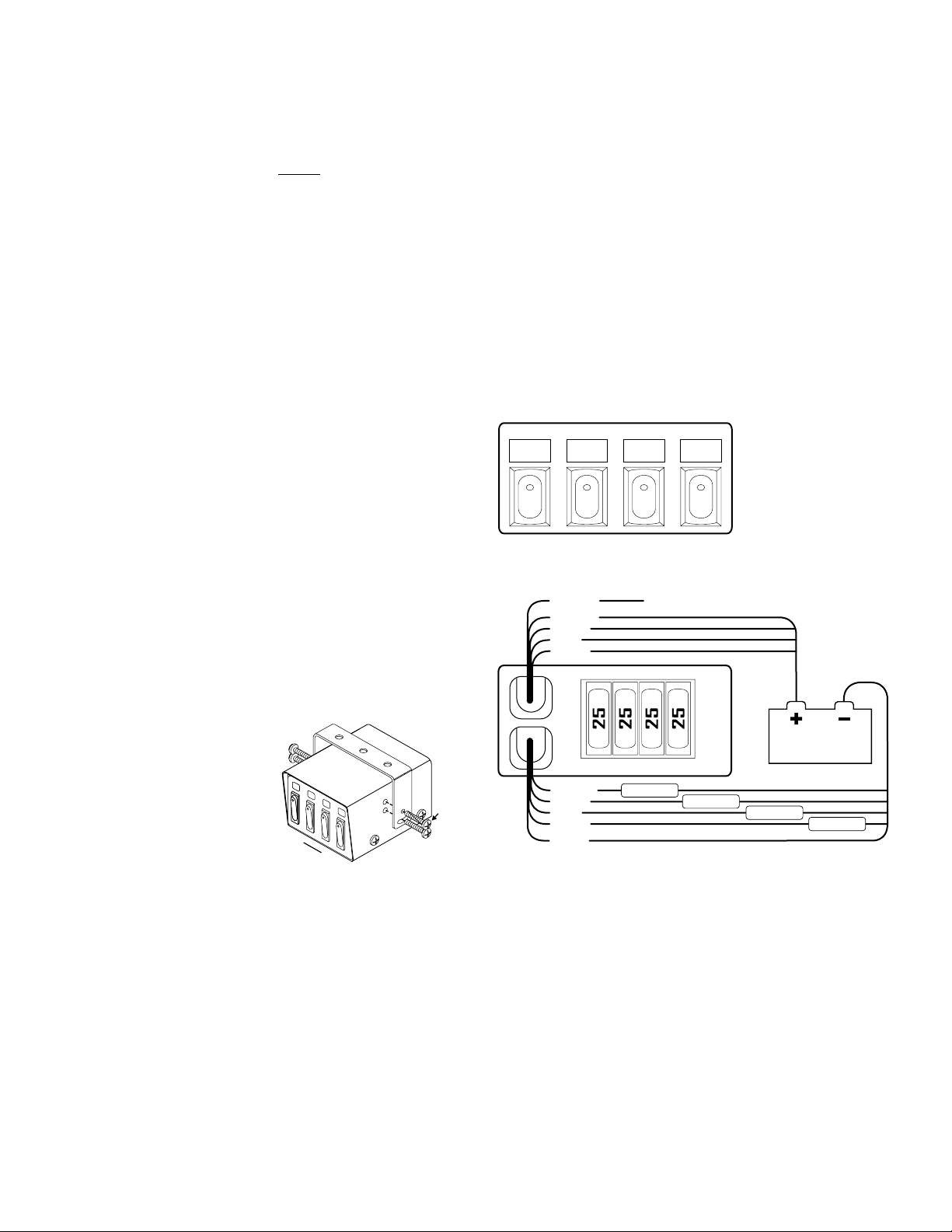
WIRING
DIAGRAM
FRONT VIEW
SW1:
yellow
wires
IMPORTANT: It is the responsibility of the installation technician to
make sure that the installation and operation of this product will not
interfere with or compromise the operation or efficiency of any vehicle equipment! Before returning the vehicle to active service, visually confirm the proper operation of this product.
SW2:
green
wires
WHT/YEL
YELLOW
GREEN
BLUE
VIOLET
YELLOW
GREEN
BLUE
VIOLET
BLACK
SW3 SW2 SW1
SW4
25 AMP FUSES
SW3
blue
wires
LOAD
SW4
violet
wires
Connect to +VBAT ignition controlled 100ma power source
LOAD
BATTERY
LOAD
REAR VIEW
LOAD
Page 2
 Loading...