

Page 1

®
ENGINEERING COMPANY INC.
51 Winthrop Road
Chester, Connecticut 06412-0684
500 Series LED Lighthead
Installation Guide:
Phone: (860) 526-9504
Fax: (860) 526-4078
Internet: www.whelen.com
Sales e-mail: autosale@whelen.com
Canadian Sales e-mail: autocan@whelen.com
Customer Service e-mail: custserv@whelen.com
Safety First
This document provides all the necessary information to allow your Whelen product to be properly and safely installed.
Before beginning the installation and/or operation of your new product, the installation technician and operator must
read this manual completely. Important information is contained herein that could prevent serious injury or damage.
• Proper installation of this product requires the installer to have a good understanding of automotive electronics,
systems and procedures.
• If mounting this product requires drilling holes, the installer MUST be sure that no vehicle components or other
vital parts could be damaged by the drilling process. Check both sides of the mounting surface before drilling
begins. Also de-burr any holes and remove any metal shards or remnants. Install grommets into all wire
passage holes.
• If this manual states that this product may be mounted with suction cups, magnets, tape or Velcro®, clean the
mounting surface with a 50/50 mix of isopropyl alcohol and water and dry thoroughly.
• Do not install this product or route any wires in the deployment area of your air bag. Equipment mounted or
located in the air bag deployment area will damage or reduce the effectiveness of the air bag, or become a
projectile that could cause serious personal injury or death. Refer to your vehicle owner’s manual for the air bag
deployment area. The User/Installer assumes full responsibility to determine proper mounting location, based
on providing ultimate safety to all passengers inside the vehicle.
• For this product to operate at optimum efficiency, a good electrical connection to chassis ground must be
made. The recommended procedure requires the product ground wire to be connected directly to the NEGATIVE
(-) battery post.
• If this product uses a remote device to activate or control this product, make sure that this control is located in
an area that allows both the vehicle and the control to be operated safely in any driving condition.
• Do not attempt to activate or control this device in a hazardous driving situation.
• This product contains either strobe light(s), halogen light(s), high-intensity LEDs or a combination of these
lights. Do not stare directly into these lights. Momentary blindness and/or eye damage could result.
• Use only soap and water to clean the outer lens. Use of other chemicals could result in premature lens cracking
(crazing) and discoloration. Lenses in this condition have significantly reduced effectiveness and should be
replaced immediately. Inspect and operate this product regularly to confirm its proper operation and mounting
condition. Do not use a pressure washer to clean this product.
• It is recommended that these instructions be stored in a safe place and referred to when performing
maintenance and/or reinstallation of this product.
• FAILURE TO FOLLOW THESE SAFETY PRECAUTIONS AND INSTRUCTIONS COULD RESULT IN DAMAGE TO
THE PRODUCT OR VEHICLE AND/OR SERIOUS INJURY TO YOU AND YOUR PASSENGERS!
Automotive: Lightheads
For warranty information regarding this product, visit www.whelen.com/warranty
©2001 Whelen Engineering Company Inc.
Form No.13584K (072408)
Page 1
Page 2
IMPORTANT NOTICE! Prior to installing this
product on any vehicle, check your state
motor vehicle codes to confirm that this
product complies with all state statutes.
Installation:
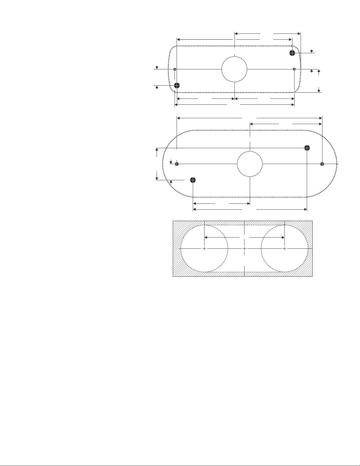
1. First, mark the mounting, wire access and vent
holes using the measurements shown. Drill the
holes to the sizes noted.
.637"
MTG. HOLE
FOR #6 SMS
1/4" DIA.
VENT HOLE
2.597"
4.527"
500 Series / Non-Flanged
1" DIAMETER
WIRE. HOLE
1/4" DIA.
VENT HOLE
MTG. HOLE
FOR #6 SMS
.637"
.912"
IMPORTANT: Templates are not to scale. Check all
measurements before drilling.
2. Thread the wires through the rubber gasket, through
the wire access hole and to your power source. Use
a rubber grommet (customer supplied) to protect the
wires from the edge of the wire access hole.
Wire designations are listed on the next page.
3. Attach light to vehicle using the supplied hardware.
4. Connect the lighthead wires to your power source.
IMPORTANT: Any customer supplied wire must be
a minimum of 22 gauge.
NOTE: This product draws significantly less
current than a standard automotive bulb. If your
flasher does not operate properly, it may be
necessary to replace your existing flasher module
with a Whelen 3TERM flasher module. Contact
your sales representative for specific vehicle
information.
Pattern Selection:
WARNING: PATTERN SELECTION REQUIRES THE
LED TO BE TURNED ON. DO NOT LOOK
DIRECTLY AT LEDs WHILE UNIT IS IN
OPERATION.
1.274"
MTG. HOLE
FOR #10
SCREW
.637"
MOUNTING SURFACEMOUNTING SURFACE
2.264"
1/4" DIA.
VENT HOLE
1.25" RADIUS
4.690"
2.345"
5.750"
500 Series / Flanged
1" DIAMETER
WIRE. HOLE
2.264"
4.527"
4.25"
500 Series
D.O.T. Grommet
2.875"
1.25" RADIUS
1/4" DIA.
VENT HOLE
MTG. HOLE
FOR #10
SCREW
PATTERN SELECTION PROCEDURE / Scan-Lock™:
Locate the WHITE-VIOLET (Scan-Lock™) wire then turn the lighthead on.
TO CYCLE FORWARD THROUGH PATTERNS: Apply +VBAT to the WHT/VIO wire for less than 1 second and release. Repeat to advance to the next
pattern.
TO CHOOSE A PATTERN: While cycling through patterns, allow a pattern to run for more than 5 seconds. This will become the default pattern.
TO CYCLE BACKWARDS THROUGH PATTERNS: Apply +VBAT to the WHT/VIO wire for more than 1 second and release.
TO RESET THE LIGHTHEAD TO THE DEFAULT PATTERN: Turn the lighthead off. While applying +VBAT to the WHT/VIO wire, turn the lighthead on.
Continue to apply voltage until the default pattern is active (approximately 3 seconds).
AVAILABLE FLASH PATTERNS:
1. SignalAlert™ 75
2. SignalAlert 150
3. SingleFlash 375
4. SingleFlash 150
5. SingleFlash 75
6. SingleFlash 15
7. DoubleFlash 150
8. DoubleFlash 75
9. CometFlash® 75
10. ActionFlash™
11. ModuFlash™
12. ComAlert™
13. ActionScan™
14. SignalAlert Steady
15. Steady (Brake)
Page 2
Page 3

Part Number Key:
Flanged:
STYLE
0=
5=
7=
8=
B=
G=
H=
E=
K=
LED & LENS COLOR
A=
B=
C=
G=
R=
1=
2=
4=
5=
TERMINATION
0=NONE
___01-0683558
TERMINATION
LENS/LED COLOR
STYLE
STEADY
WIDE ANGLE
BACK-UP
CLEARANCE
BRAKE/TAIL/TURN (MAX)
BACK-UP (24V)
GROUND LIGHT
BRAKE/TAIL/TURN (MAX) 24VOLT
WIDE-ANGLE (24V)
AMBER / AMBER
BLUE / BLUE
WHITE / CLEAR
GREEN / GREEN
RED / RED
AMBER / CLEAR
BLUE / CLEAR
GREEN / CLEAR
RED / CLEAR
QTY QTY QTY QTY QTY QTY QTY QTY QTY QTY QTY
*
*
*
*
*
*
*
*
*
*
*
2
1
A/R
A/R
A/R
A/R
111
A/R
A/R
A/R
A/R
A/R
1
1
A/R
11
A/R
1
A/R
A/R
1
1 111
1
1
1 1
1
1
1
1
1
1
2222222222
A/R
A/RA/R
A/R
A/R
A/R
A/R
A/R
A/R
A/R
A/R
A/R
A/R
A/R
A/R
A/R
A/R
A/R
A/R
A/R
A/R
1
ITEM
PART NUMBER
01-06835580 0__
01-06835585 0__
01-06835587C0
01-06835588 0__
01-0683558BR0
01-0683558BA0
01-0683558HC0
01-0683558GC0
01-0683558K__0
01-0683558ER0
01-0683558EA0
15-065419-060
1
68-3963228-10
2
68-3963228-30
3
68-3963228-50
4
68-1963583-10
5
68-1963583-20
6
68-1963583-30
7
68-1963583-40
8
68-1963583-50
9
01-0263265-10
10
01-0263265-20
11
01-0263265-30
12
01-0263265-40
13
01-0263265-50
14
01-0263265-15
15
01-0263265-25
16
01-0263265-35
17
01-0263265-45
18
01-0263265-55
19
01-0263265-37
20
01-0263314-11
21
01-0263314-51
22
01-0263265-5B
23
10-0522795-__
24
01-0263265-1B
25
01-0263265-39
26
68-1963546-30
27
01-0263265-3G
28
68-1963428-30
29
01-0263265-1K
30
01-0263265-2K
31
01-0263265-3K
32
01-0263265-4K
33
01-0263265-5K
34
01-0263265-5E
35
01-0263265-1E
36
LIGHTHEAD 500 LED FLANGED STEADY/
DESCRIPTION
LIGHTHEAD 500 LED FLANGED WIDE ANGLE/
LIGHTHEAD 500 LED FLANGED BACK-UP WHITE/
LIGHTHEAD 500 LED FLANGED CLEARANCE
LIGHTHEAD 500 LED FLANGED BRAKE TAIL TURN MAX// ( )
LIGHTHEAD 500 LED FLANGED MARKER/TURN AMBER/
LIGHTHEAD 500 LED FLANGED GROUND LIGHT WHITE/
LIGHTHEAD 500 LED FLANGED BACK-UP 24V WHITE//
LIGHTHEAD 500 LED FLANGED WIDE ANGLE 24V()
LIGHTHEAD 500 LED FLANGED BRAKE TAIL TURN MAX 24V// ( -)
LIGHTHEAD 500 LED FLANGED MARKER-TURN AMBER 24V/()
SCREW #6 X 3/8" PPH PLASTI-LOC/
LENS NON OPTIC AMBER//
LENS NON OPTIC CLEAR//
LENS NON OPTIC RED//
LENS OPTIC AMBER//
LENS OPTIC BLUE//
LENS OPTIC CLEAR//
LENS OPTIC GREEN//
LENS OPTIC RED//
SUB ASSY 500 LED FLANGED STEADY AMBER//
SUB ASSY 500 LED FLANGED STEADY BLUE//
SUB ASSY 500 LED FLANGED STEADY WHITE//
SUB ASSY 500 LED FLANGED STEADY GREEN//
SUB ASSY 500 LED FLANGED STEADY RED//
SUB ASSY 500 LED FLANGED FLASHER AMBER//
SUB ASSY 500 LED FLANGED FLASHER BLUE//
SUB ASSY 500 LED FLANGED FLASHER WHITE//
SUB ASSY 500 LED FLANGED FLASHER GREEN//
SUB ASSY 500 LED FLANGED FLASHER RED//
SUB ASSY 500 LED FLANGED BACK-UP WHITE//
SUB ASSY 500 LED FLANGED CLEARANCE AMBER//
SUB ASSY 500 LED FLANGED CLEARANCE RED//
SUB ASSY 500 LED FLANGED BRAKE TAIL TURN MAX///()
LABEL MODEL 500 LED FLANGED not shown//
SUB ASSY 500 LED FLANGED MARKER-TURN AMBER//
SUB ASSY 500 LED FLANGED COMP GROUND WHITE///
LENS OPTIC SCENE CLEAR//
SUB ASSY 500 LED FLANGED BACK-UP 24V WHITE///
LENS OPTIC 45° CLEAR//
SUB ASSY 500 LED FLANGED FLASHER AMBER 24V///
SUB ASSY 500 LED FLANGED FLASHER BLUE 24V///
SUB ASSY 500 LED FLANGED FLASHER WHITE 24V///
SUB ASSY 500 LED FLANGED FLASHER GREEN 24V///
SUB ASSY 500 LED FLANGED FLASHER RED 24V///
SUB ASSY 500 LED FLANGED BRAKE-TAIL-TURN MAX 24V///
SUB ASSY / 500 LED FLANGED MARKER TURN AMBER 24V// /
Wiring:
Brake-Tail
-Turn 24V
Marker
-Turn 24V
Back-Up
24V
Brake-Tail
-Turn 12V
Steady 12V
Wide Angle
12V
WHT-VIO Scan-Lock™
BROWN +24VDC - TAIL
YELLOW +24VDC - STOP/TURN
WHT-BLK
(-) GROUND
WHT-VIO Scan-Lock
BROWN +24VDC - LOW POWER
GREEN +24VDC - HIGH POWER
WHT-BLK
(-) GROUND
WHITE +24VDC
BLK-WHT (-) GROUND
WHT-VIO Scan-Lock
BROWN +12VDC - TAIL
YELLOW +12VDC - STOP-TURN
WHITE
(-) GROUND
LED Color +12VDC
BLACK (-) GROUND
WHT-VIO Scan-Lock
LED Color +12VDC
BLACK (-) GROUND
21 22
27
OPTIONAL:
FLANGE KIT / BLACK
01-0463297-00
FLANGE KIT / CHROME
01-0463297-01
FLANGE KIT
POLISHED ALUMINUM
01-0463297-02
Wide Angle
24V
WHT-VIO Scan-Lock
LED Color +24VDC
BLK-WHT (-) GROUND
Page 3
DOT MOUNTING KIT
25
352336
26
2 3 4
1
5678929
(OPTIONAL)
P/N 01-0463308-00
30 31 32
10 11 12 13 14 15
1630173118321933203428
Page 4

500 SERIES LED
Specifications
BRAKE / TAIL / TURN
LED Assembly
Input Voltage
Input Current / Tail
Input Current / Brake
Default Pattern
BACK-UP / 12VDC
Input Voltage
Input Current
Default Pattern
BACK-UP / 24VDC
Input Voltage
Input Current
Default Pattern
FLASHER
Input Voltage
Input Current
Default Pattern
STEADY
Input Voltage
Input Current
Default Pattern
Part Number Key:
Non-Flanged:
STYLE
0=
5=
7=
8=
9=
B=
G=
H=
E=
K=
LED & LENS COLOR
A=
B=
C=
G=
R=
1=
2=
4=
5=
NUMBER OF LED's
(COMPARTMENT)
1=
2=
4=
7=
TERMINATION
0=1=NONE
___01-0683557
STEADY
WIDE-ANGLE
BACK-UP
CLEARANCE
COMPARTMENT
BRAKE/TAIL/TURN (MAX)
BACK-UP 24V
GROUND LIGHT
BRAKE/TAIL/TURN (MAX) 24VOLT
WIDE ANGLE 24 VOLT
AMBER / AMBER
BLUE / BLUE
WHITE / CLEAR
GREEN / GREEN
RED / RED
AMBER / CLEAR
BLUE / CLEAR
GREEN / CLEAR
RED / CLEAR
12
24
48
72
DEUTSCH
44 LEDs
12 8 VDC
.
±20%
0 235 AMPS
.
0 035 AMPS
.
™
SignalAlert Brake
12.8 VDC ±20%
0.320 AMPS
Steady
25.6 VDC ±20%
0.160 AMPS
Steady
12 8 VDC ±20%.
0 235 AMPS
.
™
SignalAlert 75
12 8 VDC ±20%
.
0 30 AMPS
.
Steady
TERMINATION or
NUMBER of LEDs
LENS/LED COLOR
STYLE
QTY QTY QTYQTY QTY QTY QTY QTY QTY QTY QTY QTY
QTYQTY
*
*
*
*
*
*
*
*
1
A/R
A/R
A/R
A/R
A/R
A/R
A/R
A/R
A/R
A/R
1
222
1
1
1
1
1
1
11
11
11
A/R
A/R
1 1
111
11
1
1
1
1
1
1
1
1
*
*
*
*
111
1
A/R
1
A/R
A/R
1
1
1
11111111
1
1 111
1
A/R
A/R
QTY
ITEM
PART NUMBER
1
2
3
4
5
6
7
8
9
10
11
12
13
14
15
16
17
18
19
20
21
22
23
24
25
26
27
28
29
1111
30
31
32
33
34
35
36
37
38
39
40
41
42
43
44
01-06835570__0
01-06835575__0
01-06835577C___
01-06835578__0
01-0683557BR0
01-06835579C1
01-06835579C2
01-06835579C4
01-06835579C7
01-06835579C0
01-0683557HC0
01-06835575__1
01-0683557GC___
01-0683557K__0
01-0683557ER0
15-061416-200
68-3963228-10
68-3963228-10
68-3963228-30
68-3963228-10
68-3963228-50
68-1963583-10
68-1963583-20
68-1963583-30
68-1963583-40
68-1963583-50
01-0263309-10
01-0263309-20
01-0263309-30
01-0263309-40
01-0263309-50
01-0263309-15
01-0263309-25
01-0263309-35
01-0263309-45
01-0263309-55
01-0263309-37
01-0263314-12
01-0263314-52
01-0263309-5B
01-0263316-12
01-0263316-24
01-0263316-48
01-0263316-72
10-0522797-__
38-0222786-00
01-0263309-39
68-1963546-30
02-0363309155
02-0363309137
01-0263309-3G
02-036330913G
68-1963428-30
01-0263309-1K
01-0263309-2K
01-0263309-3K
01-0263309-4K
01-0263309-5K
01-0263309-5E
*
*
*
222222222222
A/RA/R
A/R
A/R
A/R
A/R
A/R
A/R
A/R
A/R
A/R
A/R
A/R
A/R
A/R
A/R
A/R
A/R
A/R
A/R
A/R
A/R
LIGHTHEAD 500 LED NON-FLANGED, STEADY
LIGHTHEAD 500 LED NON-FLANGED WIDE ANGLE,-
LIGHTHEAD 500 LED NON-FLANGED BACK-UP, WHITE
LIGHTHEAD 500 LED NON-FLANGED CLEARANCE,
LIGHTHEAD 500 LED NON-FLANGED BRAKE TAIL TURN MAX,//()
LIGHTHEAD 500 LED NON-FLANGED COMPARTMENT 12 LEDs WHITE,()
LIGHTHEAD 500 LED NON-FLANGED COMPARTMENT 24 LEDs WHITE,()
LIGHTHEAD 500 LED NON-FLANGED COMPARTMENT 48 LEDs WHITE,()
LIGHTHEAD 500 LED NON-FLANGED COMPARTMENT 72 LEDs WHITE,()
LIGHTHEAD 500 LED NON-FLANGED COMPARTMENT WHITE()
LIGHTHEAD 500 LED NON-FLANGED GROUND LIGHT WHITE()
LIGHTHEAD 500 LED NON-FLANGED WIDE ANGLE DEUTSCH()
LIGHTHEAD 500 LED NON-FLANGED BACK-UP 24V WHITE,( )
LIGHTHEAD 500 LED NON-FLANGED, WIDE ANGLE (24V)
LIGHTHEAD 500 LED NON-FLANGED BRAKE TAIL TURN MAX 24V,//(-)
SCREW #6 X 1-1/4" PPH SHEET METAL/
LENS NON OPTIC AMBER//
LENS NON OPTIC BLUE//
LENS NON OPTIC CLEAR//
LENS NON OPTIC GREEN//
LENS NON OPTIC RED//
LENS OPTIC AMBER//
LENS OPTIC BLUE//
LENS OPTIC CLEAR//
LENS OPTIC GREEN//
LENS OPTIC RED//
SUB ASSY 500 LED NON-FLANGED STEADY AMBER/()
SUB ASSY 500 LED NON-FLANGED STEADY BLUE/()
SUB ASSY 500 LED NON-FLANGED STEADY WHITE/()
SUB ASSY 500 LED NON-FLANGED STEADY GREEN/()
SUB ASSY 500 LED NON-FLANGED STEADY RED/()
SUB ASSY 500 LED NON-FLANGED WIDE ANGLE AMBER/-()
SUB ASSY 500 LED NON-FLANGED WIDE ANGLE BLUE/-()
SUB ASSY 500 LED NON-FLANGED WIDE ANGLE WHITE/-()
SUB ASSY 500 LED NON-FLANGED WIDE ANGLE GREEN/-()
SUB ASSY 500 LED NON-FLANGED WIDE ANGLE RED/-()
SUB ASSY 500 LED NON-FLANGED BACK-UP WHITE/()
SUB ASSY 500 LED NON-FLANGED CLEARANCE AMBER/()
SUB ASSY 500 LED NON-FLANGED CLEARANCE RED/()
SUB ASSY 500 LED NON-FLANGED BRAKE TAIL TURN MAX///()
SUB ASSY 500 LED NON-FLANGED COMPARTMENT 12 LEDs WHITE/,()
SUB ASSY 500 LED NON-FLANGED COMPARTMENT 24 LEDs WHITE/,()
SUB ASSY 500 LED NON-FLANGED COMPARTMENT 48 LEDs WHITE/,()
SUB ASSY 500 LED NON-FLANGED COMPARTMENT 72 LEDs WHITE/,()
LABEL
GASKET
SUB ASSY 500 LED NON-FLANGED COMPARTMENT WHITE/()
LENS OPTIC SCENE - CLEAR/
SUB ASSY 500 LED NON-FLANGED WIDE ANGLE RED DEUTSCH/-(-)
SUB ASSY 500 LED NON-FLANGED BACK-UP WHITE DEUTSCH/(-)
SUB ASSY 500 LED NON-FLANGED BACK-UP 24V WHITE/,()
SUB ASSY 500 LED NON-FLANGED BACK-UP 24V WHITE DEUTSCH/,(-)
LENS OPTIC 45° CLEAR//
LENS OPTIC SCENE - CLEAR/
SUB ASSY 500 LED NON-FLANGED WIDE ANGLE RED DEUTSCH/-(-)
SUB ASSY 500 LED NON-FLANGED BACK-UP WHITE DEUTSCH/(-)
SUB ASSY 500 LED NON-FLANGED BACK-UP 24V WHITE/,()
SUB ASSY 500 LED NON-FLANGED BACK-UP 24V WHITE DEUTSCH/,(-
LENS OPTIC 45° CLEAR//
DESCRIPTION
Wiring:
Brake-Tail
-Turn 24V
Back-Up
24V
Brake-Tail
-Turn 24V
Steady 12V
Wide Angle
12V
WHT-VIO Scan-Lock™
BROWN +24VDC - TAIL
YELLOW +24VDC - STOP/TURN
WHT-BLK
(-) GROUND
WHITE +24VDC
BLK-WHT (-) GROUND
BROWN +12VDC - TAIL
YELLOW
WHITE (-) GROUND
+12VDC - STOP/TURN
LED Color +12VDC
BLACK (-) GROUND
WHT-VIO Scan-Lock
LED Color +12VDC
BLACK (-) GROUND
Wide Angle
24V
23 24
33
1
2 3 4
5 6
WHT-VIO Scan-Lock
LED Color +24VDC
BLK-WHT (-) GROUND
Page 4
12
15 16
9
31
14
13
25
26 27
28 29
38710811
19 22
17 20
18 21
35 36 37 41 42 4339 40
32 34
 Loading...