


Automotive: Sirens/Switches
® |
|
ENGINEERING COMPANY INC. |
|
51 Winthrop Road |
Installation/Operating Guide: |
Chester, Connecticut 06412-0684 |
Dual Siren Control Head & Amp |
Phone: (860) 526-9504 |
295HFSA7 Flush Mount |
Fax: (860) 526-4078 |
295HFSA8 Console Mount |
Internet: www.whelen.com |
|
Sales e-mail: autosale@whelen.com |
|
Canadian Sales e-mail: canadiansales@whelen.com |
|
Customer Service e-mail: custserv@whelen.com |
|
DANGER! Sirens produce extremely loud emergency warning tones! Exposure to these tones without
proper and adequate hearing protection, could cause ear damage and/or hearing loss! The Occupational Safety & Health Administration (www.osha.gov) provides information necessary to determine safe exposure times in Occupational Noise Exposure Section 1910.95. Until you have determined the safe exposure times for your specific application, operators and anyone else in the immediate vicinity should be required to wear an approved hearing protection device. FAILURE TO FOLLOW THIS RECOMMENDATION COULD CAUSE HEARING LOSS!
Safety First
This document provides all the necessary information to allow your Whelen product to be properly and safely installed. Before beginning the installation and/or operation of your new product, the installation technician and operator must read this manual completely. Important information is contained herein that could prevent serious injury or damage.
•Proper installation of this product requires the installer to have a good understanding of automotive electronics, systems and procedures.
•Failure to use specified installation parts and/or hardware will void the product warranty!
•If mounting this product requires drilling holes, the installer MUST be sure that no vehicle components or other vital parts could be damaged by the drilling process. Check both sides of the mounting surface before drilling begins. Also de-burr any holes and remove any metal shards or remnants. Install grommets into all wire passage holes.
•If this manual states that this product may be mounted with suction cups, magnets, tape or Velcro®, clean the mounting surface with a 50/50 mix of isopropyl alcohol and water and dry thoroughly.
•Do not install this product or route any wires in the deployment area of your air bag. Equipment mounted or located in the air bag deployment area will damage or reduce the effectiveness of the air bag, or become a projectile that could cause serious personal injury or death. Refer to your vehicle owner’s manual for the air bag deployment area. The User/Installer assumes full responsibility to determine proper mounting location, based on providing ultimate safety to all passengers inside the vehicle.
•For this product to operate at optimum efficiency, a good electrical connection to chassis ground must be made. The recommended procedure requires the product ground wire to be connected directly to the NEGATIVE (-) battery post.
•If this product uses a remote device to activate or control this product, make sure this control is located in an area that allows both the vehicle and the control to be operated safely in any driving condition. DO NOT ATTEMPT TO ACTIVATE OR CONTROL THIS DEVICE IN A HAZARDOUS DRIVING SITUATION.
• It is recommended that these instructions be stored in a safe place and |
ACTIVATION |
OF |
THIS |
referred to when performing maintenance and/or reinstallation of this |
SIREN MAY |
DAMAGE |
|
product. |
UNPROTECTED |
EARS! |
|
|
|
|
|
• FAILURE TO FOLLOW THESE SAFETY PRECAUTIONS AND |
|
|
|
CAUTION |
|
|
|
|
|
||
|
|
|
Loud siren noise can cause |
||
INSTRUCTIONS COULD RESULT IN DAMAGE TO THE PRODUCT OR |
|
|
|
||
|
|
|
hearing damage and/or loss. |
||
Wear |
|||||
VEHICLE AND/OR SERIOUS INJURY TO YOU AND YOUR PASSENGERS! |
Refer to OSHA Section 1910.95 prior |
||||
Protection! |
|||||
to putting ANY siren into service! |
|||||
For warranty information regarding this product, visit www.whelen.com/warranty
©2004 Whelen Engineering Company Inc.
Form No.13946G (053012)
Page 1

Congratulations on selecting the 295HFSA7 / 295HFSA8 Siren! This product offers a unique and distinctive collection of features designed to allow the user to customize the operation of this siren to suit their individual wants or needs.
•8 Programmable operating profiles
•Switch or ignition activated panel illumination.
•Stereo (dual) or mono sound control.
•200 Watts of output power.
•Removable microphone.
•“Siren In Use” output signal.
•Hands-Free operation.
•Radio Repeat.
•Simulated mechanical siren tones.
•Harmonically-rich, composite Airhorn tones.
•Title 13-compliant profiles.
•Independent, non-destructive short circuit protection.
Installation: Control Head
Important: Mounting will require drilling. It is absolutely necessary to make sure that no vehicle components behind the mounting area will be damaged. If damage is possible, Select another location.
Installation: There are two mounting styles for the siren control head depending on the model purchased.
Mounting Bracket
P/N 07-241559-000
Installation Kit 
P/N 01-0463232-00 

Control Head / Flush Mount |
Control Head |
P/N 01-0269919-00 |
Console Mount |
Siren Input Connector |
P/N 01-0269199-01 |
P/N 46-0746511-00 |
|
Siren Input Connector
P/N 46-0746511-00
Flush Mount |
Bail Strap Mount |
Flush Mount: The flush mount unit can be mounted in a console or other location. Using the measurements below, cut the hole for the control head, then slide the unit in. Mark and drill the four mounting holes for the customer supplied mounting hardware.
Bail Strap Mount: This unit uses a bail strap that can be attached under the dash. Follow the diagram above for assembly of the bracket. You will need to supply the screws that attach the bracket to the vehicle.
1.875" 1-7/8”
SIDE VIEW
25".2
5.5"
CUT-OUT THIS AREA
For Flush Mounting Only
IMPORTANT: Template not to scale.
1.35” |
Mounting Screws (Qty. 4) |
|
Page 2
Installation: Amplifier
1.Locate a suitable mounting location for the amplifier. The vertical wall between the trunk and the passenger compartment is often a good choice and is the method discussed in this manual.
2.Be sure that the amplifier fits properly and does not interfere with any parts of the trunk lid or seat back.
3.Position the amplifier on the proposed mounting location. Using an awl or other suitable tool, scribe the mounting surface where the mounting holes are to be drilled.
CAUTION! As mounting the amplifier will require drilling, it is absolutely necessary to make sure that no other vehicle components could be damaged by the drilling process. If any vehicle component could suffer any potential harm, select a different mounting location.
4.Carefully drill the mounting holes using a drill bit sized for a #10 sheet metal screw.
5.Using the supplied #10 x 3/4” sheet metal screws, secure the remote amplifier to the vertical trunk wall.
Wiring
Connecting to Power:
1.Using appropriately sized wire, extend the RED and BLACK wires from the Main Power Connector, through the firewall and into the engine compartment (refer to the Wire Gage Calculation Chart located on the last page of this manual to determine the proper wire size for your application).
2.Follow the factory wiring harness towards your vehicle’s battery.
WARNING! All customer supplied wires that connect to the positive terminal of the battery must be sized to supply at least 125% of the maximum operating current and FUSED at the battery to carry that load. DO NOT USE CIRCUIT BREAKERS WITH THIS PRODUCT!
3.Install a user supplied 20A fuse block on the end of the RED wire. Connect the fuse block to the battery using no more than 2 feet of wire. Do not install the fuse into the fuse holder yet!
4.Connect the BLACK wire directly to the NEGATIVE battery terminal.
Connecting to your Speaker(s):
1.Route the ORANGE, and BROWN wires from both Siren Connector #1 and Siren Connector #2 along the factory wiring harness towards your speakers.
2.Connect the ORANGE wire from Siren Connector #1 to the POSITIVE (+) terminal on speaker #1. Connect the ORANGE wire from Siren Connector #2 to the POSITIVE (+) terminal on speaker #2.
3.Connect the BROWN wire from Siren Connector #1 to the NEGATIVE (-) terminal on speaker #1. Connect the BROWN wire from Siren Connector #2 to the NEGATIVE (-) terminal on speaker #2.
Hands-Free Siren (optional):
Refer to the wiring diagram for all wiring information for this optional connection.
Radio Rebroadcast (optional):
The two (2) BLUE wires are used to connect your two-way radio’s external speaker for radio rebroadcast. This is an optional connection and will not effect the other operations.
Note: Radio rebroadcast will NOT work with amplified remote speakers! If your remote speaker is amplified (I.E.: contains a power amp circuit in the speaker assembly), do not enable the radio rebroadcast feature.
Installation will be complete after a 20A fuse has been installed in the Main Power Connector fuse block. Now inspect the fuses at the back of the amplifier and at the battery. If either of these fuses are blown, carefully inspect all of the circuit wires and make sure they are wired correctly. Replace the blown fuses with ones of an identical amp rating. If these fuses blow after installation or activation, contact Whelen Engineering Technical Support.
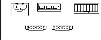
Main |
|
|
Dip |
|
Input |
|||
Power |
Switch |
Harness |
||||||
Connector |
|
Bank |
Connector |
|||||
8 |
7 |
6 |
5 |
4 |
3 |
2 |
On1 |
|
Siren #2 |
|
|
|
|
|
Siren #1 |
|
|
Connector |
|
|
|
Connector |
|
|||
Page 3
 Loading...