

Page 1
®
ENGINEERING COMPANY INC.
Route 145, Winthrop Road,
Chester, Connecticut 06412
Phone: (860) 526-9504
Fax: (860) 526-2009
Internet: www.whelen.com
Sales/Service e-mail: aviation@whelen.com
90101 Series Strobe Light Power Supply
Installation . . .
1. On both wings of the aircraft, remove the
wingtip access panel by unscrewing the
mounting screws.
2. Remove existing strobe light power supply
from the wing -t ip acc ess cut -out by re movi ng
the four mounting screws. Disconnect cables
from power supply.
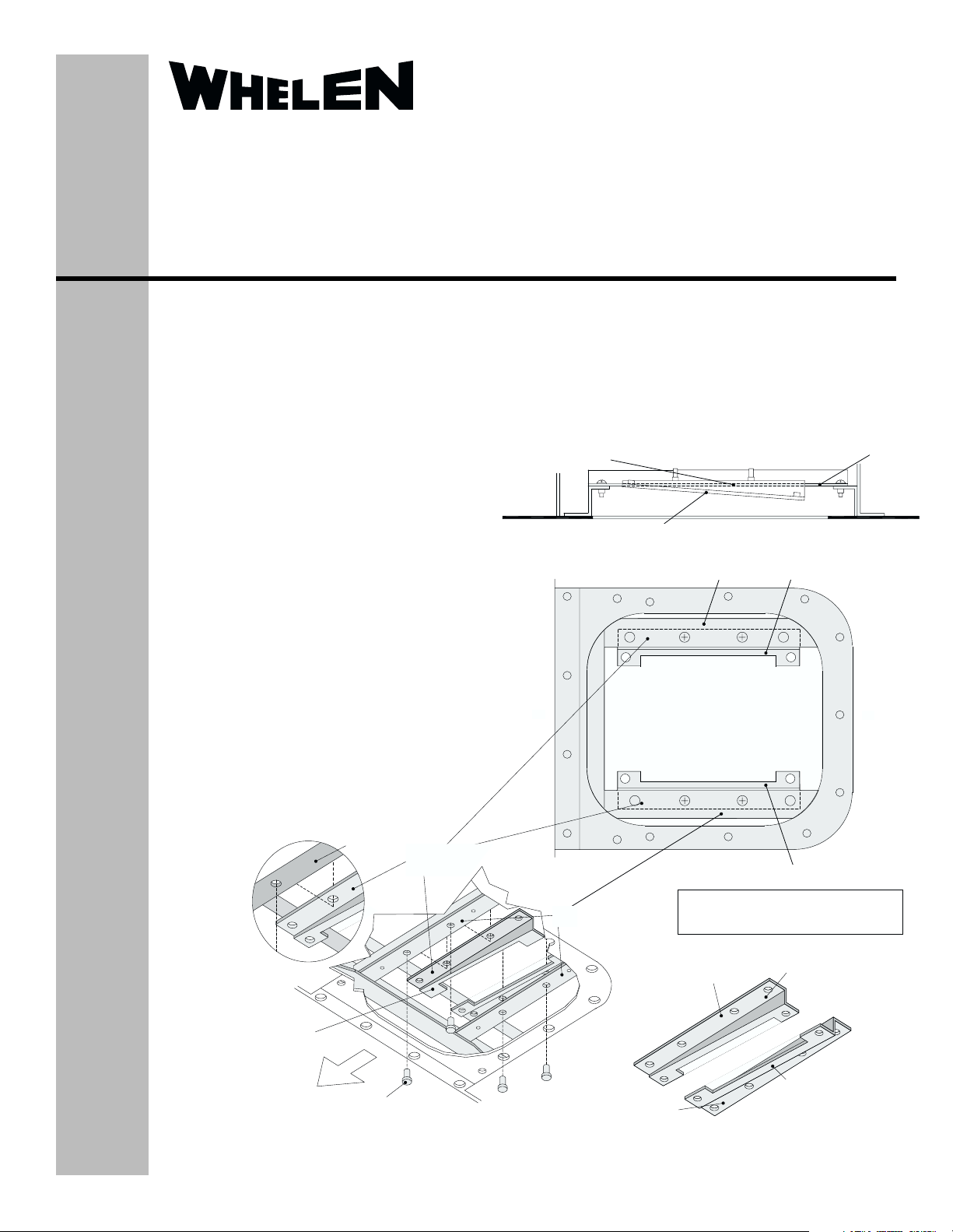
3. Install the two supplied mounting brackets
(“A” and “B”) with lips on top of existing
brackets, located inside wing-tip access cutout, and secure with the four mounting
screws.
IMPORTANT NOTE: When brackets are
installed, insure that the upward slope is
facing outboard of the wing.
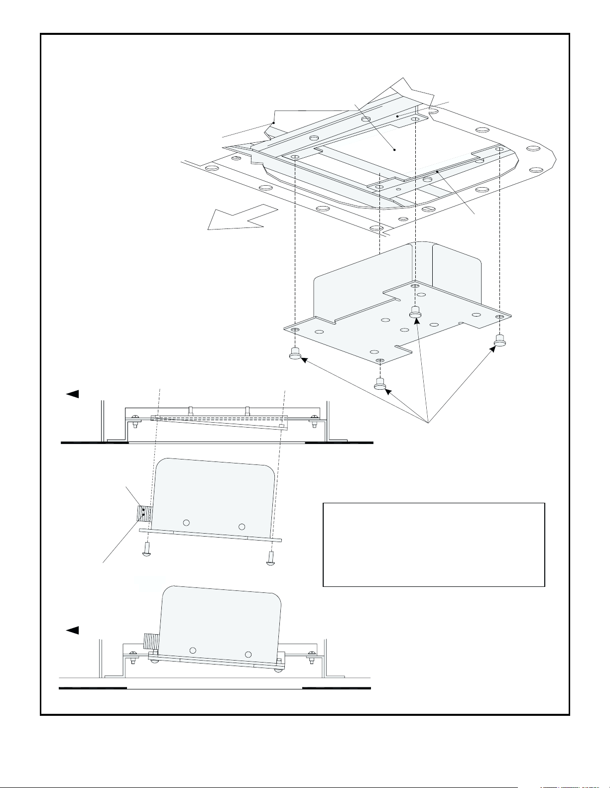
4. Connect the Whelen Strobe Light Power
Supply to the connectors of the existing
cables and install the power supply onto “A”
and “B” mounting brackets with the
connectors facing outboard. Secure the
power supply with the four #8-32 MS5195746mounting screws (supplied) to the “A” and
“B” mounting brackets.
5. Replace the wingtip access panel over the
wingtip cut-out, and secure w it h the m oun tin g
screws.
EXISTING
BRACKET
MOUNTING BRACKET
LIPS ON TOP OF EXISTING
BRACKETS
Wingtip Power Supply Replacement for
Cessna Citation 550, Ser ial #128 and above,
S550 and 560 serial #0001-0256 w ithout
SB560-3308 applied, with 90159 Series
Wingtip Strobe Light Assembly.
MOUNTING BRACKET LIPS
ON TOP OF EXISTING
BRACKETS
MOUNT. BRACKETS “A” & “B” TO SLOPE UPWARD FACING OUTBOARD OF AIRCRAFT WING
EXISTING BRACKET
OUTBOARD
MOUNTING BRACKET “B”
MOUNTING BRACKET “A”
EXISTING
BRACKET
VIEW A-A
INBOARD
MOUNTING BRACKETS “A”
AND “B” ARE TO SLOPE
UPWARD FACING OUTBOARD
OF AIRCRAFT WING
EXISTING MOUNTING SCREWS (QTY. 4) TO SECURE
Aviation
MOUNTING BRACKETS TO EXISTING BRACKETS
©1997 Whelen Engineering Company Inc.
Form No.13048C (052102)
EXISTING
BRACKET
D
AR
O
TB
U
O
BRACKET LIP
NOTE: ACCESS CUT-OUT SHOWN IN
ISOMETRIC DRAWINGS AS SEEN FROM
BELOW THE AIRCRAFT’S WING
MOUNTING BRACKET “B”
BRACKET LIP
PN / 11-170576-000
MOUNTING BRACKET “A”
PN / 11-170575-000
Page 1
Page 2
Strobe Light Power Supply Installation Instructions (Whelen 90101 Series)
AIRCRAFT
SKIN
UTBO
O
ARD
ACCESS
CUT-OUT
H
W
T
H
IG
L
MOUNTING
BRACKET “B”
MOUNTING
BRACKET “A”
E
B
O
Y
R
L
T
P
S
P
U
N
S
E
L
R
E
E
W
O
P
OUTBOARD
CONNECTORS ON STROBE
LIGHT POWER SUPPLY
MUST FACE OUTWARD
IMPORTANT NOTE: CONNECT
CABLES TO STROBE LIGHT
POWER SUPPLY BEFORE
INSERTING INSIDE ACCESS
CUT-OUT AND SECURE TO
MOUNTING BRACKETS.
OUTBOARD
WHELEN STROBE
LIGHT POWER SUPPLY
WHELEN STROBE
LIGHT POWER SUPPLY
Four, #8-32 (MS51957-46)
mounting screws to secure
strobe light power supply
to mounting brackets “A” & “B”
WARNING! THE STROBE LIGHT POWER SUPPLY
IS A HIGH VOLTAGE DEVICE. DO NOT REMOVE
STROBE TUBES OR DISMANTLE THE STROBE
LIGHT HEAD ASSEMBLIES WHILE IN OPERATION.
WAIT 10 MINUTES AFTER TURNING POWER
OFF
BEFORE STARTING WORK ON ANY TROUBLE
SHOOTING.
Form No.13048C
Page 2
Page 3

WHELEN 90159 SERIES WINGTIP
STROBE LIGHT ASSEMBLY
WARNING! THE STROBE LIGHT POWER SUPPLY IS A HIGH VOLTAGE
DEVICE DO NOT REMOVE STROBE TUBES OR DISMANTLE THE
WINGTIP SECTION
STROBE LIGHT HEAD ASSEMBLIES WHILE IN OPERATION.
OFF
WAIT 10 MINUTES AFTER TURNING POWER BEFORE STARTING
WORK ON ANY TROUBLE SHOOTING.
(MS51958-65)
BASE PLATE MOUNTING SCREWS (4)
#10-32 X ¾ INCH, PHILLIPS PAN HEAD
LENS GASKET
LENS
(MS51960-70)
PHILLIPS FLAT HEAD
LENS RETAINER MOUNTING
SCREWS (2), #10-32X1INCH,
NOTE: AT INSTALLATION,
MOUNTING SCREWS SHOULD BE
EVENLY
TIGHTENED TO A
MAXIMUM OF 13 IN./LBS. OF
LENS RETAINER
TORQUE.
IMPORTANT! SCREWS SHOULD
BE ALTERNATELY TIGHTENED
UNTIL THE FINAL TORQUE VALUE
HAS BEEN ACHIEVED.
TO POWER SUPPLY
Form No.13048C
(+ 28 VDC)
(-) GROUND
WHITE WIRE POSITIVE,
BLACK WIRE NEGATIVE,
BASE PLATE
Wingtip Anti-collision/
ASSEMBLY
Position Strobe Light Replacement
for Cessna 550 and 560 Series . . .
Page 3
the Whelen light assembly, using DME-20 or equivilant.
NOTE: CONNECTION METHOD TO BE CERTIFIED FAA TYPE.
1. Remove existing wingtip assembly.
2. Clean all excess adhesive from opening and mounting surface.
3. Fill lower hole, if any, with hardware included seperately.
4. Position doubler plate inside wing behind opening.
5. The position light wires should be fed through doubler plate.
6. Observe polarity of existing position light wires, and connect to the wires of
assembly to the doubler plate to align into position for step 9.
four base plate mounting screws.
7. Remove lens retainer, lens and gasket from base plate assembly.
8. Using the two lens retainer mounting screws, temporarily attach the base
9. Permanently align and attach base plate assembly to doubler plate using the
gasket, lens and lens retainer to base plate assembly, using the two lens
retainer screws. NOTE: Gasket should be aligned properly.
10. Remove the two lens retainer screws.
11. Following the proc edu re p r ov ide d f or th e m ou nti ng hard w are, se cu rely attach
13. Connect strobe power cable to strobe light power supply.
Page 4

DATE
11/17/92
11/2/92
DESCRIPTION
DELETED RIVETS
ADDED -02 & -03 UNITS
8386
8339
G
F
REV ECN
12/10/92
ADDED NOTES
8464
H
6/15/93
ADDED SHEET #4
9254
J
1/25/94
CHGD SPECS
10100
K
2/17/94
REV'D DWG & SPECS
10210
L
6/6/94
ROTATEMS CONNECTORS
10714
M
10/28/94
ADDED -05 ASSEMBLY
11300
N
2/2/95
ADDED -06 ASSEMBLY
11776
P
5/22/96
REVISEDRADIATED SUSCEPT. NOTE
14469
R
10/24/96
ADDED -07 ASSEMBLY
REV'DRADIATED SUSCEPT. NOTE
15283
T
3/4/97
REV'DRADIATED EMISSIONS NOTE
16256
U
7/8/97
ADDED-01 ASSEMBLY
17398
W
GENERAL NOTES:
(AVG)
JOULES......................16,6,6,6
FLASHRATE................45±5 BURSTS PER MIN.
INPUT CURRENT........4 AMPS or 2 AMPS
INPUT VOLTAGE.........14 VDC or 28 VDC (TYP)
1. SPECIFICATIONS:
WEIGHT......................1.7 lbs.
34 JOULES WITHIN 405ms.
ENERGY.....................22 JOULES WITHIN 200ms.
1.36 TYP.
PART NUMBERS 01-0790159-( ) MEETS THE MINIMUM REQUIREMENTS
STATED IN FAR PART 23 & PART 25 FOR ANTI-COLLISION LIGHT SYSTEMS.
2. THIS POWER SUPPLY (P/N 01-0790101-04) USED WITH STROBE LIGHT
TEMPERATURE/ALTITUDE - SECT. 4, CAT. D2
ENVIRONMENTAL TEST REQUIREMENTS IN ACCORDANCE WITH RTCA/DO-160C:
3. THE 01-0790101-04 POWER SUPPLY COMPLIES WITH THE FOLLOWING
VIBRATION - SECT. 8, ROBUST (8.6)
4
OFSHEET
25
2/18/94
REV
ROUTE145
CHESTER,CT 06412-0684
TELEPHONE(203) 526-9504
REL.DATE
POWER SUPPLY, STROBE LIGHT (HTS-CF-MS)
INPUT OUTPUT LABEL
01-0790101-04
10-0330445-00
1
1
ITEMQTY. DESCRIPTIONPARTNUMBER
R
PIONEERSIN SAFETY SIGNALS
DRAWINGWITHOUT WRITTEN AUTHORIZATION FROM WHELEN
COMPANYANY REPRODUCTION, DISCLOSURE OR USE OF THIS
THISDRAWING IS PROPRIETARY TO THE WHELEN ENGINEERING
WHELENENG. CO.
1994
C
ENGINEERINGCOMPANY
ENGINEERINGCOMPANY IS PROHIBITED.
UNLESSOTHERWISE SPECIFIED
TOLERANCE:
HTS - 90101 SERIES
1.7 lbs.
CALC.WT.
CONTRACTNO.
CUSTOMER
.XX = ±.03
ANGLES±1/2ANGLES °
90101 W
DWGNO.
NONE
POWER SUPPLY ASSY.
10402
SCALE
CAGECODE
2/21/94
2/18/94
10/28/94
10/28/94
DATE
DATE
DATE
DATE
JPA
VGC
VGC
GPS
APP.
ENG.
CH.
DR.
.XXX = ±.020
FINISH
MATERIAL
#
CAP PLUG
MFG. LABEL
POWER SUPPLY, HTS-CF-MS - MOD YAL14/28Q4516-1VA
22-0430469-00
01-0267530-00
10-0530592-02
2
41
13
2
POWER INPUT - SECT. 16, CAT B
SALT SPRAY - SECT. 14, CAT. S
SAND & DUST - SECT. 12, CAT. D
FLUIDS SUSCEPTABILITY - SECT. 11, SPRAY TEST (11.4.1)
WATERPROOFNESS - SECT. 10, CAT. S
VOLTAGE SPIKE - SECT. 17, CAT. B, PAR. 17.4
AUDIO FREQUENCY CONDUCTED SUSPECT. - SECT. 18, CAT. B, PAR. 18.3.1
MAGNETIC FIELDS INDUCED INTO EQ. - SECT. 19, CAT. B, PAR. 19.3.1
SPIKES INDUCED INTO INTERCONN. CABLES - SECT. 19, CAT. B, PAR 19.3.4
RADIATED AND CONDUCTED SUSCEPTABILITY - SECT. 20, CAT. U, PAR 20.4, 20.5
U
RADIATED AND CONDUCTED EMISSIONS - SECT. 21, CAT. B, PAR. 21.3, 21.4
R
4. FAA - STC, TSO - C96a APPROVED
5.60
.187 DIA.
(4) MOUNTING HOLES
5.100 MTG.
.25
321
5.00
TEST
AFTER FINAL
INSTALL CAP
.95
.25
3.625 MTG.
4.13
3.21
.080
CONN.(REF)
WIRING
C=SYNC.
B=GROUND(-)
A=POWER(+)
OR EQUIVALENT
MS3102R10SL-3P
INPUT
C=SYNC.
B=GROUND-
3.12
A=POWER
OUTPUT
A=ANODE
C=CATHODE
B=TRIGGER
Form No.13048C
Page 4
WIRING
OR EQUIVALENT
MS3102R10SL-3S CONN.(REF)
C=CATHODE
B=TRIGGER
A=ANODE
Page 5

1/19/9381/19/93
CHG 70603 TITLE
UPDATEDWG
ADD SHEET 2
ADD SHIELD GRD9213
REMOVE GASKET
CHG P/N OF IT 5
REV STROBE ASSY
REV'D SCREWS TO #6
9526
9149
9881
9019
8615
8902
B
A
REV ECN DESCRIPTION DATEREV ECN DESCRIPTION DATE
5/20/02
11/12/98
ADD "STC", DELETED "PMA"
ADDED TORQUESPEC TO LENS
RETAINERMTG SCREWS
20986
25628
U
V
10025
F
D
E
G
H
C
.62 R.
4/24/96
5/22/96
3/13/97
10/16/95
11/21/95
ROUTE 145
CHESTER, CT06412-0684
RIGHT LIGHTASSY. POS./ANTI-COLL. (PLASTIC LENS)01-0790159-02
01-0790159-05 LEFTLIGHT ASSY.POS./ANTI-COLL. (GLASS LENS)
*
*
R
LEFT LIGHTASSY. POS./ANTI-COLL. (PLASTIC LENS)
PART NUMBER DESCRIPTION
01-0790159-01
*
THISDRAWING IS PROPRIETARY TO THE WHELEN ENG.CO. INC., ANY
QUANTITY ITEM
REPRODUCTION,DISCLOSURE OR USE OF THIS DRAWING WITHOUT
TELEPHONE (860) 526-9504
ENGINEERING COMPANYINC.
MATERIAL
WRITTENAUTHORIZATION FROM WHELEN ENG. CO. INC. IS PROHIBITED
USEITEM 7 GASKET
ADDEDWEIGHTS
-05THRU -08
ADDEDFAA NOTE
CHANGEDP/N ITEM 5
ADDEDNEW ASSEMBLYS
CH.HDWARE, ADDED GASKET
DELETEDGASKET FOR GLASS LENS
REVISEDRADIATED SUSCEPT. NOTE
REV'DRADIATED SUSCEPT. NOTE
REV'DRADIATED EMISSIONS NOTE
ADDEDASSY'S -09 & -10
13401
M
13609
14305
N
P
REQUIRED IN WINGTIP
MIN. OPENING
14470
R
ADDEDITEM # 22
16349
T
NOTES:
1. SPECIFICATIONS:
POSITION LIGHT VOLTAGE......27.5V+/-0.5V
AVIATIONRED, GREEN, AND WHITE.
2. UNIT COMPLIES WITH COLOR REQUIREMENTS OF FARPART 25.1397(a).
POWER SUPPLYOF 22 JOULES MINIMUM, 30 JOULES MAXIMUM.
3. UNIT COMPLIES WITH FARPART 25.1401 REQUIREMENTS USING AN APPROVED
IN ACCORDANCE WITH RTCA/DO-160C:
4. UNIT COMPLIES WITH THE FOLLOWING ENVIRONMENTALTEST REQUIREMENTS
FLASHTUBE.............................XENON
VIBRATION:SECT. 8, ROBUST (8.6)
HUMIDITY: SECT.6, CATEGORY C
TEMPERATURE/ALTITUDE:SECT. 4, CATEGORYD2
LABEL, MFG.
RETAINER,LENS - POSITION LIGHT
LENS, GLASS
#10-32 X 1" PHILLIPS FHMS14-0050619-69
LENS, POSITION LIGHT - RED
1/8 x 1/2 FOAM PAD38-0125020-00
10-0530693-02
68-4230020-50
11-270587-001
68-4170665-30
68-4170665-34 LENS,GLASS EMI COATED
17
18
16
21--11
20
19
1
-
1
11
22
1
-
1111
--
11
-
111--1111111
22
1122
-1
1
1
-01 & -02 W/PLASTIC LENS - 1.3 lbs.
RADIATEDAND CONDUCTED EMISSIONS: SECTION 21, CATEGORY B, PAR. 21.3, 21.4
RADIATEDAND CONDUCTED SUSCEPTABILITY: SECTION 20, CATEGORYU, PAR. 20.4, 20.5
SPIKES INDUCED INTO INTERCONN. CABLES: SECT.19, CAT. B, PAR.19.3.4
VOLTAGESPIKE: SECT. 17, CATEGORYB, PAR. 17.4
WATERPROOFNESS:SECT. 10, CATEGORY S
FLUIDS SUSCEPTABILITY:SECT. 11, SPRAYTEST (11.4.1)
SALTSPRAY: SECT. 14, CATEGORYS
EXPLOSION: SECT.9, CATEGORY A
MAGNETIC FIELDS INDUCED INTO EQ.: SECTION 19, CAT.B, PAR. 19.3.1
POWER INPUT:SECTION 16, CATEGORY B
SAND AND DUST:SECTION 12, CATEGORY D
AUDIO FREQENCY CONDUCTED SUSCEPTABILITY:SECT. 18, CAT.B, PAR. 18.3.1
R
6. WEIGHTS: -05 & -06 W/GLASS LENS - 1.9 lbs.
5. FAA- STC, TSO-C30c AND TSO-C96a APPROVED.
T
11-- - - 22
GASKET,LENS - POSITION LIGHT
LAMP - W1290-28
LENS, POSITION LIGHT - GREEN
38-0230021-00
34A0428020-65
68-4230020-40
15
-
114
113
1
11
11
1-
RETAINER,PLASTIC LENS
LENS, PLASTIC
LABEL, MADE IN USA
LABEL, MFG.-01 & -02 ASSYS.
SCREW, 6-32 X 1/2 PPHMS (MS51957-30)
14-0050503-30
19-190154-001
68-4170581-3A
10-0320776-00
10-0530572-02
84716
112
1111019
11
11111
--
-
44111111441111
-
--
-
--
-
--
11
GASKET,LENS
STROBE ASSY- WINGTIP LIGHT
SCREW, 6-32 X 3/4 PPHSS (MS51957-32)
14-0050503-32
38-0270590-00
02-0270603-00
1
15441321
RETAINER,GLASS LENS
BASEPLATEASSY, WINGTIP LIGHT
#10-32 X 3/4" PPHMS
14-0050620-65
19-190187-001
06-170600-000
--
11
11
DOUBLER PLATE
01-0790159-10 RIGHTLIGHT ASSY.POS./ANTI-COLL. (EMI GLASS)
07-790157-001
1
1141141
11114411111144
*
RIGHT LIGHTASSY. POS./ANTI-COLL. (GLASS LENS)
LEFT LIGHTASSY. POS./ANTI-COLL. (EMI GLASS)
01-0790159-09
01-0790159-06
*
*
SEE SHEET 211057
13203
11312
J
L
K
12
11/1/94
RELEASEDATEDATESCALEDR.TOLERANCE: UNLESS OTHERWISE SPECIFIED
ISSUE SHEET OF
11/30/92
WINGTIP LIGHT
NONE
POSITION/ANTI-COLLISION
90159 V
DWGNO. REV
JAN
JAN
VGC
GPS
CH.
ENG.
APP.
10402
CAGECODEWHELENENG. CO. INC.
.XX=±.02
.XXX=±.002
1994
C
ANGLES ± 1/2°
FINISH
2/5/96CHANGEDMOUNTING HARDWARE
11/1/94
9/7/94
1/13/94
12/2/93
8/27/93
6/3/93
5/17/93
4/6/93
9.375
CLEARANCE HOLES FOR #10
8.12
3.45
.49
(2)PLACES
(2) PLACES
LENS RETAINER MOUNTING SCREW
2.38
A - ANODE
B - TRIGGER
3 PIN CONNECTOR
MS 3106F-10SL-3P
1.6
C - CATHODE
19.11 R.
7.65 R.
MOUNTING CONFIGURATION
.85 R.
2
10
22
20
NOTE:
MOUNTING SCREWS TO
BE TIGHTENED EVENLY
TO A MAXIMUM OF
13 IN./LBS. OF TORQUE.
IMPORTANT...
SCREWS SHOULD BE
ALTERNATELY TIGHTENED
UNTIL THE FINAL TORQUE
VALUE HAS BEEN
9765431
ACHIEVED.
19
8
1815
BY MOUNTING SCREW (ITEM 4)
SHIELD GROUND: TO BE SECURED
WHITE (POSITIVE)
BLACK (GROUND)
17
16
14
Form No.13048C
13
4
11.03
9.375
26"
APPROX.
1.89
22"
APPROX.
12
21
11
.62
3.06
3.50
(PLASTIC LENS)
3.65
REF.
WINGTIP SECTION
(GLASS LENS)
Page 5
Page 6

DATEREV ECN
12/2/93
8/27/93
DESCRIPTION
UPDATEDWG
ADDSHEET 2 (W\TAILIGHT)
9881
9526
G
F
REV ECN
DATE
5/20/02
11/12/98
DESCRIPTION
ADDEDTORQUE SPEC TO LENS
RETAINERMTG SCREWS
ADD"STC", DELETED "PMA"
25628
20986
V
U
9.375
3.45
1/13/94
ADDTAIL LIGHT SHIELD
10025
H
11/1/94
9/7/94
10/16/95
11/21/95
2/5/96
4/24/96
5/22/96
3/13/97
ADDEDWEIGHTS
ADDEDFAANOTE
ADDEDNEW ASSEMBLYS
CHANGEDP/N ITEM 3
-05THRU -08
CHANGEDMOUNTING HARDWARE
DELGASKET FOR GLASS LENS
USEITEM 10 GASKET
CHANGEDHARDWARE, ADDED GASKET
CHGTAIL LIGHT SHIELD
REVISEDRADIATED SUSCEPT. NOTE
REVISEDRADIATED SUSCEPT. NOTE
REVISEDRADIATED EMISSIONS NOTE30ADDEDITEM #30
ADDEDASSY'S -11 AND -12
11057
11312
13401
14302
13203
13609
14470
J
16349
K
M
P
L
N
R
T
#10-32 X 1" PHILLIPS FHMS
#10-32 X 3/4" PPHMS
GASKET,LENS
SCREW, 6-32 X 1/2 PPHSS (MS51957-30)
14-0050620-65
38-0270590-00
14-0050503-30
819110
44
11
11
441111
LAMPHOLDER ASSY,TAIL LIGHT (WINGTIP)
LAMP,ESG HALOGEN 28V
SCREW, 2-56 X 5/8 PPHM (MS51957-08)
14-0050531-08
34-0428070-64
11
11
11
11
11
11
11
11
BASEPLATEASSY, WINGTIP LIGHT
STROBE ASSY,WINGTIP LIGHT
NUT,2-56 SELF-LOCKING (MS21042-02)
13-0050517-02
06-170600-001
02-0270603-00
2
314451617
11
1
141
11441
141
141
141
DOUBLER PLATE
RIGHT LIGHTASSY. POS./ANTI-COLL/TAIL(EMI GLASS)
07-790177-001
01-0790159-12
1
1
1
1
1
1
*
LEFT LIGHTASSY. POS./ANTI-COLL/TAIL(EMI GLASS)
01-0790159-11
*
NOTES:
FLASHTUBE.............................XENON
POSITION LIGHT VOLTAGE......27.5V0.5V
1. SPECIFICATIONS:
.62 R.
AVIATIONRED, GREEN, AND WHITE.
2. UNIT COMPLIES WITH COLOR REQUIREMENTS OF FARPART 25.1397(a).
POWER SUPPLYOF 22 JOULES MINIMUM, 30 JOULES MAXIMUM.
3. UNIT COMPLIES WITH FARPART 25.1401 REQUIREMENTS USING AN APPROVED
VIBRATION:SECT. 8, ROBUST (8.6)
HUMIDITY: SECT.6, CATEGORY C
TEMPERATURE/ALTITUDE: SECT. 4, CATEGORYD2
IN ACCORDANCE WITH RTCA/DO-160C:
4. UNIT COMPLIES WITH THE FOLLOWING ENVIRONMENTALTEST REQUIREMENTS
RETAINER, PLASTIC LENS
LENS, PLASTIC
LABEL, MADE IN USA
LENS, POSITION LIGHT - RED
RETAINER, LENS - POSITION LIGHT
LENS, POSITION LIGHT - GREEN
LAMP - W1290-28
GASKET,LENS - POSITION LIGHT
68-4230020-50
68-4230020-40
34A0428020-65
38-0230021-00
16
17
18
19
1
1
1
-
11111
-
1111-
-
-
-
-
1111-
LABEL, MFG.
19-190154-0011102-0250546-00
68-4170581-3A
10-0320776-00
14-0050619-69
10-0530692-02
15
11112113
14
22
11114
-
-
--
22
-1111
-1111
-
--
-
1/8 x 1/2 FOAM PAD
FLATWASHER,#4 BRASS
SCREW, 6-32 X 3/4 PPHSS (MS51957-32)
SHIELD, TAILLIGHT - WINGTIP
GROMMET
SCREW, 6-32 X 5/16 PPHSS
RETAINER, GLASS LENS
LENS, GLASS
LABEL, MFG.
LENS, GLASS EMI COATED
11-270587-001
16-0400910-03
14-0050503-32
21-11091202-0
14-0050503-27
23
25
24
22
11
11
11
11
38-0125020-00
222120
1
1
11
11
12211
1
11
1
11
12211
70-0350567-00
19-190187-001
68-4170665-30
10-0530694-02
68-4170665-34
26
28
27
11
--
-03 & -04 W/PLASTIC LENS - 1.4 lbs.
--
--2911
EXPLOSION: SECT.9, CATEGORY A
MAGNETIC FIELDS INDUCED INTO EQ.: SECTION 19, CAT. B, PAR.19.3.1
POWER INPUT:SECTION 16, CATEGORY B
SAND AND DUST:SECTION 12, CATEGORY D
SPIKES INDUCED INTO INTERCONN. CABLES: SECT.19, CAT. B, PAR.19.3.4
AUDIO FREQENCY CONDUCTED SUSCEPTABILITY:SECT. 18, CAT.B, PAR. 18.3.1
R
5. FAA- STC, TSO-C30c AND TSO-C96a APPROVED.
T
RADIATEDAND CONDUCTED EMISSIONS: SECTION 21, CATEGORY B, PAR. 21.3, 21.4
RADIATEDAND CONDUCTED SUSCEPTABILITY: SECTION 20, CATEGORYU, PAR. 20.4, 20.5
VOLTAGESPIKE: SECT. 17, CATEGORYB, PAR. 17.4
WATERPROOFNESS:SECT. 10, CATEGORYS
FLUIDS SUSCEPTABILITY:SECT. 11, SPRAYTEST (11.4.1)
SALTSPRAY: SECT. 14,CATEGORY S
11
11
11----30
11
11
11
111122
--
6. WEIGHTS: -07 & -08 W/GLASS LENS - 2.0 lbs.
28
12
8.12
19.11 R.
8
7
24
26
7.65 R.
NOTE:
PLACE BETWEEN LAMPHOLDER
AND MOUNTING SURFACE
23
6
.49
2.38
.85 R.
MIN. OPENING
REQUIRED IN WINGTIP
MOUNTING CONFIGURATION
9
27
11
10
LEFT LIGHTASSY. POS./ANTI-COLL/TAIL(GLASS LENS)
RIGHT LIGHTASSY. POS./ANTI-COLL/TAIL(GLASS LENS)
RIGHT LIGHTASSY. POS./ANTI-COLL/TAIL(PLASTIC LENS)
01-0790159-04
01-0790159-08
01-0790159-07
*
*
*
13
ROUTE 145
LEFT LIGHTASSY. POS./ANTI-COLL/TAIL(PLASTIC LENS)
PART NUMBER DESCRIPTION
01-0790159-03
*
THISDRAWING IS PROPRIETARY TO THE WHELEN ENG.CO. INC., ANY
QUANTITY ITEM
NOTE:
MOUNTING SCREWS TO
BE TIGHTENED EVENLY
CHESTER, CT06412-0684
R
REPRODUCTION,DISCLOSURE OR USE OF THIS DRAWING WITHOUT
TO A MAXIMUM OF
TELEPHONE (860) 526-9504
ENGINEERINGCOMPANY INC.
MATERIAL
WRITTENAUTHORIZATION FROM WHELEN ENG. CO. INC. IS PROHIBITED
13 IN./LBS. OF TORQUE.
22
11/1/94
RELEASEDATEDATESCALEDR.TOLERANCE: UNLESS OTHERWISE SPECIFIED
ISSUE SHEET OF
7/29/93
WINGTIP LIGHT
NONE
90159 V
POSITION/ANTI-COLLISION
DWGNO. REV
VGC
GPS
JNELSON
JNELSON
CH.
ENG.
APP.
10402
CAGECODE
.XX=±.02
.XXX=±.002
WHELENENG. CO. INC.
1993
C
ANGLES ± 1/2°
FINISH
IMPORTANT...
SCREWS SHOULD BE
ALTERNATELY TIGHTENED
UNTIL THE FINAL TORQUE
VALUE HAS BEEN
ACHIEVED.
22
CLEARANCE HOLES FOR #10
(2)PLACES
(2) PLACES
LENS RETAINER MOUNTING SCREW
MS 3106F-10SL-3P
3 PIN CONNECTOR
1.6
11.03
9.375
A -ANODE
.62
C - CATHODE
B - TRIGGER
9
BLACK (GROUND)
WHITE (POSITIVE)
SHIELD GROUND: TO BE SECURED
BY MOUNTING SCREW (ITEM 8)
345
2
201716
19
18 21
25
1
22"
APPROX.
26"
APPROX.
1.89
3.06
3.50
(PLASTIC LENS)
22"
APPROX.
REF.
WINGTIP SECTION
8
15
29
14
Form No.13048C
3.65
(GLASS LENS)
Page 6
 Loading...