

Page 1

®
ENGINEERING COMPANY INC.
51 Winthrop Road
Chester, Connecticut 06412-0684
500 Series Halogen Lighthead
Installation Guide:
Phone: (860) 526-9504
Fax: (860) 526-4078
Internet: www.whelen.com
Sales e-mail: autosale@whelen.com
Canadian Sales e-mail: autocan@whelen.com
Customer Service e-mail: custserv@whelen.com
Safety First
This document provides all the necessary information to allow your Whelen product to be properly and safely installed.
Before beginning the installation and/or operation of your new product, the installation technician and operator must
read this manual completely. Important information is contained herein that could prevent serious injury or damage.
• Proper installation of this product requires the installer to have a good understanding of automotive electronics,
systems and procedures.
• If mounting this product requires drilling holes, the installer MUST be sure that no vehicle components or other
vital parts could be damaged by the drilling process. Check both sides of the mounting surface before drilling
begins. Also de-burr any holes and remove any metal shards or remnants. Install grommets into all wire
passage holes.
• If this manual states that this product may be mounted with suction cups, magnets, tape or Velcro®, clean the
mounting surface with a 50/50 mix of isopropyl alcohol and water and dry thoroughly.
• Do not install this product or route any wires in the deployment area of your air bag. Equipment mounted or
located in the air bag deployment area will damage or reduce the effectiveness of the air bag, or become a
projectile that could cause serious personal injury or death. Refer to your vehicle owner’s manual for the air bag
deployment area. The User/Installer assumes full responsibility to determine proper mounting location, based
on providing ultimate safety to all passengers inside the vehicle.
• For this product to operate at optimum efficiency, a good electrical connection to chassis ground must be
made. The recommended procedure requires the product ground wire to be connected directly to the NEGATIVE
(-) battery post.
• If this product uses a remote device to activate or control this product, make sure that this control is located in
an area that allows both the vehicle and the control to be operated safely in any driving condition.
• Do not attempt to activate or control this device in a hazardous driving situation.
• This product contains either strobe light(s), halogen light(s), high-intensity LEDs or a combination of these
lights. Do not stare directly into these lights. Momentary blindness and/or eye damage could result.
• Use only soap and water to clean the outer lens. Use of other chemicals could result in premature lens cracking
(crazing) and discoloration. Lenses in this condition have significantly reduced effectiveness and should be
replaced immediately. Inspect and operate this product regularly to confirm its proper operation and mounting
condition. Do not use a pressure washer to clean this product.
• It is recommended that these instructions be stored in a safe place and referred to when performing
maintenance and/or reinstallation of this product.
• FAILURE TO FOLLOW THESE SAFETY PRECAUTIONS AND INSTRUCTIONS COULD RESULT IN DAMAGE TO
THE PRODUCT OR VEHICLE AND/OR SERIOUS INJURY TO YOU AND YOUR PASSENGERS!
Automotive: Lightheads
For warranty information regarding this product, visit www.whelen.com/warranty
©2001 Whelen Engineering Company Inc.
Form No.13572D (042208)
Page 1
Page 2
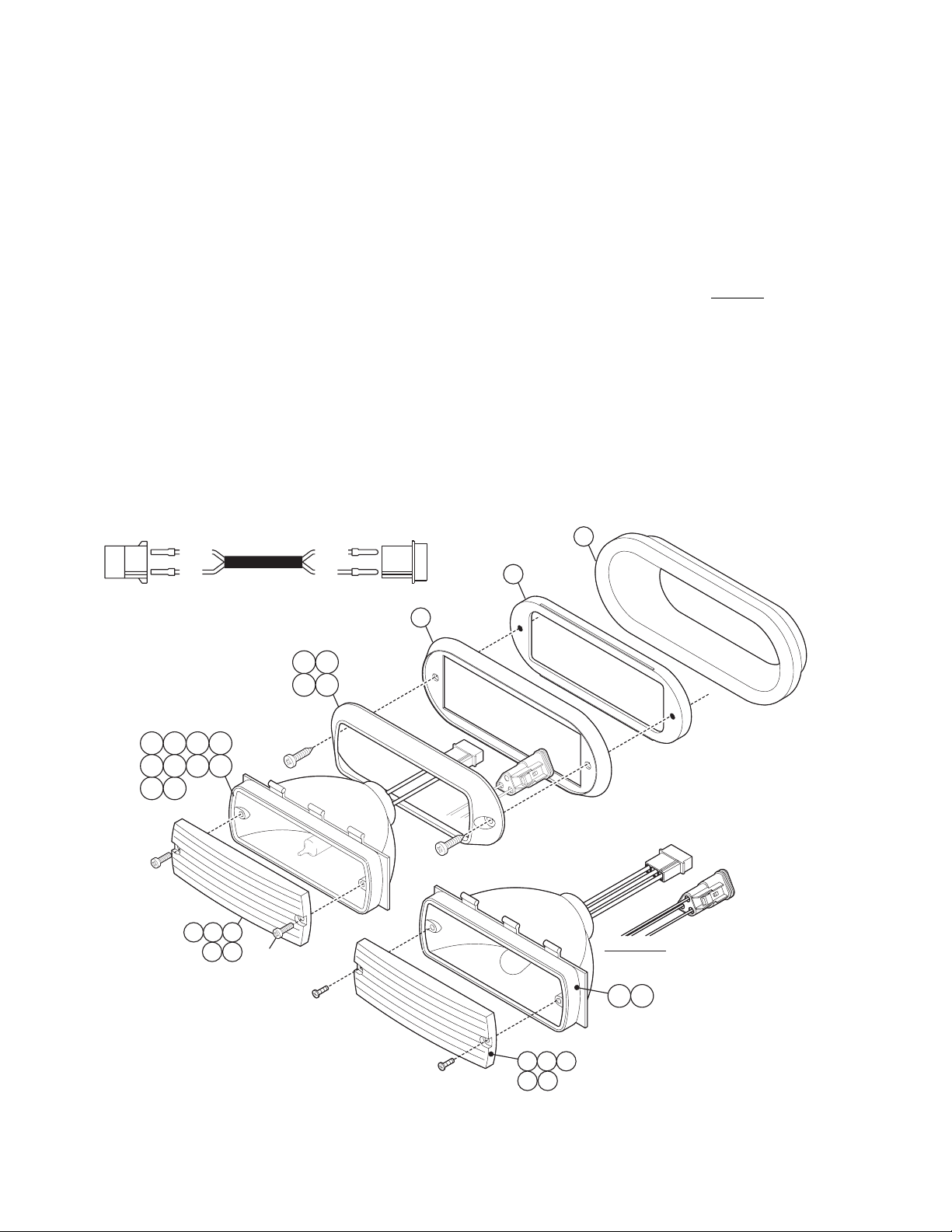
Installation:
1. Position the lighthead in its approximate mounting location and make sure that the lighthead will not interfere with any
existing equipment. Also be aware of any items on the opposite side of the mounting surface to prevent any possible
damage to existing components.
2. Using the measurements supplied, mark off the mounting holes and lighthead cut-out hole onto the mounting surface.
3. Drill the 2 screw holes and cut the mounting hole out as indicated.
4. Wire the lighthead as shown below and secure it to the mounting location using the supplied sheet metal screws.
Note: All customer supplied wires that connect to the positive terminal of the battery must be
sized to supply at least 125% of the maximum operating current and FUSED
to carry that load. DO NOT USE CIRCUIT BREAKERS WITH THIS PRODUCT!
Caution: The replacement of any halogen bulb requires the use of safety glasses to prevent injury.
Do not handle the bulb with bare hands. Use gloves to prevent possible injuries.
IMPORTANT! Before returning this vehicle to active service, visually confirm the proper operation of this product,
as well as all vehicle components/equipment.
at the battery
LIGHT
HEAD
NOTE: This cable is shown for reference only and is not included.
RED WIRE- POSITION #1 / WHITE WIRE- POSITION #3
WHITEWHITE
RED
RED
19 20
23 24
2 3 4 5
6 7 8 9
10 11
14 15 16
17 18
#6 X 1/2 PPH THREAD
FORMING SCREW
25
#10 X 3/4
PPHSMS
POWER
SUPPLY
21
22
3-wire Note:
RED.......
Tail
BLACK..
Brake
WHITE...
Ground
12 13
Page 2
161514
1817
Page 3
QTY. QTY.
HOLE
for #10
SCREW
HOLE
for #10
SCREW
MOUNTING SURFACE
MOUNTING SURFACE
1
A/R
A/R
A/R
A/R
A/R
A/R
A/R
A/R
A/R
MOUNTING KITS
QTY. QTY. ITEM PART NUMBER DESCRIPTION
QTY.QTY.
22222222 12222
1
1
1
A/R
A/R
A/R
A/R
A/R
A/RA/R
A/R
A/R
A/R
QTY.QTY.
-1
1-
11
11
22
A/R
A/R
A/R
A/R
A/R A/R
ITEM
-
-
19
20
21
22
-
QTY.QTY.QTY.
1
1
1
A/R
A/R
A/R
A/R
A/R
A/R
A/R
A/R
PART NUMBER
01-0463308-01
01-0463308-00
11-763226-000
11-763226-001
07-563241-000
21-0064188-00
A/R
A/RA/R
A/R
A/R
A/R
QTY.QTY.QTY.
1 2
1
1
1
1
A/R
A/R
A/R
A/R
A/R
A/R
A/RA/R
A/R
A/R
A/R
A/R
A/R
A/RA/R
A/R
A/R
A/R
A/R
A/R
A/R
GROMMET MOUNT KIT / MODEL 500 SERIES / CHROME
GROMMET MOUNT KIT / MODEL 500 SERIES / BLACK
FLANGE / MODEL 500 SERIES / BLACK
FLANGE / MODEL 500 SERIES / CHROME
ADAPTER / D.O.T. / MODEL 500 SERIES
GROMMET
SCREW / #10 X 3/4" PPHSMS
01-06835770_0
01-06835770_2
01-06835771_0
01-06835771_2
01-06835771_3
01-06835771_4
01-06835771_5
01-06835772_2
01-06835772_3
01-06835772_4
01-06835773_B
01-06835774_B
15-065419-080
02-0383577-00
02-0383577-02
3
02-0383577-10
4
5
02-0383577-12
02-0383577-13
6
02-0383577-14
7
02-0383577-15
8
02-0383577-22
9
02-0383577-23
10
02-0383577-24
11
02-0383577-3B
12
13
02-0383577-4B
68-1963237-10
14
68-1963237-20
15
68-1963237-30
16
68-1963237-40
17
68-1963237-50
18
DESCRIPTION
ASSEMBLY / 52 HALOGEN 2 WIRE 3 POS AMP 12V-35H
ASSEMBLY / 52 HALOGEN 2 WIRE 3 POS AMP 28V-35W
ASSEMBLY / 52 HALOGEN 2 WIRE DEUTSCH 12V-35H
ASSEMBLY / 52 HALOGEN 2 WIRE DEUTSCH 28V-35W
ASSEMBLY / 52 HALOGEN 2 WIRE DEUTSCH 12V-27H
ASSEMBLY / 52 HALOGEN 2 WIRE DEUTSCH 12V-20W
ASSEMBLY / 52 HALOGEN 2 WIRE DEUTSCH 14V-35W
ASSEMBLY / 52 HALOGEN 2 WIRE 2 POS AMP 28V-35W
ASSEMBLY / 52 HALOGEN 2 WIRE 2 POS AMP 12V-27H
ASSEMBLY / 52 HALOGEN 2 WIRE 2 POS AMP 12V-20W
ASSEMBLY / 52 HALOGEN 3 WIRE 3 POS AMP 12.8V-14V 27/12W
ASSEMBLY / 52 HALOGEN 3 WIRE DEUTSCH 12.8V-14V 27/12W
SCREW / #6 X 1/2" PPH THREAD FORMING
SUB-ASSEMBLY / 52 HALOGEN 2 WIRE 3 POS AMP 12V-35H
SUB-ASSEMBLY / 52 HALOGEN 2 WIRE 3 POS AMP 28V-35W
SUB-ASSEMBLY / 52 HALOGEN 2 WIRE DEUTSCH 12V-35H
SUB-ASSEMBLY / 52 HALOGEN 2 WIRE DEUTSCH 28V-35W
SUB-ASSEMBLY / 52 HALOGEN 2 WIRE DEUTSCH 12V-27H
SUB-ASSEMBLY / 52 HALOGEN 2 WIRE DEUTSCH 12V-20W
SUB-ASSEMBLY / 52 HALOGEN 2 WIRE DEUTSCH 14V-35W
SUB-ASSEMBLY / 52 HALOGEN 2 WIRE 2 POS AMP 28V-35W
SUB-ASSEMBLY / 52 HALOGEN 2 WIRE 2 POS AMP 12V-27H
SUB-ASSEMBLY / 52 HALOGEN 2 WIRE 2 POS AMP 12V-20W
SUB-ASSEMBLY / 52 HALOGEN 3 WIRE 3 POS AMP 12.8V-14V 27/12W
SUB-ASSEMBLY / 52 HALOGEN 3 WIRE DEUTSCH 12.8V-14V 27/12W
LENS MODEL 52 - AMBER/
LENS MODEL 52 - BLUE/
LENS MODEL 52 - CLEAR/
LENS MODEL 52 - GREEN/
LENS / MODEL 52 - RED
QTY.QTY.
-1
1-
11
22
PART NUMBER
ITEM
01-0463297-01
-
01-0463297-00
-
11-763226-000
23
11-763226-001
24
38-0461299-00
25
-
FLANGE MOUNT KIT / MODEL 500 SERIES / CHROME
FLANGE MOUNT KIT / MODEL 500 SERIES / BLACK
FLANGE / MODEL SERIES / BLACK500
FLANGE / MODEL SERIES / CHROME500
GASKET
SCREW / #10 X 3/4" PPHSMS
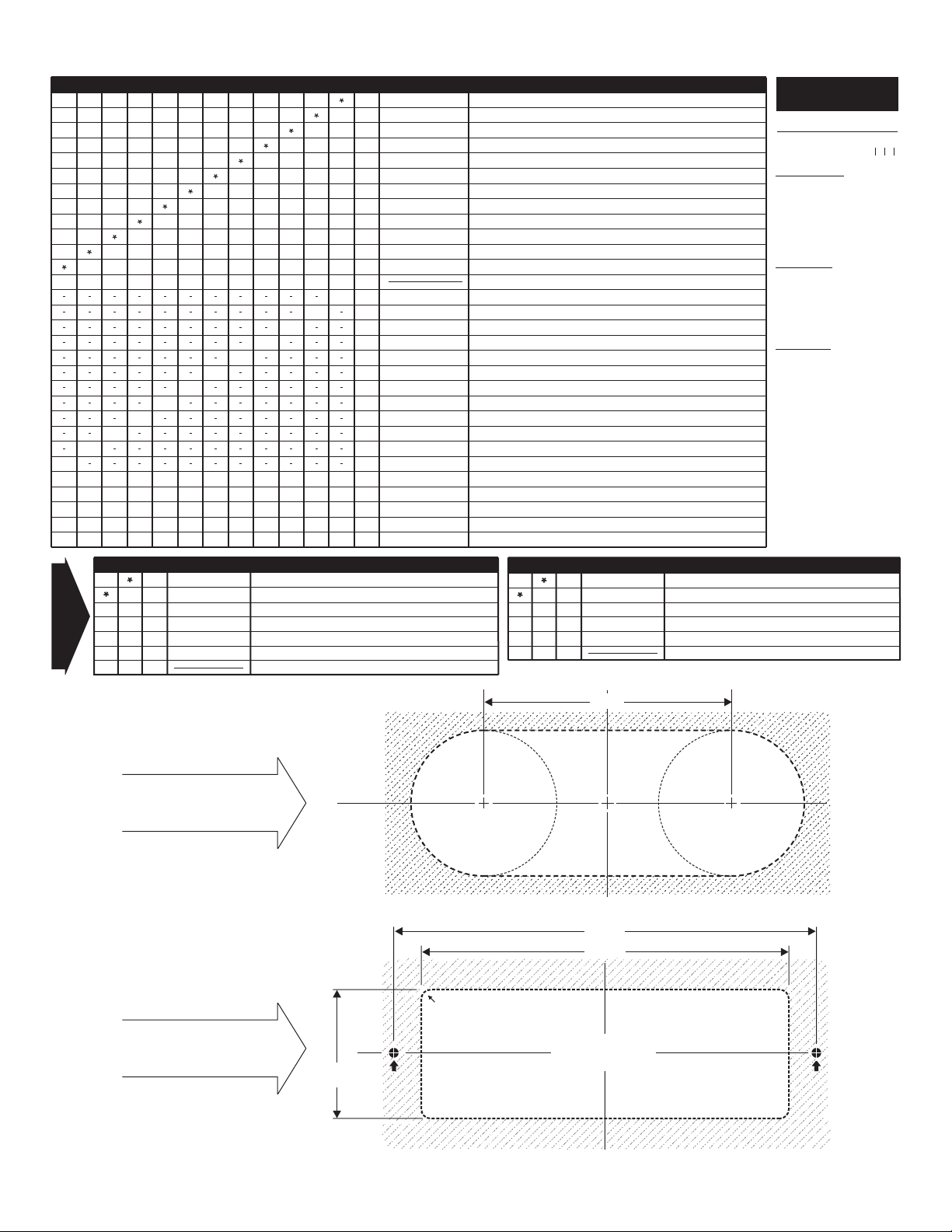
ORDERING
INFORMATION:
EXAMPLE OF PART NUMBER
01-0683577-___
BULB WATTAGE
0=12V-35H
2=
28V-35W
3=
12V-27H
4=
12V-20W
5=
14V-35W
B=
12.8V/14V-27/12 WATT
LENS COLOR
A=AMBER
B=
BLUE
C=
CLEAR
G=
GREEN
R=
RED
CONNECTOR
0=2 WIRE 3 POS AMP
1=
2 WIRE 3 POS DEUTSCH
3=
3 WIRE 3 POS AMP
4=
3 WIRE 3 POS DEUTSCH
IMPORTANT: When
replacing a halogen
bulb, always be sure
to replace it with one
of the exact same
specifications.
DESCRIPTION
CONNECTOR
LENS COLOR
BULB WATTAGE
MOUNTING
CONFIGURATION for
GROMMET MOUNT
MOUNTING
CONFIGURATION for
FLANGE MOUNT
1.74
C
LCL
HOLE
HOLE
for #10
for #10
SCREW
SCREW
1.25 RADIUS
CORNER RADII .125
(Optional)
Page 3
4.25
C
L
5.750
5.20
MOUNTING HOLE
(CUT-OUT)
1.25 RADIUS
MOUNTING SURFACE
MOUNTING SURFACE
MOUNTING SURFACE
MOUNTING SURFACE
HOLE
HOLE
for #10
for #10
SCREW
SCREW
 Loading...