

Page 1

®
ENGINEERING COMPANY INC.
51 Winthrop Road
Chester, Connecticut 06412-0684
Installation Guide:
4500 Series Lightbar
Phone: (860) 526-9504
Fax: (860) 526-4078
Internet: www.whelen.com
Sales e-mail: autosale@whelen.com
Canadian Sales e-mail: canadiansales@whelen.com
Customer Service e-mail: custserv@whelen.com
Safety First
This document provides all the necessary information to allow your Whelen product to be properly and safely installed.
Before beginning the installation and/or operation of your new product, the installation technician and operator must
read this manual completely. Important information is contained herein that could prevent serious injury or damage.
• Proper installation of this product requires the installer to have a good understanding of automotive electronics,
systems and procedures.
• Whelen Engineering recommends the use of waterproof butt splices and/or connectors if that connector could be
exposed to moisture.
• Failure to use specified installation parts and/or hardware will void the product warranty!
• If mounting this product requires drilling holes, the installer MUST be sure that no vehicle components or other
vital parts could be damaged by the drilling process. Check both sides of the mounting surface before drilling
begins. Also de-burr any holes and remove any metal shards or remnants. Install grommets into all wire passage
holes.
• If this manual states that this product may be mounted with suction cups, magnets, tape or Velcro®, clean the
mounting surface with a 50/50 mix of isopropyl alcohol and water and dry thoroughly.
• Do not install this product or route any wires in the deployment area of your air bag. Equipment mounted or
located in the air bag deployment area will damage or reduce the effectiveness of the air bag, or become a
projectile that could cause serious personal injury or death. Refer to your vehicle owner’s manual for the air bag
deployment area. The User/Installer assumes full responsibility to determine proper mounting location, based on
providing ultimate safety to all passengers inside the vehicle.
• For this product to operate at optimum efficiency, a good electrical connection to chassis ground must be made.
The recommended procedure requires the product ground wire to be connected directly to the NEGATIVE (-)
battery post.
• If this product uses a remote device to activate or control this product, make sure that this control is located in an
area that allows both the vehicle and the control to be operated safely in any driving condition.
• Do not attempt to activate or control this device in a hazardous driving situation.
• This product contains either strobe light(s), halogen light(s), high-intensity LEDs or a combination of these lights.
Do not stare directly into these lights. Momentary blindness and/or eye damage could result.
• Use only soap and water to clean the outer lens. Use of other chemicals could result in premature lens cracking
(crazing) and discoloration. Lenses in this condition have significantly reduced effectiveness and should be
replaced immediately. Inspect and operate this product regularly to confirm its proper operation and mounting
condition. Do not use a pressure washer to clean this product.
• It is recommended that these instructions be stored in a safe place and referred to when performing maintenance
and/or reinstallation of this product.
• FAILURE TO FOLLOW THESE SAFETY PRECAUTIONS AND INSTRUCTIONS COULD RESULT IN DAMAGE TO THE
PRODUCT OR VEHICLE AND/OR SERIOUS INJURY TO YOU AND YOUR PASSENGERS!
Automotive: Lightbars
For warranty information regarding this product, visit www.whelen.com/warranty
©2002 Whelen Engineering Company Inc.
Form No.13738G (040913)
Page 1
Page 2
Lighthead mounting holes, fit onto raised bosses on mounting bracket.
LED LIGHTHEAD
STROBE
LIGHTHEAD
Clips on bracket snap
over edge of lighthead.
Fig. 4
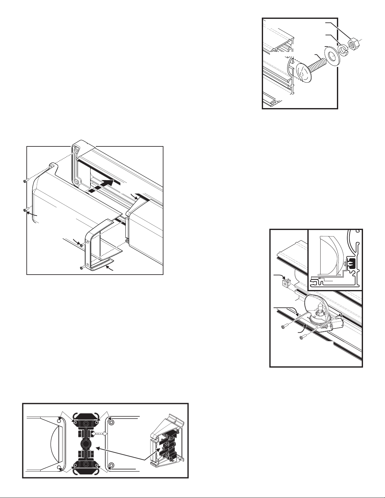
Rotator base
sits on tape
Rotator base
sits
on tape
Rotator Removal and Installation
Rotator base
sits on tape
Tape
Fastex
Grommet
Side View
TAPE
Fig. 3
Screws thread into fastex grommet
that is inserted into base.
IMPORTANT! The lightbar should be located a minimum of 16" from any radio antennas!
Removal and
Installation of Lens
and Lenscap
Fig. 2
Remove screws
from end of lenscap
Remove screws and lens
retainer, then remove
lens or lenscap
LENS RETAINER
MOUNTING
BRACKET
Fig. 1
Mounting the Lightbar
to the vehicle
3/8" X 16 HEX NUT
3/8" LOCKWASHER
3/8" FLATWASHER
3/8 -16 X 1-1/4 STEP BOLT
Installation:
Note: When routing wires, it is important to choose a path that will keep them away from
excessive heat or any vehicle equipment that could compromise the wires integrity.
1. This lightbar mounts with 1-1/4” bolts extending from the rear of the housing. Position the unit in its exact
mounting location and use an awl or other suitable tool to scribe the areas to be drilled (Fig. 1).
2. Remove the lightbar. Using a drill bit sized for a 3/8” step bolt, drill a hole in each of the areas scribed in
step 1. Return the lightbar to its mounting location and secure it to the vehicle with supplied hardware.
Wiring:
WARNING: All Customer supplied wires that connect to the positive terminal of the battery must be
sized to supply at least 125% of the maximum operating current and FUSED at the battery to carry
that load. DO NOT USE CIRCUIT BREAKERS WITH THIS PRODUCT!
IMPORTANT! All Positive input wires must be individually fused. Due to the large number of possible configurations, each with their own
fusing requirements, it is the installation technician's responsibility to determine the maximum current draw for each input wire and fuse that
wire at 125% of that value.
Servicing your lightbar:
NOTE: Before opening your lightbar for service or repair always be sure to
Disconnect the lightbar from it’s power source. (See strobe light warning below.)
Lens or Lenscap: Removal or Installation
1.To remove a lenscap, remove the 2 screws from the end of the lenscap, and the 2
screws from the opposite side that thread through the lens retainer into the lighthead
mounting bracket. Pull the lenscap off (Fig. 2).
2.To remove a lens, remove the 4 phillips head screws that thread through the lens
retainer into the lighthead mounting bracket and then pull the lens off.
lightbar’s harness by unplugging the Amp 2 position pin connector. NOTE: It is easier to remove the
existing rotator from the extrusion if the reflector is facing the front of the lightbar (Fig. 3).
4. Loosen the two screws that secure the rotator base to the extrusion (2 or 3 turns) and lift the rear of the
rotator base then remove the rotator from the extrusion.
Installation of a New Rotator:
1. Remove any adhesive tape on the lightbar base left from the old rotator.
2. Remove the backing from the piece of 2-sided tape and apply it to the lightbar base in the same location
as the previous tape (Fig. 3).
3. Plug the new rotator into the old rotator’s harness plug.
4. Place the new rotator inside the extrusion in the same area the old rotator was removed from but don’t
tighten the screws yet.
5. Remove the backing from the tape and press the rotator base down onto the lightbar base firmly, being careful not pinch any wires between the base
and extrusion, then tighten the mounting screws.
6. Reconnect lightbar to power and test for proper operation then return any lenscaps or lenses you had to remove.
Removing an Existing Rotator:
1. Disconnect the lightbar from power.
WAR NIN G: For lightbars with
strobe lights, wait a minimum of 10
minutes before proceeding.
2. Remove the lens or lenscap in front of
the rotator you wish to replace.
3. Disconnect the rotator from the
Servicing Lightheads: Strobe, Halogen or LED
WARNING: The strobe light power supply is a high voltage device. Do
not touch or remove the strobe tube assembly while in operation. Wait 10
minutes after disconnecting the unit from its power source before
starting any work or trouble shooting.
Removal and Installation
1. Disconnect the lightbar from it’s power source.
2. To remove the lighthead, first remove the lens or lenscap necessary to
access the lighthead you wish to service or replace.
Page 2
Page 3
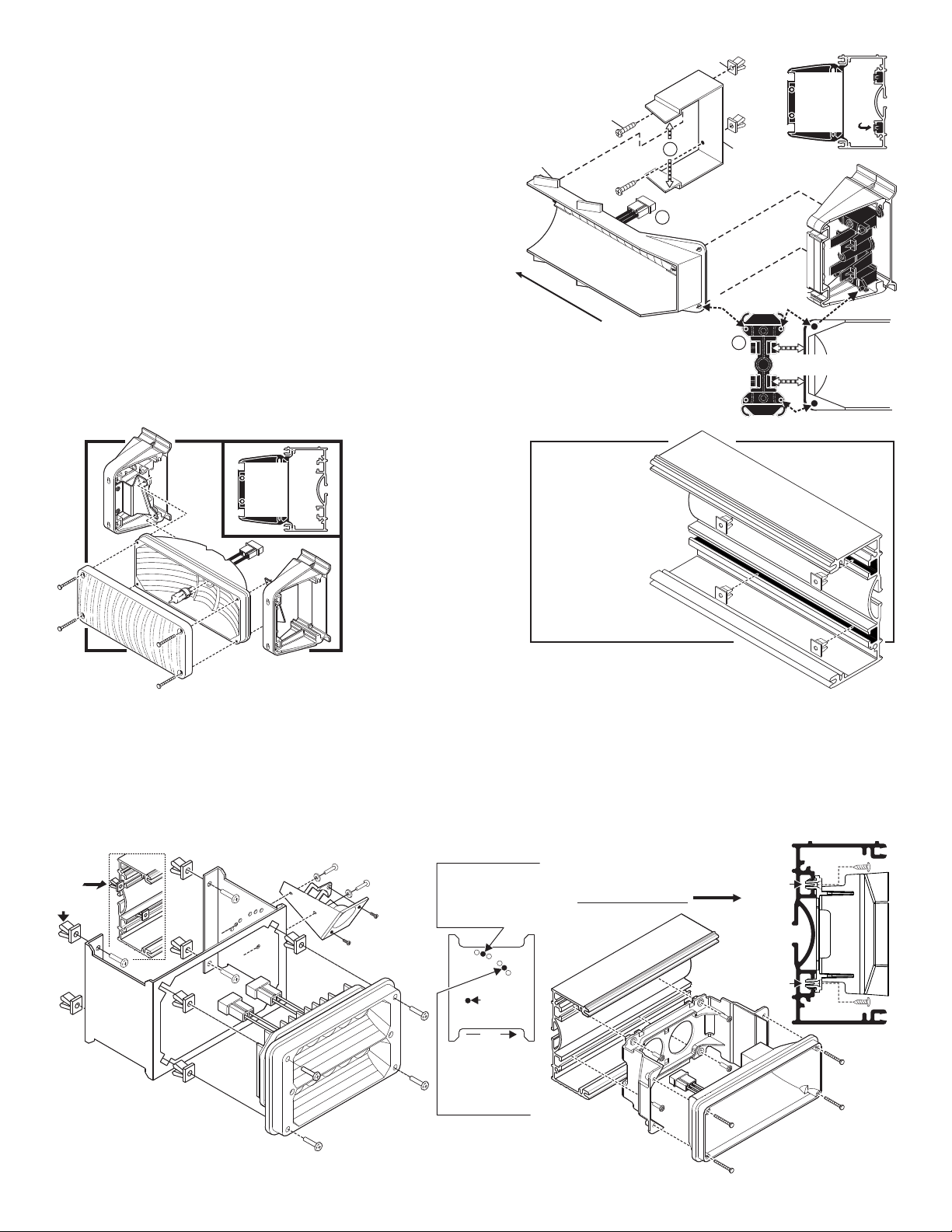
CORNER
STROBE
SUPPORT
BRACKET
SCREW, #6
X 3/8" PPHSMS
LIGHTHEAD
TAB
#6 FASTEX SCREW GROMMETS
(Install into lightbar base)
END OF LIGHTBAR
Bracket slides
into lightbar
LIGHTBAR BASE
Fastex
grommet
Clips snap over
edge of lighthead.
CORNER STROBE
Snap Lighthead mtg. holes
onto bosses on bracket.
Snap
Lighthead mtg. holes
onto
bosses on bracket.
B
C
Fig. 5
A
Snap Lighthead mtg. holes
onto bosses on bracket.
Fig. 7
Load
Light
Mounting
Bracket
Slide
grommets
into base
A Single light MR11
bracket (each side) is
mounted in the single
and the center hole of
the bottom 3 holes.
A Double light MR11
bracket (center mount)
is mounted in the single
and center hole of
the top 3 holes.
SIDE VIEW
OF BRACKET
Front
Single hole
400 Linear Split LED with MR11 Load Light / TA only
Fig. 8
Side view / Base Extrusion
Housing
snaps
into base
extrusion
Housing
is then
secured
to base
using
supplied
screws
Halogen, Strobe or LED
Lighthead
(
New style housing
)
3. Now pull the clips back on the mounting bracket that secure the lighthead as
Fig. 6
Options secure to
fastex grommets
inserted into extrusion.
Installing
Options into
Extrusion
you lift the lighthead off of the raised bosses on the bracket (Fig. 4).
4. Being careful not to pull out any wires, lift the lighthead out of the lightbar base,
disconnect its connector from the lightbar wiring harness, then lift the lighthead out
of the lightbar.
5. To reinstall the lighthead, plug the lightheads connector into the lightbar, snap
it back into the brackets and replace any lenses or lenscaps you removed.
Corner Strobe / Removal:
1. Disconnect the lightbar from it’s power source and remove the endcap in front of
the lighthead you wish to replace or service (See strobe warning).
2. Spread the ends of the corner strobe support bracket (A) apart to disengage it
from the tab on the lighthead, and lift this end of the lighthead out (Fig. 5).
3. Pull the clips back on the mounting bracket (B) as you lift the lighthead off of
the two raised bosses on the bracket, then carefully lift the lighthead out of the
lightbar base and disconnect the power cord (C), and remove the lighthead from the
lightbar.
Corner Strobe / Installation:
1. Plug the lighthead into the wiring harness (C).
2. Insert the end of the bracket into the 2 bosses, and snap the side of the lighthead into the clips in the bracket (B), then
snap the lighthead tab into the corner strobe support bracket (A) and replace the endcap. Reconnect to power.
Halogen Lighthead,
Load Light / Rear
Facing / Removal:
1. Disconnect the lightbar from
it’s power source and
remove the lens and/or
endcap in front of the
lighthead you wish to
service.
2. Unscrew the 4 lens screws
which hold the lighthead to
its 2 brackets (Fig 6).
3. Disconnect the lighthead
from power, then remove
the lighthead from the
lightbar.
Halogen Lighthead, Load Light / Rear Facing / Installation:
1. Plug the lightheads connector into the lightbar harness.
2. Attach the lighthead (and lens) to its mounting brackets using the lens screws you removed.
3. Replace the lightbar lenses or endcaps and the installation is complete.
Page 3
Page 4

MODEL 45ADDHAL
ITEM PART NUMBER DESCRIPTION
QTY
2
3
4
5
6
1
700 REFLCT 2 WIRE 2 POS AMP.-
12V 60W SNAP-IN-LAMP-
SCREW / #6 x 1-1/4" PPHSMS
LENS CLEAR OPTIC/
BRACKET MOUNTING/
SCREW #8 x 1/2" PPHSMS/
700 SERIES HALOGEN
15-081416-080
07-284353-000
02-0484303-02
15-061416-200
34-0041987-07
02-0383709-02
68-1183582-3S
1
1
1
4
4
1
MODEL 45ADDAST
01-0440624-25
13-062C40-16J
07-26C091-000
46-0941245-00
02-0363171-00
15-061416-060
26-0215001-03
02-0484303-16
02-0342933-00
07-263103-000
CABLE ASSEMBLY - 25'
ASS'Y. / CORNER LINEAR STROBE
BRACKET / CORNER STROBE
HARNESS ASS'Y. / STROBE
SUB ASS'Y. / MOUNTING BRACKET
ASS'Y. / CORNER LINEAR STROBE
BRACKET / LIGHTHEAD MOUNTING
SCREW / #6 x 3/8" PPHSMS
SCREW GROMMET
TY WRAP - 3"
ITEM PART NUMBER DESCRIPTION
QTY
2
3
4
5
6
7
8
9
1
2
1
1
1
1
1
1
1
2
MODEL 45ADROTA
ITEM PART NUMBER DESCRIPTION
QTY
2
3
4
1
68-5463532-00
"V" MIRROR BRACKET
5
HALF MIRROR LEFT
TAPE / METALIZED
HALF MIRROR RIGHT
ROTATING REFLECTOR
ROTATOR
02-0342949-00
02-0484303-01
02-0342945-00
02-0342949-01
68-5943171-01
1
1
1
1
A/R
8
9
1
5
6
2
4
3
7
MODELS: 45ADLS8* / 45ADL8*
NOTE: When two model 45ADROTA are
placed adjacent to one another, the left
and right mirrors are replaced with the
V mirror (ITEM #5) as shown.
Rotator
shown for
reference
Rotator
shown for
reference
Left mirror
shown for
reference
5
Mounting
bracket
shown for
reference
MODEL 792H & MODEL 45000PTI
2
3
ITEM PART NUMBER DESCRIPTION
QTY QTY
4
5
6
7
8
1
07-263401-000
01-5015970-29
01-0417074-00
13-104111-063
46-0968085-25
16-100220-500
14-104066-100
15-061416-060
01-5015970-29
13-062C40-16J
1
BOLT 10-24 X 5/8" CARRIAGE S//S
ASS'Y / 3M LC EMIT CABLE / 25' CONXALL
BRACKET MOUNTING 792/4500/
MODEL 792H OPTICOM EMITER
OPTION PREWIRE PLUS FOR OPTICOM/
NUT 10-24 CAD PLATED WHIZ/
WASHER #10 FLAT .631 x .060 / THK SS//
SCREW #6 x 3/8" PPHSMS/
SCREW GROMET #6/#8 FASTEX/
MODEL 792H OPTICOM EMITER
4
4
2
2
2
1
1
3
2
1
Mounting
bracket
shown for
reference
Mounting
bracket
shown for
reference
4
TO EXTRUSION
8
4
2
7
6
5
1
3
TO
EXTRUSION
6
5
4
3
2
1
TO
EXTRUSION
SUB ASS'Y., 700 LINEARLED - AMB
SCREW, #6 x 1-1/4" PPHSMS
BRACKET, MOUNTING
SCREW, #8 x 1/2" PPHSMS
700 SERIES LINEAR LED - AMB
1
4
1
07-284353-000
02-0484303-03
15-061416-200
01-0286419412
15-081416-080
4
4
1
1
4
4
1
1
4
4
1
1
4
02-0484303-04
02-0484303-05
02-0484303-06
700 SERIES LINEAR LED - BLU
700 SERIES LINEAR LED STDY - WHT
700 SERIES LINEAR LED STDY - RED
01-0286419422
SUB ASS'Y., 700 LINEAR LED - BLU
01-0286419432
SUB ASS'Y., 700 LINEAR - WHTLED
01-0286419452
SUB ASS'Y., 700 LINEAR - REDLED
SUB ASS'Y., 700 LINEAR - GRNLED
01-0286419442
1
4
4
1
02-0484303-36
700 SERIES LINEAR LED STDY - GRN
444
1114411
4 444 4
1
1
1
1
1
SUB ASS'Y., 700 LIN STDY - GRNLED
SUB ASS'Y., 700 LIN LED STDY - RED
SUB ASS'Y., 700 LIN STDY - BLULED
SUB ASS'Y., 700 LIN STDY - AMBLED
SUB ASS'Y., 700 LIN STDY - WHTLED
01-0286419253
01-0286419233
01-0286419223
01-0286419213
01-0286419243
700 SERIES LINEAR STDY -AMBLED
02-0484303-40
700 SERIES LINEAR STDY - GRNLED
700 SERIES LINEAR STDY - BLULED
700 SERIES LINEAR STDY - WHTLED
700 SERIES LINEAR LED STDY - RED
02-0484303-43
02-0484303-41
02-0484303-42
02-0484303-44
2
3
ITEM PART NUMBER DESCRIPTION
QTY QTY QTY QTY
12
13
14
4
5
6
8
9
10
11
1
QTYQTYQTYQTYQTYQTY
2
8
7
1
TO EXTRUSION
6
5
4
1211 14
10 13
9
3
Page 4
Page 5

EXTRUSION is shown
for reference only.
3-6
3-6
15
3-6
7
11
7
10
12
8
9
6-10
3-6
2-6
2-6
6-10
Extrusion shown for reference only
MODEL 45KRS
ITEM PART NUMBER DESCRIPTION
QTY
1
2
3
4
5
6
7
8
9
BRACKET MOUNTING/
SCREW / #8 x 1/2" PPHSMS
SCREW / #6 x 1" PPHSMS
OPTION / KKK REAR STROBE PKG. 4500 SERIES
LENS / CLEAR NON OPTIC 16.57 / 4500 SERIES
LENS / RED NON OPTIC 16.57 / 4500 SERIES
LENS AMBER NON OPTIC 16.57 / 4500 SERIES/
-2
07-284353-000
02-0484303-15
68-3983799-30
68-3983799-50
15-081416-080
15-061416-160
68-3983799-10
ASS'Y 700 LINEAR REFLECTOR/
02-0362641-00
46-0941245-00
HARNESS ASS'Y. / STROBE
01-0440624-25
CABLE ASSEMBLY - 25'
46-0941248-00
HARNESS ASS'Y / STROBE CENTER
02-0483910-00
SUB ASS'Y / LOAD LIGHT 4500 SERIES
10
11
1
3
1
12
12
3
3
2
1
1
MODEL: 45FLASH
2
3
ITEM
PART NUMBER
DESCRIPTION
QTY
1
4500 OPTION / ADD INTERNAL FLASHER
ASSY / FLASHER INPUT HARNESS
ASSY / HARNESS / 400 LED with FLASHER
ASS'Y / 2 CHANNEL FLASHER / 4500 SERIES LED
1
1
1
46-0764668-00
02-0343046-00
02-0484303-32
46-0743203-00
14
1
1
2
3
1
12 13
MODEL: 45KRL
2
3
ITEM
PART NUMBER
DESCRIPTION
QTY
4
5
6
7
8
1
9
10
11
12
13
14
68-3983799-10
68-3983799-50
02-0342934-00
07-263579-000
13-062C40-16J
15-081416-080
07-284354-000
46-0784112-04
01-026B807-50
15-061416-160
01-0286361255
01-0286361211
4
2
2
4
16
8
4
1
2
2
-1
2
1
SCREW GROMET, #6/#8 FASTEX
SCREW, 8 X 1/2 PPHSMS
BRACKET, MTG 400 SERIES LIGHTHEAD
SCREW, 6X1 PPHSMS TYPE A
SUB ASS'Y, 400 LINEAR LED SPLIT / RED/RED
SUB ASS'Y, 400 LINEAR LED SPLIT / AMB/AMB
UPPER LED ADAPTER
LENS, AMBER NON OPTIC 16.57"/4500 SERIES
LENS, RED NON OPTIC 16.57"/4500 SERIES
SUB ASS'Y, BRACKET & BASE
BRACKET, SUPPORT CORNER STROBE
ASS'Y CORNER LED RED AMP/4500 SERIES
02-0483910-00
SUB ASS'Y, LOAD LIGHTS /4500 SERIES
4
15-061416-060
SCREW, 6 X 3/8 PPHSMS 410 SS TYPE A
OPTION KKK LED PACKAGE/ REAR
02-0484303-18
3-6
NOTE: Lightheads shown in standard
positions.
LOAD LIGHTS: position adjacent to
CENTER LEDs.
6
MODEL 45ADDSTR
ITEM
PART NUMBER DESCRIPTION
QTY
700 LINEAR REFLECTOR
SCREW, #6 x 1" PPHSMS
BRACKET, MOUNTING
SCREW, #8 x 1/2" PPHSMS
4
4
07-284353-000
15-061416-160
02-0362641-00
15-081416-080
46-0941245-00
HARNESS ASS'Y., STROBE
1
01-0440624-25
CABLE ASSEMBLY - 25'
A/R
46-0941248-00
HARNESS STROBE CTR
2
3
4
5
6
7
1
700 SERIES LINEAR STROBE
A/R
1
02-0484303-07
1
1
TO
EXTRUSION
4
7
3
5
2
7
MODEL: 45LRLOAD
POWER TO PASSENGER
SIDE LOAD LIGHT.
2
11
8
6
5
4
3
1
12
13
9
10
LR11 LOAD LIGHT OPTION
2
6
2
6
6
6
02-0484303-48
07-286741-000
56-043625-000
07-26C834-000
68-5944082-31
02-016B644-30
68-7744081-00
BRACKET, MTG LR11 LOAD LT DBL 4500
THERMAL PAD, CO-THERM LR11
REFLECTOR, TIR LR11 LOAD LIGHT 4500
DIFFUSER, LR11 LOAD LIGHT 4500 SERIES
18
8
8
13-062C40-16J
14-062216-160
15-061416-060
SCREW GROMMET, #6/#8 FASTEX
SCREW, 6 X 3/8 PPHSMS 410 SS TYPE A
6
39-0402313-04
HOUSING, 2 POS PIN COMM MATE-N-LOK
BRACLET, MTG LR11 LOAD LT SNGL 4500
PCB 3 LED LR11 WHT ALLEY/TD XP-E
4
14-062216-061
SCREW, 6-32 X 3/8 PPHMS SEMS W/IT LK WSHR SS
SCREW, 6-32 X 1" PPHMS SS
1
2
46-0744083-00
46-0941243-00
ASSY, HARNESS LR11 LOAD LIGHT 4500
ASS'Y, SCENE LIGHT HARNESS
02-0484303-50
LR11 LOAD LIGHT W/O INPUT HARNESS
2
2
6
6
6
6
18
8
8
6
4
2
ITEM
PART NUMBER
DESCRIPTION
QTY QTY
2
3
11
12
13
4
5
6
7
8
9
10
1
13
POWER TO
PASSENGER
SIDE LOAD
LIGHT.
7
6
8
4
2
3
5
10
9
12
11
1
LR11 LOAD LT OPT. 13 DEGREE
02-0484303-51
07-286741-000
56-043625-000
07-26C834-000
68-5944082-31
02-016B644-30
68-7744081-00
BRKT, MTG LR11 LOAD LT DBL 4500
THERMAL PAD, CO-THERM LR11
REFLECTOR, TIR LR11 LOAD LT 4500
DIFFUSER, LR11 LOAD LT 4500 SERIES
13-062C40-16J
14-062216-160
15-061416-060
SCREW GROMMET, #6/#8 FASTEX
SCREW, 6 X 3/8 PPHSMS 410 SS TYPE A
39-0402313-04
HSNG, 2 POS PIN COMM MATE-N-LOK
BRKT, MTG LR11 LOAD LT SNGL 4500
PCB 3 LED LR11 WHT ALLEY/TAKEDN XP-E
14-062216-061
SCREW, 6-32 X 3/8 PPHMS SEMS W/IT LOCK WSHR SS
SCREW, 6-32 X 1" PPHMS SS
46-0744083-00
46-0941243-00
HARNESS LR11 LOAD LIGHT 4500
ASS'Y, SCENE LIGHT HARNESS
MODEL: 45LRLOAD / 13 DEGREE
2
3
ITEM
PART NUMBER
DESCRIPTION
QTY
4
5
6
7
8
1
9
10
11
4
2
6
2
6
6
6
18
8
6
8
1
2
12
13
Page 5
Page 6

MODEL: 45ADRB*
2
3
ITEM
PART NUMBER
DESCRIPTION
QTY
1
4500 SOLID STATE ROTATOR
SOLID STATE ROTATOR
414
01-026E607-_0
02-0484303-__
SCREW GROMMET
13-062C40-16J
SCREW, #6 x 3/8" PPHSMS
15-061416-060
GREY
WHT/ORG
VIOLET
WHT/VIO
BLK
RED
3
6
5
4
2
1
1
2
1
2
4500
HARNESS
CUSTOMERS
WIRING
(OPTIONAL)
TO ROTATOR
CRUISE
POWER
GROUND
SCANLOCK
SYNC
LOW POWER
4
3
MODEL 45KFH
ASS'Y. 12V 60W SNAP-IN-LAMP/-
ASS'Y. 700 REFLECTOR 2 WIRE/2 POS AMP/
KKK FRONT HALOGEN PKG. 4500 SERIES
LENS RED NON OPTIC 16.57 / 4500 SERIES/
LENS CLEAR NON OPTIC 16.57 / 4500 SERIES/
68-3983799-30
02-0484303-120
68-3983799-50
SCREW #6 x 1-1/4" PPHSMS/
LENS CLEAR OPTIC/
SCREW #8 x 1/2" PPHSMS/
BRACKET MOUNTING/
34-0041987-07
68-1183582-3S
15-061416-200
02-0383709-02
15-081416-080
07-284353-000
ITEM PART NUMBER DESCRIPTION
QTY
2
3
4
5
6
1
3
3
12
12
1
-1
7
8
3
3
MODEL: 45KFL
6-10
11 12
6-10
2-6
3-6
2-6
3-6
1
1
MODEL: 45FL*
1
1
1
1
1
2
3
DESCRIPTION
4
5
6
7
8
1
1111
4444
9
QTY
1
4
22222
11111
1
PART NUMBER
QTY QTY QTY QTY
02-0484303-30
02-0484303-29
02-0484303-27
02-0484303-28
02-0484303-31
15-081416-080
07-284354-000
15-061416-160
01-0386361222
01-0386361211
46-0784112-04
01-0386361244
01-0386361255
01-0386361233
8 X 1/2 PPHSMS
6 X 1 PPHSMS TYPE "A"
400 LINEAR LED AMB AMP
400 LINEAR LED BLU AMP
400 LINEAR LED WHT AMP
400 LINEAR LED GRN AMP
400 LINEAR LED RED AMP
S. ASY / 400 LED SPLIT RED-RED
S ASY 400 LED SPLIT GRN GRN./ -
S ASY 400 LED SPLIT WH WH./ T-T
S ASY 400 LED SPLIT BLU BLU./ -
BRACKET MTG 400 LTHD/
S ASY 400 LED SPLIT AMB AMB./ -
HARNESS UPPER LED ADAPT/.
NOTE: Lightheads shown in standard positions.
Position Load Lights adjacent to center halogen.
MODEL 45KRH
LENS / AMB NON OPTIC 16.57 / 4500 SER.
BRACKET MOUNTING/
LENS CLEAR OPTIC/
SCREW #8 x 1/2" PPHSMS/
700 REFLECTOR 2 WIRE 2 POS AMP/
ASS'Y. 12V/60W SNAP-IN-LAMP/
SCREW #6 x 1-1/4" PPHSMS/
KKK REAR HALOGEN PKG. 4500 SER.
LENS CLR NON OPTIC 16.57 / 4500 SER/.
LENS / RED NON OPTIC 16.57 / 4500 SER.
07-284353-000
68-1183582-3S
02-0484303-14
68-3983799-30
68-3983799-50
68-3983799-10
15-081416-080
02-0383709-02
15-061416-200
34-0041987-07
ITEM PART NUMBER DESCRIPTION
QTY
2
3
4
5
6
1
7
8
9
333
12
1
-2
12
3
1
SUB ASS'Y / LOAD LIGHTS / 4500 SER.
02-0483910-00
10
1
15
1
3-8
3-8
2
9
3-8
10
SCREW 6X1 PPHSMS TYPE A/
UPPER LED ADAPTER
OPTION KKK FRONT LED PACKAGE/
SUB ASS'Y 400 LINEAR LED SPLIT / WHT-WHT/
SUB ASS'Y 400 LINEAR LED SPLIT / RED RED/-
12
2
2
2
16
4
4
ASS'Y CORNER LED RED AMP 4500 SERIES/
SCREW 6X3/8 PPHSMS 410 SS TYPE A//
SCREW GROMET #6 #8 FASTEX/-
15-061416-060
15-061416-160
01-026B807-50
02-0484303-17
02-0386361233
02-0386361255
46-0784112-04
13-062C40-16
4
07-284354-00
BRACKET MTG 400 SERIES LIGHTHEAD/
68-3983799-30
68-3983799-50
02-0342934-00
07-26C091-000
1
2-12
LENS / CLEAR NON OPTIC 16.57" 4500 SERIES/
LENS RED NON OPTIC 16.57" 4500 SERIES//
SUB ASS'Y BRACKET & BASE/
BRACKET CORNER STROBE/
2
3
ITEM
PART NUMBER
DESCRIPTION
QTY
4
5
6
7
8
1
9
10
11
12
TO
EXTRUSION
TO
EXTRUSION
TO
EXTRUSION
1
3-8
2
3-8
TO
EXTRUSION
8
2
9
3
1
5
6
7
4
Lightheads shown in standard
positions. Extrusion shown
for reference only.
TO
EXTRUSION
1
2
3
Page 6
Page 7

8
1
7
LOAD
LIGHT
Wire Harness / MR11 Load Lights
Extrusion
To Control Head
(not shown)
For Reference
For Reference
Grommet shown for reference
FLASHER
TA
NOTE: Model 45TA8
shown. For Model 45TA6
drop out the center two
lightheads.
EXTRUSION,
CORNER LEDs and
CENTER LENS are shown
for reference only.
2 1
1 2
WHT/RED
WHT/RED
RED
RED
WHT/ORG
YELLOW
WHT/YEL
ORANGE
CABLE ASSY
BLUE
WHT/GRN
WHT/BLU
GREEN
LOAD
LIGHT
VIOLET
WHT/VIO
WHT/VIO
VIOLET
2 1
1 2
2 1
2 1
1 2
2 1
1 2
2 1
1 2
2 1
1 2
2 1
1 2
2 1
1 2
2 1
1 2
2 1
1 2
2 1
1 2
2 1
1 2
2 1
1 2
2 1
1 2
2 1
1 2
2 1
1 2
2 1
1 2
2 1
1 2
1 21 2 1 2 1 2
123
321
123
321
123
321
BLACK
BLUE
2 1 2 1 2 1 2 1 2 1 2 1
RED
RED
RED
RED
TA1
TA1
TA2
AMB
TA3
AMB
TA4
AMB
TA5
AMB
TA6
TA6
GRN
BLK
8
9
RED
RED
RED
RED
TRAFFIC ADVISOR OPTION W/MR-11 LOAD LIGHTS
4
5
1
4 4 4 4 4 4 4
07-284353-000
15-061416-160
02-0362641-00
15-081416-080
46-0941245-00
01-0440624-25
68-3983799-30
68-3983799-50
02-0484303-13
ASS'Y 700 LINEAR REFLECTOR/
SCREW #6 x 1" PPHSMS/
SCREW #8 x 1/2" PPHSMS/
HARNESS ASS'Y STROBE/
CABLE ASSEMBLY - 25'
LENS CLEAR NON OPTIC 16.57 / 4500 SERIES/
LENS RED NON OPTIC 16.57 / 4500 SERIES/
BRACKET MOUNTING/
46-0941248-00
HARNESS ASS'Y / STROBE CENTER
MODEL 45KFS
ITEM PART NUMBER DESCRIPTION
QTY
2
3
4
5
6
7
8
1
9
1
-1
3
3
12
12
2
3
1
KKK FRONT STROBE PKG. 4500 SERIES
5-9
5-9
5-9
5-9
4
2
3
9
5
4
7
8
6
3 3
10
11
5-9
5-9
5-9
MODEL: 45TA with MR11 Load Lights
2
3
DESCRIPTION
4
5
6
7
1
8
02-0484303-35
PART NUMBER
QTY
1
1
2
6
1
1
01-0269809-06
01-0669813-00
02-0342933-00
02-0386361211
02-0463931-00
46-0743112-00
1
1
1
46-0769810-05
46-0743119-00
4500 T/A FLASHER 6 LAMP
400 LIN. LED SPLT AMB AMB-
TADCTL1 CTRLHD DOMINATOR TA/
SUB ASS'Y MOUNTING BRACKET/
MR11 LOAD LTS / 4500 SERIES
HARNESS MR11 LOAD LIGHTS
CABLE T/A OPTION
HARNESS 4500 TA6 DBL RED-ORG-YEL//
MODEL 45TA MR11 LOAD LTS/
46-0769810-06
HARNESS 4500 TA6 DBL VIO BLU GRN//--
9
6
MODELS: 45TA6 / 45TA8
ITEM PART NUMBER DESCRIPTION
QTY QTY
1
2
1
3-6
3-6
7
7
3-6
7
9
5
1
4
MOUNTING BRKT. 400 . LTHD
SUB AS'Y / 400 LED SPLIT AMB-AMB
SCREW / #6 X 1" PPHSMS
4500 INTERNAL HARNESS / TA
8 LAMP TA/ 4500 SERIES
HOUSING / AMP 12 POS. PIN
6 LAMP TA/ 4500 SERIES
TA CONTROL HEAD 12V LED
CABLE ASS'Y / 9-C 35' 4" STRIP
39-0412014-14
07-284354-000
15-061416-160
01-0386361211
01-0683850-00
46-0784545-00
46-0741346-35
Y HARNESS 6" ASSEMBLY
SCREW / #8 X 1/2" PPHSMS
WASHER 1/2" I.D.
16-1766430-08
46-0784112-04
15-081416-080
26-0121053-00
CLAMP 3/8"
2
3
4
5
6
7
8
1
02-0484303-34
02-0484303-33
1
9
10
11
1
1
2
24
6
6
12
6
1
1
1
1
1
2
32
8
8
16
8
1
1
Page 7
Page 8

OPTION GTT EMITTER
ITEM PART NUMBER DESCRIPTION
QTY
2
3
4
5
6
1
15-061416-060
13-062C40-16J
46-0743825-25
07-26B390-023
01-1317921-01
02-0484303-39
15-045216-060
1
REF
4
1
4
4
GTT LED EMITTER
MTG BRKT GTT LED MODULE
SCREW, #6 X 3/8" PPHSMS
SCREW GROMET, #6 / #8 FASTEX
CABLE GTT LED EMITTER 25'
SCREW, 4 X 3/8 PFH PLASTI-LOC
EMITTER, LED GTT
32 33
34
35
23
24
19
25
17
18
22
32 33
34
35
32 33
34
35
14
26 27
28
31
31
30
30
31
30
31
16
15
30
28
29
12
3
13 37
4
56
12
89
7
10 11
CAUTION! DO NOT LOOK DIRECTLY AT
THESE LED’S WHILE THEY ARE ON.
MOMENTAR Y BLINDNESS AND/OR EYE
DAMAGE COULD RESULT!
IMPORTANT WARNING!
1 2
12
12
12
Length of Lightbar
ICC Light Requirements
01-0684303___
PART NUMBER KEY:
ICC LIGHT REQUIREMENTS
1 = A =
R =
Without ICC Lights With AMB ICC Lights
With RED ICC Lights
NOTE: 52", 60" & 72" Lightbars available
without ICC Lights or with Center ICC Lights
only (RED or AMBER)
1 2
1 2
1 2
GREEN
BLK/WHT
BLK/WHT
RED
VIOLET
BLACK
ORANGE
GREY
BLACK
ROTATOR
LED or
HALOGEN
ROTATOR
LED or
HALOGEN
ROTATOR
LED or
HALOGEN
ROTATOR
LED or
HALOGEN
ROTATOR
LED or
HALOGEN
ROTATOR
LED or
HALOGEN
ROTATOR
LED or
HALOGEN
1 21 21 2 1 2 1 2 1 2
BLK/WHT
BLACK
BROWN
YELLOW
BLK/WHT
1 2
BLACK
ROTATOR
LED or
HALOGEN
1 2
BLUE
4500 SERIES WIRING
36
YEL +12VDC/
VIO +12VDC/
BLK/WHT GND/
BLK/WHT GND/
BLK GND/
BRN +12VDC/
RED +12VDC/
GRN / +12VDC
BLK/WHT GND/
BLU +12VDC/
BLK GND/
ORG +12VDC/
BLK G D/N
BLK GROUND/
BLK GND/
GRY +12VDC/
ROTATOR
L E D o r
HALOGEN
(
OUTBOARD
)
ROTATOR
LED or
HALOGEN
INBOARD
()
ROTATOR
LED or
HALOGEN
CENTER
()
ROTATOR
LED or
HALOGEN
(INBOARD)
1212121212121212
21
01-0684303122
01-0684303138
01-0684303144
01-0684303_76
01-0684303_82
01-0684303_72
01-0684303_60
01-0684303_84
01-0684303_86
01-0684303_90
01-0684303_88
11-463582-100
EXTRUSION, 17.31" ICC MTG. HOLESw
ithout
1
01-0684303_52
EXTRUSION, 33.67" ICC MTG. HOLESw
ithout
11-463582-106
1
1
11-463582-109
1
11-463582-001
1
1
1
1
1
1
1
1
11-463582-027
EXTRUSION, 39.67" ICC MTG. HOLESw
ithout
EXTRUSION, 47.67" withICC MTG. HOLES
11-463582-016
EXTRUSION, 55.67" with ICC MTG. HOLES
11-463582-002
EXTRUSION, 67.67" with ICC MTG. HOLES
11-463582-023
EXTRUSION, 71.67" with ICC MTG. HOLES
222222222222
02-0342932-00
MOUNTING BASE ASSEMBLY
11-463582-003
EXTRUSION, 77.67" with ICC MTG. HOLES
11-463582-005
EXTRUSION, 79.67" with ICC MTG. HOLES
11-463582-026
EXTRUSION, 81.67" with ICC MTG. HOLES
EXTRUSION, 83.67" with ICC MTG. HOLES
11-463582-028
EXTRUSION, 85.67" with ICC MTG. HOLES
444444444444
14-104286-16J
SCREW, #10-24 x 1.25" SHOULDER PHTX TRI PT
44444444444
2
01-0441771-00
KIT, EXTRUSION STEP BOLT MTG. 1-1/4"
111111111111
10-0522977-01
LABEL, P/N/M/N/S/N
1
21122121211221212112211
21-11263204-0
02-0320397-00
GROMMET, 1" SLIM LINE
LOUVER, 1" W/FILTER
686
13.61
2222
3
5
666
11.28 9.28 7.94
9.46
22222
1
33
5.616.61
8.13 7.13
2.88
4.44
222
MOUNTING BRACKET ASSEMBLY
02-0342933-00
38-0316275-00
38-0522954-00
GASKET, REAR EXTRUSION
SEAL, CORD 3/16"
68-3983813-**
LENSCAP
14.27
15.7915.46
13.94
15.13
14.80
13.28
14.47
12.95
13.47
11.95
12.8010.80
8
A/R A/R
68-3963615-**
LENSCAP, SPLIT
444444444444
15-06121B-082
SCREW, #6 x 1/2" PPHSMS (BLACK)
77
55
8866
555
4
222
-
666
5
333
1
68-3983799-**
02-0342941-00
A/R
16
A/R
A/R16A/R
12
A/R A/R
A/R
12
A/R
A/R
12
A/R
12
12
10 6 6 6
2
02-0483903-A0
15-08121B-082
02-0483903-R0
A/R
A/R
A/R A/R
02-0483903CA0
A/R
A/R A/R A/R
02-0483903CR0
A/R A/RA/R A/R A/R A/RA/R A/R A/R A/R
46-0764014-00
1111 1111
01-0684303_94
1
11-463582-030
EXTRUSION, 89.67" with ICC MTG. HOLES
A/R A/R A/R A/R A/R A/R A/R A/R A/R A/R
21-3117552-00
HOLE PLUG, 9.65MM GROOVE DIA./RUBBER BLK
11
46-0941569-00
ASS'Y, CENTER ROTATORS, HARNESS
222
46-0941244-00
ASS'Y, ROTATORS HARNESS
2
4
4
1
1
2
2
A/R
4
1
A/R
A/R
7
16.46
14.94
8
8
16
1
A/R
4
2
4
A/R
2
1
14.61
16.13
8
2
16
7
4
8
A/R
A/R
1
01-0684303_92
11-463582-029
1
EXTRUSION, 87.67" WITH ICC MTG. HOLES
2
3
ITEM
PART NUMBER
DESCRIPTION
QTYQTY QTYQTY QTY QTY QTY
11
12
13
14
15
16
20
28
17
25
21
29
18
26
22
30
19
27
23
31
24
32
4
5
6
7
8
9
10
1
33
QTYQTYQTY QTY QTY QTY QTY
34
35
36
LENS
ASS'Y LENS GASKET/RETAINER/
ASS'Y LED ICC LIGHTS - AMBER/
SCREW #8 x 1/2" PPHSMS BLACK//
ASS'Y LED ICC BRAKE LIGHTS - RED//
ASS'Y C R LED ICC LIGHTS - AMBER/T
ASS'Y C R LED ICC BRAKE LTS - RED/T /
ASS'Y / HARNESS
4500 SERIES LT BAR-22" w
ithout ICC LT.
4500 SERIES LT BAR-38"
without ICC LT.
4500 SERIES LT BAR-44""
without ICC LT.
4500 SERIES LT BAR-52"
/ See P/N Key
4500 SERIES LT BAR-60"
/ See P/N Key
4500 SERIES LT BAR-72"
/ See P/N Key
4500 SERIES LT BAR-76"
/ See P/N Key
4500 SERIES LT BAR-82"
/ See P/N Key
4500 SERIES LT BAR-84"
/ See P/N Key
4500 SERIES LT BAR-86"
/ See P/N Key
4500 SERIES LT BAR-88"
/ See P/N Key
4500 SERIES LT BAR-90"
/ See P/N Key
4500 SERIES LT BAR-94"
/ See P/N Key
4500 SERIES LT BAR-92"
/ See P/N Key
37
5
4
3
2
1
6
Page 8
 Loading...