

Page 1
®
ENGINEERING COMPANY INC.
51 Winthrop Road
Chester, Connecticut 06412-0684
295SLS*6 Siren Amplifier
Installation Guide:
Phone: (860) 526-9504
Fax: (860) 526-4078
Internet: www.whelen.com
Sales e-mail: autosale@whelen.com
Canadian Sales e-mail: canadiansales@whelen.com
Customer Service e-mail: custserv@whelen.com
DANGER! Sirens produce extremely loud emergency warning tones! Exposure to these tones without
proper and adequate hearing protection, could cause ear damage and/or hearing loss! The Occupational Safety &
Health Administration (www.osha.gov) provides information necessary to determine safe exposure times in
Occupational Noise Exposure Section 1910.95. Until you have determined the safe exposure times for your
specific application, operators and anyone else in the immediate vicinity should be required to wear an approved
hearing protection device. FAILURE TO FOLLOW THIS RECOMMENDATION COULD CAUSE HEARING LOSS!
Safety First
This document provides all the necessary information to allow your Whelen product to be properly and safely installed.
Before beginning the installation and/or operation of your new product, the installation technician and operator must
read this manual completely. Important information is contained herein that could prevent serious injury or damage.
• Proper installation of this product requires the installer to have a good understanding of automotive electronics,
systems and procedures.
• Failure to use specified installation parts and/or hardware will void the product warranty!
• If mounting this product requires drilling holes, the installer MUST be sure that no vehicle components or other
vital parts could be damaged by the drilling process. Check both sides of the mounting surface before drilling
begins. Also de-burr any holes and remove any metal shards or remnants. Install grommets into all wire
passage holes.
• If this manual states that this product may be mounted with suction cups, magnets, tape or Velcro®, clean the
mounting surface with a 50/50 mix of isopropyl alcohol and water and dry thoroughly.
• Do not install this product or route any wires in the deployment area of your air bag. Equipment mounted or
located in the air bag deployment area will damage or reduce the effectiveness of the air bag, or become a
projectile that could cause serious personal injury or death. Refer to your vehicle owner’s manual for the air bag
deployment area. The User/Installer assumes full responsibility to determine proper mounting location, based
on providing ultimate safety to all passengers inside the vehicle.
• For this product to operate at optimum efficiency, a good electrical connection to chassis ground must be
made. The recommended procedure requires the product ground wire to be connected directly to the NEGATIVE
(-) battery post.
• If this product uses a remote device to activate or control this product, make sure this control is located in an
area that allows both the vehicle and the control to be operated safely in any driving condition. DO NOT
ATTEMPT TO ACTIVATE OR CONTROL THIS DEVICE IN A HAZARDOUS DRIVING SITUATION.
• It is recommended that these instructions be stored in a safe place and
referred to when performing maintenance and/or reinstallation of this
product.
• FAILURE TO FOLLOW THESE SAFETY PRECAUTIONS AND
INSTRUCTIONS COULD RESULT IN DAMAGE TO THE PRODUCT OR
VEHICLE AND/OR SERIOUS INJURY TO YOU AND YOUR PASSENGERS!
ACTIVATION OF THIS
SIREN MAY DAMAGE
UNPROTECTED EARS!
CAUTION
Loud siren noise can cause
hearing damage and/or loss.
Wear
Refer to OSHA Section 1910.95 prior
Protection!
to putting ANY siren into service!
Automotive: Sirens/Switches
For warranty information regarding this product, visit www.whelen.com/warranty
©2008 Whelen Engineering Company Inc.
Form No.14130E (031610)
Page 1
Page 2
Congratulations on selecting the 295SLS-Series Siren. This series offers a unique collection of features designed to allow the user to
customize the operation of this siren to suit their individual needs. Features include:
• Programmable Power Distribution Switches
• Power to drive two, 100-Watt Speakers
• Scan-Lock™ Power Distribution & Siren Tone
Programing
• Siren Interruption Control
• High and Low Voltage Shutdown
• Program the Siren Tone and the Override Tone of
any Rotary switch position
• Enabling or Disabling Auxiliary Siren from the
power distribution control switches
• Power distribution control switch type
selection (push on push off, momentary,
flashing, timed output)
• Auxiliary Input Control
• Hands-Free Operation
• Horn Ring Transfer
• Simulated mechanical Siren Tones
• Speaker Diagnostics
• “Siren In Use” Output
• LED Backlighting
1.0 Mounting:
This siren is designed to be mounted directly onto the dash or other surface through
the use of a bail strap mounting bracket. The unit may also be mounted into your
vehicle’s console (if so equipped).
WARNING: Regardless of the style selected, be sure to observe the air bag
warning on the cover of this manual.
WARNING: Mounting this unit will require drilling. It is absolutely necessary to
make sure that no other vehicle components could be damaged in the process.
Check both sides of the mounting surface before starting. If damage is likely,
select a different location.
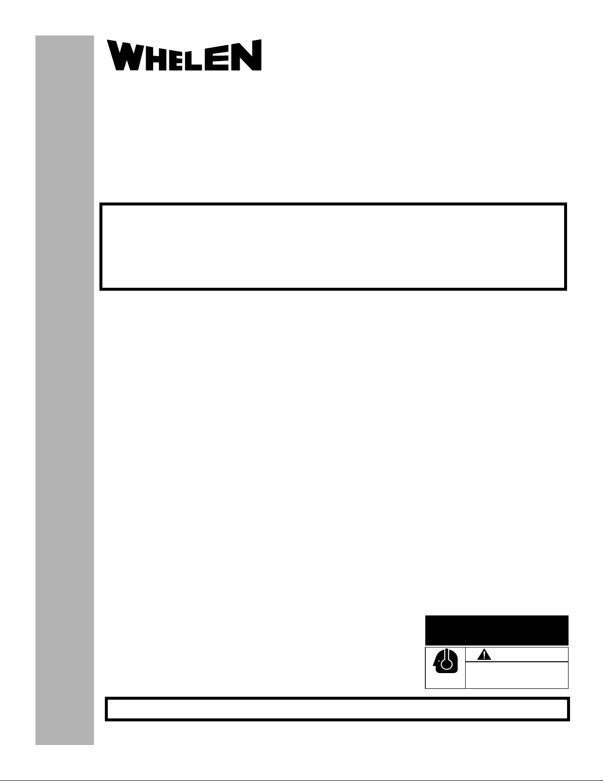
1.1 Bail Strap Mount:
1. Position bail strap in selected mounting location
and drill mounting holes, then secure the
bail strap to the vehicle.
2. Secure the siren to the bail strap as
shown. Tighten the acorn nuts firmly.
1.2 Console Mount:
Console manufacturers offer mounting kits that
Fig. 1
include all the necessary hardware and brackets
required to mount this unit into their console. The console
mount brackets are secured onto the unit in the same way.
Please refer to the manual included with your console.
1.3 Microphone Clip:
A microphone clip is included with this product.
WARNING: Refer to the Air Bag Warning before installing this clip.
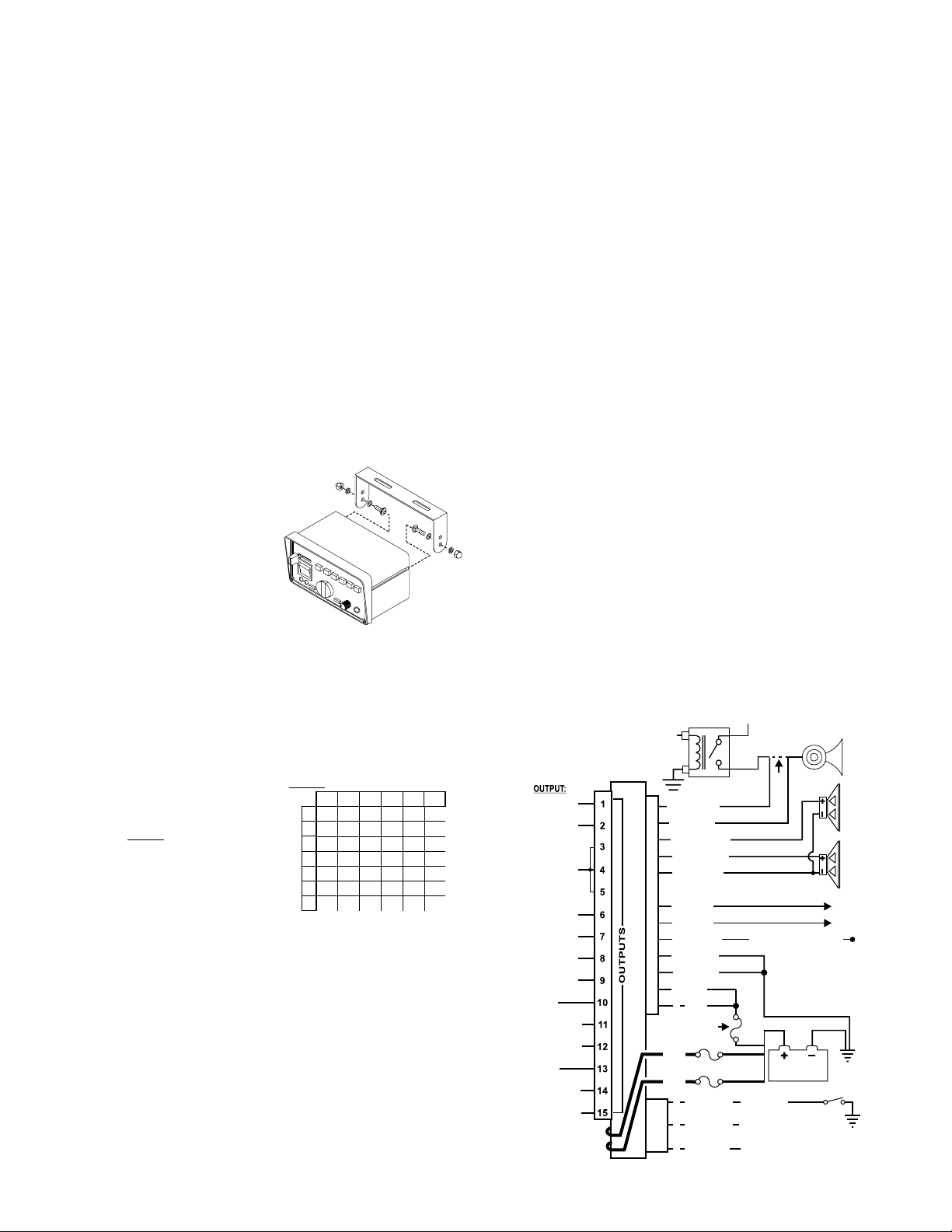
2.0 Wiring:
2.1 Siren Input Connector - RED: Power - BLACK: Ground
WARNING: All customer supplied wires
that connect to the positive terminal of
the battery must be sized to supply at
least 125% of the maximum operating
current and FUSED
at the battery to
carry that load. DO NOT USE CIRCUIT
BREAKERS WITH THIS PRODUCT!
1. Splice the 2 RED (Power) wires
together, then extend this single RED
wire toward the vehicle battery. Splice
the 2 BLACK (Ground) wires together and extend this single BLACK wire
toward the vehicle battery. To pass the RED and BLACK wires through, you
may have to drill a hole in the firewall. Insert a grommet to protect the wires.
2. Route the RED and BLACK wires along the factory harness towards the
battery and install a fuse block (user supplied) on the end of the RED wire.
Remove fuse from fuse block before connecting any wires to battery.
3. Connect fuse block wire to POSITIVE terminal on battery. There must not be
more than 2 feet of wire between fuse block and battery. The wire between the
4. fuse and battery is “unprotected”, do not allow it to chafe and short to ground.
Connect the BLACK wire to the factory chassis ground.
ORANGE, YELLOW & BROWN - Speaker Wires
1. Route the ORANGE, YELLOW and BROWN wires toward vehicle siren
speakers, along factory wire harness and through firewall at the same point as
the RED and BLACK wires.
TABLE 1
30
40
50
60
70
Current Draw / AMPS
80
Wire Gauge / AWG
10
12
24.5
15.5
10.5
16.5
7.5
12.5
10
6
5
8
7
4.5
6 10 15.5 24.5
4
8
6
396298.5
26
41.5
49.5
19.5
31
39.5
25
15.5
20.5
13
17.5
11
42
15720
104
66
78.5
63
52.5
33
28
45
39
• Harmonically-rich, composite Airhorn Tones
• Title 13-Compliant Profiles
• Non-destructive Short Circuit Protection
• Meets Class A Sound Requirements
• External Back-light Control
• Radio Repeat
• Copy one units configuration to another unit
• Easy reset to default settings
• Power Distribution fuses included
2. Connect the YELLOW wire to the POSITIVE terminal on SPEAKER #1 and the
ORANGE wire to the POSITIVE terminal on SPEAKER #2. NOTE: For single
speaker installations use the YELLOW wire and cap the ORANGE wire.
3. Connect BROWN wire to NEGATIVE connection on speakers #1 & 2.
WHITE & GREY - Horn Relay Wires:
1. Route WHITE and GREY wires along factory wire harness and through firewall
at the same point as the RED and BLACK wires.
2. Route WHITE and GREY wires to vehicle’s horn relay. If possible, follow the
factory wire harness to this relay.
3. Locate the wire that connects the vehicle horn to the horn relay and cut it.
4. Connect the WHITE wire to the wire coming from the horn relay.
5. Connect the GREY wire to the wire coming from the horn.
Two BLUE wires - Radio Rebroadcast (optional):
The two remaining BLUE wires are used to connect your two-way radio’s
external speaker for radio rebroadcast (optional connection).
Note: If your remote speaker is amplified (speaker has a power amp circuit),
radio rebroadcast will not work and should not be used.
1. Locate the 2 wires that connect the external speaker to the 2-way radio, cut
one of them and splice one of the BLUE wires into this circuit.
2. Cut the remaining speaker wire and splice the other BLUE wire into this circuit.
VIOLET - Siren Interruption:
Grounding the VIOLET wire will deactivate the siren. The siren can be programmed
to reactivate the tones by 2 different methods (See section 6.8) This wire doesn’t
affect HORN or MAN push button operations.
HORN
WIRING
DIAGRAM
BUTTON
TO HORN
RELAY
+12V
Fig. 2
CUT WIRE
Siren interruption
Ground to activate.
BATTERY
Auxilliary Enable
(
)
Optional
“Siren In Use" Icon
Input on Video Camera
Backlight
Control Voltage (+12 VDC)
Distance is shown in feet.
Page 2
20 AMP OUTPUT
20 AMP OUTPUT
20 AMP OUTPUT
15 AMP OUTPUT
15 AMP OUTPUT
15 AMP OUTPUT
15 AMP OUTPUT
AUX INPUT
AUX OUTPUT NC
AUX OUTPUT NO
AUX INPUT
AUX OUTPUT NC
AUX OUTPUT NO
11 WHITE
10 GREY
12 YELLOW
8 ORANGE
7 BROWN
3 BLUE
6 BLUE
9 VIOLET
SIREN INPUT CONNECTOR
5 BLACK
2 BLACK
4 RED
1 RED
20 AMP FUSE
Siren Amplifier
RED
Both RED Wires: 60 AMP FUSE
RED
3 WHT/GRN
2 WHT/ORG
3-POS.
INPUT CONN.
1 WHT/YEL
VEHICLE
100W
100W
RADIO
TO 2-WAY
CHASSIS
GROUND
HORN
#1
SPEAKER
#2
SPEAKER
SPEAKER
Page 3

3 Pos. Slide Switch: 0 = Off 1 Controls Terminal 1
2 Controls Terminal 2 3 Controls Terminals 3, 4 & 5
Controls
Controls
Terminal
Power
Switch
Terminal
Manual
6
Rotary
Switch
7
Radio Repeat
Adjusts volume
Programmable Power
Distribution Control
Controls
Controls
Terminal
Terminal
8
9
Controls
Terminal
10-11-12
Air
Horn
Controls
Terminal
s
13-14-15
Microphone
Volume
Rear View of Siren
Mic.
Input
Push Buttons
6
15
14 12
5
13
1112
3 Position Connector
COLORPIN FUNCTION
1
WHT/YEL
WHT/ORG
WHT/GRN
SIREN IN USE OUTPUT
2
3
3
4
10
BACKLIGHTING
AUX. ENABLE
789
Slide Switches
12
5
6
1
2
3
20 Amp Fuse
Scan Lock™
-
Button:
Momentary switch.
Use a non-conductive
item to push in.
Fig. 3
3
4
12
Siren Input Connector
PIN / WIRE / GAGE / FUNCTION
1
Fuse
Holder
2
3
4
5
6
7
8
9
10
11
12
3
RED 14GA/
BLK/14GA
BLU/18GA
RED / 14GA
BLK/14GA
BLU/18GA
BRN / 16GA
ORG / 16GA
VIO / 18GA
GRY / 18GA
WHT / 18GA
YEL / 16GA
YEL / 16GA
()
+ BATTERY
(-)
GROUND
RADIO
(+)
BATTERY
(-) GROUND
RADIO
SPKR COM
(+)
SPKR #2
SIREN
INTERRUPT
HORN
HORN/RING
(+)
Speaker # 1
2.2 3-Position Input Connector:
WHITE/GREEN - Aux Enable:
This wire is activated by switching it to ground (see section 4 for operation).
WHITE/ORANGE - Siren in Use:
Extend the WHITE/ORANGE to the icon input of a video camera. This wire is active
positive whenever a siren tone is being produced (200ma max).
WHITE/YELLOW - Backlighting:
Extend the WHITE/YELLOW to the parking light positive voltage. This input is used
to drive the backlighting of the siren when the power is off.
2.3 Main Power wires - 10 AWG:
RED - Power / +12VDC:
1. Extend the two 10 AWG RED wires along the vehicle factory wire harness
towards the battery. Install a 60 AMP fuse block (user supplied) on the ends of
each of these wires (see table 1 for correct wire size).
WARNING! Remove the fuse from the fuse block before connecting any
wires to the battery.
2. Connect each fuse block wire to the positive (+) terminal of the battery. There
must not be more than 2 feet of wire between the fuse blocks and the battery.
The wire between the fuse and battery is “unprotected,” do not allow it to chafe
and short to ground.
3.0 Front Panel:
3.1 Power Switch
This switch has two positions; Up (On) and Down (Off). When this switch is off, siren
functions are disabled, however the power distribution switching can be programmed
to operate independently of the power switch (default) or activate only when the
power switch is on (see section 6.6).
WARNING!If the 295SLS is connected to the vehicle’s horn ring circuit, the
vehicle horn is disabled when the power switch is ON.
3.2 Rotary Switch
The Rotary Knob controls the siren functions of the 295SLS. There are 7 positions
that may be selected (see Section 4.0.).
3.3 Volume Knob
The Volume Knob controls the volume of Public Address function. Volume is
increased by rotating the knob in a clockwise direction. Rotating the Volume Knob in
a counter-clockwise direction decreases the volume produced by these features. The
volume knob has no effect on siren tones or radio repeat volume.
3.4 Radio Repeat Volume
Before using the 295SLS, the Radio Repeat output volume must be adjusted to satisfactory operating levels. To adjust this level, a small, flat-blade screwdriver is
needed. Locate the Radio Repeat adjustment port (potentiometer) to the right of the
Rotary Knob on the face of the control head. Set the volume level of the vehicle’s
two-way radio to its normal operating volume. Turn the Rotary Knob on the control
head to RAD to activate Radio Repeat. Insert the screwdriver in the Radio Repeat
adjustment port and turn in a clockwise direction to increase the sound level.
3.5 MAN Button
The Manual button generates a variety of tones, depending on what position the
rotary knob is in (see Section 4.0.).
3.6 SI TEST® & Diagnostic Indicators
SI TEST is a diagnostic feature of the 295SLS and allows the operator to confirm the
proper operation of the siren speakers connected to the unit without activating an
audible siren tone. To initiate SI TEST cycle, set the rotary knob to the RAD position.
Now press and release the MAN button. As the siren is tested, its diagnostic indicator
will turn on steady for about 1.5 seconds if no problems are detected. If the indicator
flashes, or does not light at all, a problem with either the siren, speakers, or wiring
has been detected. Check the wire connections of the failed speaker and repeat the
SI TEST. If the speaker fails to test again, have the siren itself inspected by a qualified technician. NOTE: Installed speakers are tested by generating an ultra-high fre-
quency tone through each speaker. Although these tones are inaudible to humans,
be sure no one is within 5 feet of the speakers when SI TEST is running.
Diagnostic Indicators:
While this siren is under normal use the diagnostic indicators are used to indicate
fault conditions with your siren system. The following table lists the type of fault and
the indicators response. If the indicator is on steady while a tone is in use, this
implies that there is no fault with the associated speaker output.
Fault Condition Diagnostic Indicators Response
Under Voltage Speaker LED #2 will be in a DoubleFlash mode (2 quick flashes
followed by a longer pause) and siren tones won’t operate.
Over Voltage Speaker LED #1 will be in a DoubleFlash mode (2 quick flashes
followed by a longer pause) and siren tones will not operate.
Speaker #1 Speaker LED # 1 will be in a SingleFlash mode (the LED will be on
Short Circuit and off an equal amount of time) and siren tones won’t operate.
Speaker #2 Speaker LED #2 will be in a SingleFlash mode (the LED will be on
Short Circuit and off an equal amount of time) and siren tones won’t operate.
Speaker #1 Speaker LED #1 will be off (having a single speaker system will
Open Circuit always cause this condition for the speaker output not in use) all
tones will continue to operate.
Speaker #2 Speaker LED #2 will be off (having a single speaker system will
Open Circuit always cause this condition for the speaker output not in use) all
tones will continue to operate.
3.7 Horn Button
Power up the siren and hold the HORN button on to generate an AIRHORN tone.
3.8 Programmable Power Switches:
The power distribution switches include the slide switch and the six momentary
switches. The slide switch having one off position and three active positions combined with the six momentary switches makes a total of nine switch positions. For
each of the nine switches there are corresponding outputs on the terminal block in
the back of the unit. Each of the nine switches will always activate it’s own corresponding output, but can be programmed to activate any of the other outputs and/or
activate the siren as well (see Section 6.0).
3.9 Microphone:
Whenever the siren is on, activating the microphone (pressing the switch on the side
of the mic.) will shut down any other siren functions and enable public address
operation regardless of the rotary switch position or any other switch or input.
Page 3
Page 4

4.0 Rotary Switch Operations:
This section will outline the operation of the siren in the factory default
configuration. Refer to Section 6.3 for information on how to customize the
operation of this siren.
4.1 RAD - Radio Repeat: When the rotary knob is in the RAD position, any
signal that is received by the vehicle’s two-way radio will be simultaneously
broadcast over the vehicle’s loudspeaker (the unit must be connected to the two-way
radio as outlined in this manual).
With the Rotary Switch in this Position:
• Activating the HORN button will produce the AIRHORN tone until released.
• Pressing the MAN button will start SI TEST® as described in Section 3.6.
• Activating the HORN RING input will produce the AIRHORN tone until the
HORN RING switch is released.
• Activating the AUX ENABLE input has no effect.
• Pressing the MAN button will produce the PIERCER tone. Pressing the MAN
switch a second time returns it back to YELP.
• Activating the HORN RING input will produce the AIRHORN tone until the
HORN RING input is released.
• Activating the AUX ENABLE input has no effect.
4.8 T3 - Tone #3: When the rotary knob is in the T3 position, an extremely fast,
rise and fall tone is produced.
With the Rotary Switch in this Position:
• Activating the HORN button will produce the AIRHORN tone until released.
• Pressing the MAN button will result in the AIRHORN tone until released.
• Pressing the HORN RING input will result in the AIRHORN tone until the
HORN RING input is released.
• Activating the AUX ENABLE will have no effect.
4.2 MAN 1 - Manual Siren #1: When the rotary switch is in this position the
siren is in a standby state where no tones have been activated, but is waiting for
another action to be taken by the operator.
With the Rotary Switch in this Position:
• Activating the HORN button will produce the AIRHORN tone until released.
• Pressing the MAN button will produce the AIRHORN tone until the MAN switch
is released.
• Activating the HORN RING input will produce the AIRHORN tone until the
HORN RING input is released.
• Activating the AUX ENABLE input will produce a repeating WAIL tone.
4.3 MAN 2 - Manual Siren #2: When the rotary switch is in this position the
siren is in a standby state. No tones will be activated until another action is taken by
the operator.
With the Rotary Switch in this Position:
• Activating the HORN button will produce the AIRHORN tone until released.
• Pressing the MAN switch will produce a WAIL tone. This tone will ramp up to
peak frequency and stop when the MAN switch is released.
• Activating the HORN RING input will produce a WAIL tone. This tone will ramp
up to peak frequency and stop when the HORN RING input is released.
• Activating AUX ENABLE will produce a repeating WAIL tone.
4.4 HF - Hands-Free Operation - When the rotary knob is in the HF
position, the siren functions are placed in a stand-by mode. Siren tones are activated
by a single “tap” on the MAN button or on the vehicle’s steering wheel horn ring (if the
vehicle’s horn has been wired to the HORN RING input). The first tap produces a
“Wail” tone (a steady rise and fall tone). A second tap produces a “Yelp” tone (a fast
rise and fall tone). A third tap produces a “Piercer™” tone (an extremely fast rise and
fall tone). The next tap returns the siren to a Wail tone and the cycle repeats itself.
Two quick successive taps will stop the siren.
With the Rotary Switch in this Position:
• Activating the HORN button will produce the AIRHORN tone until released.
• Pressing the MAN button will produce the HF cycle.
• Activating the HORN RING input will produce the HF cycle.
• Activating the AUX ENABLE input will start the HF cycle. Releasing the AUX
ENABLE will stop the cycle.
4.5 T1 - Tone #1: When the rotary knob is in the T1 position, a steady, rise and
fall tone (WAIL) is produced.
With the Rotary Switch in this Position:
• Activating the HORN button will produce the AIRHORN tone until released.
• Pressing the MAN button will change the siren tone to a yelp pattern (a fast rise
and fall tone). Pressing the MAN button a second time returns it back to WAIL.
• Activating the HORN RING input will change the siren tone to YELP. Activate
the HORN RING input again to return to WAIL.
• Activating the AUX ENABLE input has no effect.
4.6 T2 - Tone #2: When the rotary knob is in the T2 position, a fast, rise and fall
tone (YELP) is produced.
With the Rotary Switch in this Position:
• Activating the HORN button will produce the AIRHORN tone until released.
5.0 Terminal Operation
5.1 Terminal Specifications
This siren contains 15 screw terminals located in the upper rear panel of the housing.
They are designed to activate components that do not exceed specific current draw.
NOTE: It is important that any components connected to these terminals
do not exceed the maximum current rating for that terminal.
Warning! Total power distribution current is not to exceed 80 AMPS.
Ter mi nal
1 . . . . . . . 20 Amps . . . . . . . . . . . . . . . . . . . . . . . . . . . . . . . . . . . . . . . . . . . . F1
2 . . . . . . . 20 Amps . . . . . . . . . . . . . . . . . . . . . . . . . . . . . . . . . . . . . . . . . . . . F2
3, 4 & 5. . 20 Amps Total: These terminals can’t be activated individually . . F3
6 . . . . . . . 15 Amps . . . . . . . . . . . . . . . . . . . . . . . . . . . . . . . . . . . . . . . . . . . . F4
7 . . . . . . . 15 Amps . . . . . . . . . . . . . . . . . . . . . . . . . . . . . . . . . . . . . . . . . . . . F5
8 . . . . . . . 15 Amps . . . . . . . . . . . . . . . . . . . . . . . . . . . . . . . . . . . . . . . . . . . . F6
9 . . . . . . . 15 Amps . . . . . . . . . . . . . . . . . . . . . . . . . . . . . . . . . . . . . . . . . . . . F7
11 . . . . . . 15 Amps
12 . . . . . . 15 Amps . . . . . . . . . . . . . . . . . . . . . . . . . . . . . . . . . . . . . . . . F8/F8A
14 . . . . . . 15 Amps
15 . . . . . . 15 Amps . . . . . . . . . . . . . . . . . . . . . . . . . . . . . . . . . . . . . . . . F9/F9A
(Terminals 11 & 14 are always on unless otherwise noted)
In the factory default configuration terminal outputs of the siren are:
Slide Switch Positions:
0 = Terminals OFF 4 = Terminal #6 ON
1 = Terminal #1 ON 5 = Terminal #7 ON
2 = Terminals #1 & 2 ON 6 = Terminal #8 ON
3 = Terminals #1, 2, 3, 4 & 5 ON 7 = Terminal #9 ON
5.2 Custom Fuse Configurations: Push-Buttons 5 & 6
Functionality
(Fuse Locations / Section 7.0)
Terminals #10 & 13 do not
function as output terminals and
are not used in the default
configuration. By changing the
positions of specific fuses, these
terminals can be configured to
control auxiliary circuits. These
auxiliary circuits can not exceed
15 amps each.
Moving Fuse #8 from its default
position (F8) to its optional
position (F8A) allows pushbutton 5 to control an auxiliary circuit. Connect Power In from the aux. circuit to
Terminal #10 and Load Out to Terminal #11 or 12. Push-button 5 will now open and
close this circuit.
Moving Fuse #9 from its default position (F9) to its optional position (F9A) allows
push-button 6 to control an auxiliary circuit. Connect Power In from the aux. circuit to
Terminal #13 and Load Out to Terminal #14 or 15. Push-button 6 will now open and
close this circuit.
Max. Load Fuse
Push-Button Switches:
8 = Terminal #12 ON / Terminal #11 OFF
9 = Terminal #15 ON / Terminal #14 OFF
15 AMP
F8
F8A
15 AMP
V BAT RED 10 AWG
F9AF9
AUX CIRCUIT
POWER IN
N/C
8
RELAY
NO
AUX CIRCUIT
POWER IN
N/C
9
RELAY
NO
Fig. 4
10
11
12
13
14
15
Page 4
Page 5

6.0 Programming the 295SLS*6:
WARNING: Never try to program the siren while it is wired to the vehicle. The
siren must be removed from the vehicle before programming. A low level audio
device is built into the siren so siren tones can be heard during programming.
6.1 Power Distribution Switch Output Programming:
The lighting control switches include the slide switch and the 6 momentary switches.
The slide switch has one off position and 3 active positions, combined with the 6 momentary switches makes a total of 9 active switches. For each of the 9 switches there
is 9 corresponding outputs on the terminal block. Each of the 9 switches will always
activate its own corresponding output, but can also be configured to activate any other
outputs and/or activate the siren.
To Configure a Switch's Outputs:
For programming, connect positive (+) battery and ground only.
1. Put the unit into "switch output" configuration mode.
• Turn the POWER switch OFF.
• Place the SLIDE SWITCH in the OFF position.
• Place the ROTARY SWITCH into the HF position.
• Hold the Scan-Lock™ switch in while turning power on.
To confirm entry into this configuration mode: Speaker #2 indicator light
will flash until a switch is selected to be configured.
2. Select a switch to be configured.
• Press and continue to hold the switch to be configured.
• Press and release the MAN switch.
• Release the switch to be configured.
OR...
• Place the slide switch in the position to be configured.
• Press and release the MAN switch.
• Leave the slide switch in the position to be configured.
The desired switch's indicator light will begin to flash, and any switch's
indicator light whose corresponding output is already in the selected switch's
configuration will turn on steady. Speaker# 1 indicator light will turn on steady
if auxiliary siren control is selected to be activated.
3. Add or Delete Outputs Activated by a Switch:
Press and release one of the six momentary switches to add or delete its
corresponding output. This switches indicator light will turn on steady when its
corresponding output is selected to be activated.
OR... Press and release the HORN switch to cycle though the SLIDE SWITCH
corresponding outputs. Stop when indicator lights equal the desired output pattern.
OR... Press and release the Scan-Lock switch enabling or disabling auxiliary siren
control by the selected switch. Speaker #1 indicator light will turn on steady when
auxiliary siren control is selected to be activated.
4. Store the Selected Switch's Output Pattern.
Press the microphones PUSH TO TALK switch. Speaker #2 indicator light will begin
to flash, all other indicator lights will turn off and the data will be stored.
To continue configuring other switches, place the SLIDE SWITCH in the off
position and start back at step 2. When programming is done, turn power off
and then on to activate the changes.
6.2 Power Distribution “Switch Type” Programming:
The 6 momentary lighting control switches located along the top right side of the siren
can be configured to operate as 1 of 4 types. The 4 types are: Push On Push Off,
Momentary, Flashing Output, and Timed Output (8 seconds).
To Configure a Switch Type, Follow the Steps Below:
1. Put the Unit into "Switch Type” Configuration Mode:
• Turn the POWER switch off.
• Place the SLIDE SWITCH in the off position.
• Place the rotary switch to RAD.
• Hold Scan-Lock switch in while turning the power switch on.
To confirm entry into this mode, speaker #1 indicator light will flash until a
switch is selected to be configured.
2. Select a Switch to be Configured:
• Press and continue to hold the switch to be configured.
• Press and release the MAN switch.
• Release the switch to be configured.
The desired switch indicator light will turn on steady. Speaker indicator lights will
display a pattern corresponding to the type of switch that is already selected.
3. Choose a Switch Type for the
Selected Switch:
• Press and release the HORN switch to cycle
though the switch types (table 2).
• Stop when indicator lights equal desired pattern.
Table 2
2
1
Off
Off
On
Off
Off
On
On
On
4. Store the Selected Switch's Output Pattern.
• Press the microphones PUSH TO TALK switch.
• The Speaker #1 indicator light will begin to flash, all other indicator lights will
turn off, and the data will be stored.
• When done programming, turn power off and then on to activate the changes.
6.3 Siren Tone Programing Procedures
With Scan-Lock the tonal operation of the siren can be customized to fit your
needs. Scan-Lock is used to change the default siren tones as shown below.
To change the primary tone for rotary switch positions T1, T2, & T3:
Put the rotary switch in the
position that you wish to change.
Press and release the ScanLock switch. Each time the
Scan-Lock switch is pressed and
released, the next available tone
will be broadcast. When the
desired tone is generated, it is
automatically saved for that rotary switch position.
To change the override tone for rotary switch positions T1, T2. & T3:
Put the rotary switch in the
position that you wish to
change. Press and hold the
MAN button on the front panel
on the siren. Press and release
the Scan-Lock switch. Each
time the Scan-Lock switch is
pressed and released, the next
available tone will be broadcast. When the desired tone is present, it will
automatically be saved as the override tone for that rotary switch position. Release
the MAN button.
To change one of the tones in the hands free cycle (see Section 4.4):
Put the rotary switch in the HF position.
Using the MAN button on the front panel
on the siren, advance to the tone that you
wish to change. Press and release the
Scan-Lock switch. Each time the ScanLock switch is pressed and released, the
next available tone will be broadcast.
When the desired tone is generated, it will
automatically be saved for that hands-free
cycle position.
To change the tone for rotary switch positions MAN1 or MAN2:
Put the rotary switch in the position
that you wish to change. Press and
hold the MAN button on the front panel
on the siren. Press and release the
Scan-Lock switch. Each time the
Scan-Lock switch is pressed and
released, the next available tone will
be broadcast. When the desired tone
is generated, it will automatically be
saved for that rotary switch position.
Release the MAN button.
To change the override tone for rotary switch position RAD:
Put the rotary switch in the RAD
position. Press and hold the MAN
button on the front panel on the siren.
Press and release the Scan-Lock
switch. Each time Scan-Lock is
pressed and released, the next
available tone will be broadcast. When the desired tone is generated, it will
automatically be saved for that rotary switch position. Release the MAN button.
To change the tone for the HORN button: Put the rotary switch in the MAN2
position. Press and hold the horn button on the front panel of the siren. Press and
release the Scan-Lock switch. Each time the Scan-Lock switch is pressed and
released, the next available tone will be broadcast. When the desired tone is
generated, it is automatically saved for HORN button activation (Table 7).
TABLE 3
.
TONE OFF
.
WAIL
.
YELP
.
PIERCER™
.
Y-249
TABLE 4
Override Tone List For Rotar Switch Positions T1, T2 & T3y
.
TONE OFF
.
WAIL
.
YELP
.
PIERCER™
.
Y-249
TABLE 6
Tone List For MAN1 & MAN2 Operation:
.
TONE OFF
.
MANUAL SIMULATED MECHANICAL COAST-TO-STOP
.
MANUAL SIMULATED MECHANICAL STOP
.
MANUAL WAIL COAST-TO-STOP
.
MANUAL WAIL STOP
.
AIRHORN
.
LOW FREQ. AIRHORN
TABLE 7
Override Tone List For Rotary Switch Position RAD
and the HORN button:
.
TONE OFF
.
AIRHORN
Page 5
= Title 13 Compliant Tones
*
*
yTone List For Rotar Switch Positions T1, T2 & T3
.
HI/LOW
.
SIMULATED MECHANICAL
.
PULSED AIRHORN
.
AIRHORN HI/LOW
.
ALTERNATE WAIL
= Title 13 Compliant Tones
*
*
.
HI/LOW
.
SIMULATED MECHANICAL
.
PULSED AIRHORN
.
AIRHORN HI/LOW
.
ALTERNATE WAIL
TABLE 5
Tone List For Hands Free Operation:
.
WAIL
.
YELP
.
PIERCER™
.
Y-249
.
HI/LOW
.
SIMULATED MECHANICAL
= Title 13 Compliant Tones
*
.
LOW FREQUENCY
AIRHORN
LED Speaker Indicator
Push On Push Off
Timed Output
Momentary
Flashing Output
.
ALTERNATE YELP
.
WOOP
.
WARBLE
.
ALTERNATE YELP
.
WOOP
.
WARBLE
.
AIRHORN
.
LOW FREQ. HORN
.
PULSED AIRHORN
.
AIRHORN HI/LOW
.
ALTERNATE WAIL
.
ALT. YELP
.
WOOP
.
WARBLE
Page 6

6.4 Copying a Units Configuration:
If more than one siren needs to be configured to operate in the same manor, it is not
necessary to configure each unit separately. Once one unit has been configured to
operate as desired, it can now be used as the “primary” unit and its configuration can
be copied to another unit that is set up as a “secondary” unit.
To Copy a Configuration to a Second Unit:
1. Connect both units to a common power source (V BAT & Ground). Leave
all other wiring not connected.
2. Put the PRIMARY unit into "transmit" mode.
• Turn the POWER switch off.
• Place the SLIDE SWITCH in the off position.
• Place the rotary switch into the MAN2 position.
• Hold Scan-Lock™ switch in while turning power switch on.
To confirm entry to this mode the momentary switch 6 light will turn on.
3. Put the SECONDARY unit into "receive" mode:
• Turn the POWER switch off.
• Place the SLIDE SWITCH in the off position.
• Place the rotary switch into the MAN1 position.
• Hold Scan-Lock switch in while turning power switch on.
To confirm entry to this mode the momentary switch 1 light will go on.
4. Connect the WHITE/ORANGE wire from the
wire of the
begin to flash on the
communications have been established.
5. Press and release the MAN switch on the
transfer. When the indicator for Speaker #2 begins to flash on the
SECONDARY unit. The Speaker #1 indicator will
SECONDARY unit to indicate that
SECONDARY unit, the transfer is complete.
6. When done programming, turn power off, then on to activate changes.
PRIMARY unit to the WHITE
PRIMARY unit to start a
To restore lighting control switches the to factory defaults:
1. Turn the POWER switch off.
2. Place the SLIDE SWITCH in the off position.
3. Place the rotary switch into the HF position.
4. Hold Scan-Lock and HORN switch in while turning power switch on.
Momentary switch 2 light will turn on when factory defaults are restored.
Turn power off and then on to activate changes.
6.8 Siren Interruption Configuration:
The siren interruption feature can be configured to operate in two modes. PAUSE:
Grounding the VIOLET wire will deactivate the siren and removing ground from the
violet wire will reactivate the siren. CANCEL: (Factory default) grounding the
VIOLET wire will deactivate the siren however, removing ground from the VIOLET
wire will not reactivate the siren. The operator must reset the siren by placing the
rotary switch into one of the standby positions (HF, MAN1, MAN2)
To change modes, follow the steps below.
• Turn the POWER switch off
• Place the SLIDE SWITCH in the off position
• Place the ROTARY SWITCH into the RAD position.
• Hold the Scan-Lock™ and MAN switch in while turning the POWER switch on.
Speaker indicators 1 & 2 will display the currently configured mode (see table).
• Each press and release of the HORN switch will toggle the mode. Use the table
to choose the desired mode.
• When done programming, turn power off and then on to activate changes.
Speaker LEDs
Interruption Mode
2
1
Pause Mode
Off
On
Cancel Mode
On
Off
7.0 Accessing the Circuit
Board:
To access the circuit board for fuse
replacement remove the 4 front screws
and slide the chassis out (Fig. 5).
6.5 Title 13 Operation:
Airhorn will not override primary tones. To put the siren into Title 13
operation mode:
1. Turn the POWER switch OFF.
2. Place the SLIDE SWITCH in the OFF position.
3. Place the ROTARY SWITCH into the MAN1 position.
4. Hold Scan-Lock™ and HORN switch in while turning power on. Momentary
switch 4 light will turn on when a set of Title 13 compliant tones have been
programmed for use.
Turn power off, then on to activate changes.
6.6 Power Switch Configuration:
The power distribution switch’s can be configured to operate independently of the main power switch (default) or operate only with the
main power switch in the on position.:
To make the power distribution switch’s operate with the main power switch.
1. Turn the power switch off.
2. Place the SLIDE SWITCH in the OFF position and the ROTARY switch in the
RAD position.
3. Hold Scan-lock™ and HORN switch’s in while turning POWER switch on. To
make the power distribution switch’s operate independently of the main power
switch, restore factory defaults (See Section 6.7).
When the power switch is configured the momentary switch 5 light will go on.
Turn power off, then on to activate changes.
6.7 Re-Setting Factory Defaults:
To restore siren tones to the factory defaults:
1. Turn the POWER switch OFF.
2. Place the SLIDE SWITCH in the OFF position.
3. Place the ROTARY SWITCH into the MAN2 position.
4. Hold Scan-Lock™ and HORN switch in while turning power on.
Momentary switch 3 light will turn on when factory defaults are restored.
Turn power off, then back on to activate the changes.
7.1 Specifications
INPUT VOLTAGE . . . . . . . . . . . . . . . . . . . . . . . . . . . . . . .12.8 VDC ±20%
INPUT CURRENT . . . . . . . . . . . . @15 VDC @ 5.5 OHMS16 AMPS MAX.
INPUT FUSE . . . . . . . . . . . . . . . . . . . . . . . . . . . . . . . . . . . . . . . . 20 AMPS
SPEAKER IMPEDANCE. . . . . . . . . . . . . . . . . . . . . . . . . . 5.5 OHMS MIN.
OPERATING TEMPERATURE . . . . . . . . . . . . . . . . . . -30° C. TO +60° C.
STORAGE TEMPERATURE . . . . . . . . . . . . . . . . . . . . -40° C. TO +70° C.
HUMIDITY . . . . . . . . . . . . . . . . . . . . . . . . . . . .99% (NON CONDENSING)
OUTPUT VOLTAGE . . . . . . . . . @ 15 VDC @ 11 OHMS 34 V RMS MAX.
OUTPUT POWER . . . . . . . . . @ 15 VDC @ 11 OHMS 105 WATTS MAX.
5
789
1
234
20 amp
F2 F5
F1
TOP SIDE
Insert Fuses as Indicated
Momentary
Switches
F4
F3
(
9 Places
SW-1 SW-2 SW-3 SW-4 SW-5
6
15 amp
F6
)
10
11 1 21314
F7
F8A
F8
DEFAULT
15 amp
F9A
F9
15
10" RED
12" RED
Fig. 6
SW-6
Page 6
 Loading...