

Page 1
®
ENGINEERING COMPANY INC.
51 Winthrop Road
Chester, Connecticut 06412-0684
Phone: (860) 526-9504
Fax: (860) 526-4078
Internet: www.whelen.com
Sales e-mail: autosale@whelen.com
295SLSC1 (200W / 12V / Removable Mic )
Installati on Guide:
Siren Model(s)
295SLSA1 (200W / 12V)
295SLSE1 (200W / 24V)
Canadian Sales e-mai l: auto can@whelen.com
Customer Service e-mail: custserv@whelen.com
DANGER! Sirens produce extremely loud emergency warning tones! Exposure to these
tones without proper and adequate hearing protection, could cause ear damage and/or hearing
loss! The Occupational Safety & Health Administration (www.osha.gov) provides information
necessary to determin e safe exposure times in Occupational Noise E xposure Section 1910.95.
Until you have determined the safe exposure times for your specific application, operators and
anyone else in the immediate vicinity should be require d to wear an a pproved he aring prote ction
device. FAILURE TO FOLLOW THIS RECOMMENDATION COULD CAUSE HEARING LOSS!
Safety First
This document provid es all the nec es sa ry in form at ion to allow your Whelen prod uc t to b e pro perl y a nd s afe ly ins tal le d.
Before beginning the installation and/or operation of your new product, the installation technician and operator must
read this manual completely. Important information is contained herein that could prevent serious injury or damage.
• Proper installation of this product requires the installer to have a good understanding of automotive electronics,
systems and proced ur es.
• If mounting this product requires drilling holes , the installer MUST b e su re th at no vehicle components or other
vital parts could be damaged by the drilling proce ss. Check both side s of the mounting surfac e before drilling
begins. Also de-burr any holes and remove any metal shards or remnants. Install grommets into all wire
passage holes.
• If this manual states that this product may be m ounted with suctio n cups, magnets, tape or Velcro®, clean the
mounting surface with a 50/50 mix of isopropyl alco hol and wa te r and dry thoroughly.
• Do not install this product or route any wires in the deployment area of y our air bag. Equipment mounted or
located in the air bag deployme nt area will damage or reduce the effective ness of the air bag, or be come a
projectile that could cause serious personal injury or death. Refer to your vehicle owner’s manual for the air bag
deployment area. The User/Installer assumes full responsibility to determine proper mounting location, based
on providing ultimate safet y t o al l passenge rs ins id e the vehicle.
• For this product to operate at optimum efficiency, a good electrical connection to chassis ground must be
made. The recommended procedure requires the product ground wire to be connected directly to the NEGATIVE
(-) battery post.
• If this product uses a remote dev ice to activate or c ontrol this product, m ake sure this contro l is located in an
area that allows both the vehicle and the control to be operated safely in any driving condition. DO NOT
ATTEMPT TO ACTIVATE OR CONTROL THIS DEVICE IN A HAZARDOUS DRIVING SITUATION.
• It is recommende d that these instructions be stored in a safe pla ce and
referred to when performing maintenance and/or reinstallation of this
product.
• FAILURE TO FOLLOW THESE SAFETY PRECAUTIONS AND
INSTRUCTIONS COULD RESULT IN DAMAGE TO THE PRODUCT OR
VEHICLE AND/OR SERIOUS INJURY TO YOU AND YOUR PASSENGERS!
ACTIVATION OF THIS
SIREN MAY DAMAGE
UNPROTECTED EARS!
CAUTION
Loud siren noise can cause
hearing damage and/or loss.
Wear
Refer to OSHA Section 1910.95 prior
Protection!
to putting ANY siren into service!
Automotive: Sirens/Switches
For warranty information regarding this product, visit www.whelen.com/warranty
©2007 Whelen Engineering Company Inc.
Form No.14109G (070110)
Page 1
Page 2
Congratulations on selecting the 295SLS Series Siren. This series offers a unique and distinctive collection of features
designed to allow the user to customize the operation of this siren to suit their individual wants or needs.
• Power to drive two, 100-Watt speakers
• Scan-Lock™ Tone Programing
• Hands-Free operation.
• Siren Interruption Control
• High and Low Voltage Shutdown
• Radio Repeat
• Auxiliary Input Control
• Horn Ring Transfer
• Simulated mechanical siren tones
• Speaker Diagnostics
• “Siren In Use” Output
• LED Backlighting
• Harmonically-rich, composite Airhorn tones
• Title 13-compliant profiles
• Compact Size
• Non-destructive Short Circuit Protection
• Meets Class A Sound Requirements
• External Backlight Control
Mounting
The 295SLS is designed to be mounted directly onto the dash or
other surface through the use of a bail strap mounting bracket.
The unit may also be mounted into your vehicle’s console (if so
equipped). Regardless of the style selected, be sure to
observe the air bag warning on the cover of this manual.
Bail Strap Mount
1. Position the bail strap in the selected mounting location.
Using an awl or other suitable tool, scribe the surface where
the mounting holes are to be drilled.
Caution: As mounting this unit will require drilling, it is
absolutely necessary to make sure that no other
vehicle components could be damaged in the
process. Check both sides of the mounting
surface before starting. If damage is likely,
select a different mounting location.
2. Drill the mounting holes in the areas scribed in step 1. The
size of the dri ll bit should be determi ned by the size of the
mounting hardware used and thickness of the mounting
surface.
3. Secure the bail strap to the mounting location.
Note: There are 2 sets of holes on the Bail Strap for
positioning the unit at 2 different heights.
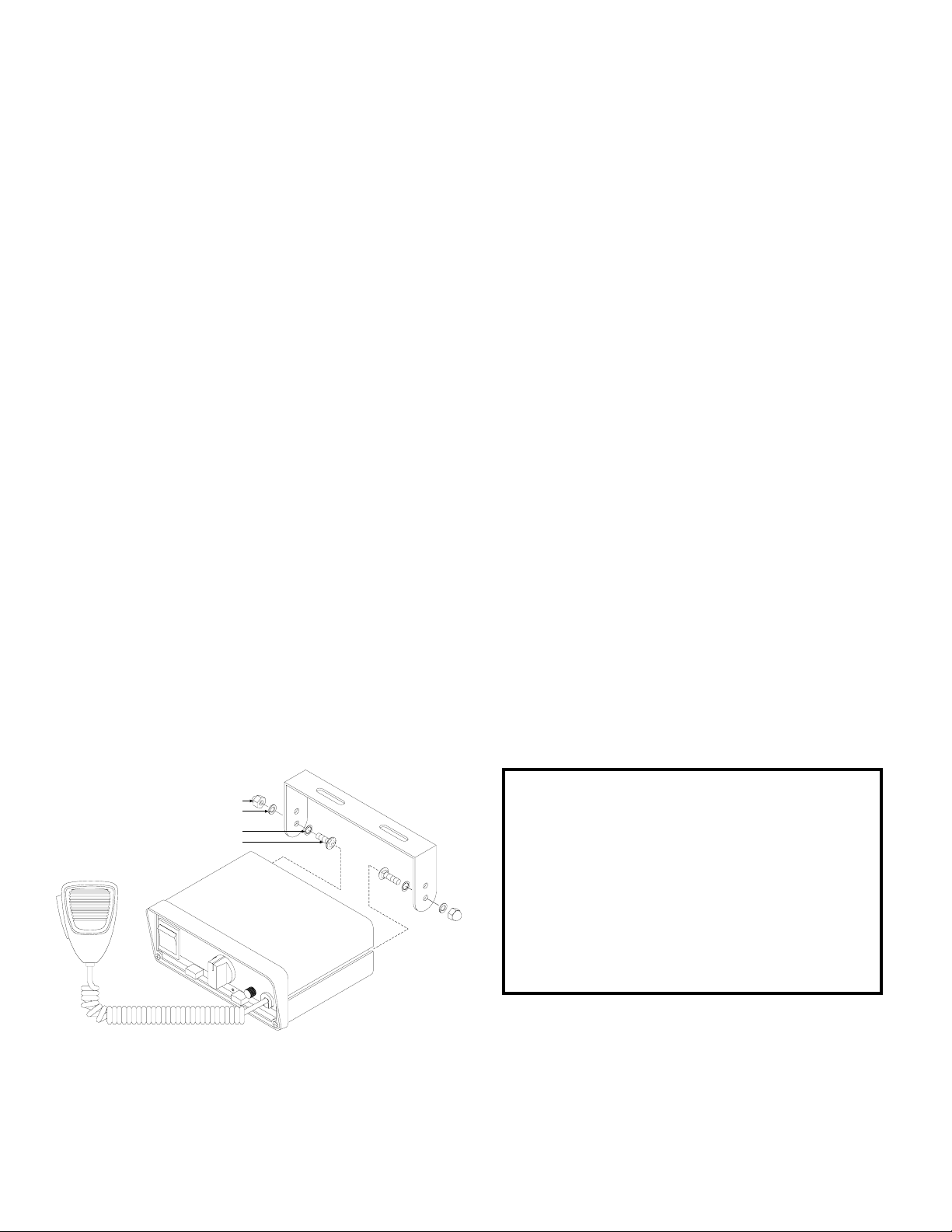
4. Secure the siren to the bail bracket using the provided
hardware as shown below.
5. Tighten the Acorn nut firmly.
Console Mount
Console manufacturers offer mounting kits that include all the
necessary hardware and brackets required to mount this unit into
their console. The console mount brackets are secured onto the
unit the same way the bail bracket is (except for the addition of
two flat washers that must be inserted between the siren and the
bracket). Please refer to the manual included with your console
for specific information on securing the siren/mounting bracket
assembly onto the console.
NOTE: Due to the lack of air flow within a console, prolonged
operation of this siren may require the console to be
modified to improve ventilation.
Microphone Clip
A microphone clip is included with this product. The installer
must refer to the Air Bag Warning below before installing this
clip.
“Acorn” Nut
Split Lock-Washer
Internal-tooth Lock-washer
Carriage Bolt
IMPORTANT AIR BAG WARNING! Do not install
this product or route any wires in the air bag
deployment zone of your vehicle. Equipment
mounted or located in air bag deployment zones will
damage or reduce the effectiv ene ss of the air bag, or
become a projectile that could cause serious
personal injury or death. Refer to your vehicle
owners manual to learn the air bag deployment
zones for the vehicle. The User/Inst a ller ass umes full
responsibility to determine proper mounting
location, based on providing ultimate safety to all
passengers inside the vehicle.
Page 2
Page 3
Wiring:
Power & Ground Wires: RED: Power / BLACK: Ground
WARNING!All customer supplied wires that connect to the positive terminal of the battery must be sized to supply at least
125% of the maximum oper ating curr ent and FUSED
THIS PRODUCT!
1. Splice the 2 RED (Power) wires together, then extend this single RED wire toward the vehicle battery. Splice the 2 BLACK
(Ground) wires together and extend this single BLACK wire toward the vehicle battery. To pass the RED and BLACK wires
through, you may have to dri ll a hole in the firewa ll. Be sure there are no componen ts th at co ul d be da ma ged . Ins ert a grommet in
the hole to protect the wires.
2. Route the R ED and BLACK wires along th e fa cto r y har nes s tow ar ds the battery and insta ll a fu se block (user sup pli ed) on the end
of the RED wire (refer to the wiring sche matic on p age 4 for y our mod el’ s fuse va lue). NOTE: Rem ove the f use from the fuse bl ock
before connecting any wires to the battery.
3. Connect the fu se b loc k wi re to the PO SIT IVE (+) te rmi nal on th e ba ttery . The r e mus t not be m ore t han 2 fee t of w ir e be tw een fuse
block and battery. The wire between the fuse and the battery is “unprotected,” don’t allow it to contact with any wires.
4. Connect the BLACK wire to the factory chassis ground.
Speaker Wires: ORANGE, YELLOW & BROWN
1. Route the ORANGE, YELLOW and BROWN wires toward the vehicle siren speakers, along the factory wire harness and through
the firewall at the same point as the RED and BLACK wires.
2. Connect the YELLOW and ORANGE wires to the POSITIVE connection on speakers #1 & 2 (respectively).
3. Connect the BROWN wire to the NEGATIVE connection on speakers #1 & 2.
Horn Relay Wires: WHITE & GREY
1. Route the WHITE and GREY wires along the factory wire harness and through the firewall at the same point as the RED and
BLACK wires.
2. Route the WHITE and GREY wires to your vehicle’s horn relay. If
possible, follow the factory wire harness to this relay.
3. Locate the wire that connects the vehicle horn to the horn relay and
cut it.
4. Connect the WHITE wire to the wire coming from the horn relay.
5. Connect the GREY wire to the wire coming from the horn.
Radio Rebroadcast (optional): 2 BLUE wires
The two remaining BLUE wires are used to connect your two-way
radio’s external speaker for radio rebroadcast (an optional connection).
NOTE: If your remote speaker is amplified (has a power amp circuit in
the speaker), radio reb road ca st w i ll not work and should n ot b e en ab led .
1. Locate the two wires that connect the external speaker to the twoway radio, cut one of them and splice one of the BLUE wires into
this circuit.
2. Now cut the remai nin g sp eak er w ire and splic e the r ema in ing BLUE
wire into this circuit.
at the battery to carry that load. DO NOT USE CIRCUIT BREAKERS WITH
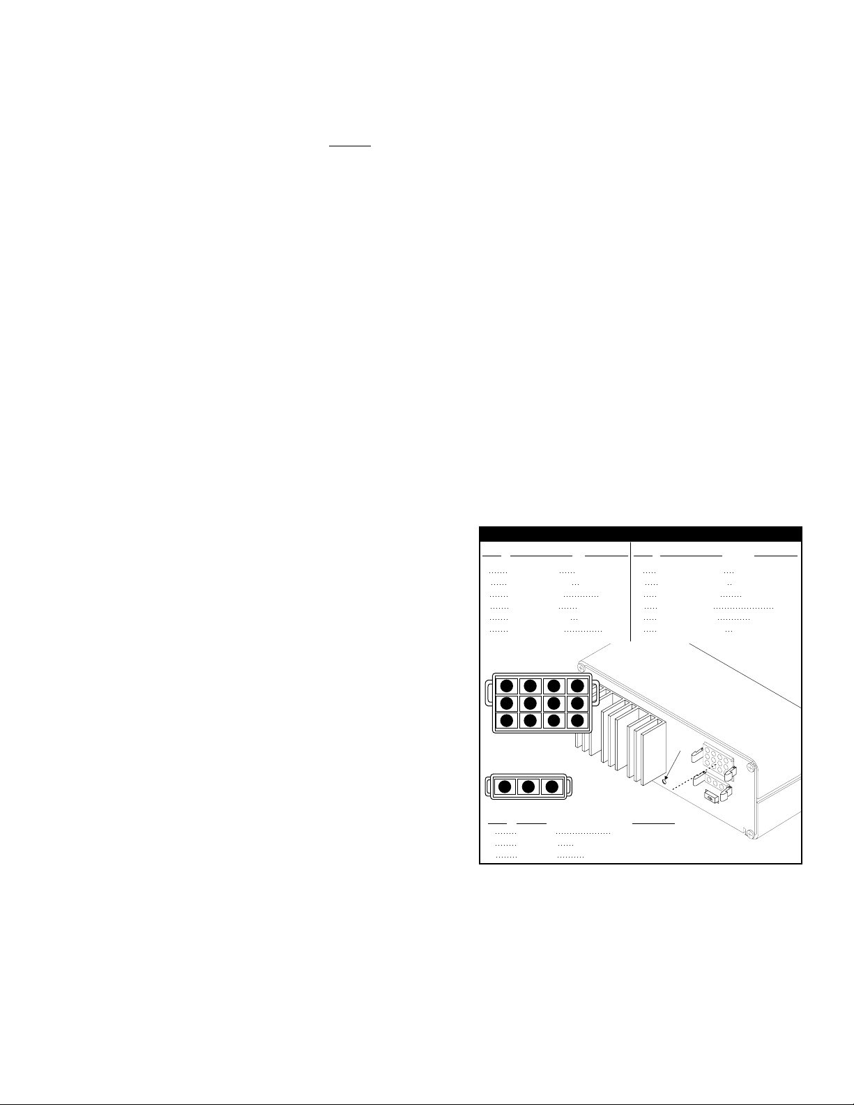
INPUT CONNECTORS
COLOR / GAGE
PIN#
1
RED 14GA/
2
BLACK / 14GA
3
BLUE / 18GA
4
RED / 14GA
5
BLACK / 14GA
6
BLUE / 18GA
INPUT CONNECTOR
(REAR VIEW)
3
6
2
5
1
4
3-POS. CONNECTOR
(REAR VIEW)
123
COLOR
PIN#
1
WHT/YEL
2
WHT/ORG
3
WHT/GRN
FUNCTION
()
+ BATTERY
(-) GROUND
RADIO
(+) BATTERY
(-) GROUND
RADIO
12
9
8711
10
BACKLIGHTING
“SIREN IN USE” OUTPUT
SIREN INTERRUPTION
PIN# FUNCTION
COLOR / GAGE
7
BROWN / 16GA
8
ORANGE / 16GA
9
VIOLET / 18GA
10
GRAY / 18GA
11
WHITE / 18GA
12
YELLOW / 16GA
FUNCTION
Scan-Lock
Switch
SPEAKER COM
SPEAKER #2 (+)
AUX. ENABLE
HORN
HORN RING
SPEAKER #1 (+)
Page 3
Page 4

Connecting to a Remote ControlHead: (Optional)
This unit may be connected to an existing
control head, such as the Whelen PCCS9NP
or equivalent. This is an optional connection
that enables the WAIL tone to be activated
through the use of a PCCS9NP button or
switch. If this connection is not chosen, cut
the VIOLET wire and cap it to prevent
accidental grounding of the wire.
All Fuses & Fuse Blocks are to
WIRING DIAGRAM
HORN
TO HORN
BUTTON
RELAY
NOTE:
be supplied by the Customer. NOT
use circuit breakers with this product!
+12V
Do
OPERATING THE CONTROLS:
Power Switch
This switch has two positions: Down (Off) and Up (On). When
this switch is Off, the unit will not function. When the switch is
On, the siren is functional and may be activated at the
operator’s discretion. This switch also activates control head
backlighting. NOTE: If the unit is connected to the vehicle’s
horn ring circuit, the vehicle horn is disabled when the power
switch is in the ON position.
MAN Button
The Manual button generates a variety of tones, depending
on what position the rotary knob is in. For further explanation
of this button’s function, refer to “Rotary Switch Operations.”
POWER
PEAKERS
12
POWER
SPEAKERS
12
MAN
MAN 1
RAD
MAN 2
MAN
RAD
MAN
12-POS.IINPUT CONNECTOR
20 AMP FUSE (12V)
10 AMP FUSE (24V)
295SLS*1 Siren
WHITE
11
GREY
10
YELLOW
12
ORANGE8
BROWN
7
BLUE
3
BLUE
6
VIOLET
9
5
BLACK
2
BLACK
RED
4
RED
1
3
WHT/GRN
WHT/ORG
2
WHT/YEL
1
CUT WIRE HERE
(TO PCDS-9 or EQUIV.)
(+)
(-)
Battery
Siren Interruption
Negative (-) Activation
To “Siren In Use” Icon
Input on Video Camera
To Dashboard
Lighting Control
Voltage
AUXILIARY
ENABLE
CONNECTION
(OPTIONAL)
CHASSIS
GROUND
VEHICLE
100W
100W
RADIO
TO 2-WAY
HORN
SPEAKER #1
SPEAKER #2
SPEAKER
T2
AD
F
MAN 1
RAD
N
T3
HORN
T1
RAD
MAN 2
MIC VOL.
T2
T3
HORN
PA Volume (MIC)
With the vehicle in an enclosed area, turn the siren on and
speak into the microphone. While speaking, turn knob
clockwise t o increase the volu me. Continue to incr ease the
PA volume until audio feedback occurs. Turn counterclockwise to eliminate feedback.
®
Horn Button
Holding the HORN button on generates a AIRHORN tone
when the siren is powered up.
MIC VOL.
Rotary Switch
HF
T1
T2
T3
RAD
The Rotary Knob controls the siren functions. There are 7
positions that may be selected. Each position and its function
is outlined under “Rotary Switch Operations.”
H
3-POS.IINPUT CONNECTOR
Page 4
Page 5

Diagnostic Indicators:
This unit has two diagnostic indicators on the front panel which
are used to indicate fa ult con dit ions with your siren syste m. Th e
following table lists the typ e of fau lt and t he i ndica tors respo nse.
If the indicator is on steady while a tone is in use, this implies
that there is no fault with the associated speaker output.
Fault Condition Diagnostic Indicators Response
Under Voltage Speaker LED #1 will be in a
DoubleFlash mode (2 quick flashes
followed by a longer pause) and the
siren tones will not operate.
Over Voltage Speaker LED #2 will be in a
DoubleFlash mode (2 quick flashes
followed by a longer pause) and the
siren tones will not operate.
Speaker #1
Short Circuit Speaker LED # 1 will be in a
SingleFlash mode (the LED will be on
and off an equal amount of time) and
the siren tones will not operate.
POWER
SPEAKERS
12
SI TEST® & Diagnostic Indicators
SI TEST
allows the operator to confirm the proper
MAN
operation of the siren speakers connected
RAD
MAN
to the unit without activating an audible
siren tone. To initiate the SI TEST® cycle,
set the rotary knob to the RAD position.
Now press and release the MAN button. As
the siren is tested, its diagnostic indicator
will turn on steady for about 1.5 seconds if
no problems are detected. If the indicator
flashes or does not light at all, a problem
with either the siren, speakers or wiring has
been detected. Check the wire connections
of the failed speaker and repeat the SI
TEST®. If the speaker fails again, have the
siren inspected by a qualified technician.
WARNING:
generating a ultra-high frequency tone
through each speaker. Although these
tones are inaudible to humans, be sure
there is nobody wit hin 5 fe et of th e spea kers
when SI TEST® is running.
® is a diagnostic feature and
Installed speak ers are t ested b y
Speaker #2
Short Circuit Speaker LED #2 will be in a
Radio Repeat Volume (RAD)
HF
2
T1
T2
T3
HORN
RAD
Locate the Radio Repeat adjustment port as
shown. Set the volume level of the vehicle’s
two-way radio to it’s normal operating
MIC
volume. Turn the Rotary Knob to RAD to
activate Radio Repeat. Insert the screwdriver
in the Radio Repeat adjustment port and turn
clockwise to increase the volume.
Speaker #1
Open Circuit Speaker LED #1 will be off (having a
SingleFlash mode (the LED will be on
and off an equal amount of time) and
the siren tones will not operate.
single speaker system will always
cause this condition for the speaker
output not in use) all tones will
continue to operate.
Speaker #2
Open Circuit Speaker LED #2 will be off (having a
single speaker system will always
cause this condition for the speaker
output not in use) all tones will
continue to operate.
Page 5
Page 6

Rotary Switch Operations
This section will outline the operation of the siren in the factory
default configuration. Refer to the Scan-L ock™ sect ion on the
following page for information and procedures on how to
customize the operation of this siren.
RAD (Radio Repeat) - When the rotary knob is in the RAD
position, any signal that is received by the vehicle’s two-way
radio will be simultaneously broadcast over the vehicle’s
loudspeaker (the unit must be connected to the tw o-way radio as
outlined in this manual).
With the Rotary Switch in this Position:
• Activating the HORN button will produce the AIRHORN tone
until released.
• Pressing the MAN button will start SI TEST® as described on
Page 5.
• Activating the HORN RING input will produce the AIRHORN
tone until the MAN switch is released.
• Activating the AUX ENABLE input has no effect.
MAN 1 (Manual Siren #1) - When the rotary switch is in this
position the si ren is in a standby st ate where no tones hav e bee n
activated, but is waiting for another action to be taken by the
operator.
With the Rotary Switch in this Position:
• Activating the HORN button will produce the AIRHORN tone
until released.
• Pressing the MAN button will produce the AIRHORN tone until
the MAN switch is released.
• Activating the HORN RING input will produce the AIRHORN
tone until the HORN RING input is released.
• Activating the AUX enable input will produce a repeating WAIL
tone.
MAN 2 (Manual Siren #2) - When the rotary switch is in this
position the siren is in a standb y state. No tones will be activated
until another action is taken by the operator.
With the Rotary Switch in this Position:
• Activating the HORN button will produce the AIRHORN tone
until released.
• Pressing the MAN switch will produce a WAIL tone. This tone
will ramp up to peak frequency and stop when the MAN switch
is released.
• Activating the HORN RING input will produce a WAIL tone. This
tone will ramp up to peak frequency and stop when the HORN
RING input is released.
• Activating the AUX enable input will produce a repeating WAIL
tone.
HF (Hands-Free Operation) - When the rotary knob is in the HF
position, the siren functions are placed in a standby mode. Siren
tones are activated by a s ing le “t ap” o n th e MAN button or on the
vehicle’s steering wheel horn ring (if the vehicle’s horn has been
wired to the HORN RING input). The first tap produces a “Wail”
tone (a steady rise and fall tone). A second tap produc es a “Yelp”
tone (a fast rise and fall to ne) . A third tap produc es a pierce r ton e
(an extremely fast rise and fall tone). The next tap returns the
siren to a wail tone and the cycle repeats itself. Two quick
successive taps will stop the siren.
With the Rotary Switch in this Position:
• Activating the HORN button will produce the AIRHORN tone
until released.
• Pressing the MAN button will produce the HF cycle as
described above.
• Activating the HORN RING input will produce the HF cycle as
described above.
• Activating the AUX ENABLE input will start the HF cycle.
Releasing the AUX ENABLE will stop the cycle.
T1 (Tone #1) - When the rotary knob is in the T1 position, a
steady, rise and fall tone (WAIL) is produced.
With the Rotary Switch in this Position:
• Activating the HORN button will produce the AIRHORN tone
until released.
• Pressing the MAN button will change the siren tone to a yelp
pattern (a fast rise and fall tone). Pressing the MAN button a
second time returns it back to WAIL.
• Activating the HORN RING input will change the siren tone to
YELP. Activating the HORN RING input again to return to a
WAIL tone.
• Activating the AUX ENABLE input has no effect.
T2 (Tone #2) - When the rotary knob is in the T2 position, a fast,
rise and fall tone (YELP) is produced.
With the Rotary Switch in this Position:
• Activating the HORN button will produce the AIRHORN tone
until released.
• Pressing the MAN button will produce the PIERCER tone.
Pressing the MAN switch a second time returns it back to
YELP.
• Activating the HORN RING input will produce the AIRHORN
tone until the HORN RING input is released.
• Activating the AUX ENABLE input has no effect.
T3 (Tone #3) - When the rotary knob is in the T3 position, an
extremely fast, rise and fall tone is produced.
With the Rotary Switch in this Position:
• Activating the HORN button will produce the AIRHORN tone
until released.
• Pressing the MAN button will result in the AIRHORN tone until
the MAN button is released.
• Pressing the HORN RING input will result in the AIRHORN tone
until the HORN RING input is released.
• Activating the AUX ENABLE will have no effect.
12-Volt Models 24-Volt Models
INPUT VOLTAGE . . . . . . . . . . . . . . . . . . . . 12 VDC ±20% 24 VDC ±20%
INPUT CURRENT. . . . . . . . . . . . . . . . . . .16 AMPS (TYP.) 8 AMPS (TYP.)
INPUT FUSE. . . . . . . . . . . . . . . . . . . . . . . . . . . . 20 AMPS 10 AMPS
SPEAKER IMPEDANCE. . . . . . . . . . . . . . .11 OHMS MIN. 11 OHMS MIN.
OPERAT ING TEMPERATURE . . . . . . .-30° C. TO +80° C. -30° C. TO +80° C.
STORAGE TEMPERATURE. . . . . . . . .-40° C. TO +70° C. -40° C. TO +70° C.
HUMIDITY. . . . . . . . . . . . . . . . . . . 99% (Non-Condensing) 99% (Non-Condensing)
Page 6
ACTIVATION OF THIS
SIREN MAY DAMAGE
UNPROTECTED EARS!
CAUTION
Loud siren noise can cause
Wear
Protection!
hearing damage and/or loss.
Refer to OSHA Section 1910.95 prior
to putting ANY siren into service!
Page 7

Scan-Lock™ Programing Procedures
With Scan-Lock, the tonal operation of the siren can be
customized to fit the users needs. A momentary switch,
accessed through a small hole on the back of the siren, is used
to change the default siren tones as outlined below. A nonconductive tool (such as the tip of a pen) should be used to
actuate this switch.
To change the primary tone for rotary switch positions T1,
T2, and T3: Put the rotary switch in the position that you wish to
change. Press and release the Scan-Lock switch. Each time the
Scan-Lock switch is pressed and released, the next available
tone will be broadcast (see “Tone List For Rotary Switch
Positions T1, T2 & T3”). When the desired tone is generated, it
will automatically be saved for that rotary switch position.
To change the override tone for rotary switch positions T1,
T2. and T3: Put the rotary switch in the position that you wish to
change. Press and ho ld the M AN b utto n on the front panel on th e
siren. Press and release the Scan-Lock switch. Each time the
Scan-Lock switch is pressed and released, the next available
tone will be broadcast (s ee “Overrid e Tone List For Rotary Switch
Positions T1, T2 & T3”). When the desired tone is present, it will
automatically be saved as the override tone for that rotary switch
position. Release the MAN button.
To change one of the tones in the hands free cycle as
described in the “Rotary Switch Operations” section of this
manual: Put the rotary switch in the HF position. Using the MAN
button on the front panel on the siren, advance to the tone that
you wish to change. Press and release the Scan-Lock switch.
Each time the Scan-Lock switch is pressed and released, the
next available tone will be broadcast (see “Tone List For Hands
Free Operation”). When the desired tone is generated, it will
automatically be saved for that hands-free cycle position.
To change the tone for rotary switch positions MAN1 or
MAN2: Put the rotary switch in the position that you wish to
change. Press and ho ld the M AN b utto n on the front panel on th e
siren. Press and release the Scan-Lock switch. Each time the
Scan-Lock switch is pressed and released, the next available
tone will be broadcast (see “Tone List For MAN1 & MAN2
Operation”). When the desired tone is generated, it will
automatically be saved for that rotary switch position. Release
the MAN button.
To change the override tone for rotary switch position RAD:
Put the rotary switch in the RAD position. Press and hold the
MAN button on the front panel on the siren. Press and release
the Scan-Lock switch. Each time the Scan-Lock switch is
pressed and released, the next available tone will be broadcast
(see “Override Tone List For RADIO Rotary Switch Position”).
When the desired tone is generated, it will automatically be
saved for that rotary switch position. Release the MAN button.
T o c hang e the tone for the HORN butto n: Put the rotary switch
in the MAN2 position. Press and hold the HORN button on the
front panel of the siren. Press and release the Scan-Lock switch.
Each time the Scan-Lock button is pressed and released, the
next available tone will be broadcast (see “Tone List for HORN
Button”). When the desired tone is generated, it is automatically
saved for HORN Button activation.
To Enable Title 13 Operat ion Mode - P lace the Rot ary Switch
into a stand-by position (MAN1, MAN2, HF) and turn the unit
OFF. While holding both the Scan-Lock™ switch and the MAN
button down, turn the unit ON. A set of Title 13-compliant tones
are now available. Note that AIRHORN is not allowed to override
the primary warning tones while in this mode.
Siren Interruption Configuration - The siren interruption
feature can be configured to operate in 2 modes:.
PAUSE: Grounding the WHT/GRN wire will deactivate the siren
and removing ground from the WHT/GRN wire will reactivate the
siren. CANCEL: (Factory default) Grounding the WHT/GRN wire
will deactivate the siren, however, removing ground from the
WHT/GRN wire will not reactivate the siren. The operator must
reset the siren by placing the rotary switch into one of the
standby positions (HF, MAN1 or MAN2).
To change the siren interruption mode - Place the rotary
switch into a standby position (HF, MAN1 or MAN2) and turn the
unit OFF. While holding both the Scan-Lock and AIRHORN
button in turn the power switch on.
To Restore the Factory Default Configuration - Place the
Rotary Switch into a stand-by position (MAN1, MAN2, HF) and
turn the unit OFF. While holding the Scan-Lock switch down, turn
the unit ON. The factory default configuration is now restored.
Tone List For Rotary Switch Positions T1, T2 & T3:
TONE OFF
WAIL*
YELP*
PIERCER
Y-249*
HI/LOW
SIMULATED
MECHANICAL
PULSED AIRHORN
AIRHORN HI/LOW
ALTERNATE WAIL*
ALTERNATE YELP*
WOOP
WARBLE
* California Title 13-Compliant Siren Tones.
Tone List For Hands Free Operation:
WAIL
YELP
PIERCER
Y-249
HI/LOW
SIMULATED
MECHANICAL
PULSED AIRHORN
AIRHORN HI/LOW
ALTERNATE WAIL
ALTERNATE YELP
WOOP
WARBLE
Tone List For HORN Button:
TONE OFF
AIRHORN COMMAND CODE
AIRHORN LOW COMMAND CODE
Page 7
Override T one List For Rotary Switch Positions T1, T2 & T3:
TONE OFF
WAIL
YELP
PIERCER
Y-249
HI/LOW
SIMULATED
MECHANICAL
PULSED AIRHORN
AIRHORN HI/LOW
ALTERNATE WAIL
ALTERNATE YELP
WOOP
WARBLE
AIRHORN
LOW FREQ. AIRHORN
Tone List For MAN1 & MAN2 Operation:
TONE OFF
MANUAL SIMULATED MECHANICAL COAST-TO-STOP
MANUAL SIMULATED MECHANICAL STOP
MANUAL WAIL COAST-TO-ST OP
MANUAL WAIL STOP
AIRHORN
LOW FREQ. AIRHORN
Override Tone List For Rotary Switch Position Radio:
TONE OFF
AIRHORN COMMAND CODE
AIRHORN LOW COMMAND
CODE
Page 8

Wire Gauge
Calculation Chart
Wire Gauge (AWG)
22
5
10
INS.
15
INS. INS.
20
INS.
25
INS.
30
INS.
35
INS.
40
INS.
45
INS.
50
INS.
55
INS.
60
INS.
65
INS.
70
INS.
75
INS.
80
INS.
85
INS.
90
INS.
95
Current Draw (AMPS)
100
INS.
6
3
INS.
INS. INS.
INS.
INS.
INS.
INS.
INS.
INS.
INS.
INS.
INS.
INS.
INS.
INS.
INS.
INS.
20
9.5
5
3
18
15
7.5
INS.
INS.
INS. INS.
INS. INS.
INS. INS.
INS. INS.
INS. INS.
INS. INS.
INS. INS. INS.
INS. INS. INS.
INS. INS. INS.
INS. INS. INS.
INS. INS. INS.
INS. INS. INS.
16
24.5
12
5
4
3
3.5
14
39
19.5
8
13
6
9.5
5
4
3
8
6.5
5.5
5
4.5
4
3.5
3
3
3
12
62
31
20.5
15.5
12.5
10.5
9
7.5
7
6
5.5
5
5
4.5
4
4
3.5
3.5
3.5
3
10
98
49
32.5
24.5
19.5
16.5
14
12.5
11
10
9
8
7.5
7
6.5
6
6
5.5
5
5
8
156
78
52
39
31
26
22.5
19.5
17.5
15.5
14
13
12
11
10.5
10
9
8.5
8
8
6
248
124
82.5
62
49.5
41.5
35.5
31
27.5
25
22.5
20.5
19
17.5
16.5
15.5
14.5
14
13
12.5
4
395
197
131
98.5
79
66
56.5
49.5
44
39.5
36
33
30.5
28
26.5
24.5
23
22
21
19.5
2
629
314
209
157
125
104
89.5
78.5
69.5
63
57
52.5
48.5
45
42
39
37
35
33
31.5
All Distances Shown Are In FeetINS. = Insufficient
To use this chart...
1. Determine the amount of current being drawn through the wire. Locate this number in the vertical left-hand
column. If the current value is between adjacent values, use the higher number.
2. Follow this row until the length of the installed wire is shown. If the exact length is between adjacent values, use
the higher number. Follow this column upwards to find the recommended size (gage) for this wire.
In the example shown below, the size for a wire with an installed length of 36 feet, through which 22 amps of current
will be drawn, must be determined.
A row for 22 amps is not shown, so the row for 25 amps will be used. Follow this row to the right. A column for 36 feet
is not shown, so the column for 49.5 feet will be used. Following this column to the top will show that the size of this
wire must be at least 6 gage.
Page 8
 Loading...