

Page 1
®
ENGINEERING COMPANY INC.
CAUTION
Loud siren noise can cause
hearing damage and/or loss.
Refer to OSHA Section 1910.95 prior
to putting ANY siren into service!
Wear
Protection!
ACTIVATION OF THIS
SIREN MAY DAMAGE
UNPROTECTED EARS!
51 Winthrop Road
Chester, Connecticut 06412-0684
Phone: (860) 526-9504
Fax: (860) 526-4078
Installation/Operating Guide:
Dual Siren Control Head & Amp
295HFSA7 Flush Mount
295HFSA8 Console Mount
Internet: www.whelen.com
Sales e-mail: autosale@whelen.com
Canadian Sales e-mail: canadiansales@whelen.com
Customer Service e-mail: custserv@whelen.com
DANGER! Sirens produce extremely loud emergency warning tones! Exposure to these tones without
proper and adequate hearing protection, could cause ear damage and/or hearing loss! The Occupational Safety &
Health Administration (www.osha.gov) provides information necessary to determine safe exposure times in
Occupational Noise Exposure Section 1910.95. Until you have determined the safe exposure times for your
specific application, operators and anyone else in the immediate vicinity should be required to wear an approved
hearing protection device. FAILURE TO FOLLOW THIS RECOMMENDATION COULD CAUSE HEARING LOSS!
Safety First
This document provides all the necessary information to allow your Whelen product to be properly and safely installed.
Before beginning the installation and/or operation of your new product, the installation technician and operator must
read this manual completely. Important information is contained herein that could prevent serious injury or damage.
• Proper installation of this product requires the installer to have a good understanding of automotive electronics,
systems and procedures.
• Failure to use specified installation parts and/or hardware will void the product warranty!
• If mounting this product requires drilling holes, the installer MUST be sure that no vehicle components or other
vital parts could be damaged by the drilling process. Check both sides of the mounting surface before drilling
begins. Also de-burr any holes and remove any metal shards or remnants. Install grommets into all wire
passage holes.
• If this manual states that this product may be mounted with suction cups, magnets, tape or Velcro®, clean the
mounting surface with a 50/50 mix of isopropyl alcohol and water and dry thoroughly.
• Do not install this product or route any wires in the deployment area of your air bag. Equipment mounted or
located in the air bag deployment area will damage or reduce the effectiveness of the air bag, or become a
projectile that could cause serious personal injury or death. Refer to your vehicle owner’s manual for the air bag
deployment area. The User/Installer assumes full responsibility to determine proper mounting location, based
on providing ultimate safety to all passengers inside the vehicle.
• For this product to operate at optimum efficiency, a good electrical connection to chassis ground must be
made. The recommended procedure requires the product ground wire to be connected directly to the NEGATIVE
(-) battery post.
• If this product uses a remote device to activate or control this product, make sure this control is located in an
area that allows both the vehicle and the control to be operated safely in any driving condition. DO NOT
ATTEMPT TO ACTIVATE OR CONTROL THIS DEVICE IN A HAZARDOUS DRIVING SITUATION.
• It is recommended that these instructions be stored in a safe place and
referred to when performing maintenance and/or reinstallation of this
product.
• FAILURE TO FOLLOW THESE SAFETY PRECAUTIONS AND
INSTRUCTIONS COULD RESULT IN DAMAGE TO THE PRODUCT OR
VEHICLE AND/OR SERIOUS INJURY TO YOU AND YOUR PASSENGERS!
Automotive: Sirens/Switches
For warranty information regarding this product, visit www.whelen.com/warranty
©2004 Whelen Engineering Company Inc.
Form No.13946G (053012)
Page 1
Page 2
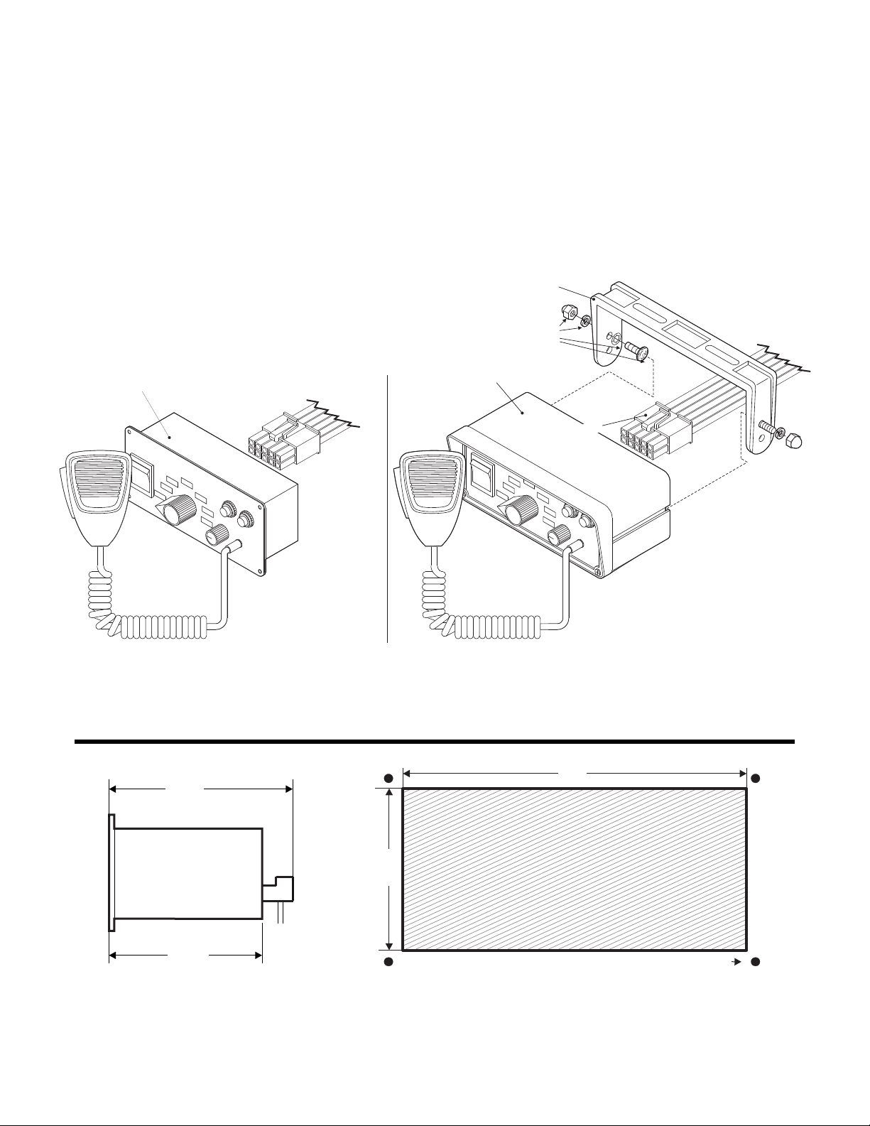
Flush Mount
Siren Input Connector
P/N 46-0746511-00
Control Head / Flush Mount
P/N 01-0269919-00
Bail Strap Mount
Installation Kit
P/N 01-0463232-00
Mounting Bracket
P/N 07-241559-000
Control Head
Console Mount
P/N 01-0269199-01
Siren Input Connector
P/N 46-0746511-00
Flush Mount: The flush mount unit can be mounted in
a console or other location. Using the measurements
below, cut the hole for the control head, then slide the
unit in. Mark and drill the four mounting holes for the
customer supplied mounting hardware.
Important: Mounting will require drilling. It is absolutely necessary
to make sure that no vehicle components behind the mounting area
will be damaged. If damage is possible, Select another location.
Installation: There are two mounting styles for the
siren control head depending on the model purchased.
Bail Strap Mount: isTh unit uses a bail strap that can
be attached under the dash. Follow the diagram above for assembly
of the bracket. You will need to supply the screws that attach the
bracket to the vehicle.
Congratulations on selecting the 295HFSA7 / 295HFSA8 Siren! This product offers a unique and distinctive collection of features designed to allow the
5.5"
Mounting Screws (Qty. 4)
2.25"
SIDE VIEW
1.35”
1.875"
1-7/8”
CUT-OUT THIS AREACUT-OUT THIS AREA
For Flush Mounting OnlyFor Flush Mounting Only
IMPORTANT: Template not to scale.
user to customize the operation of this siren to suit their individual wants or needs.
• 8 Programmable operating profiles
• Switch or ignition activated panel
illumination.
• Stereo (dual) or mono sound control.
• 200 Watts of output power.
Installation: Control Head
• Removable microphone.
• “Siren In Use” output signal.
• Hands-Free operation.
• Radio Repeat.
• Simulated mechanical siren tones.
• Harmonically-rich, composite
Airhorn tones.
• Title 13-compliant profiles.
• Independent, non-destructive short
circuit protection.
Page 2
Page 3
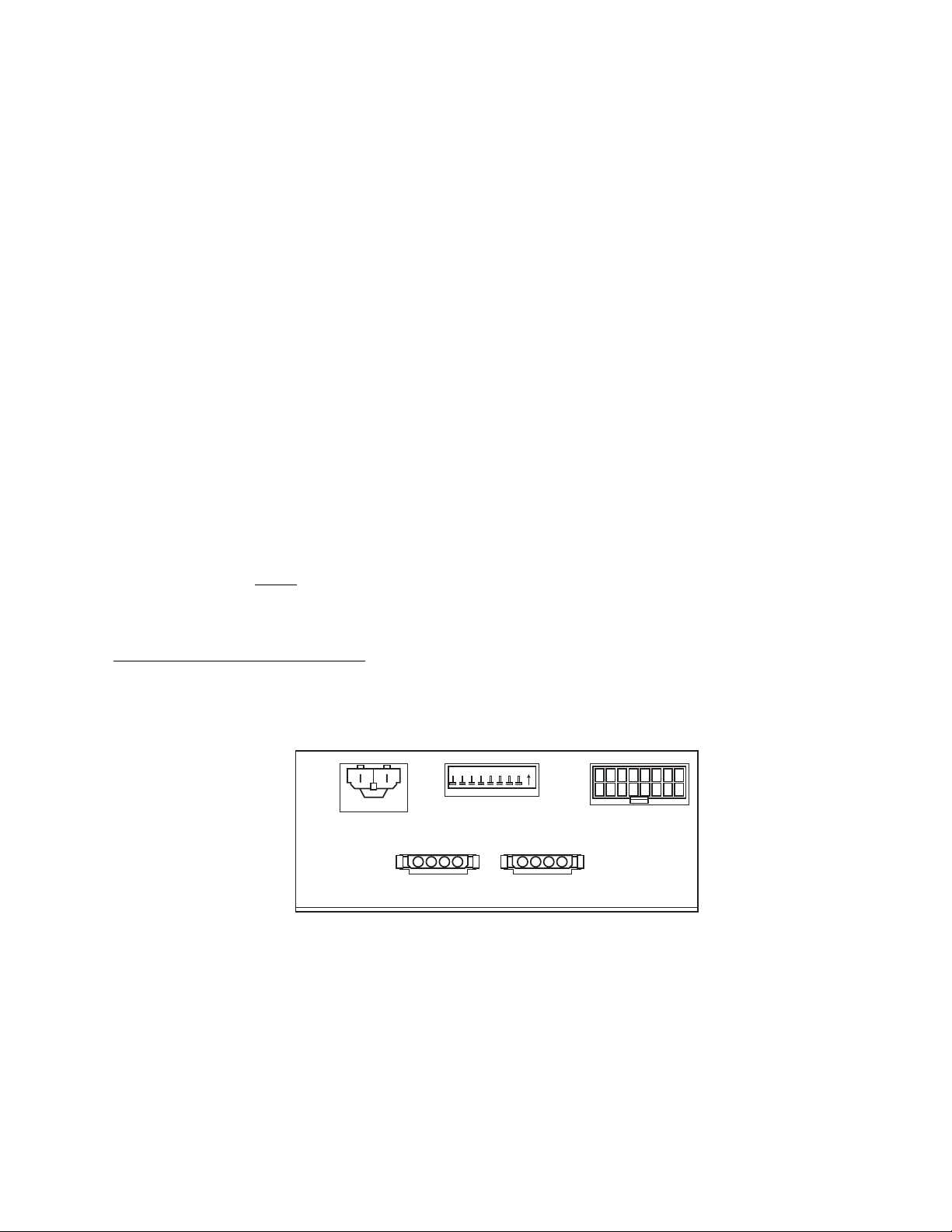
On
87654321
Main
Power
Connector
Dip
Switch
Bank
Input
Harness
Connector
Siren #1
Connector
Siren #2
Connector
Installation: Amplifier
1. Locate a suitable mounting location for the amplifier. The vertical wall
between the trunk and the passenger compartment is often a good
choice and is the method discussed in this manual.
2. Be sure that the amplifier fits properly and does not interfere with any
parts of the trunk lid or seat back.
3. Position the amplifier on the proposed mounting location. Using an
awl or other suitable tool, scribe the mounting surface where the
mounting holes are to be drilled.
CAUTION! As mounting the amplifier will require drilling, it is
absolutely necessary to make sure that no other vehicle components
could be damaged by the drilling process. If any vehicle component
could suffer any potential harm, select a different mounting location.
4. Carefully drill the mounting holes using a drill bit sized for a #10 sheet
metal screw.
5. Using the supplied #10 x 3/4” sheet metal screws, secure the remote
amplifier to the vertical trunk wall.
Wiring
Connecting to Power:
1. Using appropriately sized wire, extend the RED and BLACK wires
from the Main Power Connector, through the firewall and into the
engine compartment (refer to the Wire Gage Calculation Chart
located on the last page of this manual to determine the proper wire
size for your application).
2. Follow the factory wiring harness towards your vehicle’s battery.
WARNING! All customer supplied wires that connect to the positive
terminal of the battery must be sized to supply at least 125% of the
maximum operating current and FUSED
load. DO NOT USE CIRCUIT BREAKERS WITH THIS PRODUCT!
3. Install a user supplied 20A fuse block on the end of the RED wire.
Connect the fuse block to the battery using no more than 2 feet of
wire. Do not install the fuse into the fuse holder yet!
at the battery to carry that
4. Connect the BLACK wire directly to the NEGATIVE battery terminal.
Connecting to your Speaker(s):
1. Route the ORANGE, and BROWN wires from both Siren Connector
#1 and Siren Connector #2 along the factory wiring harness towards
your speakers.
2. Connect the ORANGE wire from Siren Connector #1 to the
POSITIVE (+) terminal on speaker #1. Connect the ORANGE wire
from Siren Connector #2 to the POSITIVE (+) terminal on speaker
#2.
3. Connect the BROWN wire from Siren Connector #1 to the
NEGATIVE (-) terminal on speaker #1. Connect the BROWN wire
from Siren Connector #2 to the NEGATIVE (-) terminal on speaker
#2.
Hands-Free Siren (optional):
Refer to the wiring diagram for all wiring information for this optional
connection.
Radio Rebroadcast (optional):
The two (2) BLUE wires are used to connect your two-way radio’s external
speaker for radio rebroadcast. This is an optional connection and will not
effect the other operations.
Note: Radio rebroadcast will NOT work with amplified remote
speakers! If your remote speaker is amplified (I.E.: contains a power
amp circuit in the speaker assembly), do not enable the radio
rebroadcast feature.
Installation will be complete after a 20A fuse has been installed in the Main
Power Connector fuse block. Now inspect the fuses at the back of the
amplifier and at the battery. If either of these fuses are blown, carefully
inspect all of the circuit wires and make sure they are wired correctly.
Replace the blown fuses with ones of an identical amp rating. If these
fuses blow after installation or activation, contact Whelen Engineering
Technical Support.
Page 3
Page 4

VEHICLE
HORN
TO
HORN
RING
CUT
X
X
3 AMP
FUSE
20 AMP
FUSE
(+)
Battery
(-)
BRN
GRY
ORG
100 WATT
SPEAKER
100 WATT
SPEAKER
ORG
ORG
BRN
BRN
TWO-WAY
RADIO SPEAKER
(Non-Amplified)
YEL
GRN
BLU
WHT/GRN*
GRN*
*see “Horn Ring
Transfer Relay
Table” for wiring
information.
BLU
BLU
On
87654321
HF
MAN
MAN
VOL
AIRHORN
STDBY
RAD
WAIL
YELP
T3
FUNCTION
MONO
DUAL
OFF
®
Horn Ring
Transfer Relay
(See table for
wiring info)
To Vehicle
Car Horn
From Vehicle
Horn Relay
To +12VDC
(Fuse @ 3A)
To +12VDC
(Fuse @ 3A)
VIO
VIO
WHT/GRN = for POS switching
GRN = for NEG switching
WHT/GRN = for POS switching
GRN = for NEG switching
30
87A
85 86
87
To Vehicle
Car Horn
N.O.
N.C.
From Vehicle
Horn Relay
Customer Supplied Horn Ring
Transfer Relay Table
Generic
Style
Bosch
Style
™
VIO
WHT/BLK
BLK/WHT
WHT
VIO
CAUTION
Loud siren noise can cause
hearing damage and/or loss.
Refer to OSHA Section 1910.95 prior
to putting ANY siren into service!
Wear
Protection!
ACTIVATION OF THIS
SIREN MAY DAMAGE
UNPROTECTED EARS!
Wiring Diagram
Page 4
Page 5

12 3
STD
RA
MONO
DUAL
OFF
HF
MAN
STDBY
RAD
WAIL
YELP
T3
FUNCTION
O
L
MAN
VOL
AIRHORN
Operating the Controls:
Power Switch (1)
This switch has three positions. Center (Off), Down (On/Mono) & Up (On/Stereo).
When this switch is Off, the unit will not function. When the switch is in either On
position, the siren is functional and may be activated at the operator’s discretion.
Rotary Knob (2)
The Rotary Knob controls the siren functions. There are 7 positions that may be
selected. Each position and its function is outlined under “Rotary Switch Operations”.
Volume Knob, Man Button and Horn Button (3)
The Volume Knob controls the volume of public address function. Volume is
increased by rotating the knob in a clockwise direction. Rotating the volume knob in a
counter-clockwise direction decreases volume. The volume knob has no effect on
any siren tones produced.
The Manual Button generates a variety of tones, depending on what position the
rotary knob is in. For further explanation of this button’s function, refer to “Rotary
Switch Operations.”
Holding the AIRHORN button on, generates an AIRHORN tone whenever the siren is
powered up.
Rotary Switch Operations:
Note: This section assumes the horn ring circuit has been wired as
shown on Page 4.
RAD (Radio Repeat) - When the rotary knob is in the RAD position, any
signal that is received by the vehicle’s two-way radio will be
simultaneously broadcast over the vehicle’s loudspeaker (unit must be
connected to the two-way radio as outlined in this manual).
With the Rotary Switch in the RAD Position:
• Activating the HORN RING will activate the VEHICLE HORN until the
HORN RING is released.
• Pressing the AIRHORN button will result in an AIRHORN tone until the
AIRHORN button is released.
• Pressing the MAN button results in the AIRHORN tone until the MAN
button is released.
STDBY (Manual Siren) - When the rotary switch is in this position the
siren is in a standby state where no tones have been activated, but is
waiting for another action to be taken by the operator. This position is often
the best choice when manual operation of the siren is desired.
With the Rotary Switch in the STDBY Position:
• Activating the HORN RING will produce a AIR HORN tone until the
HORN RING input is released.
• Pressing the AIRHORN button will result in the AIRHORN tone until the
AIRHORN button is released.
• Pressing the MAN button will result in the Manual Wail tone ramping up
to peak frequency and ramping down when the MAN button is released.
MAN (Manual Siren) - When the rotary switch is in this position the siren
is in a standby state where no tones have been activated, but is waiting for
another action to be taken by the operator. This position is used when
manual operation of the siren is desired.
With the Rotary Switch in the MAN Position:
• Activating the HORN RING will result in a Manual Wail tone ramping up
to the peak frequency and stopping when the HORN RING input is
released.
• Pressing the AIRHORN button produces an AIRHORN tone until the
AIRHORN button is released.
• Pressing the MAN button has the same effect as pressing the HORN
RING.
HF (Hands-Free Operation) - When the rotary knob is in the HF position,
the siren functions are placed in a standby mode. Siren tones are
activated by a single “tap” on the MAN button or on the vehicle’s steering
wheel horn ring (if the vehicle’s horn has been wired to the HORN RING
input). The first tap produces Wail. A second tap produces Yelp. A third tap
produces Tone 3. The next tap returns the siren to Wail and the cycle
repeats itself. Two quick successive taps will stop the siren (refer to the
tables on the following pages for hands-free tonal information).
With the Rotary Switch in the HF Position:
• Activating the HORN RING will result in the HF cycle as described
above.
• Pressing the AIRHORN button will result in the AIRHORN tone until the
AIRHORN button is released.
• Pressing the MAN button will result in the HF cycle as described above.
WAIL (Wail Tone) - When the rotary knob is in the WAIL position, a
steady, rise and fall wail tone is produced.
With the Rotary Switch in the WAIL Position:
• Activating the HORN RING will change the siren tone to the override
tone. Activating the HORN RING a second time returns it back to a
WAIL.
• Pressing the AIRHORN button will result in an AIRHORN tone until the
AIRHORN button is released.
• Pressing the MAN button will change the siren tone to the override tone.
Pressing the MAN button again returns it back to a WAIL.
YELP (Yelp Tone) - When the rotary knob is in the YELP position, a fast,
rise and fall tone is produced.
With the Rotary Switch in the YELP Position:
• Activating the HORN RING will change the siren tone to the override
tone. Activating the HORN RING a second time returns it back to a
YELP tone.
• Pressing the AIRHORN button will result in the AIRHORN tone until the
AIRHORN button is released.
• Pressing the MAN button will change the siren tone to the override tone.
Pressing the MAN button a second time returns it back to a YELP tone.
T3 (Piercer
TM
Tone (see dip switch tables)) - When the rotary knob is in
the T3 position, an extremely fast, rise and fall tone is produced.
With the Rotary Switch in the T3 Position:
• Activating the HORN RING will produce the override tone until the
HORN RING is released.
• Pressing the AIRHORN button will result in an AIRHORN tone until the
AIRHORN button is released.
• Pressing the MAN button will produce the override tone until the MAN
button is released.
Refer to the siren tables on the following pages for override tone
details.
MICROPHONE - Whenever the unit is powered on, activating the
microphone (pressing the switch on the side of the mic.) will shut down
any other siren functions & enable public address operation regardless of
the rotary switch position or any other switch or input.
Page 5
Page 6

Profile 1 - T3 = Piercer™
With the power switch in “Mono” mode, Speakers1&2
produce Speaker #1 tones simultaneously.
In “Dual” mode, Speakers1&2operate as outlined in
the following tables.
*MECH = Simulated Mechanical Tone
Note:
Profile 4 - T3 = Hi/Low
Profile 2
Profile 3
Rotary
Switch
Rotary
Switch
MAN button
Speaker #1 / Speaker #2
MAN button
Speaker #1 / Speaker #2
Operation
Speaker #1 / Speaker #2
Operation
Speaker #1 / Speaker #2
Horn Ring
Speaker #1 / Speaker #2
Horn Ring
Speaker #1 / Speaker #2
RAD
RAD
Radio / Radio
Radio / Radio
Radio / Radio
Radio / Radio
AIRHORN / AIRHORN
AIRHORN / AIRHORN
AIRHORN / AIRHORN
AIRHORN / AIRHORN AIRHORN / AIRHORN
AIRHORN / AIRHORN
AIRHORN / AIRHORN
AIRHORN / AIRHORN
STDBY
STDBY
STDBY / STDBY
STDBY / STDBY
STDBY / STDBY
STDBY / STDBY
MAN / MAN (Coast to stop)
MAN / MAN (Coast to stop)
MAN / MAN (Coast to stop)
MECH / MECH (Coast to stop) AIRHORN / AIRHORN
AIRHORN / AIRHORN
AIRHORN / AIRHORN
AIRHORN / AIRHORN
MAN
MAN
STDBY / STDBY
STDBY / STDBY
STDBY / STDBY
STDBY / STDBY
MAN / MAN (Stop)
MAN / MAN (Stop)
MAN / MAN (Stop)
MECH Coast to stop/ MECH ( ) MAN / MECH ( )Coast to stop
MAN / MAN (Stop)
MAN / MAN (Stop)
MAN / MAN (Stop)
HF
HF
STDBY / STDBY
STDBY / STDBY
STDBY / STDBY
STDBY / STDBY
WAIL / WAIL
WAIL / WAIL
WAIL / WAIL
WAIL / MECH WAIL / MECH
YELP / YELP
YELP / YELP
YELP / WAIL
YELP / MECH YELP / MECH
PIER / PIER
Hi Low Hi Low///
PIER/ YELP
PIER / MECH PIER / MECH
WAIL / WAIL
WAIL / WAIL
WAIL / WAIL
YELP / YELP
YELP / YELP
YELP / WAIL
PIER / PIER
Hi Low Hi Low///
PIER/ YELP
WAIL
WAIL
WAIL / WAIL
WAIL / WAIL
WAIL / WAIL
WAIL / MECH*
YELP / YELP
YELP / WAIL
YELP / WAIL
YELP / MECH YELP / MECH
YELP / YELP
YELP / WAIL
YELP / WAIL
YELP
YELP
YELP / YELP
YELP / YELP
YELP / WAIL
YELP / MECH
PIER / PIER
Hi Low/ / YELP
PIER/ YELP
PIER MECH/ PIER MECH/
PIER / PIER
Hi Low/ / YELP
PIER/ YELP
T3
T3
PIER / PIER
Hi Low // Hi/Low
PIER / YELP
PIER MECH/
AIRHORN / PIER
AIRHORN / Hi/Low
AIRHORN / PIER
AIRHORN / MECH AIRHORN / MECH
AIRHORN / PIER
AIRHORN / Hi/Low
AIRHORN / PIER
RAD
STDBY
MAN
HF
WAIL
YELP
T3
Rotary
Switch
MAN button
Speaker #1 / Speaker #2
Operation
Speaker #1 / Speaker #2
Horn Ring
Speaker #1 / Speaker #2
RAD
STDBY
MAN
HF
WAIL
YELP
T3
Rotary
Switch
MAN button
Speaker #1 / Speaker #2
Operation
Speaker #1 / Speaker #2
Horn Ring
Speaker #1 / Speaker #2
Dip Switch Pos:
#1 #3
OFF OFF OFF
#2
Dip Switch Pos:
#1 #3
ON ON OFF
#2
Dip Switch Pos:
#1 #3
ON OFF OFF
#2
Dip Switch Pos:
#1 #3
OFF ON OFF
#2
Page 6
Page 7

*MECH = Simulated Mechanical Tone
Profile 5 - T3 = Title 13 (Y-249)**
Profile 6 - (Title 13 / Mechanical)
Profile 7
Profile 8
Rotary
Switch
MAN button
Speaker #1 / Speaker #2
Operation
Speaker #1 / Speaker #2
Horn Ring
Speaker #1 / Speaker #2
RAD Radio / Radio
Radio / Radio
Radio / Radio
Radio / Radio
AIRHORN / AIRHORN
AIRHORN / AIRHORN
AIRHORN / AIRHORN
AIRHORN / AIRHORN
AIRHORN / AIRHORN
AIRHORN / AIRHORN
AIRHORN / AIRHORN
AIRHORN / AIRHORN
STDBY STDBY / STDBY
STDBY / STDBY
STDBY / STDBY
STDBY / STDBY
MAN / MAN (Coast to stop)
MECH / MECH (Coast to stop)
MAN / MAN (Coast to stop)
MECH / MECH (Stop)
AIRHORN / AIRHORN
AIRHORN / AIRHORN
AIRHORN / AIRHORN
AIRHORN / AIRHORN
MAN STDBY / STDBY
STDBY / STDBY
STDBY / STDBY
STDBY / STDBY
MAN / MAN (Stop)
MAN / MECH (Stop)
MAN / MAN (Stop)
MECH / MECH (Coast to stop)
MAN / MECH (Stop)
MAN / MAN (Stop)
MECH / MECH (Coast to stop)
MAN / MAN (Stop)
HF STDBY / STDBY
STDBY / STDBY
STDBY / STDBY
STDBY / STDBY
WAIL / WAIL
WAIL / MECH
Whoop / Whoop
MECH / MECH
WAIL / MECH
Whoop / Whoop
MECH / MECH
YELP / YELP
YELP / MECH
Warble / Warble
YELP / MECH
PIER / MECH PIER / MECH
YELP / MECH
Warble / Warble
YELP / MECH
WAIL / WAIL
YELP / YELP
WAIL WAIL / WAIL
WAIL / MECH*
Warble / Warble
MECH / MECH
YELP / WAIL
YELP / MECH
Whoop / Warble
WAIL / MECH
YELP / MECH
Whoop / Warble
WAIL / MECH
YELP / WAIL
YELP YELP / YELP
YELP / MECH
Whoop / Whoop
YELP / MECH
Y-249 / YELP
Y-249 / MECH
MECH / Whoop
PIER/ MECH
Y-249 / MECH
MECH / Whoop
PIER / MECH
Y-249 / YELP
** a tone designed for compliance
with California Title 13
T3 Y-249 Y-249/
Y-249 / MECH
MECH / MECH
PIER / MECH
YELP Y-249/
Y-249 / MECH
AIRHORN / MECH
AIRHORN / PIER
AIRHORN / AIRHORN
AIRHORN / MECH
AIRHORN / PIER
YELP Y-249/
RAD
STDBY
MAN
HF
WAIL
YELP
T3
Rotary
Switch
MAN button
Speaker #1 / Speaker #2
Operation
Speaker #1 / Speaker #2
Horn Ring
Speaker #1 / Speaker #2
RAD
STDBY
MAN
HF
WAIL
YELP
T3
Rotary
Switch
MAN button
Speaker #1 / Speaker #2
Operation
Speaker #1 / Speaker #2
Horn Ring
Speaker #1 / Speaker #2
RAD
STDBY
MAN
HF
WAIL
YELP
T3
Rotary
Switch
MAN button
Speaker #1 / Speaker #2
Operation
Speaker #1 / Speaker #2
Horn Ring
Speaker #1 / Speaker #2
Dip Switch Pos:
#1 #3
OFF OFF ON
#2
Dip Switch Pos:
#1 #3
ON OFF ON
#2
Dip Switch Pos:
#1 #3
OFF ON ON
#2
Dip Switch Pos:
#1 #3
ON ON ON
#2
Page 7
Page 8

Current Draw (AMPS)
Wire Gauge
Calculation Chart
All Distances Shown Are In FeetINS. = Insufficient
5
22
6
3
INS.
INS. INS.
INS.
INS. INS.
INS.
INS.
INS. INS.
INS. INS.
INS. INS.
INS. INS.
INS. INS.
INS. INS.
INS. INS. INS.
INS. INS. INS.
INS. INS. INS.
INS. INS. INS.
INS. INS. INS.
INS. INS. INS.
INS.
INS.
INS.
INS.
INS.
INS.
INS.
INS.
INS.
INS.
INS.
INS.
INS.
INS.
INS.
INS.
INS.
INS.
INS.
INS.
INS.
INS.
INS.
INS.
INS.
INS.
INS.
INS.
INS.
INS.
20
9.5
5
3
18
15
7.5
5
4
3
16
24.5
12
8
6
5
4
3.5
3
14
39
19.5
13
9.5
8
6.5
5.5
5
4.5
4
3.5
3
3
3
12
62
31
20.5
15.5
12.5
10.5
9
7.5
7
6
5.5
5
5
4.5
4
4
3.5
3.5
3.5
3
10
98
49
32.5
24.5
19.5
16.5
14
12.5
11
10
9
8
7.5
7
6.5
6
6
5.5
5
5
8
156
78
52
39
31
26
22.5
19.5
17.5
15.5
14
13
12
11
10.5
10
9
8.5
8
8
6
248
124
82.5
62
49.5
41.5
35.5
31
27.5
25
22.5
20.5
19
17.5
16.5
15.5
14.5
14
13
12.5
4
395
197
131
98.5
79
66
56.5
49.5
44
39.5
36
33
30.5
28
26.5
24.5
23
22
21
19.5
2
629
314
209
157
125
104
89.5
78.5
69.5
63
57
52.5
48.5
45
42
39
37
35
33
31.5
10
15
20
25
30
35
40
45
50
55
60
65
70
75
80
85
90
95
100
Wire Gauge (AWG)
To use this chart...
1. Determine the amount of current being drawn through the wire. Locate this number in the vertical left-hand
column. If the current value is between adjacent values, use the higher number.
2. Follow this row until the length of the installed wire is shown. If the exact length is between adjacent values, use
the higher number. Follow this column upwards to find the recommended size (gage) for this wire.
In the example shown below, the size for a wire with an installed length of 36 feet, through which 22 amps of current
will be drawn, must be determined.
A row for 22 amps is not shown, so the row for 25 amps will be used. Follow this row to the right. A column for 36 feet
is not shown, so the column for 49.5 feet will be used. Following this column to the top will show that the size of this
wire must be at least 6 gage.
Page 8
 Loading...