

Page 1
®
ENGINEERING COMPANY INC.
51 Winthrop Road
Chester, Connecticut 06412-0684
Phone: (860) 526-9504
Fax: (860) 526-4078
Siren/Power Control Center
Installation Guide:
Model(s) 295HFSA5
295HFSM5
Internet: www.whelen.com
Sales e-mail: autosale@whelen.com
Canadian Sales e-mail: autocan@whelen.com
Customer Service e-mail: custserv@whelen.com
DANGER! Sirens produces extremely loud emergency warning tones! Exposure to these
tones without proper and adequate hearing protection, could cause ear damage and/or hearing
loss! The Occupational Safety & Health Administration (www.osha.gov) provides information
necessary to determine safe exposure times in Occupational Noise Exposure Section 1910.95.
Until you have determined the safe exposure times for your specific application, operators and
anyone else in the immediate vicinity should be required to wear an approved hearing protection
device. FAILURE TO FOLLOW THIS RECOMMENDATION COULD CAUSE HEARING LOSS!
Safety First
This document provides all the necessary information to allow your Whelen product to be properly and safely installed.
Before beginning the installation and/or operation of your new product, the installation technician and operator must
read this manual completely. Important information is contained herein that could prevent serious injury or damage.
• Proper installation of this product requires the installer to have a good understanding of automotive electronics,
systems and procedures.
• If mounting this product requires drilling holes, the installer MUST be sure that no vehicle components or other
vital parts could be damaged by the drilling process. Check both sides of the mounting surface before drilling
begins. Also de-burr any holes and remove any metal shards or remnants. Install grommets into all wire
passage holes.
• If this manual states that this product may be mounted with suction cups, magnets, tape or Velcro®, clean the
mounting surface with a 50/50 mix of isopropyl alcohol and water and dry thoroughly.
• Do not install this product or route any wires in the deployment area of your air bag. Equipment mounted or
located in the air bag deployment area will damage or reduce the effectiveness of the air bag, or become a
projectile that could cause serious personal injury or death. Refer to your vehicle owner’s manual for the air bag
deployment area. The User/Installer assumes full responsibility to determine proper mounting location, based
on providing ultimate safety to all passengers inside the vehicle.
• For this product to operate at optimum efficiency, a good electrical connection to chassis ground must be
made. The recommended procedure requires the product ground wire to be connected directly to the NEGATIVE
(-) battery post.
• If this product uses a remote device to activate or control this product, make sure this control is located in an
area that allows both the vehicle and the control to be operated safely in any driving condition. DO NOT
ATTEMPT TO ACTIVATE OR CONTROL THIS DEVICE IN A HAZARDOUS DRIVING SITUATION.
• It is recommended that these instructions be stored in a safe place and
referred to when performing maintenance and/or reinstallation of this
product.
• FAILURE TO FOLLOW THESE SAFETY PRECAUTIONS AND
INSTRUCTIONS COULD RESULT IN DAMAGE TO THE PRODUCT OR
VEHICLE AND/OR SERIOUS INJURY TO YOU AND YOUR PASSENGERS!
ACTIVATION OF THIS
SIREN MAY DAMAGE
UNPROTECTED EARS!
CAUTION
Loud siren noise can cause
hearing damage and/or loss.
Wear
Refer to OSHA Section 1910.95 prior
Protection!
to putting ANY siren into service!
Automotive: Sirens/Switches
For warranty information regarding this product, visit www.whelen.com/warranty
©2000 Whelen Engineering Company Inc.
Form No.13491K (050208)
Page 1
Page 2

WARNING!
DISCONNECTING THE VEHICLE BRAKE LAMP
CIRCUIT USING ANY SIRENS WITH RELAY OUTPUTS
OR SWITCH CONTROLLERS COULD CAUSE
VEHICLE OR PROPERTY DAMAGE, SERIOUS INJURY
OR EVEN DEATH.
DISABLING THIS CIRCUIT IS A VIOLATION OF THE
FEDERAL MOTOR VEHICLE SAFETY STANDARD
FOR THE THIRD BRAKE LIGHT, AS WELL AS REAR
BRAKE LIGHTS.
FUNCTIONS THAT BLACK OUT THE REAR BRAKE
LIGHTS (SOMETIMES CALLED “BRAKE LIGHT CUT
OUT”) MAY INTERFERE WITH THE BRAKE SHIFT
LOCK MECHANISM, AND CAUSE THE VEHICLE TO
MOVE UNEXPECTEDLY AND DANGEROUSLY.
DISCONNECTING THE BRAKE LIGHTS IN ANY WAY
IS AT YOUR OWN
RISK AND IS NOT RECOMMENDED
BY WHELEN.
Page 2
Page 3
READ BEFORE INSTALLING!!!
Do not install this product or route any wires in the deployment
area of your air bag. Equipment mounted or located in
the air bag deployment area will damage or reduce the
effectiveness of the air bag or become a projectile that could
cause serious personal injury or death. Refer to your vehicle
owner's manual for the air bag deployment area.
The User/Installer assumes full responsibility to determine the
proper mounting location, based on providing ultimate safety
to all passengers inside the vehicle. Whelen Engineering Co.
assumes no liability or responsibility for determining individual
applications or exact installation location criteria.
Mounting:
An aftermarket center console is recommended for the mounting
location. If console mounting is not possible, the unit includes a bail
strap mounting kit for over or under dash mounting.
Wiring the 295HFS_5 (refer to wiring diagram on pg. 6):
WARNING: All customer supplied wires that connect to the
positive terminal of the battery must be sized to supply at
least 125% of the maximum operating current and FUSED at
the battery to carry that load. DO NOT USE CIRCUIT
BREAKERS WITH THIS PRODUCT! (see customer wire chart)
Power Wires
1. Insert the Siren Input Connector (P4) into its port.
2. Splice the 2 RED wires together, then extend this single RED
wire to the battery. Install a 20 amp fuse block (customer
supplied) to the end of the wire and connect it to the POSITIVE
(+) terminal on the battery (remove the fuse before connecting
any wires to the battery).
IMPORTANT: There must not be more than 2 feet of wire between the fuse
block and the battery. The wire between the fuse and the battery is
“unprotected.” Do not allow this wire to come in contact with other wires.
1. Route and connect the GREEN wire to the desired lightbar
function control wire(s).
2. Route and connect the GREY wire to the desired lightbar
function control wire(s).
3. Route and connect the BLUE wire to the desired lightbar
function control wire(s).
Horn Relay Wires / White & Grey Wires
1. Run the WHITE and GREY wires to the vehicle’s horn relay. If
possible, follow the factory wire harness.
2. Cut the wire that connects the vehicle horn to the horn relay.
3. Connect WHITE wire to wire coming from horn relay.
4. Connect GREY wire to wire coming from horn.
Radio Rebroadcast / Blue Wires (Optional)
Radio rebroadcast will NOT work with amplified speakers. If your
remote speaker contains a power amp in the speaker, do not
enable the radio re-roadcast feature.
1. Locate the two wires that connect the external speaker to the
vehicle’s two-way radio.
2. Cut one of these wires and splice one of the BLUE wires into
this circuit.
3. Cut the remaining speaker wire and splice the remaining
BLUE wire into this circuit.
Siren Shut-Down / Violet Wire (Optional)
The 295HFSA5 can be configured to cease all automatic siren
tones whenever the VIOLET wire from P4 is grounded through a
switch. If this is not desired, cut and cap the VIOLET wire.
Backlighting
3. Splice the 2 BLACK wires together and connect them to the
negative terminal of the battery.
4. Run the RED wire from Output P1 to the battery and connect it
to a 3 Amp fuse block, (customer supplied) then to the positive
terminal of the battery.
Speaker Wires / Yellow, Orange & Brown Wires
This section outlines a two-speaker installation. If using one
speaker, cut and cap the ORANGE wire, and skip steps 3 & 4.
1. Run the YELLOW, ORANGE and BROWN wires to the vehicle
siren speakers.
2. SPEAKER 1 -YELLOW to POSITIVE speaker connection and
BROWN to the NEGATIVE speaker connection.
3. SPEAKER 2 - ORANGE to POSITIVE speaker connection.
4. Splice a wire from the NEGATIVE connection on SPEAKER 1
to the NEGATIVE connection on SPEAKER 2.
Slide Switch Control Wires / Green, Grey & Blue
NOTE: The push-button and slide switch control wires are
designed to activate relays with a coil rating nogreater than 250
ma. Do not connect them to any circuit rated higher.
When the power switch is on, the HFSA5’s backlighting is on.
When the power switch is off, backlighting can be turned on by
connecting the WHITE / RED wire from P2 to a +12VDC source
that is activated with the vehicle’s ignition switch.
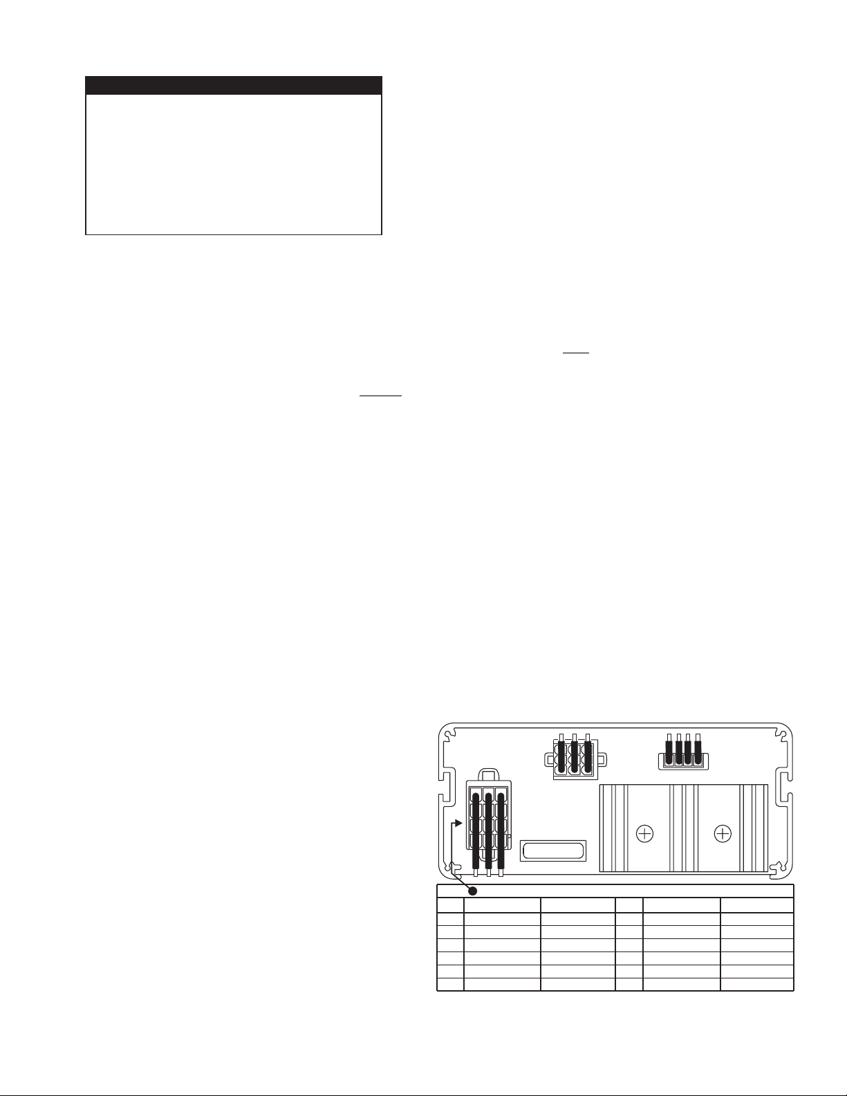
REAR VIEW
P1
P2
1
P4
20 AMP FUSE
12 POSITION SIREN INPUT CONNECTOR
COLOR & GAGE
PIN #
RED 14GA
1
BLACK 14GA
2
BLUE 18GA
3
RED 14GA
4
BLACK 14GA
5
BLUE 18GA
6
FUNCTION
+ BATTERY
GROUND
RADIO
+ BATTERY
GROUND
RADIO
COLOR & GAGE
PIN #
BROWN 16GA
7
ORANGE 16GA
8
VIOLET 18GA
9
GRAY 18GA
10
WHITE 18GA
11
YELLOW 16GA
12
FUNCTION
SPEAKER COM
+SPEAKER #2
REMOTE ACT.
HORN
HORN/RING
+SPEAKER #1
Page 3
Page 4

Configuring the Slide Switch Functions:
In the default dip switch setting, the P1 outputs are:
Slide Switch Positions: Push-Buttons:
0 = Terminals OFF 4 = White / Black
1 = Green 5 = White
2 = Green / Grey 6 = Yellow
3 = Green / Grey / Blue 7 = Orange
8 = Black / White
9 = Violet
Changing Default Slide Switch Control:
= OFF
87654321
=ON
1 - Slide Switch Output 1 (GRN)
2 - Slide Switch Output 2 (GRY)
3 - Slide Switch Output 3 (BLU)
4 - Switch 4 Output (WHT/BLK)
5 - Switch 5 Output (WHT)
6 - Switch 6 Output (YEL)
7 - Switch 7 Output (ORN)
8 - Switch 8 Output (BLK/WHT)
Dip Switch
Dip Switch
Bank 4
Bank 1
Dip Switch
Bank 2
Dip Switch
Bank 3
Configuring Slide Switch Control:
The slide switch has four positions: 0 (off), 1, 2 & 3. When in position 0 (furthest to the left) the slide switch has not activated
any outputs. In position 1, 2 or 3 the slide switch can activate any combination of outputs 1 through 8. Each active slide
switch position uses a bank of dip switches to determine which outputs are to be active while the slide switch is in that
position; position 1 uses dip switch bank 1, position 2 uses dip switch bank 2, and position 3 uses dip switch bank 3.
Each dip switch bank is comprised of 8 switches, each representing a corresponding output (switch 1 for output 1, switch 2
for output 2, etc.). If, for example, switches 1, 3, 4 & 6 on dip switch bank 1 are in the ON position, outputs 1, 3, 4 & 6 will be
active when the slide switch is moved to position 1.
Slide switch configuration is as simple as deciding which outputs are to be active in a given position and then moving the
corresponding dip switch on the appropriate dip switch bank to the ON position.
Page 4
Page 5

Custom Dip Switch Configuration (Dip Switch Bank 4):
Push-button 9 (momentary switch) can function in 4 different modes, defined by the 4-position dip switch bank 4.
This bank is located on top of the circuit board and is only accessible with the cover removed from the PCCS9NP.
Mode 1 - (default) - In this configuration, the output is activated for as long as push-button 9 is depressed.
Mode 2 - In this configuration, when push-button 9 is pressed, the output is activated for a period of 8 seconds.
Mode 3 - In this configuration, when push-button 9 is pressed, the output is activated. When pressed again, the
output is deactivated.
Mode 4 - In this configuration, when push-button 9 is pressed, the output is activated for a period of 400 ms. After
400 ms, the output is deactivated for 400 ms. This cycle will continue until push-button 9 is pressed again.
Enabling siren tones through slide switch pos. #3:
Slide switch position 3 can be configured to
automatically activate siren tones, as described in
“Rotary Switch Operations” (pg.6). If this is not desired,
make sure that dip switch #1 on bank 4 is in the off
position (the factory default position). Please note that
siren activation through slide switch position 3 is only
available when the power switch is in the ON position.
BANK 4 , -POSITIONDIP SWITCH CHART 4
Default (factory) setting shown.
Switch 9
(momentary)
1
ON
OFF
SWITCH 9 CAN TO OPERATE IN 4 DIFFERENT MODES,
DEFINED BY THE 4 POSITION DIP SWITCH :- (Bank 4)
MODE 1 (DEFAULT)
1 2 3 4
ON
offoff off off
OFF
PANEL SWITCH 9
OPERATING MODE:
MOMENTARY
Down
(OFF)
MODE 2
1 2 3 4
offoff off
PANEL SWITCH 9
OPERATING MODE:
8 SECOND ON TIMER
23 4
Down
(OFF)
on
OPERATING MODE:
Down
(OFF)
MODE 3
1 2 3 4
on
offoff off
PANEL SWITCH 9
LATCH ON
LATCH OFF
OPERATING MODE:
(400MS ON & OFF)
Down
(OFF)
MODE 4
1 2 3 4
on
offoff off
PANEL SWITCH 9
FLASHER
Page 5
Page 6

WIRING DIAGRAM
REMOTE
ACTIVATION
BACKLGHTING
SWITCH 8
OUTPUT
WHITE / RED
RED - see note 1
1
WHITE / GREEN
2
P2
OUTPUTS
BLACK / WHITE
WHT/BLK - SW#4 OUTPUT
ORN - SW#7 OUTPUT
YEL - SW#6 OUTPUT
WHT - SW#5 OUTPUT
GRY - SLIDE SW#2 OUTPUT
BLU - SLIDE SW#3 OUTPUT
VIO - HI/LOW CONTROL (EDGE ONLY)
3
4
987621
5
34
P1
GRN - SLIDE SW#1 OUTPUT
BRN - see note 2
295HFS_5
SIREN INPUT CONNECTOR
RED
RED
RED
FUSE
CUSTOMER
3 AMP
SUPPLIED
FUSE
CUSTOMER
20 AMP
SUPPLIED
BLACK
SIREN SHUTDOWN
12V BATTERY
Note 1 - This RED wire provides power to the push-buttons.
Fuse @ 3 amps and connect to switched +12VDC.
Note 2 - This BROWN wire provides power to the slide switch.
Fuse @ 3 amps and connect to +12VDC.
P4
941526378121011
BLUE
BLUE
BLACK
BLACK
VIOLET
BROWN
BLUE
BLUE
BROWN
ORANGE
SPKR.
#2
TO TWO WAY-
RADIO SPEAKER
11 OHM
11 OHM
ORANGE
SPKR.
#1
GREY
WHITE
YELLOW
YELLOW
VEHICLE
HORN
TO HORN
BUTTON
RELAY
CUT
WIRE
HORN
+12V
SPECIFICATIONS
INPUT VOLTAGE. . . . . . . . . . . . . . . . . . . . . 12.5 VDC ±20%
INPUT CURRENT @15 VDC @ 5.5 OHMS . 16 AMPS MAX.
INPUT FUSE . . . . . . . . . . . . . . . . . . . . . . . . . . . . . . 20 AMPS
SPEAKER IMPEDANCE . . . . . . . . . . . . . . . .5.5 OHMS MIN.
OPERATING TEMPERATURE . . . . . . . . -30° C. TO +60° C.
STORAGE TEMPERATURE . . . . . . . . . . -40° C. TO +70° C.
HUMIDITY . . . . . . . . . . . . . . . . . 99% (NON CONDENSING)
OUTPUT VOLTAGE @ 15 VDC @ 11 OHMS 32 V RMS MAX.
OUTPUT POWER@ 15 VDC @ 11 OHMS 105 WATTS MAX.
DIAGNOSTIC INDICATORS
There are has two diagnostic indicators on the front panel which
are used to indicate fault conditions with your siren system. The
following table lists the type of fault and the indicators response.
If the indicator is on steady while a tone is in use, this implies
that there is no fault with the associated speaker output.
Fault Condition and Diagnostic Indicator Response:
Under Voltage Speaker LED #2 will be in a double flash
mode (2 quick flashes followed by a longer pause) and the
siren tones will not operate.
Over Voltage Speaker LED #1 will be in a double flash
mode (2 quick flashes followed by a longer pause) and the
siren tones will not operate.
Speaker #1 Short Circuit Speaker LED # 1 will be in a sin-
gle flash mode (the LED will be on and off an equal amount
of time) and the siren tones will not operate.
Speaker #2 Short Circuit Speaker LED #2 will be in a sin-
gle flash mode (the LED will be on and off an equal amount
of time) and the siren tones will not operate.
Speaker #1 (Not Connected) Speaker LED #1 will be off,
all tones will continue to operate.
Speaker #2 (Not Connected) Speaker LED #2 will be off,
all tones will continue to operate.
RECOMENDED SIZE for CUSTOMER SUPPLIED WIRES:
Switch Power
18 AWG..............................................................13 FT. MAX
16 AWG..............................................................21 FT. MAX
Siren Power & Ground
12 AWG..............................................................18 FT. MAX
10 AWG..............................................................30 FT. MAX
Rotary Switch Operations:
RAD (Radio Repeat) - When the rotary knob is in the RAD
position, any signal that is received by the vehicle’s two-way
radio will be simultaneously broadcast over the vehicle’s
loudspeaker (unit must be connected to the two-way radio as
outlined in this manual).
With the Rotary Switch in this Position:
• Pressing the MAN switch will result in SI TEST® (see SI TEST
section)
• Pressing the HORN switch will result in the AIRHORN tone until
the HORN switch is released.
• Activating the HORN RING input results in the AIRHORN tone
until the HORN RING input is released.
• Activating the SIREN SHUTDOWN input has no effect.
• Activating the AUX ENABLE input has no effect.
OUTPUT POWER@ 15 VDC @ 5.5 OHMS 185 WATTS MAX.
Page 6
Page 7

PA (Public Address) - When the rotary switch is in this position the
siren is in a standby state where no tones have been activated, but is
waiting for another action to be taken by the operator. The best choice
when public address is required.
With the Rotary Switch in this Position:
• Pressing the MAN switch will result in a WAIL tone ramping up to
the peak frequency and ramping down to a stop at the lowest
frequency when the MAN switch is released (model 295HFSM5
produces mechanical wail).
• Pressing the HORN switch will result in the AIRHORN tone until
the HORN switch is released.
• Activating the HORN RING input will result in the AIRHORN tone
until the HORN RING input is released (model 295HFSM5
produces mechanical wail).
• Activating the SIREN SHUTDOWN input has no effect (model
295HFSM5 will initiate ‘Siren Brake’).
• Activating the AUX ENABLE (or slide switch position 3, if selected)
input will result in a repeating WAIL tone.
MAN (Manual Siren) - When the rotary switch is in this position the
siren is in a standby state where no tones have been activated, but is
waiting for another action to be taken by the operator. This position is
often the best choice when manual operation of the siren is desired.
With the Rotary Switch in this Position:
• Pressing the MAN switch will result in a WAIL tone ramping up to
peak frequency and stopping when the MAN switch is released.
• Pressing the HORN switch will result in the AIRHORN tone until
the HORN switch is released.
• Activating the HORN RING input will result in a WAIL tone ramping
up to the peek frequency and stopping when the HORN RING
switch is released.
• Activating the SIREN SHUTDOWN input has no effect.
• Activating the AUX ENABLE input (Or slide switch position 3, if
selected) will result in a repeating WAIL tone.
HF (Hands Free Operation) - When the rotary knob is in the HF
position, siren functions are placed in a stand-by mode. Siren tones are
activated by a single “tap” on the MAN button or on the vehicle’s
steering wheel horn ring (if the vehicle’s horn has been wired to the
HORN RING input). The first tap produces a Wail tone (a steady rise
and fall tone). A second tap produces a Yelp tone (a fast rise and fall
tone.) A third tap produces a Piercer™ tone (an extremely fast rise and
fall tone). The next tap returns the siren to a wail tone and the cycle
repeats itself. Two quick successive taps will stop the siren.
With the Rotary Switch in this Position:
• Pressing the MAN switch will result in the HF cycle as described
above.
• Pressing the HORN switch will result in the AIRHORN tone until
the HORN switch is released.
• Activating the HORN RING input will result in the HF cycle as
described above.
• Activating the SIREN SHUTDOWN input will shut the WAIL, YELP
and PIERCER tones down. However the HORN and the HORN
RING switch will activate an AIRHORN tone and the MAN switch
will activate a momentary WAIL tone.
• Activating the AUX ENABLE input (or slide switch position 3, if
selected) will start the HF cycle.
WAIL (Wail Tone) - When the rotary knob is in the WAIL position, a
steady, rise and fall tone (Wail) is produced.
With the Rotary Switch in this Position:
• Pressing the MAN switch will change the siren tone to a yelp
pattern. (a fast rise and fall tone).
• Pressing the MAN switch a second time returns it back to a Wail
tone.
• Pressing the HORN switch will result in the Airhorn tone until the
HORN switch is released.
• Activating the HORN RING input will change the siren tone to a
Yelp pattern (a fast rise and fall tone).
• Activating the HORN RING input a second time returns it back to a
Wail tone.
• Activating the SIREN SHUTDOWN input will shut the Wail, Yelp
tones down. However the HORN and the HORN RING switch will
activate an Airhorn tone, and the MAN switch will activate a
momentary Wail tone.
• Activating the AUX ENABLE input has no effect.
YELP (Yelp Tone) - When the rotary knob is in the YELP position, a
fast, rise and fall tone is produced.
With the Rotary Switch in this Position:
• Pressing the MAN switch will change the siren tone to a Piercer
pattern (an extremely fast rise and fall tone).
• Pressing the MAN switch a second time returns it back to a Yelp
tone.
• Pressing the HORN switch will result in the Airhorn tone until the
HORN switch is released.
• Activating the HORN RING input will change the siren tone to a
Piercer tone. Activating the HORN RING input a second time
returns it back to a Yelp tone.
• Activating the SIREN SHUTDOWN input will shut the Yelp and
Piercer tones down. However the HORN RING switch will activate
an Airhorn tone and the MAN switch will activate a momentary
Wail tone.
• Activating the AUX ENABLE input has no effect.
T3 (Piercer™ Tone) - When the rotary knob is in the T3 position, an
extremely fast, rise and fall tone is produced. May be used for HI/LOW
and mechanical wail in some applications.
With the Rotary Switch in this Position:
• Pressing the MAN switch will result in the Airhorn tone until the
MAN switch is released.
• Pressing the horn switch will result in the Airhorn tone until the
HORN switch is released.
• Activating the HORN RING input will result in the Airhorn tone until
the man switch is released.
• Activating the PARK SHUTDOWN input will shut the Piercer tone
down. However the HORN and the HORN RING switch will
activate an Airhorn tone, and the MAN switch will activate a
momentary Wail tone (model 295HFSM5 will initiate ‘Siren Brake’).
• Activating the AUX ENABLE will have no effect.
Microphone
Whenever the power is on, activating the microphone (pressing the
switch on the side of the mic.) will shut down any other siren functions
and enable public address operation regardless of the rotary switch
position or any other switch or input.
Page 7
Page 8

Siren Operations:
MA
PA
RAD
PWR
RAD
POWER SWITCH
This switch has two positions: Down / Off
and Up / On. When this switch is Off, the
unit will not function. When the switch is
On, the siren is functional and may be
activated at the operator’s discretion.
NOTE: If this unit is connected to the
vehicle’s horn ring circuit, the vehicle horn
is disabled when the power switch is in
the ON position.
YELP
T3
MAN
HORN
MAN BUTTON
The Manual button generates a variety of
tones, depending on what position the
rotary knob is in. For further explanation
of this button’s function, refer to Rotary
Switch Operations.
MAN
PA
RAD
RAD
MAN
HORN
AKERS
2
PWR
HF WAIL
MAN
PA
RAD
RAD
YELP
T3
ROTARY SWITCH
The Rotary Knob control siren and PA
(Public Address) functions. There are 7
positions that may be selected. Each
position and it’s function is outlined under
“Rotary Switch Operations”.
VOLUME KNOB
The Volume Knob controls the volume of
Public Address function. Volume is
increased by rotating the knob in a
clockwise direction. Rotating the volume
knob in a counter-clockwise direction
decreases the volume produced by these
features. The volume knob has no effect
on any siren tones produced.
RADIO REPEAT VOLUME
Before use, the Radio Repeat output
volume must be adjusted to satisfactory
operating levels. To adjust this level, a
small, flat-blade screwdriver needed.
Locate the Radio Repeat adjustment port
(potentiometer) to the right of the Rotary
Knob on the face of the control head. Set
the volume level of the vehicle’s two-way
radio to its normal operating volume. Turn
the Rotary Knob on the control head to
RAD to activate Radio Repeat. Insert the
screwdriver in the Radio Repeat
adjustment port and turn in clockwise
direction to increase the sound level.
ELP
T3
YELP
T3
HORN
21
SPEAKERS
21
SPEAKERS
MAN
HORN
SI TEST® & DIAGNOSTIC
INDICATORS
SI TEST is a diagnostic feature that
allows the operator to confirm the proper
operation of the siren speakers
connected to the unit without activating
an audible siren tone. To initiate SI TEST
cycle, set the rotary knob to the RAD
position. Now press and release the
MAN button. As the siren is tested, its
diagnostic indicator will turn on steady for
about 1.5 seconds if no problems are
detected. If the indicator flashes, or does
not light at all, a problem with either the
siren, speakers, or wiring has been
detected. Check the wire connections of
the failed speaker and repeat the SI
TEST. If the speaker fails to test again,
have the siren itself inspected by a
qualified technician. NOTE: Installed
speakers are tested by generating an
ultra-high frequency tone through each
speaker. Although these tones are
inaudible to humans, be sure that there is
nobody within 5 feet of the speakers
when SI TEST
is running.
HORN BUTTON
Holding the HORN button on, generates
an AIRHORN tone whenever the siren is
powered up.
Page 8
 Loading...