

Page 1
273 Branchport Avenue
Long Branch, N.J. 07740
(732) 222-6880
INSTALLATION INSTRUCTIONS
TALKBACK HORN SYSTEM
MODEL NUMBER: TBH-104
APPLICATION INFORMATION:
WARNING: ANY MATERIAL EXTRAPOLATED FROM THIS DOCUMENT OR FROM WHEELOCK MANUALS OR OTHER DOCUMENTS
DESCRIBING THE PRODUCT FOR USE IN PROMOTIONAL OR ADVERTISING CLAIMS, OR FOR ANY OTHER USE, INCLUDING DESCRIPTION
OF THE PRODUCT'S APPLICATION, OPERATION, INSTALLATION AND TESTING IS USED AT THE SOLE RISK OF THE USER AND WHEELOCK
WILL NOT HAVE ANY LIABILITY FOR SUCH USE.
The TBH-104 is a two component talkback system which consists of a control unit and an 8 ohm horn, both of which are designed for indoor or outdoor
use. An optional S-H8 8 ohm horn may be added to the TBH-104 system when 2 horns are required. The control unit contains an omni-directional
microphone and a preamplifier for talkback. It also contains a 4 watt amplifier to power the horn which is used for one-way voice paging, background
music and tone alerting. The TBH-104 is compatible with most EKSU, KSU (1A2) and PABX systems. The TBH-104 may be used in single zone or
multi-zone applications. For typical connection applications for the TBH-104, See Figure 2.
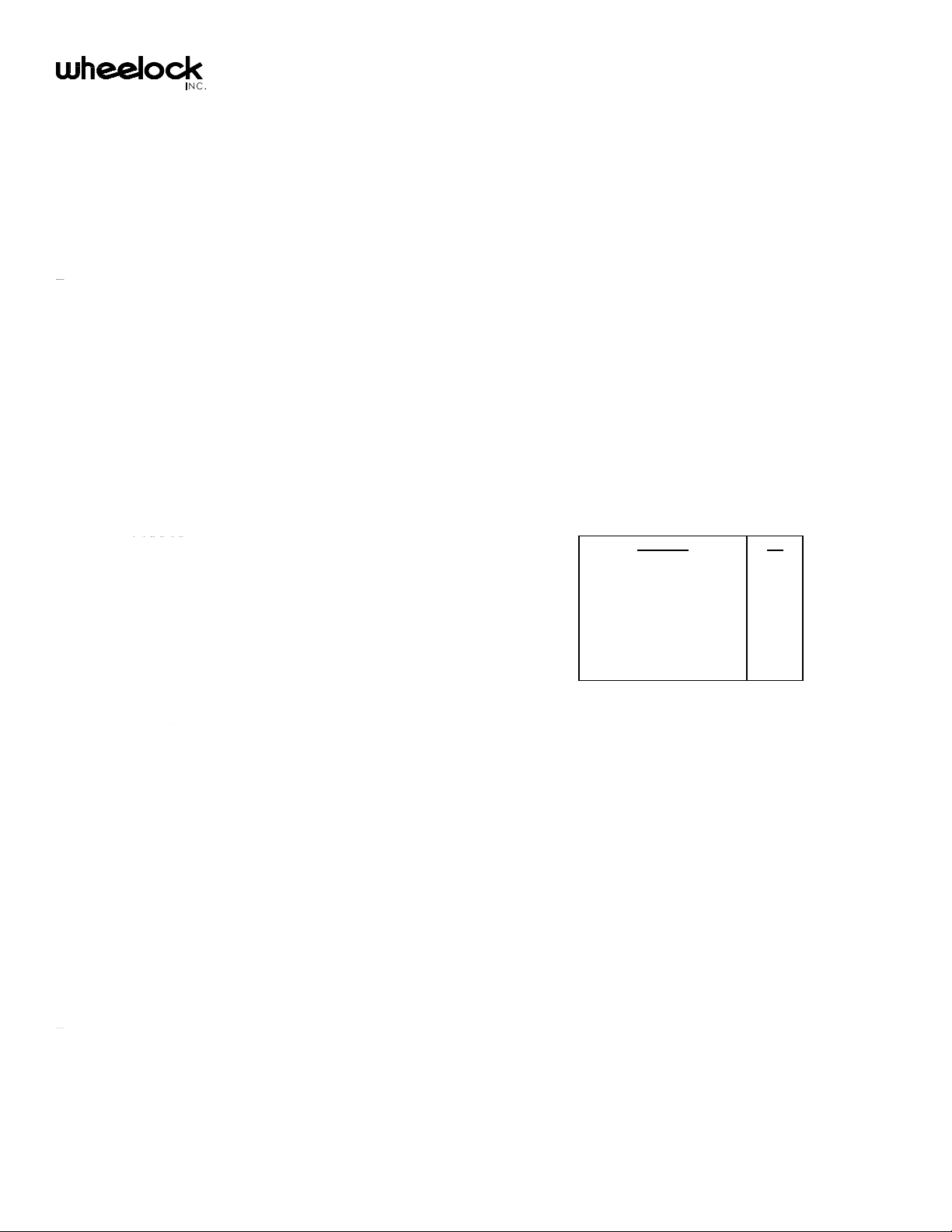
The 4 watt voice paging capability of the TBH-104 is ideal for use in noisy environments or for large areas. The talkback capability of the TBH-104 will
effectively service up to 1000 square feet, depending upon the background noise level. See Figure 1 and Chart 1 for relation between noise and
maximum reply distance. The direction of speech is controlled by the calling party (at the telephone), to prevent false switching of speech direction due
to background noise.
Machine Shop
Manufacturing (Noisy)
Printing Shop
Assembly Line
Supermarket
Transportation Waiting Room
Office (Noisy)
Shipping/Warehouse
Location
dB
90
80
80
75
75
75
70
70
Figure 1: Talkback Distance Vs. Ambient Noise Chart 1: Typical Noise Levels
Figure 2: Talkback/Paging Connections & Applications Figure 2A: Optional S-H8 Second Horn Connection
CAUTION: These devices are not intended for use in hazardous locations as defined by the National Electrical Code (NEC) and by the National
Fire Protection Association (NFPA).
Copyright 1988, 1989, 1990, 1991, 1993, 1994 Wheelock, Inc. All rights reserved.
P81752 G
Sheet 1 of 4
NOTES:
Page 2
1. Wheelock's TBH-104 Talkback Horn may be connected to a 600 ohm low power audio page port, if the page port allows two-way audio. Check with
telephone system manufacturer.
2. If unused CO port requires talk battery to pass audio (most do), then install using a Wheelock RPS-2406 power supply as shown in
Figure 4A. For multi-zone applications, a Wheelock Zone Control is required as an interface.
3. "INH" is used only when TBH-104 is connected to a Wheelock Zone Control. The "INH" wire inhibits (disconnects) talkback when an all zone page is
initiated. Use adjacent "GND" wire only when TBH-104 and Zone Control are using separate power supplies. When not connected to a Zone
Control, install a jumper between adjacent "GND" and "INH" terminals.
PRIVACY LED INDICATOR OPERATION:
A. When connected to a Wheelock Zone control Module:
- The privacy LED illuminates only when the TBH-104 is in the talkback mode.
B. When connected directly to an unused CO port:
- The LED will be illuminated when the TBH-104 is in the idle state. Occasional flicker of the LED is normal (caused by sudden noise).
- When in the two-way communication (hands free talkback) mode, the privacy LED will be illuminated only when in the talkback mode.
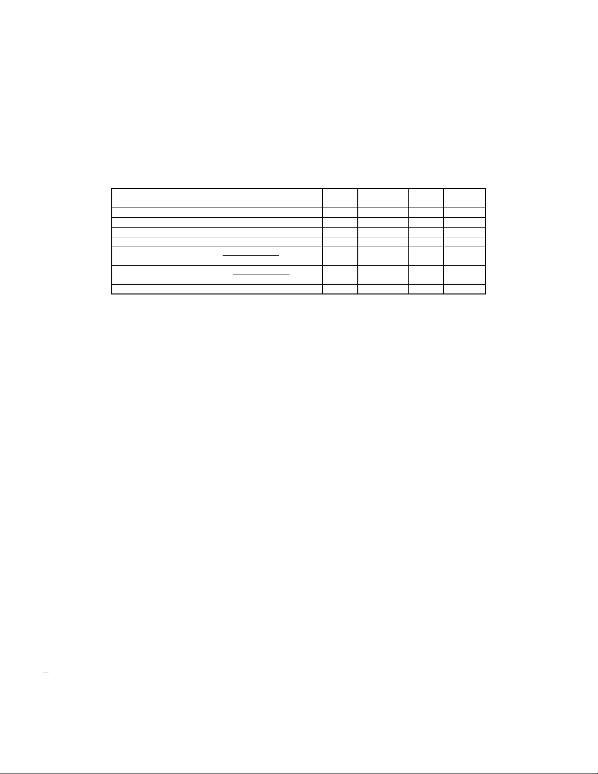
SPECIFICATIONS:
INSTALLATION INFORMATION:
The TBH-104 has been designed as a two component system to allow each component to be located so the optimum effectiveness of each can be
obtained. The system should not be located near noise producing equipment such as machinery, fans, air conditioners, etc. The TBH-104 Horn should
be positioned in a location that will project the paging output toward the area to be covered. The horn should be mounted at least 15 feet above floor
level. The TBH-104 Control Unit should be located in an area with the least amount of ambient noise and the most convenient place for people to reply
to the page. Refer to Figure 1 and Chart 1 for suggested reply distances at a given ambient noise level. Ideal mounting height for the control unit is 6 to
12 feet above floor level.
When installing the TBH-104, be sure to use mounting hardware suitable for the surface to which the components are to be mounted. To install the
Control Unit, simply mount one screw in desired location for top (key hole) tab of control unit. Place key-hole tab over the screw. Secure the control unit
by mounting a second screw through the clearance hole of the bottom tab, spacing the 2 mounting screws vertically on 10.250" centers (See Figure 3).
The horn may be surface mounted by simply using the holes in the swivel base to locate and drill mounting holes. The mounting base is also fully
adjustable in both the vertical and horizontal planes.
To rotate horn into desired position; first loosen wing nuts located on the base of horn, position horn as desired, then re tighten wing nuts to maintain
selected position. See Figure 4.
Parameter Min. Nom. Max. Units
Supply Voltage -20 -24 -28 VDC
Operating Current --- 250 400 mA
Audio Input Level -15 --- 10 dBm
T & R Input Impedance --- 600 --- Ohms
Switching Speed --- 200 --- m Sec
Audio Output Level @ 1 Meter One 8 ohm horn --- 115 --- dB
Two 8 ohm horns * --- 110 (Each) --- dB
Output Power One 8 ohm horn --- 4 --- Watts
Two 8 ohm horns * --- 1.5 (each) --- Watts
Talkback Reply Distance @ 50dB Ambient --- 50 --- Ft.
* When 2 horns are used, they must be connected in series as shown in Figure 2A.
Figure 3: Control Unit Mounting Figure 4: Horn Mounting
CAUTION: Must be mounted as shown with keyhole tab at top.
CONNECTION DIRECTLY TO AN UNUSED CO PORT:
When connecting a TBH-104 directly to an unused CO port requiring talk battery to pass audio (most do), install with a Wheelock RPS-2406 power
supply as shown in Figure 4A.
P81752 G
Sheet 2 of 4
Page 3

Figure 4A: Unused Co Port Installation
WIRING INFORMATION:
The TBH-104 control unit is provided with 4 knockouts to accommodate 1/2 inch conduit for installation purposes. When mounting the TBH-104
outdoors, a 1/2 inch conduit with rain tight fittings must be used to prevent damage to the unit due to water.
Follow the procedure below, and refer to Figure 5, when wiring to the TBH-104:
- Make sure the 24VDC Power Supply is disconnected from 115VAC Power Source.
- Remove cover of control unit by removing the 2 holddown screws; 4 more holddown screws are contained in a plastic bag within the enclosure.
- Connect 24VDC power supply "+" and "-" to Control Unit "GND" and "-24" terminals, respectively.
- Connect audio (Tip and Ring) from telephone system, or Wheelock Zone Control Modules to Control Units "TIP" and "RNG" terminals, respectively
- For connection to an unused CO port requiring talk battery, install as shown in Figure 4A.
- When used with Wheelock's Zone Control Modules:
(A) Connect the Control Units terminal labeled "INH" to the Zone Control Modules "INH" terminal.
(B) If Control Unit and Zone Control Module use separate power supplies, then also connect the adjacent
terminal labeled "GND" to the Zone Controls "GND" terminal.
- When not used with Wheelock Zone Control, install jumper between adjacent terminals "INH" and "GND".
- Connect the white wire from the horn to the terminal "H+".
- Connect the white/red wire from the horn to the terminal "H-".
(For optional second horn, refer to Figure 2A for wiring connections to horns.)
- Make sure wires do not rest against black heat sink on circuit board.
- Recheck all wiring.
- Connect the power supply to 115VAC power source.
OPERATING INSTRUCTIONS:
- Pick up telephone hand set and press the CO line button, or dial the number assigned to paging. When used with Wheelock Zone Control, next
touch/dial single digit number assigned to zone in which TBH-104 has been connected, and listen for page alert tone.
- Paging and talkback is now possible. The calling party has control of the conversation (direction of speech).
- Talkback is possible only while LED is illuminated and calling party is silent.
- Talkback (respond hands free) at a voice level normally used (in that location) to respond to another person at the same distance.
- Adjust the "HORN VOL" (PAGE) control and "MIC VOL" (TALKBACK) control located on the printed circuit board to desired levels See
Figure 5.
- Replace cover on control unit and tighten sufficiently to ensure a watertight seal with the gasket.
P81752 G
Sheet 3 of 4
Page 4

Figure 5: Simplified Schematic & Wiring Diagram
If Zone Control is not used, then install jumper between adjacent terminals "INH" and "GND".
NOTE:
TROUBLING SHOOTING:
CONDITION CHECK
1. No sound in page mode. 1) Check that horn volume control is turned up (clockwise).
2) Check presence and polarity of -24VDC and GND.
3) Check audio presence and level on TIP and RING at TBH-104 Control Unit , and if
necessary also at the audio source. (-15dBM is minimum audio level required)
2. Low volume in page mode. 1) Check that "HORN VOL" (PAGE) control in Control Unit is turned up (clockwise).
2) Check audio presence and level on TIP and RING at Control Unit, and if necessary
also at the audio source. (-15dBM is minimum audio level required).
3. Listening volume at phone is too high or
too low in talkback mode.
1) Set the "MIC VOL" (TALKBACK) control to the suitable listening level.
NOTE: Some telephone systems require that CO trunk port (loop start) or CO line port be equipped with a trunk card, page card or other equipment.
Consult the telephone manufactures system manual for equipment or programming required.
Limited Warranty
Wheelock products must be used within their published specifications and must be PROPERLY specified, applied, installed, operated, maintained and operationally tested in
accordance with these instructions at the time of installation and at least twice a year or more often and in accordance with local, state and federal codes, regulations and
laws. Specification, application, installation, operation, maintenance and testing must be performed by qualified personnel for proper operation in accordance with all of the
latest National Fire Protection Association (NFPA), Underwriters' Laboratories (UL), National Electrical Code (NEC), Occupational Safety and Health Administration (OSHA),
local, state, county, province, district, federal and other applicable building and fire standards, guidelines, regulations, laws and codes including, but not limited to, all
appendices and amendments and the requirements of the local authority having jurisdiction (AHJ). Wheelock products when properly specified, applied, installed, operated,
maintained and operationally tested as provided above are warranted against mechanical and electrical defects for a period of one year from date of installation or 18 months
from date of manufacture (as determined by date code), whichever first occurs. Correction of defects by repair or replacement shall be at Wheelock's sole discretion and
shall constitute fulfillment of all obligations under this warranty. THE FOREGOING LIMITED WARRANTY SHALL IMMEDIATELY TERMINATE IN THE EVENT ANY PART
NOT FURNISHED BY WHEELOCK IS INSTALLED IN THE PRODUCT. THE FOREGOING LIMITED WARRANTY SPECIFICALLY EXCLUDES ANY SOFTWARE
REQUIRED FOR THE OPERATION OF OR INCLUDED IN A PRODUCT. WHEELOCK MAKES NO REPRESENTATION OR WARRANTY OF ANY OTHER KIND,
EXPRESS, IMPLIED OR STATUTORY WHETHER AS TO MERCHANTABILITY, FITNESS FOR A PARTICULAR PURPOSE OR ANY OTHER MATTER.
USERS ARE SOLELY RESPONSIBLE FOR DETERMINING WHETHER A PRODUCT IS SUITABLE FOR THE USER'S PURPOSES, OR WHETHER IT WILL ACHIEVE
THE USER'S INTENDED RESULTS. THERE IS NO WARRANTY AGAINST DAMAGE RESULTING FROM MISAPPLICATION, IMPROPER SPECIFICATION, ABUSE,
ACCIDENT OR OTHER OPERATING CONDITIONS BEYOND WHEELOCK'S CONTROL.
WHEELOCK DOES NOT WARRANT THAT THE OPERATION OF THE SOFTWARE WILL BE UNINTERRUPTED OR ERROR-FREE OR THAT THE SOFTWARE WILL
MEET ANY OTHER STANDARD OF PERFORMANCE, OR THAT THE FUNCTIONS OR PERFORMANCE OF THE SOFTWARE WILL MEET THE USER'S
REQUIREMENTS. WHEELOCK SHALL NOT BE LIABLE FOR ANY DELAYS, BREAKDOWNS, INTERRUPTIONS, LOSS, DESTRUCTION, ALTERATION, OR OTHER
PROBLEMS IN THE USE OF A PRODUCT ARISING OUT OF OR CAUSED BY THE SOFTWARE.
THE LIABILITY OF WHEELOCK ARISING OUT OF THE SUPPLYING OF A PRODUCT, OR ITS USE, WHETHER ON WARRANTIES, NEGLIGENCE, OR OTHERWISE,
SHALL NOT IN ANY CASE EXCEED THE COST OF CORRECTING DEFECTS AS STATED IN THE LIMITED WARRANTY AND UPON EXPIRATION OF THE WARRANTY
PERIOD ALL SUCH LIABILITY SHALL TERMINATE. WHEELOCK IS NOT LIABLE FOR LABOR COSTS INCURRED IN REMOVAL, REINSTALLATION OR REPAIR OF
THE PRODUCT BY ANYONE OTHER THAN WHEELOCK OR FOR DAMAGE OF ANY TYPE WHATSOEVER, INCLUDING BUT NOT LIMITED TO, LOSS OF PROFIT OR
INCIDENTAL OR CONSEQUENTIAL DAMAGES. THE FOREGOING SHALL CONSTITUTE THE SOLE REMEDY OF THE PURCHASER AND THE EXCLUSIVE LIABILITY
OF WHEELOCK.
IN NO CASE WILL WHEELOCK'S LIABILITY EXCEED THE PURCHASE PRICE PAID FOR A PRODUCT.
Limitation of Liability
WHEELOCK'S LIABILITY ON ANY CLAIM OF ANY KIND, INCLUDING NEGLIGENCE AND BREACH OF WARRANTY, FOR ANY LOSS OR DAMAGE RESULTING FROM,
ARISING OUT OF, OR CONNECTED WITH THIS CONTRACT, OR FROM THE MANUFACTURE, SALE, DELIVERY, RESALE, REPAIR OR USE OF ANY PRODUCT
COVERED BY THIS ORDER SHALL BE LIMITED TO THE PRICE APPLICABLE TO THE PRODUCT OR PART THEREOF WHICH GIVES RISE TO THE CLAIM.
WHEELOCK'S LIABILITY ON ANY CLAIM OF ANY KIND SHALL CEASE IMMEDIATELY UPON THE INSTALLATION IN THE PRODUCT OF ANY PART NOT FURNISHED
BY WHEELOCK. IN NO EVENT SHALL WHEELOCK BE LIABLE FOR ANY CLAIM OF ANY KIND UNLESS IT IS PROVEN THAT OUR PRODUCT WAS A DIRECT
CAUSE OF SUCH CLAIM. FURTHER, IN NO EVENT, INCLUDING IN THE CASE OF A CLAIM OF NEGLIGENCE, SHALL WHEELOCK BE LIABLE FOR INCIDENTAL OR
CONSEQUENTIAL DAMAGES. SOME STATES DO NOT ALLOW THE EXCLUSION OR LIMITATION OF INCIDENTAL OR CONSEQUENTIAL DAMAGES, SO THE
PRECEDING LIMITATION MAY NOT APPLY TO ALL PURCHASERS.
1/94
P81752 G
Sheet 4 of 4
 Loading...