

Page 1
FIRE ALARM SYSTEMS
Description:
Wheelock’s Series MT and MT Strobe Multitone electronic
appliances offer a choice of eight (8) nationally and
internationally recognized alerting sounds: Horn, Bell,
March Time Horn, Code-3 Tone, Code-3 Horn, Slow
Whoop, Siren or Hi/Lo Tone. With MT and MT Strobe
appliances, one alarm appliance meets most of your
signaling needs. Strobe models can be synchronized
using the Wheelock SM or DSM sync modules.
Each MT and MT Strobe appliance has two installer
selective sound output levels: STANDARD dBA and
HIGH dBA. Non-strobe versions provide selectable
voltage capability in one unit, 12VDC or 24VDC, filtered
or FWR. Strobe versions are specific for either 12VDC
or 24VDC and may be used with filtered or unfiltered
(full-wave-rectified) input voltages. Separate input
terminals are available, shunt wires are provided to
enable both tone and strobe to operate simultaneously
from a single input.
The Multitone Strobe appliances are ULC Listed under
Standard CAN/ULC-S526-02 for Visual Signaling
Appliances and Standard CAN/ULC-S525-99 for Audible
Signal Appliances, and use a Xenon flashtube with solid
state circuitry enclosed in a rugged Lexan ® lens to
provide maximum reliability for effective visible signaling.
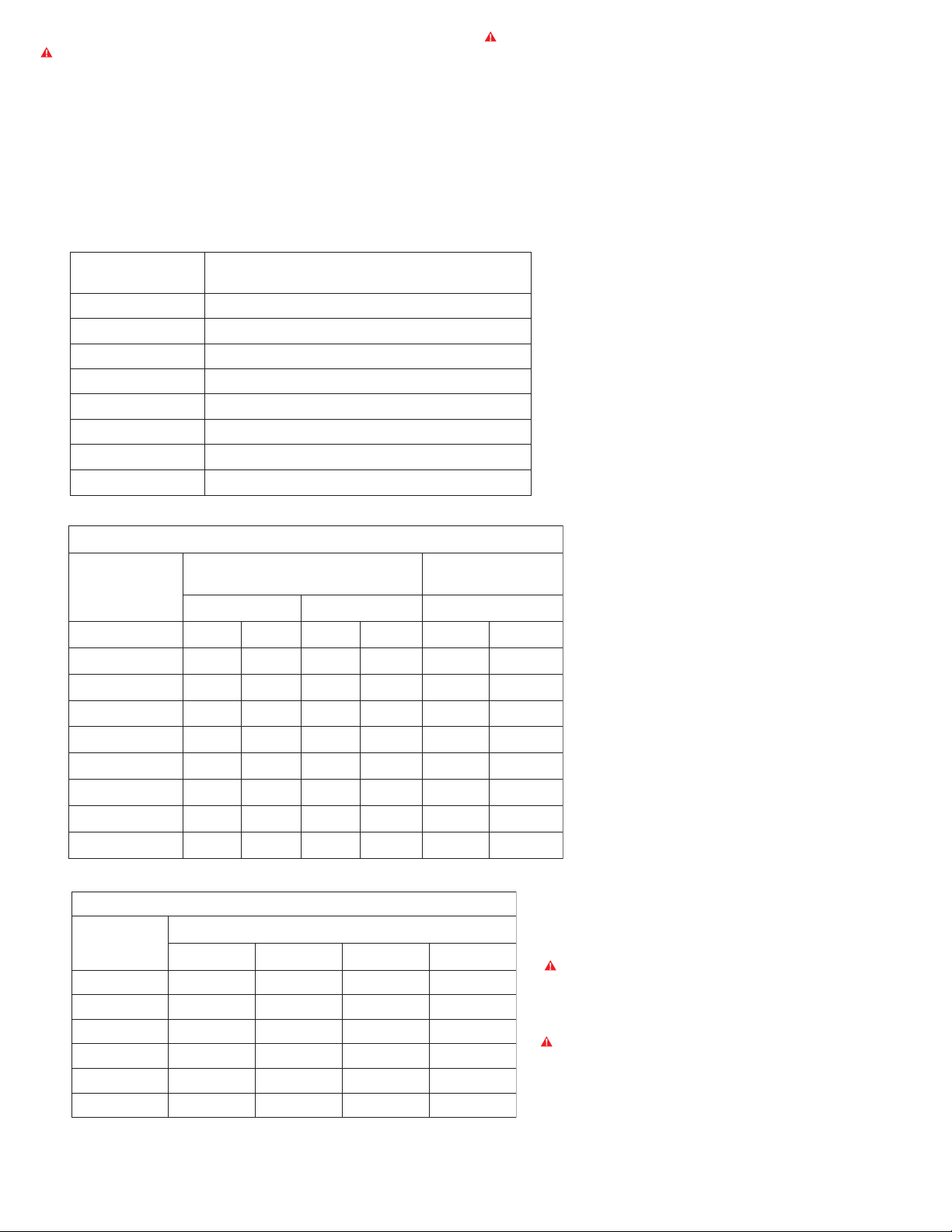
SERIES MT w/o
STROBE
SERIES MT STROBE
w/ IOB BACKBOX
INC.
Helping People Take Action
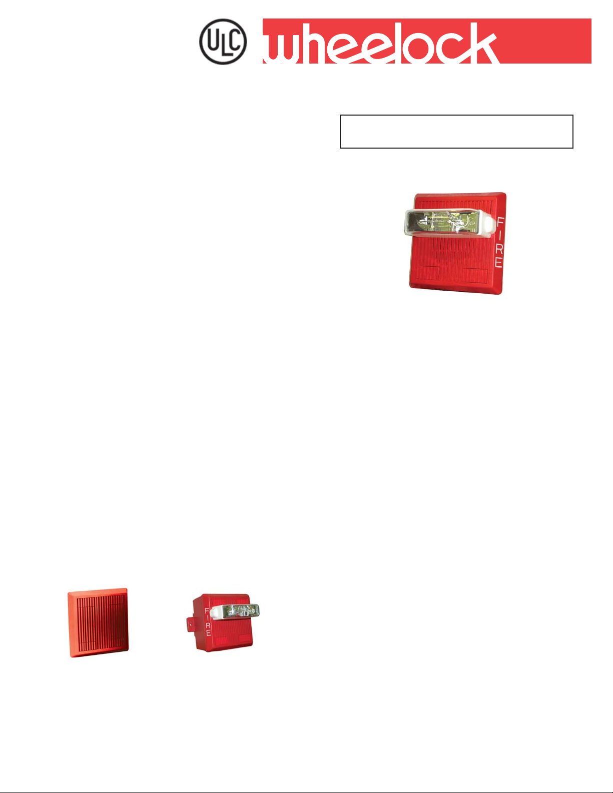
SERIES MT AND MT STROBE
MUL TITONE ELECTRONIC APPLIANCES
SERIES MT WITH STROBE
Features:
• Approvals include: CAN/ULC-S526-02 for Visual
Signaling Appliances and S tandard CAN/ULC-S525-99
for Audible Signal Appliances
• Designed to meet or exceed NFP A/ANSI St andards
and ADA Accessibility Guidelines. Meet OSHA 29
Part 1910.165
• Series MT appliances have IN and OUT wiring
terminations that accept two #12 to #18 American
Wire Gauge (AWG) wires at each terminal. Inputs are
polarized for compatibility with standard reverse
polarity type supervision
• One alarm appliance with (8) eight selective signals to
provide superior sound penetration for various ambient
and wall conditions with two field selectable sound
output levels
• Code-3 Horn and T one meet ANSI/NFP A temporal
pattern for standard emergency evacuation signaling
• Audible and strobe can operate from a single NAC
circuit with any of the (8) eight audible sounds
• MT S trobe models available with 1575 candela
ratings for independent or single input activations and
can be synchronized using Wheelock’s SM or DSM
sync module(s)
• Selectable input voltage on non-strobe versions
• Mounts to either 4" square or double gang boxes
(important for retrofit installations). Attractive flush or
surface mounting
• No additional trimplate required for flush mounting
SM
For Weatherproof MTWP See Data Sheet S9004C
Copyright 2005 Wheelock, Inc. All rights reserved.
14
Page 2
NOTE: All CAUTIONS and WARNINGS are identified by the symbol . All warnings are printed in bold capital letters .
WARNING: PLEASE READ THESE SPECIFICATIONS AND INSTALLATION INSTRUCTIONS CAREFULLY BEFORE USING,
SPECIFYING OR APPLYING THIS PRODUCT. FAILURE TO COMPLY WITH ANY OF THESE INSTRUCTIONS, CAUTIONS
AND WARNINGS COULD RESULT IN IMPROPER APPLICATION, INST ALLATION AND/OR OPERATION OF THESE
PRODUCTS IN AN EMERGENCY SITUATION, WHICH COULD RESULT IN PROPERTY DAMAGE, AND SERIOUS INJURY OR
DEATH T O YOU AND/OR OTHERS.
General Notes:
• Strobes are designed to flash at 1 flash per second minimum over their voltage range.
• All candela ratings represent minimum effective Multitone Strobe intensity.
• MT Strobe models are Listed under Standard CAN/ULC-S526-02 for Visual Signaling and under Standard CAN/ULC-S525-99 for
Audible Signal Devices for Fire Alarm Systems for indoor use with a temperature range of 0°C to 49°C (32°F to 120°F)
and maximum humidity of 93% ± 2%.
Alarm Tones
ENOT
NROH)suounitnoC(NROHDNABDAORB
LLEB)taepeR/NO.ces70.0(DETALUDOMzH0651
NROH
EMITHCRAMtaepeR/FFO.ces52.0/NO.ces52.0(NROH
NROH3-EDOC)nrettaPlaropmeT14.3SISNA(NROH
ENOT3-EDOC)nrettaPlar
POOHWWOLS )taepeR/FFO.ces5.0/NO.ces0.4(PEEWSzH0021-005
NERIS)taepeR/NO.ces0.1(PEEWSz
OL/IH)etanretlA/NO.ces52.0(zH008/0001
SENOTMRALA
NOITPIRCSEDNRETTAP
opmeT14.3SISNA(zH005
H0021-006
Specifications
noitroPelbiduAenotitluMrofsgnitaRtnerruCdnaABd:1elbaT
enoT
CDV42@CDV21@CDV42dna21@
IHDTSIHDTSIHDTS
nroH040.0320.0001.0020.09939
lleB410.0210.0130.0010.02978
aM040.0320.0001.0020.09939
neriS630.0320.0280.0020.08939
OL/IH020.0410.0440.0210.03988
nroHemiThcr
nroH3-edoC040.0320.0001.0020.09939
enoT3-edoC820.0710.0060.0510.05909
poohWwolS840.0620.0001.0520.09
)SPMA(sgnitaRtnerruCebortS:2elbaT
CLU
CDV42dna21
egnaRegatloV
CDV0.02090.871.-831.
CDV0.42060.041.-490.
CDV0.13540.421.-760.
CDV5.01- 132.CDV0.21- 971.CDV6.51- 161.-
W575142-TMW5742-TMW5751
sgnitaRtnerruCegarevACLU
949
tnerruCegarevAdetaRCLU
21-TMW5742PWTM
sgnitaRciohcenAABd
99
-525-CLU/NACreP
Note: If the strobe and audible operate on
the same circuit, add the strobe current
from T able 2 to the audible current from
T able 1.
For Peak and Inrush current across the
listed voltage range refer to Installation
Instructions.
CAUTION: This setting is acceptable only for general
signaling (non-fire alarm) use. Use the “high” dBA setting
with this tone or use a different tone for public mode fire
alarm service.
WARNING: FOR ULC VERSIONS THESE APPLIANCES
WERE TESTED TO THE OPERA TING VOLT AGE OF
20.0 - 31.- VOLTS FOR 24V MODELS AND 10.5 - 15.6
VOLTS FOR 12V MODELS USING FIL TERED (DC) OR
UNFILTERED FULL-W A VE-RECTIFIED (FWR). APPL Y 80%
AND 110% OF THESE VOL T AGE V ALUES FOR SYSTEM
OPERA TIONS.
15
Page 3

Wiring Diagrams (for all models)
MT SIGNAL
FROM
PRECEDING
APPLIANCE,
SM/DSM or
FACP
TO NEXT
+
-
+
SIGNAL
+
APPLIANCE
-
OR EOLR
-
AUDIBLE SIGNAL AND STROBE
OPERATE INDEPENDENTLY
FROM
+
PRECEDING
AUDIBLE OR
--
FACP
FROM
++
PRECEDING
STROBE O R
-
FACP
+
ORDERING INFORMATION
rebmuNledoMedoCredrOegatloVtupnIalednaCdetaRCLU***snoitpOgnitnuoM
*R-42/21-TM320542/21- R,P,O,M,L,F,E,D
*W-42/21
-TM420542/21- R,P,O,M,L,F,E,D
WF-W575121-TM16492157R,P,O,M,L,F,E,D
WN-W575121-TM74792157R,P,O,M,L,F,E,D
RF-W575142-TM2
WF-W575142-TM06494257R,P,O,M,L,F,E,D
WN-W575142-TM93794257R,P,O,M,L,F,E,D
WU-W575142-TM65134257R
RF-W5742-PWTM024842**57M
WF-W5742-PWTM211342**57M
WN-W5742-PWTM447942**57M
2484257R,P,O,M,L,F,E,D
AUDIBLE SIGNAL AND STROBE
OPERATE IN UNISON. RED AND
+
TO NEXT
AUDIBLE OR
EOLR
TO NEXT
STROBE OR
EOLR
-
--
+
AUDIBLESTROBE
BLACK SHUNT-WIRES ARE
SUPPLIED.
FROM
PRECEDING
APPLIANCE
OR FACP
+
--
RED
BLACK
-
+
STROBE AUDIBLE
+
-
TO NEXT
+
APPLIANCE
OR EOLR
NOTE:
*MT-12/24 Audible can be used with Wheelock’s
RSSP Multi-Candela for applications requiring 15,
30, 75, 110 cd Wall Strobes.
**MTWP-2475W is Weatherproof and rated for 75
cd @ -35°C. See Data Sheet S9004C or Installation
,P,O,M,L,F,E,D
Instruction P84150.
***For additional information on mounting please
refer to Data Sheet S7000.
WARNING: CONT ACT WHEELOCK FOR THE CURRENT “INST ALLA TION INSTRUCTIONS” (P82467 MT -12/24, P84155 MT w/
Strobe) “GENERAL INFORMA TION” SHEET (P82380) ON THESE PRODUCTS. THESE DOCUMENTS DO UNDERGO PERIODIC CHANGES.
IT IS IMPORTANT THA T YOU HA VE CURRENT INFORMA TION ON THESE PRODUCTS. THESE MA TERIALS CONT AIN IMPORTANT
INFORMA TION THAT SHOULD BE READ PRIOR TO SPECIFYING OR INST ALLING THESE PRODUCTS, INCLUDING:
• TOTAL CURRENT REQUIRED BY ALL APPLIANCES CONNECTED TO SYSTEM SECONDAR Y POWER SOURCES.
• FUSE RATINGS ON NOTIFICATION APPLIANCE CIRCUITS TO HANDLE PEAK CURRENTS FROM ALL APPLIANCES ON
THOSE CIRCUITS.
• COMPOSITE FLASH RATE FROM MULTIPLE STROBES WITHIN A PERSON’S FIELD OF VIEW.
• THE VOLT AGE APPLIED TO THESE PRODUCTS MUST BE WITHIN THEIR RA TED INPUT VOL TAGE RANGE.
• INSTALLATION IN OFFICE AREAS AND OTHER SPECIFICA TION AND INST ALLA TION ISSUES.
• USE STROBES ONL Y ON CIRCUITS WITH CONTINUOUSLY APPLIED OPERATING VOLTAGE. DO NOT USE STROBE ON
CODED OR INTERRUPTED CIRCUITS IN WHICH THE APPLIED VOLTAGE IS CYCLED ON AND OFF AS THE STROBE MAY
NOT FLASH.
• FAILURE TO COMPLY WITH THE INST ALLATION INSTRUCTIONS OR GENERAL INFORMATION SHEETS COULD RESULT
IN IMPROPER INST ALLATION, APPLICA TION, AND/OR OPERATION OF THESE PRODUCTS IN AN EMERGENCY
SITUA TION,WHICH COULD RESUL T IN PROPERTY DAMAGE AND SERIOUS INJUR Y OR DEA TH TO YOU AND/OR OTHERS.
• CONDUCTOR SIZE (AWG), LENGTH AND AMPACITY SHOULD BE TAKEN INTO CONSIDERATION PRIOR TO DESIGN AND
INST ALLATION OF THESE PRODUCTS, PARTICULARLY IN RETROFIT INSTALLATIONS.
Wheelock products must be used within their published specifications and must be PROPERLY specified, applied, installed, operated,
maintained and operationally tested in accordance with their installation instructions at the time of installation and at least twice a year
or more often and in accordance with local, state and federal codes, regulations and laws. Specification, application, installation,
operation, maintenance and testing must be performed by qualified personnel for proper operation in accordance with all of the latest
National Fire Protection Association (NFPA), Underwriters’ Laboratories (UL), National Electrical Code (NEC), Occupational Safety
and Health Administration (OSHA), Canadian Standard for Installation of Fire Alarm Systems, Canadian Electrical Code Part 1,
local, state, county, province, district, federal and other applicable building and fire standards, guidelines, regulations, laws and
codes including, but not limited to, all appendices and amendments and the requirements of the local authority having jurisdiction
(AHJ).
16
Page 4

Architects and Engineers Specifications
The notification appliance shall be a Wheelock Series MT audible/visual appliance or equivalent. Notification appliance shall
be electronic and use solid state components. Electromechanical alternatives are not approved. Each electronic appliance
shall provide eight (8) field selectable alarm tones. The tones shall consist of: HORN, BELL, MARCH TIME HORN, CODE-3
HORN, CODE-3 TONE, SLOW WHOOP, SIREN and HI/LO. Tone selection shall be by durable dip switch assembly and not
clips or jumpers. The audible and the strobe shall be able to operate from a single NAC circuit while producing any of these
tones. The appliance shall provide two output sound levels: STANDARD and HIGH dBA. The HIGH dBA setting shall provide a
minimum 5 dBA increase in sound output at nominal voltage. The HIGH anechoic dBA measurement at 10 feet at the alarm
HORN SETTING shall be 101 dBA minimum for MT and 99 dBA minimum for MT Strobes, at nominal voltage. Operating
voltages shall be either 12 VDC or 24 VDC using filtered power or unfiltered power supply (full-wave-rectified). All models shall
have provisions for standard reverse polarity type supervision and IN/OUT field wiring using terminals that accept #12 to #18
AWG wiring.
Combination audible/visual appliances shall incorporate a Xenon flashtube enclosed in a rugged Lexan
with solid state circuitry. Strobe shall produce a flash rate of one (1) flash per second minimum over the voltage range. The
strobe intensity shall be rated per CAN/ULC-S525-99 for Candela. The 15/75 candela strobe shall be specified when 15
candela with 75 candela intensity on-axis is required. Series Strobe Models shall incorporate circuitry for synchronized strobe
flash and shall be designed for compatibility with Wheelock: SM and/or DSM Sync Modules. The strobes shall not drift out of
synchronization at any time during operation. If the module fails to operate (i.e., contacts remain closed), the strobes shall
revert to a non-synchronized default flash rate.
The Sync Module shall be designed and available in two versions; the SM-12/24 for control of a Class B circuit; and a dual
output version, the DSM-12/24 for control of either Class A or multiple Class B circuits. Rated average current requirement for
the SM-12/24 shall be .017/.028 amperes; the DSM-12/24 shall be .020/.035 amperes. A single circuit SM Sync Module shall
be capable of handling a 3 ampere load @ 12 or 24 VDC; dual circuit DSM Sync Modules shall be capable of handling a load
of 3 amperes per circuit @ 12 or 24 VDC.
All Listed strobe appliances shall incorporate low temperature compensation to insure the lowest possible current
consumption. Strobe activation shall be via independent input or from the same input circuit as the audible.
The combination audible/visual appliances may be installed indoors and surface or flush mounted. They shall mount to
standard electrical hardware requiring no additional trimplate or adapter. The aesthetic appearance shall not have any
mounting holes or screw heads visible when the installation is completed. The appliance shall be finished in a textured red
color.
The audible appliance may be installed indoor or outdoor with the proper back box.
®
lens or equivalent
NOTE: Due to continuous development of our products, specifications and offerings are subject to change without notice in
accordance with Wheelock Inc. standard terms and conditions.
WE SUPPORT AND ENCOURAGE NICET CERTIFICATION
ASSEMBLED IN THE USA
3 YEAR WARRANTY
Distributed By:
17
NA TIONAL SALES OFFICE
Canada: 800-397-5777
E-Mail: Info@wheelockinc.com
http://www.wheelockinc.com
273 BRANCHPORT AVENUE • LONG BRANCH, NJ 07740 • TEL: 732-222-6880 • FAX: 732-222-2588
S2000C 02/05
 Loading...