

Page 1

273 Branchport Ave.
Long Branch, N.J. 07740 Thank you for using our products.
(800) 631-2148
www.wheelockinc.com
INSTALLATION INSTRUCTIONS
MODEL FZC-3
FIXED ZONE CONTROL
(3 ZONES)
Use this product according to this instruction manual. Please keep this instruction manual for future reference.
1. APPLICATION INFORMATION
The FZC-3 is a Fixed Zone Control that performs the central control, switching and signaling required to provide selective Zone Paging, All Call,
Background Music Mute, Page Alert Tone Signaling and Night Ringer. The FZC-3 provides 3 separate zones of One Way paging.
The FZC-3 can also be optioned to be used with a wide variety of system amplifier configurations which can include various combinations of
25V/70V central or zone amplifiers or amplified One Way paging speakers.
The FZC-3 is compatible with most EKSU, KSU (1A2), and PBX telephone systems. It connects to either an unused loop start CO port or a 600
ohm low power audio page port. When connected to an unused CO port, DTMF telephones may be used to operate the FZC-3. When connected
to a page port, the page port must provide a dry contact closure and transmit DTMF tones. The FZC-3 can also be used in "Ring Start"
applications (Centrex, Station Level) by using a (TPI-100) telephone paging interface.
Paging is accessed from any telephone by pressing the CO line button (EKSU & KSU), or dialing the number assigned to paging. Three (3)
individual zones are selected by dialing 1,2 or 3. All Call is selected by dialing 0.
When any Zone or All Call selection is made, a page alert tone will be heard at all the speakers in the selected zone. The tone will also be heard
by the paging telephone to provide verification of connection to the selected speakers.
2. INTERFACE INFORMATION:
The FZC-3 can be connected directly to:
1. A telephone for stand alone paging.
2. A telephone system's unused CO line/trunk port.
3. A telephone system's 600 ohm audio page port (See Figure 11, page 8).
Using a TPI-100 connected to the FZC-3 then can be connected to:
(The FZC-3 should not be hooked directly to the Public Switched Telephone Network, as this can result in improper operation of the unit
and or the Public Switched Telephone Network)
1. An analog station level line.
2. A Centrex line.
3. CONFIGURATION DESCRIPTIONS
The amplifier type (central or zone) is configured as described in Chart 1.
If central amplification is used, then the choice of one or two central amplifiers is configured, as described in Chart 2.
The FZC-3 Talk Battery output or TPI-100 interface function can be selected depending upon the paging access source, as shown in Chart 3.
:
:
Chart 1: Amplifier Type Configuration Function
Function Choices
Amplifier Type
1. Central Amplifier:
25V or 70V audio output switched to speakers with line
matching transformers.
2. Zone Amplifier:
600 ohm audio input switched to separate zone
amplifiers connected to paging speakers with 25V/70V
line matching transformers; or switched to PRM-150
line preamplifiers or connected to amplified One Way
paging speakers.
Chart 2: 1 or 2 Central Amplifiers Configuration Function
Function Choices
1 or 2 Central Amplifiers
1. (1CA) One central amplifier for both paging and
background music. Paging in any zone will mute
music in all zones.
2. (2CA) Two central amplifiers, one for paging and
one for background music. Music is muted only in
the activated zone.
P83273 A
Sheet 1 of 10
Page 2
Talk Battery Output System Configuration Function
Function Choices for System
Talk Battery Output
Depending upon system amplifier configuration, the amplifier functions and background music mute operation will vary, as shown in Chart 4.
(A) One (1) Central Amplifier Paging & Music Paging any zone will mute
(B) Two (2) Central Amplifiers One for Paging
(C) Zone Amplifiers,
Line Preamplifiers
Speaker Amplifiers
4. APPLICATION DIAGRAMS
The following application diagrams show the seven basic system configurations of the FZC-3. All of these configurations are possible with the
appropriate configured switch selections. Figures 1, 2 and 3 are typical configurations using central amplifiers. Figure 4 is a typical configuration
using amplified speakers. Figures 5 and 6 are typical configurations using zone amplifiers.
or TPI-100 Interface 2. Interface to a TPI-100.
Amplifier Configurations, Functions, and Music Mute Operation
Amplifier Configuration Function Music Mute Operation
:
1. For stand alone telephone, unused CO line/trunk
Chart 3:
port, and 600 ohm audio page port.
Chart 4:
music in all zones.
and
One for Music
Paging & Music
Music is muted only in the
paged zone(s).
Music is muted only in the
paged zone(s)
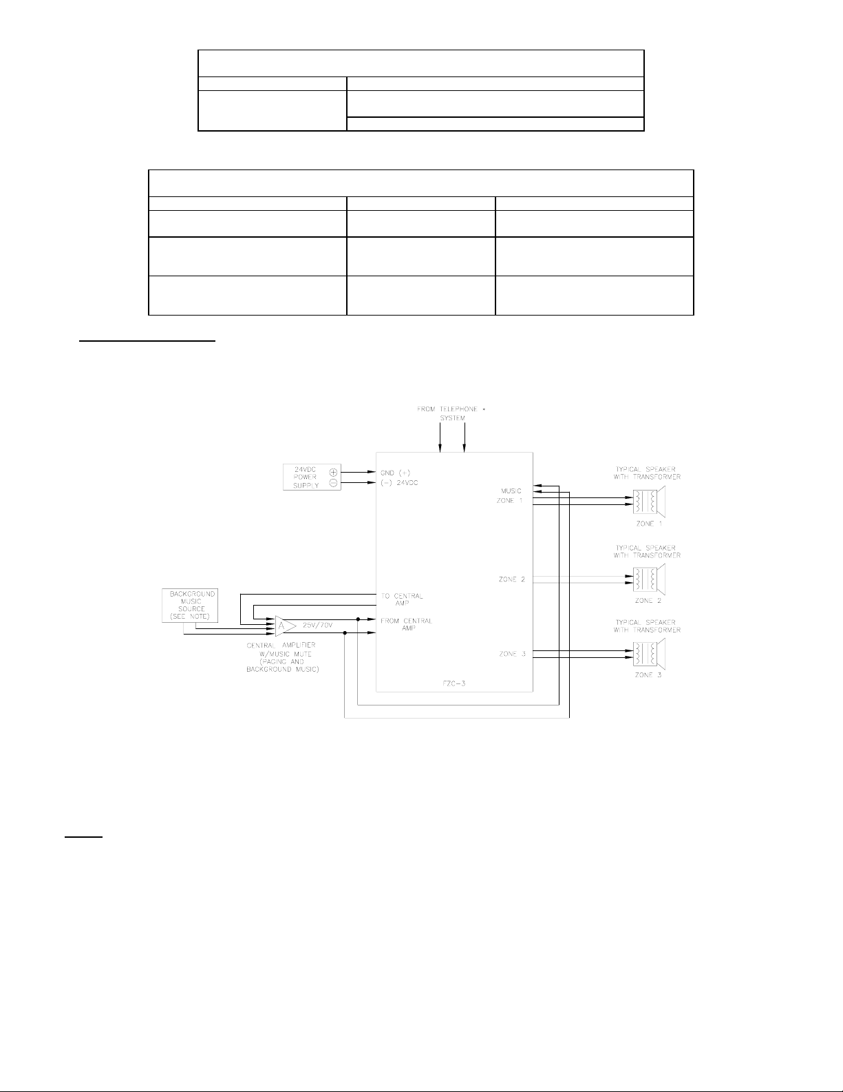
Figure 1.
One Central Amplifier which has music mute, page input and music input.
In this application, one central amplifier is used for both paging and background music. The central amplifier has music muting and separate
inputs (volume controls) for paging and music. The system uses speakers with built-in line matching transformers for paging.
1. If a stand alone telephone, unused Co Line/truckport, or 600 ohm audio page port is use connections are made directly to the FZC-3.
2. If the central amplifier does not provide music mute, then the background music source is connected as shown in Figure 2.
:
NOTES
If Station Level or Centrex Line a TPI-100 is required.
Figure 2.
One Central Amplifier which does not have music mute, and which has only one input.
P83273 A
Sheet 2 of 10
Page 3
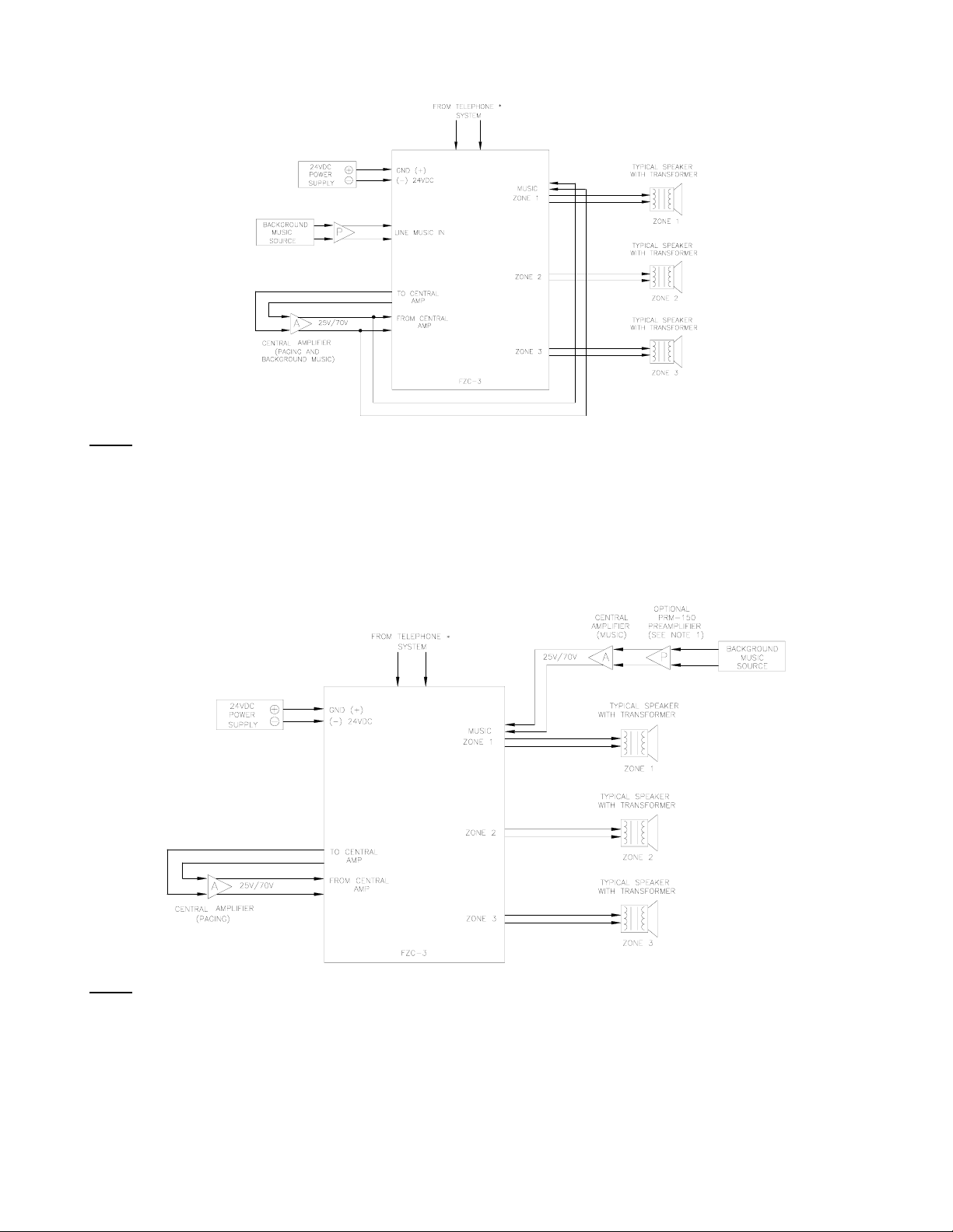
In this application, the one central amplifier for both paging and background music. The central amplifier does not provide music muting, and has
only one input (one, or no volume control). The system uses speakers with built-in line matching transformers for paging.
1. If a stand alone telephone, unused Co Line/truckport, or 600 ohm audio page port is use connections are made directly to the FZC-1 If
2. If the background music source has no volume control, then the optional PRM-150 must be connected between the background music
:
NOTES
Station Level or Centrex Line a TPI-100 is required.
source and the FZC-3 music input, as shown.
Figure 3.
Two Central Amplifiers, one for paging and one for background music.
In this application, two central amplifiers are used, one for paging and one for background music. The system uses speakers with built-in line
matching transformers for paging.
1. If a stand alone telephone, unused Co Line/truckport, or 600 ohm audio page port is use connections are made directly to the FZC-3. If
:
NOTES
Station Level or Centrex Line a TPI-100 is required.
2. If both the music central amplifier and the background music source have no volume controls, then a PRM-150 must be connected between
the background music source output and the music central amplifiers input.
Figure 4.
Amplified Speakers
In this application, amplified speakers are used for paging and for background music. A PRM-150 preamplifier is used with the background music
source.
P83273 A
Sheet 3 of 10
Page 4
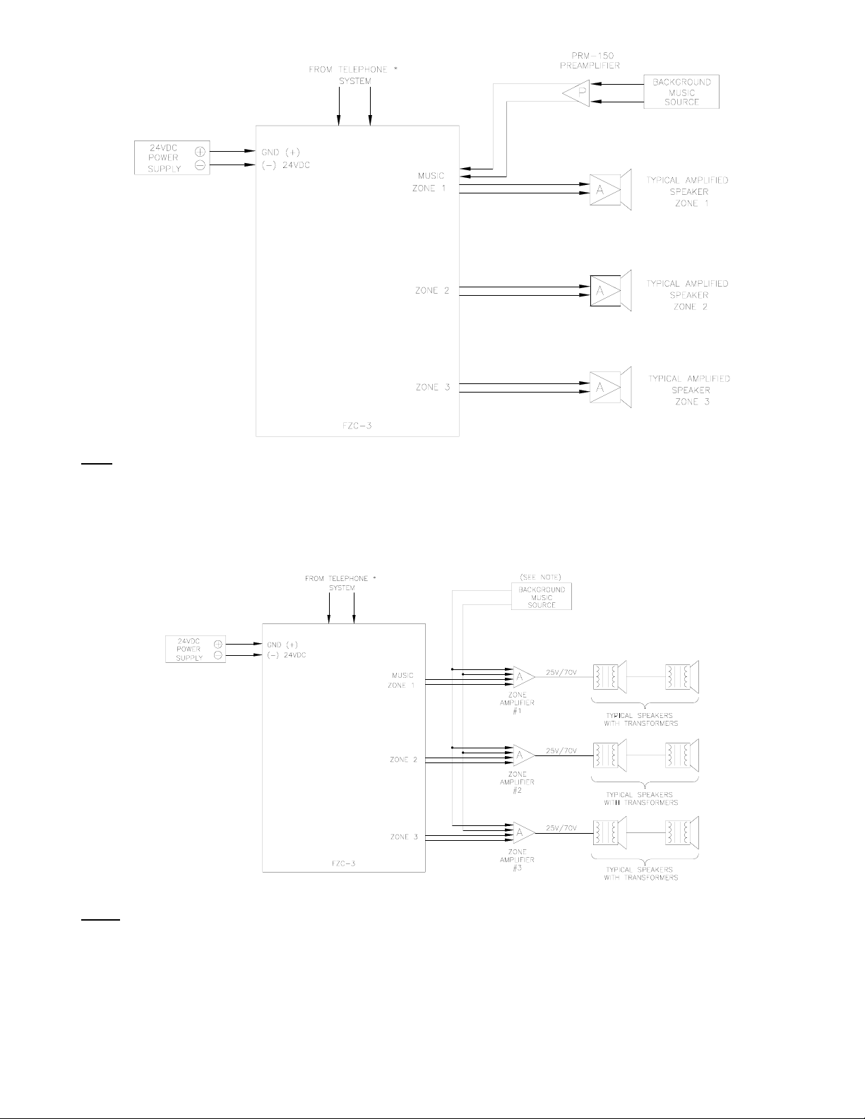
: If a stand alone telephone, unused Co Line/truckport, or 600 ohm audio page port is use connections are made directly to the FZC-3. If
NOTE
Station Level or Centrex Line a TPI-100 is required.
Figure 5.
Zone Amplifiers which have music mute, page inputs and music inputs.
In this application, the zone amplifiers for both paging and background music have music muting, and separate inputs (volume controls) for paging
and music. The system uses speakers with line matching transformers.
:
NOTES
1. If a stand alone telephone, unused Co Line/truckport, or 600 ohm audio page port is use connections are made directly to the FZC-3. If
Station Level or Centrex Line a TPI-100 is required.
2. One music source may be used for all zones, or different music sources can be used for different sources.
Figure 6.
Zone Amplifiers which do not have music mute, and which have one input.
In this application, the zone amplifiers for both paging and background music do not provide music muting, and have only one input (with or
without volume control). The system uses speakers with line matching transformers.
P83273 A
Sheet 4 of 10
Page 5
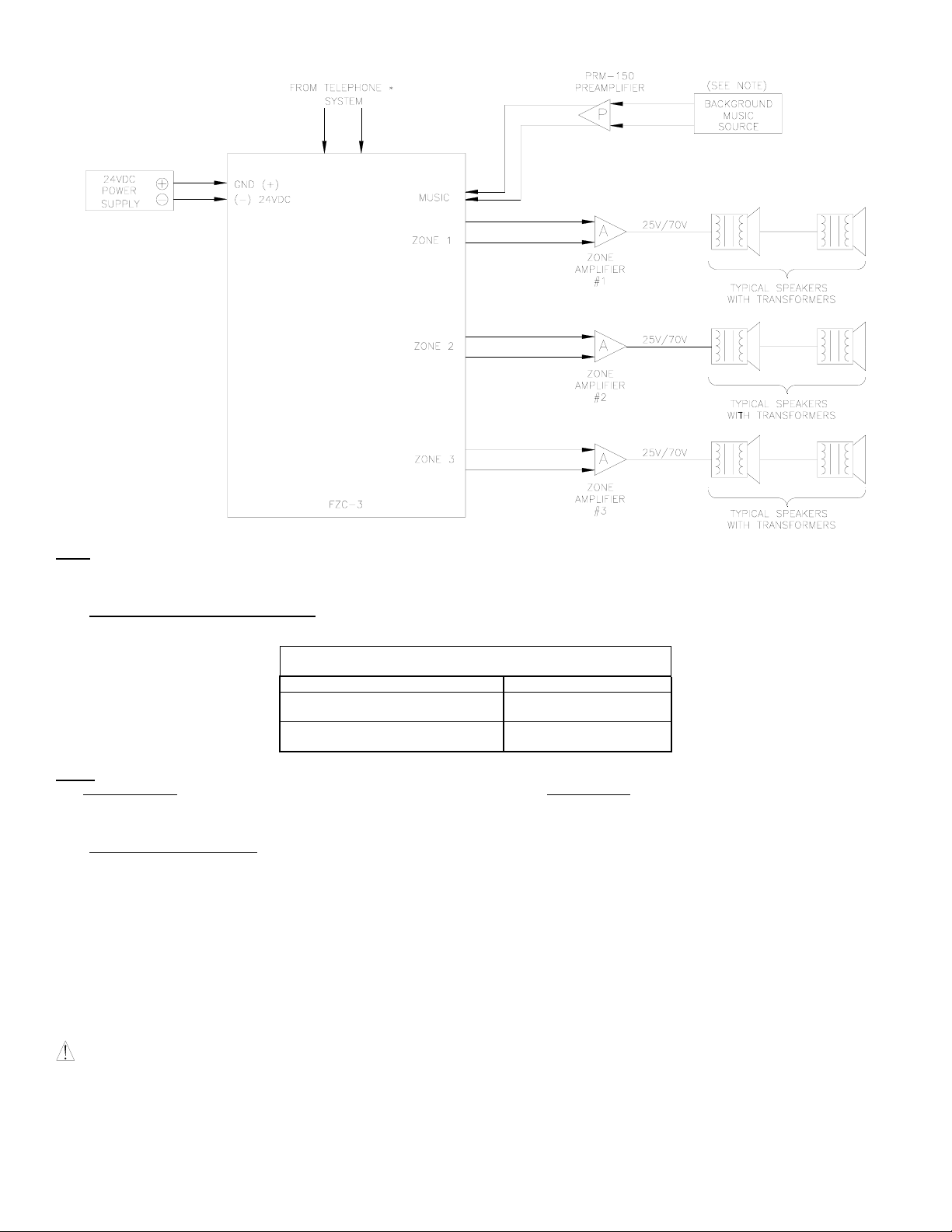
: If a stand alone telephone, unused Co Line/truckport, or 600 ohm audio page port is use connections are made directly to the FZC-3. If
NOTE
Station Level or Centrex Line a TPI-100 is required.
5. AMPLIFIER AND SPEAKER CAPACITY
Maximum amplifier and speaker capacity for each zone group and the total system is shown in Chart 5.
The Fixed Zone Control can switch its preamplifier audio output to the 600 ohm inputs of up to 150 zone amplifiers or speaker- amplifiers.
NOTE:
This TOTAL SYSTEM
leave 125 amplifier inputs for the remaining zones.
6. MOUNTING INSTRUCTIONS:
The FZC-3 is designed for surface wall mounting near the telephone system. Remove the top cover by pushing on the latch at the bottom of the
housing base with a small screw driver. See Figure 7.
Figure 8 is the mounting template. To mount the base (containing the PC Board Assembly) to the wall space the 2 mounting screws provided
horizontally on 2.750" centers.
CAUTION:
Fire Protection Association (NFPA).
audio output can be distributed to the three (3) zones, provided no SINGLE ZONE exceeds 25 amplifier inputs, which would
These devices are not intended for use in hazardous locations as defined by the National Electrical Code (NEC) and by the National
Maximum Amplifier and Speaker Capability
Amplifier Configuration Total System
Central Amplifier(s) 100W @ 70V
Zone Amplifiers or
Speaker-Amplifiers
Chart 5:
25W @ 25V
150 Amplifier
Inputs
P83273 A
Sheet 5 of 10
Page 6

7. SPECIFICATIONS:
8. ZONE ACCESS AND DIALING CODES:
FIGURE 7.
Supply Voltage (Nominal) -24VDC
Supply Voltage Range -21.6VDC to -26.4VDC
Alert Tone Frequency 1100Hz +/-10%
Alert Tone Duration 500m Sec. +/-10%
Alert Tone Level (maximum) -4dBM +/-3dBM
Tip and Ring Input Level -15dBM (0.1Vrms) to +10dBM (2.4Vrms)
Music Input Level -15dBM (0.1Vrms) to +10dBM (2.4Vrms)
Tip and Ring Input Impedance 600 Ohms
Music Input Impedance 600 Ohms
Max. Output Level to Amplifier 1 0dBM (0.78Vrms)
Output Impedance to Amplifier 1 4 Ohms
Max. Input Level from Amplifier 1 25W @ 25V or 100W @ 70V (Central Amplifier Output)
Audio Output Level (Max. - Per Zone)
- Speaker - Amplifier Selected
Operating Temperature Range 0 to 49 Degrees C
Operating Humidity Range 0 to 85% RH
Off-Hook Detection Sensitivity 1850 Ohms DC Resistance (Max.)
Night Ringer Detector 0 to 100 Ohms DC Resistance (Dry Contact Closure)
Page Zone 1 Dial 1
Page Zone 2 Dial 2
Page Zone 3 Dial 3
Page All Zones (All Call) Dial 0
FIGURE 8.
Operating current Max. @-24VDC
Supply Current (Idle-BGM) 55mA
Supply Current (Nominal-1 Zone Page) 160mA
Supply Current (Maximum-All Call) 200mA
Zone Control Access Press Co Line Button, Or Dial
Chart 6.
0dBM (0.78Vrms), 600 Ohms
Chart 7.
Number Assigned To Page.
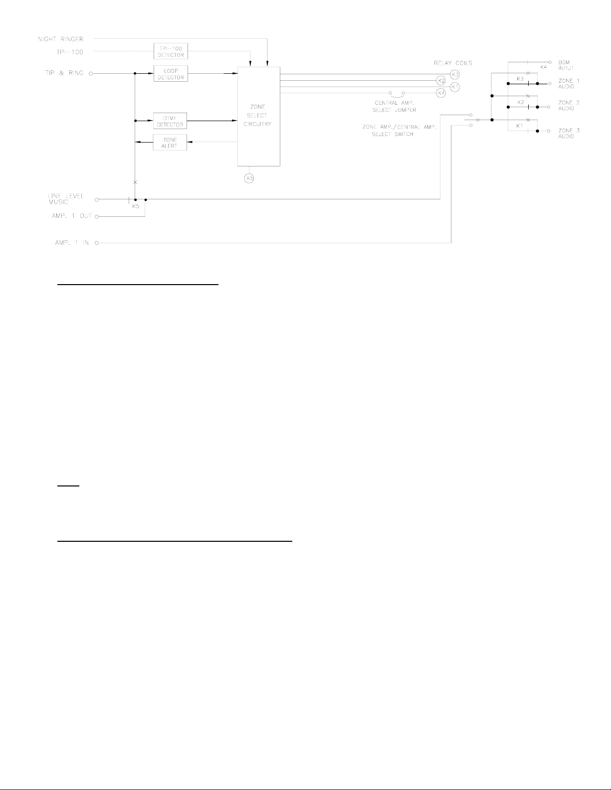
Figure 9.
Single Line Block Diagram
P83273 A
Sheet 6 of 10
Page 7
9. WIRING INSTRUCTIONS (SEE FIGURE 10):
1. Make sure 24VDC power supply is disconnected from the 115VAC power source.
2. Connect tip and ring from:
A. Stand along telephone, or
B. Telephone system's unused CO line/trunk port, or
C. Telephone system's 600 ohm, audio page port (See Figure 11), or
D. TPI-100, along with connecting the TPISW and GND.
3. Connect night ringer if used (see Figure 12).
4. Connect the background music source to TB3, terminals 3 and 4, on the FZC-3.
5. Connect the 24VDC power supply to the (-)24V and GND(+) terminals on TB1, terminals 6 and 5 respectively.
6. Connect the zone amplifier, speaker amplifiers, or speakers with transformers to the audio pair for zones 1 thru 3 on TB2 of the FZC-3.
7. If one central amplifier is used for paging and background music:
A. Connect the input of central amplifier to “TO CENTRAL AMP”, terminals 1 and 2 of TB3 on the FZC-3. Connect the output of central
amplifier to “FROM CENTRAL AMP”, terminals 5 and 6 of TB2 on the FZC-3.
B. Connect the output of central amplifier to BMG Input, terminals 1 and 2 of TB2 on FZC-3.
8. If separate central amplifiers are used, one for paging and one or more for background music:
A. Connect paging amplifier as described in 6A, above.
B. Connect output of background music amplifier(s) as described in 6B, above.
9. Connect the 24VDC power supply to the 115VAC source.
NOTE
When only one central amplifier is used, background music will be muted in all zones when a page is in progress. When separate central
amplifiers are used, background music will be muted in only the paged zone.
10. CONFIGURATION SETTING INSTRUCTIONS (SEE FIGURE 10):
1. Set the "Talk Battery/TPI-100" selector switch, SW1 (See Chart 3)
A. *To the “Talk Battery” position when connected to a telephone systems, unused CO line/trunk port, 600 ohm audio page port, or
directly to a telephone.
B. To the "TPI-100" position when connected to a TPI-100.
2. Set the "Zone Amplifier/Central Amplifier" selector switches for SW2 as required. (See Chart 1)
A. *Central Amplifier
B. Zone Amplifier
3. Set the "1CA/2CA" jumper E1 as Required. (See Chart 2)
A. 2CA
B. 1CA
*Denotes shipped configuration.
Installation, Programming and Volume Adjustment Diagram
Figure 10.
P83273 A
Sheet 7 of 10
Page 8

11. AUDIO PAGE PORT INSTALLATION INSTRUCTIONS:
The FZC-3 can be connected to an audio page port only
(A) A 600 ohm, low power page output, capable of passing DC loop current.
(B) Transmission of DTMF touch tone.
(C) A dry contact that is normally open, closes when paging and reopens when the page is completed.
If these conditions are met, then connect Tip and Ring as shown in Figure 11.
if the audio page port provides:
Figure 11.
Connecting to a 600 Ohm Audio Page Port
12. NIGHT RINGER INSTALLATION INSTRUCTIONS:
The Night Ringer works from a dry contact closure through which no more than 10mA of current will be drawn. The dry contact closure will result
in the Night Ringer function, an All Call will occur and the alert tone sent out. The alert tone will remain until the dry contact closure opens. This
P83273 A
Sheet 8 of 10
Page 9

feature will follow the dry contact closure presented between the Night Ring and GND (TB1 Pos. 7 and 8). This feature has a lower priority than
paging. Therefore if a page comes in while the Night Ringer is active, the page will take priority.
Figure 12.
Night Ringer Installation Instructions
13. OPERATING INSTRUCTIONS:
1. Pick up the telephone handset and press the CO line button (EKSU, KSU), or number assigned to paging (PBX) to access the port assigned
2. To initiate:
A. Zone Page, dial "1", “2” or "3" to select zones 1 thru 3, respectively.
B. For All-Call Page, dial "0".
NOTE: If any other digit is dialed a tone will be heard in the telephone handset and the user must hang up and begin again.
3. When paging, background music will be muted. At the conclusion of the page (i.e., phone "hangs-up"), the background music will
5. At the conclusion of the page, simply hang-up the telephone handset.
14. TROUBLE SHOOTING
Condition
1. Zone page or all call page cannot be
2. No background music. 1. Verify unit has released from last page.
3. No sound or low page volume. 1. Check presence and level of audio input at Tip and Ring terminals on TB1 of the FZC-3
4. The page alert tone is too high or too low. 1. Set the page alert Tone Volume Control in the FZC-3 to the desired level.
5. Night Ringer
to paging. (Port to which the FZC-3 has been connected).
automatically be restored.
4. When any page is initiated, an alert tone is heard both in the telephone receiver, and in all selected zones. Adjust the tone volume control in
the FZC-3 to the desired level. Note the minimum setting turns the tone off.
accessed
Check
1. Telephone system must have touch tone (DTMF) dialing
2. Check presence and polarity of voltage on (-) 24VDC and GND (+) terminals on TB4.
3. If the unit is in the Talk Battery configuration, check for the access tone at the beginning of
a page by using a telephone connected between TB3 1 and TB3 2.
2. Check background music source, and adjust its volume control, as desired.
3. Check presence of line level music input (if used) at terminals. If necessary also at
speaker amplifier, or central or zone amplifier inputs.
and if necessary also at the CO Port. (or the Audio Page Port)
2. Check presence and level of audio at the zone AUDIO output terminals on TB2 of the
FZC-3. If necessary also at speaker amplifier inputs, and central or zone amplifier inputs.
1. Verify the unit has relesed from last page.
2. Check presence of a short between TB1-7 and TB1-8.
ANY MATERIAL EXTRAPOLATED FROM THIS DOCUMENT OR FROM WHEELOCK MANUALS OR OTHER DOCUMENTS
DESCRIBING THE PRODUCT FOR USE IN PROMOTIONAL OR ADVERTISING CLAIMS, OR FOR ANY OTHER USE, INCLUDING
DESCRIPTION OF THE PRODUCT'S APPLICATION, OPERATION, INSTALLATION AND TESTING IS USED AT THE SOLE RISK
OF THE USER AND WHEELOCK WILL NOT HAVE ANY LIABILITY FOR SUCH USE.
Limited Warranty
P83273 A
Sheet 9 of 10
Page 10

Wheelock products must be used within their published specifications and must be PROPERLY specified, applied, installed, operated,
maintained and operationally tested in accordance with these instructions at the time of installation and at least twice a year or more
often and in accordance with local, state and federal codes, regulations and laws. Specification, application, installation, operation,
maintenance and testing must be performed by qualified personnel for proper operation in accordance with all of the latest National Fire
Protection Association (NFPA), Underwriters' Laboratories (UL), Underwriters’ Laboratories of Canada (ULC), National Electrical Code
(NEC), Occupational Safety and Health Administration (OSHA), local, state, county, province, district, federal and other applicable
building and fire standards, guidelines, regulations, laws and codes including, but not limited to, all appendices and amendments and
the requirements of the local authority having jurisdiction (AHJ). Wheelock products when properly specified, applied, installed,
operated, maintained and operationally tested as provided above are warranted against mechanical and electrical defects for a period of
three years from date of manufacture (as determined by date code). Correction of defects by repair or replacement shall be at
Wheelock's sole discretion and shall constitute fulfillment of all obligations under this warranty. THE FOREGOING LIMITED
WARRANTY SHALL IMMEDIATELY TERMINATE IN THE EVENT ANY PART NOT FURNISHED BY WHEELOCK IS INSTALLED IN
THE PRODUCT. THE FOREGOING LIMITED WARRANTY SPECIFICALLY EXCLUDES ANY SOFTWARE REQUIRED FOR THE
OPERATION OF OR INCLUDED IN A PRODUCT. WHEELOCK MAKES NO REPRESENTATION OR WARRANTY OF ANY OTHER
KIND, EXPRESS, IMPLIED OR STATUTORY WHETHER AS TO MERCHANTABILITY, FITNESS FOR A PARTICULAR PURPOSE
OR ANY OTHER MATTER.
USERS ARE SOLELY RESPONSIBLE FOR DETERMINING WHETHER A PRODUCT IS SUITABLE FOR THE USER'S PURPOSES,
OR WHETHER IT WILL ACHIEVE THE USER'S INTENDED RESULTS. THERE IS NO WARRANTY AGAINST DAMAGE
RESULTING FROM MISAPPLICATION, IMPROPER SPECIFICATION, ABUSE, ACCIDENT OR OTHER OPERATING CONDITIONS
BEYOND WHEELOCK'S CONTROL.
SOME WHEELOCK PRODUCTS CONTAIN SOFTWARE. WITH RESPECT TO THOSE PRODUCTS, WHEELOCK DOES NOT
WARRANTY THAT THE OPERATION OF THE SOFTWARE WILL BE UNINTERRUPTED OR ERROR-FREE OR THAT THE
SOFTWARE WILL MEET ANY OTHER STANDARD OF PERFORMANCE, OR THAT THE FUNCTIONS OR PERFORMANCE OF
THE SOFTWARE WILL MEET THE USER'S REQUIREMENTS. WHEELOCK SHALL NOT BE LIABLE FOR ANY DELAYS,
BREAKDOWNS, INTERRUPTIONS, LOSS, DESTRUCTION, ALTERATION, OR OTHER PROBLEMS IN THE USE OF A PRODUCT
ARISING OUT OF OR CAUSED BY THE SOFTWARE.
THE LIABILITY OF WHEELOCK ARISING OUT OF THE SUPPLYING OF A PRODUCT, OR ITS USE, WHETHER ON WARRANTIES,
NEGLIGENCE, OR OTHERWISE, SHALL NOT IN ANY CASE EXCEED THE COST OF CORRECTING DEFECTS AS STATED IN
THE LIMITED WARRANTY AND UPON EXPIRATION OF THE WARRANTY PERIOD ALL SUCH LIABILITY SHALL TERMINATE.
WHEELOCK IS NOT LIABLE FOR LABOR COSTS INCURRED IN REMOVAL, REINSTALLATION OR REPAIR OF THE PRODUCT
BY ANYONE OTHER THAN WHEELOCK OR FOR DAMAGE OF ANY TYPE WHATSOEVER, INCLUDING BUT NOT LIMITED TO,
LOSS OF PROFIT OR INCIDENTAL OR CONSEQUENTIAL DAMAGES. THE FOREGOING SHALL CONSTITUTE THE SOLE
REMEDY OF THE PURCHASER AND THE EXCLUSIVE LIABILITY OF WHEELOCK.
IN NO CASE WILL WHEELOCK'S LIABILITY EXCEED THE PURCHASE PRICE PAID FOR A PRODUCT.
Limitation of Liability
WHEELOCK'S LIABILITY ON ANY CLAIM OF ANY KIND, INCLUDING NEGLIGENCE AND BREACH OF WARRANTY, FOR ANY
LOSS OR DAMAGE RESULTING FROM, ARISING OUT OF, OR CONNECTED WITH THIS CONTRACT, OR FROM THE
MANUFACTURE, SALE, DELIVERY, RESALE, REPAIR OR USE OF ANY PRODUCT COVERED BY THIS ORDER SHALL BE
LIMITED TO THE PRICE APPLICABLE TO THE PRODUCT OR PART THEREOF WHICH GIVES RISE TO THE CLAIM.
WHEELOCK'S LIABILITY ON ANY CLAIM OF ANY KIND SHALL CEASE IMMEDIATELY UPON THE INSTALLATION IN THE
PRODUCT OF ANY PART NOT FURNISHED BY WHEELOCK. IN NO EVENT SHALL WHEELOCK BE LIABLE FOR ANY CLAIM OF
ANY KIND UNLESS IT IS PROVEN THAT OUR PRODUCT WAS A DIRECT CAUSE OF SUCH CLAIM. FURTHER, IN NO EVENT,
INCLUDING IN THE CASE OF A CLAIM OF NEGLIGENCE, SHALL WHEELOCK BE LIABLE FOR INCIDENTAL OR
CONSEQUENTIAL DAMAGES. SOME STATES DO NOT ALLOW THE EXCLUSION OR LIMITATION OF INCIDENTAL OR
CONSEQUENTIAL DAMAGES, SO THE PRECEDING LIMITATION MAY NOT APPLY TO ALL PURCHASERS.
8/96
P83273 A
Sheet 10 of 10
 Loading...