

Page 1

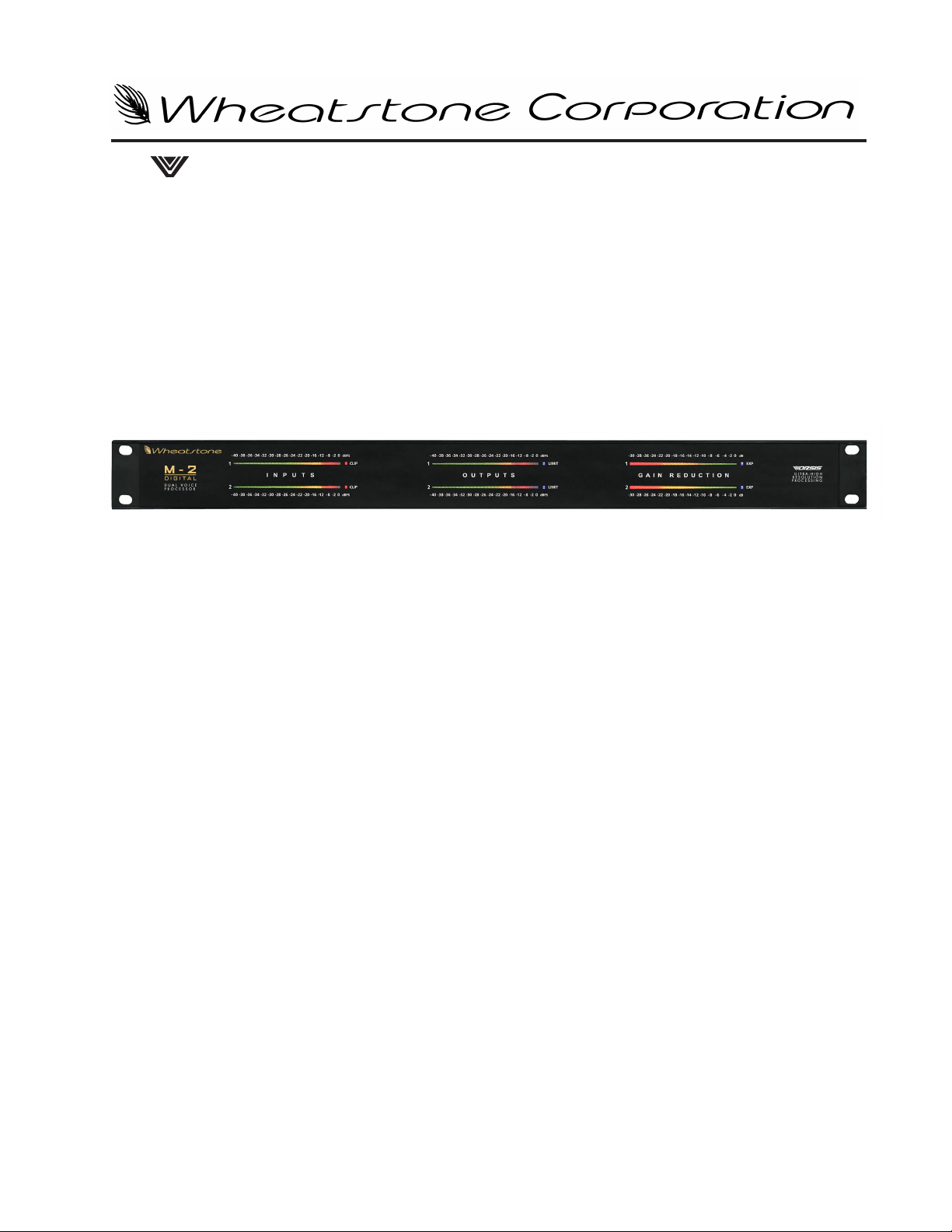
M-2 diGital
Multiband dual Voice Processor
TECHNICAL MANUAL
600 Industrial Drive, New Bern, North Carolina, USA 28562
Page 2

ORSIS
Ultra-HigH resolUtion Processing
M-2 Digital Multiband Dual Voice Processor Technical Manual - 1st Edition
©2009 Wheatstone Corporation
M-2 / October 2009
600 Industrial Drive
New Bern, North Carolina 28562
tel 252-638-7000 / fax 252-637-1285
Page 3
Attention!
Federal Communications Commission (FCC) Compliance
Notice:
Radio Frequency Notice
NOTE: This equipment has been tested and found to comply with the
limits for a Class A digital device, pursuant to Part 15 of the FCC rules. These
limits are designed to provide reasonable protection against harmful interference when the equipment is operated in a commercial environment. This
equipment generates, uses, and can radiate radio frequency energy and, if
not installed and used in accordance with the instruction manual, may cause
harmful interference to radio communications. Operation of this equipment
in a residential area is likely to cause harmful interference in which case the
user will be required to correct the interference at his own expense.
This is a Class A product. In a domestic environment,
this product may cause radio interference, in which case,
the user may be required to take appropriate measures.
This equipment must be installed and wired properly in order to assure
compliance with FCC regulations.
Caution!
Wheatstone could void the user's authority to operate this equipment.
Any modications not expressly approved in writing by
M-2 / Oct 2009
Read Me!
Page 4
ORSIS
Ultra-HigH resolUtion Processing
M-2 Digital
Multiband Dual Voice Processor
Quick Start Guide
Please inspect the contents of the shipping package to ensure that the following items
are present:
- Wheatstone M-2 Unit - Qty 1
- M-2 Technical Manual and Software CD - Qty 1
- AC Power Cord - Qty 1
- Quick Start Guide - Qty 1
Install and Connect the M-2
1. Install the M-2 in the equipment rack using at least two rack screws. If only two
screws are used they must be installed in the bottom holes of the rack ears to prevent undue stress on the front panel and possible bending.
2. Connect the microphone to the XLR female microphone input on the rear panel.
3. Connect either line level analog out or AES digital out XLR connector to your
desired signal path.
4. When using the M-2 GUI software connect rear panel Ethernet RJ--45 jack as appropriate for your intended use:
a) a direct connection to PC uses crossover CAT5 cable;
b) a connection to your LAN requires a straight through CAT5 cable
between the M-2 and the Ethernet switch or HUB.
5. Connect the AC power cord to the M-2 rear panel connector and then plug it into
AC power. The M-2 unit will power up.
M-2 / Oct 2009
Read Me! - page 1
Page 5
Installing GUI Software
The M-2 must be controlled using the included Microsoft Windows-based PC GUI
software. To install the software insert the M-2 software CD into a Windows XP/2000
computer’s CD drive and follow the steps below to install the software. If the software
installation does not automatically start when the CD is inserted into the drive, you can
start the installation manually by:
- Clicking Start
- Then click Run
- Then click Browse
- Browse the “My Computer” device tree to locate the CDROM device and
then double click it.
- When the contents of the CDROM drive appear in the window, locate the
autorun.inf or M2GUISETUP_X_X_X.EXE le on the CDROM and double
click it.
- Follow the on screen instructions to complete the GUI installation.
Configuring the M-2 IP Address
*
Once the GUI has been installed on the host PC it’s time to congure it and the M-2
so that they can communicate with each other. This requires conguration for both the
M-2 and the remote GUI so that they agree on the networking parameters.
PLEASE NOTE: As shipped from the factory, the M-2 is pre-programmed
with an IP address of 192.168.1.192, a subnet of 255.255.255.0, and a gateway of
192.168.1.1. If these settings will work in your application, you DO NOT need to
change the M-2’s IP address. Proceed to following section, Conguring the GUI.
Before starting the conguration procedure, please
locate and carefully make a note of the M-2’s 12-digit
MAC Address which is located on a label either on the
top cover or the rear panel.
Note that if the MAC address is not entered carefully and correctly in the following steps, the M-2’s IP
address will not be changed!
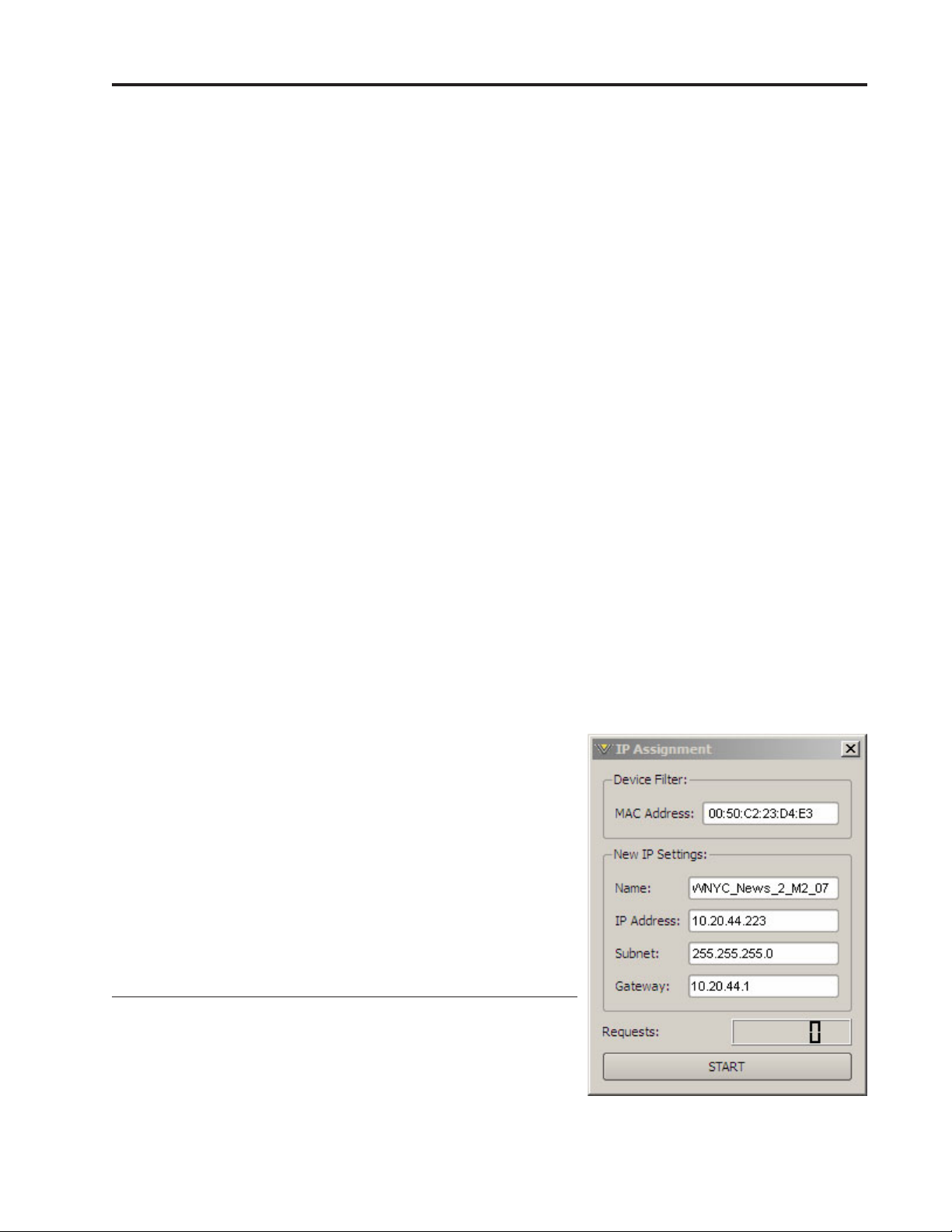
Start the M-2 GUI software. Then right click on the
control area of the GUI and select Hardware/Assign IP
Address. The window on the right will appear:
*
The M-2 does not support DHCP (Dynamic Host Conguration Protocol) and therefore it requires a static TCP/IP address on
the Network it is connected to. Its presence on the network will not
interfere with DHCP addressing of other network connected devices
as long as the IP address that is congured for the M-2 does not
conict with the address of any other device on the network. Please
consult your friendly IT manager if necessary.
M-2 / Oct 2009
M-2 / Aug 2013
Read Me! - page 2
Page 6
Next, carefully enter your M-2’s MAC address in the MAC Address eld. The MAC
address must be carefully entered because the GUI will “send” the IP address information to the device that owns the MAC address that was entered in this step. If the MAC
address is incorrect, the M-2 will never “hear” it.
Next, enter a pet name for your M-2, like AirStudio1, etc.
Then, enter the IP address that you wish the M-2 to have, noting that this address
must be unique if the M-2 will be communicating over your network.
Next enter the desired Subnet Mask and Gate-
way IP addresses.
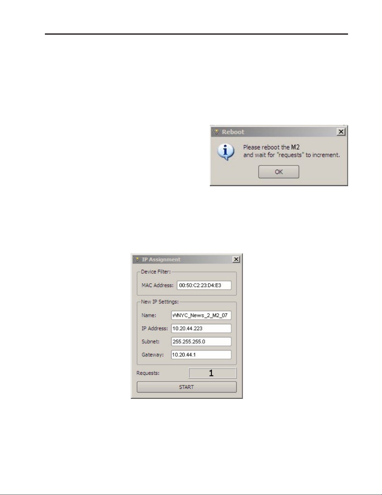
Once this is done, click the “Start” button at
the bottom of the IP address conguration box.
A message similar to the one on the right should
appear:
Click OK. Remove power to the M-2 for a
few seconds and then reapply it.
As the M-2 is booting up, the “Requests” number in the IP Assignment window
should increment to something other than zero (please see the bottom of the image on
the right). When this occurs the M-2 has received and acknowledged its new IP address
and is now ready for use on your network. Click the X in the upper right corner of the
IP Assignment window to dismiss the dialog.
M-2 / Oct 2009
Read Me! - page 3
Page 7
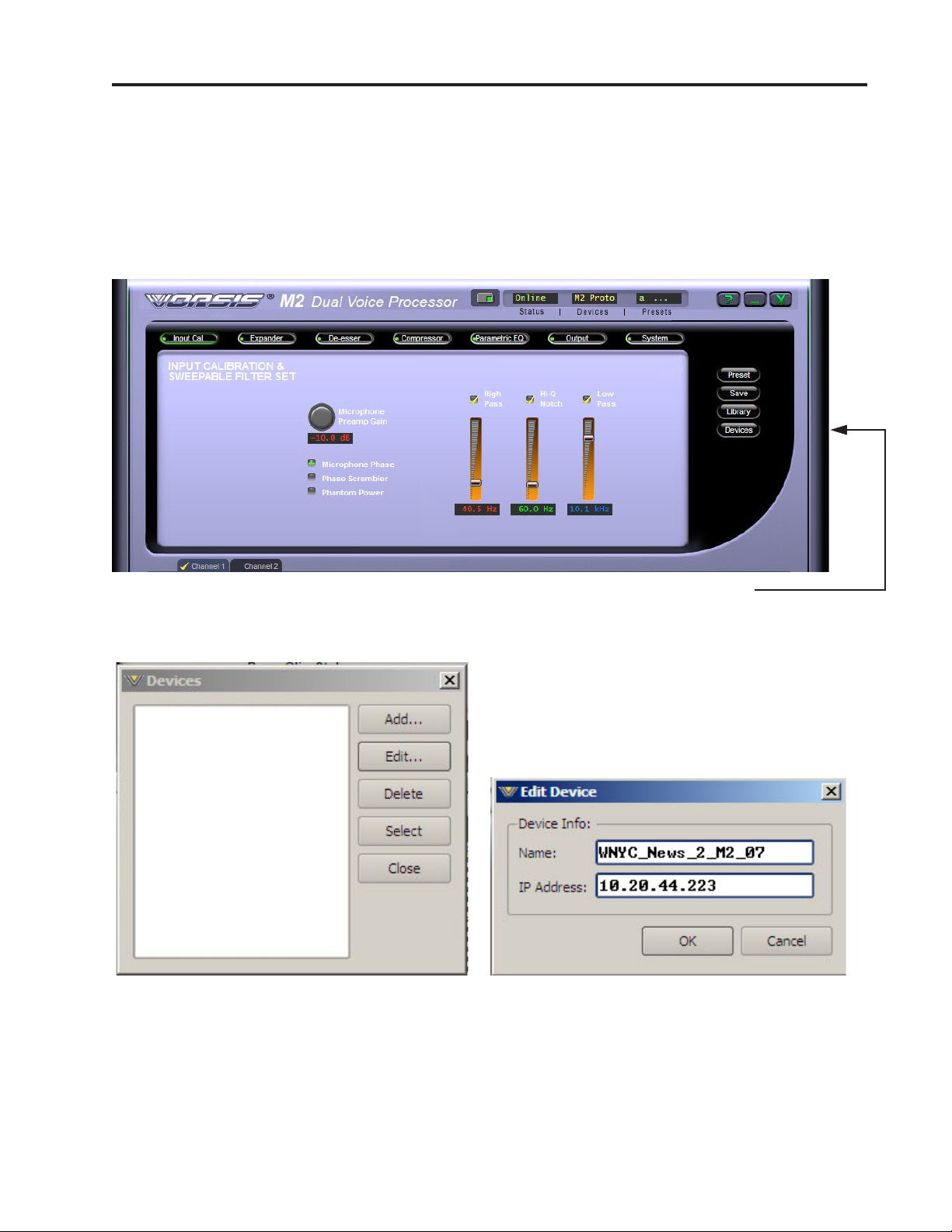
Configuring the GUI
Now that the M-2 has its own TCP/IP identity, we must congure the GUI so that it
can talk to the M-2. This is done by adding “devices” to the list of M-2’s that the GUI
knows about. To do this, locate and click on the “Devices” button located along the right
side of the GUI.
Location of “Devices” button
When this is done, the following window will pop up:
Next, click the “Add” button and a new
dialog box will appear. This is how new de-
vices are added or the conguration of existing
devices modied.
First, enter the same pet name that you used when you assigned the IP address to the M-2.
The above dialog shows us adding a new device called “WNYC_News_2_M2_07.”
Then enter the IP address that you congured the M-2 for in the previous steps. Note that
it is always best to completely delete any existing data in the IP Address box and then enter
the complete address from scratch.
M-2 / Oct 2009
Read Me! - page 4
Page 8
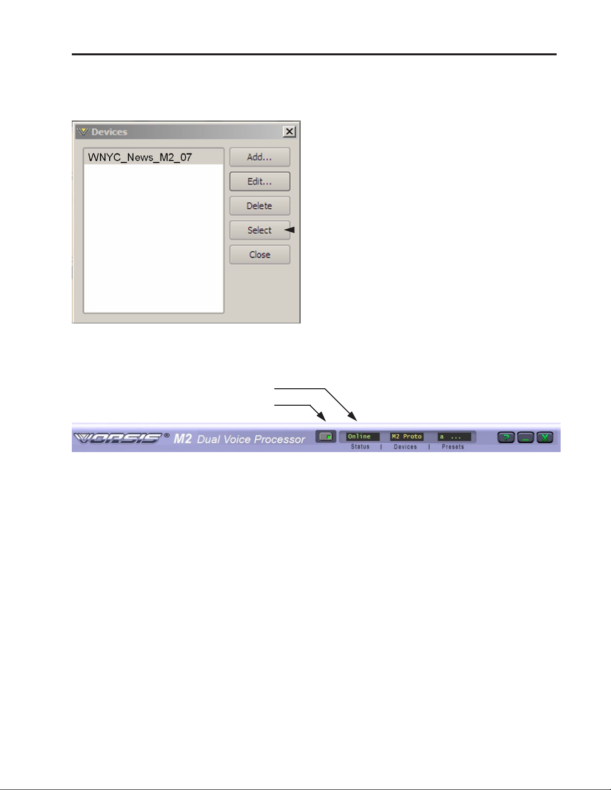
After this is done you may click “OK” on the Edit Device box. Then, in the Devices
Dialog box highlight (single left click) the
M-2 device that you just added (shown
highlighted in the image on the left) and
click on “Select.”
This step tells the GUI specically which
M-2 you want to connect to.
Next, click on the Online/Ofine button just to the left of the Status indicator, unless
the button’s green indicator is already lit.
Status Display
Online/Ofine Button
In the Status window you may see the message “Trying” as the GUI is handshaking
with the M-2. Once the handshake is complete and communication protocols are locked
in the Status message should revert to “Online.” The device’s name will show up in the
Devices display.
If for some reason the GUI cannot connect with the M-2, the “Trying” status message
will remain and will occasionally blink as the GUI retries the establishment of a connec-
tion. Under these circumstances the conguration of the GUI and M-2 should be carefully
examined to ensure that the destination TCP/IP address is consistent between the two.
Once these steps are complete you are now ready to use the M-2 from anywhere in
the world through its advanced Graphical User Interface.
M-2 / Oct 2009
Read Me! - page 5
Page 9

CONTENTS
M-2 Digital
Multiband Dual Voice
Processor Technical Manual
Table of Contents
Chapter 1 - General Information
Introduction ....................................................................................1-2
Pre-Installation Notes ....................................................................1-3
Rear Panel Connections ...............................................................1-4
Microphone Inputs .....................................................................................................1-4
Outputs .......................................................................................................................1-5
Remote Control Ports .................................................................................................1-5
Optional GP-4S Mic Control Panel..........................................................................1-6
Remote ON, OFF, Cough .........................................................................................1-6
On and Off Tallies ....................................................................................................1-6
General Purpose Interface..........................................................................................1-7
Ethernet Interface .......................................................................................................1-8
XLR Inputs Pinout Drawing ........................................................................................1-9
XLR/RJ-45 Outputs Pinout Drawing .........................................................................1-10
RJ-45 Control/Ethernet & DB-9 GPI Pinout Drawing ................................................1-11
Chapter 2 - M-2 Operating Guide
Remote Interfacing with The Vorsis M-2 GUI .............................. 2-3
Architecture of the GUI .................................................................2-4
Connecting the M-2 and the GUI .................................................. 2-4
With LAN (Local Area Network) ..................................................................................2-4
Without LAN (Local Area Network) .............................................................................2-5
Host PC Requirements ...............................................................................................2-5
Using the GUI ................................................................................. 2-5
Dynamic Display Region ............................................................................................2-6
Frequency-Domain Graph .....................................................................................2-6
Bargraph Metering.................................................................................................2-7
Signal Path Selection ............................................................................................2-7
Control Area Region ...................................................................................................2-8
Input Calibration & Sweepable Filter Set...............................................................2-9
Microphone Preamp Gain .................................................................................2-9
Microphone Phase ............................................................................................2-9
Phase Scrambler ...............................................................................................2-9
Phantom Power ................................................................................................2-10
M-2 / Oct 2009
page Contents – 1
Page 10

CONTENTS
Filters ................................................................................................................2-11
High Pass Filter ............................................................................................2-11
Notch Filter ...................................................................................................2-12
Low Pass Filter .............................................................................................2-12
Downward Expander ............................................................................................2-13
Threshold ..........................................................................................................2-14
Open .................................................................................................................2-14
Ratio .................................................................................................................2-14
Wait ..................................................................................................................2-14
Depth ................................................................................................................2-15
Close ................................................................................................................2-15
De-Esser ..............................................................................................................2-16
Threshold ..........................................................................................................2-17
Frequency .........................................................................................................2-17
Attack ...............................................................................................................2-17
Bandwidth ........................................................................................................2-17
Release .............................................................................................................2-18
Enable ...............................................................................................................2-18
Compressor ..........................................................................................................2-19
Drive .................................................................................................................2-20
Low X-Over and High X-Over ...........................................................................2-20
Wideband .....................................................................................................2-20
Two-Band ..................................................................................................... 2-21
Three-Band ...................................................................................................2-21
Threshold ..........................................................................................................2-21
Attack ...............................................................................................................2-21
Release .............................................................................................................2-22
Ratio .................................................................................................................2-23
Lows, Mids, and Highs Trim ............................................................................. 2-23
Output ..............................................................................................................2-23
Swap ................................................................................................................2-23
Enable ...............................................................................................................2-23
Parametric Equalizer ............................................................................................2-24
Swap ................................................................................................................2-25
Enable EQ .........................................................................................................2-25
Final Limiter / Output Levels ...............................................................................2-26
Threshold ..........................................................................................................2-26
Attack ...............................................................................................................2-26
Release .............................................................................................................2-27
Output Level .....................................................................................................2-27
System ................................................................................................................2-28
Passwords ........................................................................................................2-28
Sample Rate .....................................................................................................2-29
GUI Mode .........................................................................................................2-29
Side Bar Region ........................................................................................................2-30
Managing Presets .................................................................................................2-30
Preset Button .......................................................................................................2-30
Library Button .......................................................................................................2-31
File Menu ..........................................................................................................2-31
Edit Menu .........................................................................................................2-32
View Menu ........................................................................................................2-33
Devices Button .....................................................................................................2-35
M-2 / Oct 2009
page Contents – 2
Page 11

CONTENTS
Title Bar Region .........................................................................................................2-37
Status ...................................................................................................................2-37
Devices .................................................................................................................2-37
Network Notes ..........................................................................................................2-37
Accessing Menu Options ..........................................................................................2-38
File Menu Items ....................................................................................................2-38
Hardware Menu Items ..........................................................................................2-38
Software Updates .........................................................................2-39
Appendix
Parameters, Units and Ranges .....................................................A-2
M-2 / Oct 2009
page Contents – 3
Page 12

GENERAL INFORMATION
General Information
Chapter Contents
Introduction ....................................................................................1-2
Pre-Installation Notes ....................................................................1-3
Rear Panel Connections ...............................................................1-4
Microphone Inputs .....................................................................................................1-4
Outputs .......................................................................................................................1-5
Remote Control Ports .................................................................................................1-5
Optional GP-4S Mic Control Panel..........................................................................1-6
Remote ON, OFF, Cough .........................................................................................1-6
On and Off Tallies ....................................................................................................1-6
General Purpose Interface..........................................................................................1-7
Ethernet Interface .......................................................................................................1-8
XLR Inputs Pinout Drawing ........................................................................................1-9
XLR/RJ-45 Outputs Pinout Drawing .........................................................................1-10
RJ-45 Control/Ethernet & DB-9 GPI Pinout Drawing ................................................1-11
M-2 / Oct 2009
page 1 – 1
Page 13
GENERAL INFORMATION
General Information
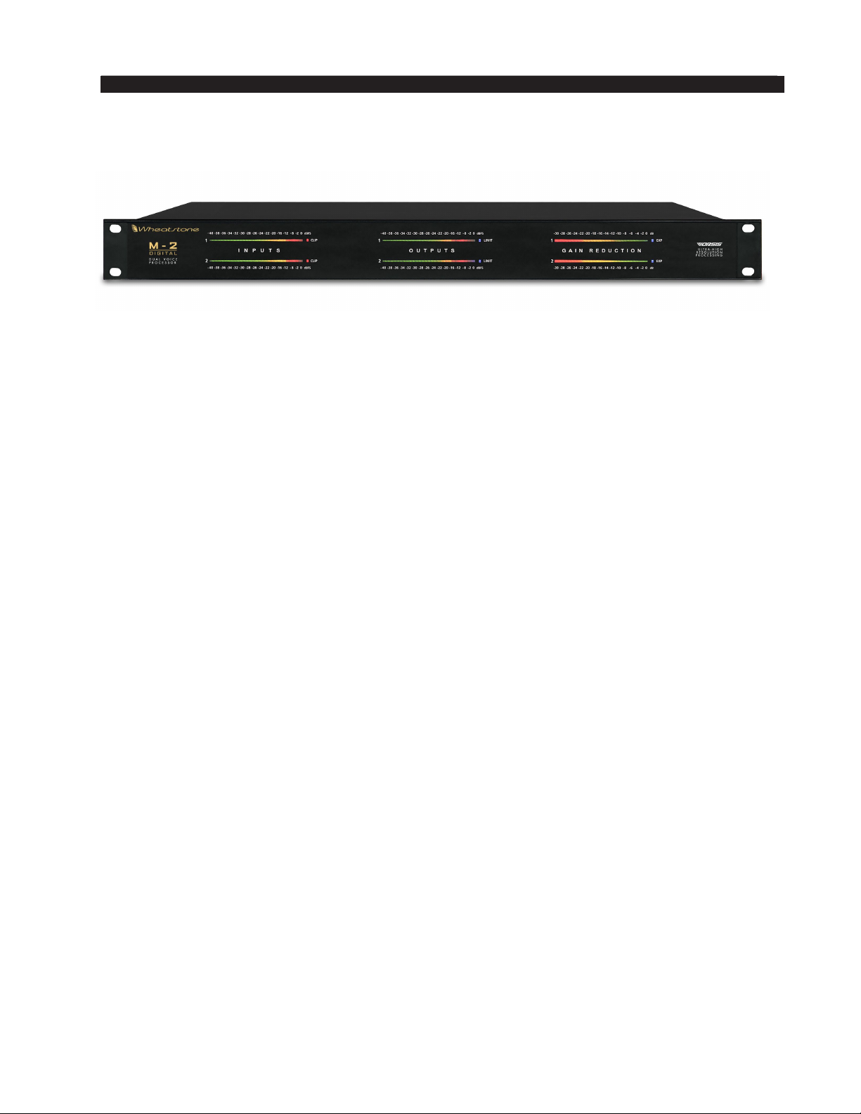
Introduction
The Wheatstone M-2 Digital Dual Voice Processor is a uniquely exible and easyto-use multiband voice processor designed for professional audio applications. It offers
user presets, security, networkability, an all digital and fanless DSP-based framework,
and easy to set up parameters. The unit occupies one 19” wide rack space (height 1 3/4”),
and is 12” deep (not including connectors).
All adjustments of the M-2’s sound are controlled from the remote GUI, enabling
remote control of all parameters. The use of presets allows voice talent to have their own
sound simply at the press of a button. In fact, from one GUI it is possible to control an
entire facility equipped with M-2’s, making multiple Microphone Processor management
easy and straightforward.
The M-2’s hardware includes two channels equipped with very high quality, low-noise
microphone preampliers, four bands of parametric EQ, and Vorsis-designed processing
tools such as de-essers, compressors, and expanders. The unit comes loaded with factory
designed presets, and thanks to the exibility of the software-based GUI designing your
own sound is quite easy.
The electrical specications of the M-2’s microphone preamplier approach the theoretically perfect. Noise within the audio band nudges the theoretical minimum, limited
only by the thermal (Johnson) noise of the precision resistors
is ruler at beyond the extremes of human hearing, and unwanted signal distortions such
as THD, IMD, and TIM are vanishingly low.
Static waveform delity is virtually perfect, affected only by the input high pass and
low pass lters, the phase scrambler when it is in circuit, and any equalization being used.
XLR and CAT5 connectors, which are located on the rear of chassis, make installation very simple.
*
used. Frequency response
*
Thermal noise is intrinsic to all resistors and is not a sign of poor design or manufacture, al‑
though certain types of resistors may have excess noise.
M-2 / Oct 2009
page 1 – 2
Page 14

GENERAL INFORMATION
Pre-Installation Notes
• The M-2 should be mounted in a well grounded equipment rack using at least
two, and preferably four, rack screws. When only two screws are utilized they
must be installed in the two bottom holes in the M-2 front panel rack ears in
order to prevent undue twisting and distortion of the front panel.
• If the M-2 is installed in a rack containing heat generating equipment, particularly when it is installed above such equipment, one rack unit (1 3/4”) blank or
ventilated rack panels should be installed above and below the M-2 in order to
aid natural convection cooling.
• The M-2 should be connected to a source of clean AC power. If local power has
a history of being unstable, it is wise to incorporate an Uninterruptible Power
Source (UPS) in the AC power feed to the M-2
• In facilities with a history of damage or surges from lightning or other sources,
it is wise to incorporate a good quality AC line surge suppressor in the M-2
power feed
*
.
• Audio connections to the microphone inputs should be balanced and made with
a high quality shielded microphone grade cable. The cable shield should be
terminated at both ends of the cable to the XLR connector’s Pin #1. We do not
recommend the use of unbalanced connections at the M-2 inputs.
• As far as signal input polarity is concerned, the XLR Pin #2 is “hot” and the
M-2 does not invert the phase of the audio unless the Invert option has been
selected. (The exception to the above statement is when the Phase Scrambler
is used, which will result in frequency dependent phase shift which causes the
output signal’s phase to be inverted relative to the input signal at certain audio
frequencies.)
*
.
*
As with all computer or microcomputer based digital equipment the M‑2 requires clean
and surge‑free AC power for proper operation. Otherwise unpredictable and hard to identify
issues may arise with its operation and, in the extreme case, even equipment damage or cor‑
ruption of data.
M-2 / Oct 2009
page 1 – 3
Page 15
GENERAL INFORMATION
Rear Panel Connections
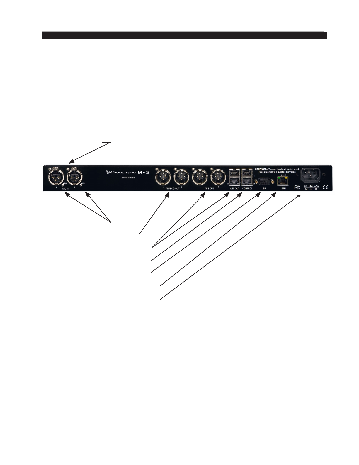
All audio input and output, control, Ethernet, and power supply connections are made
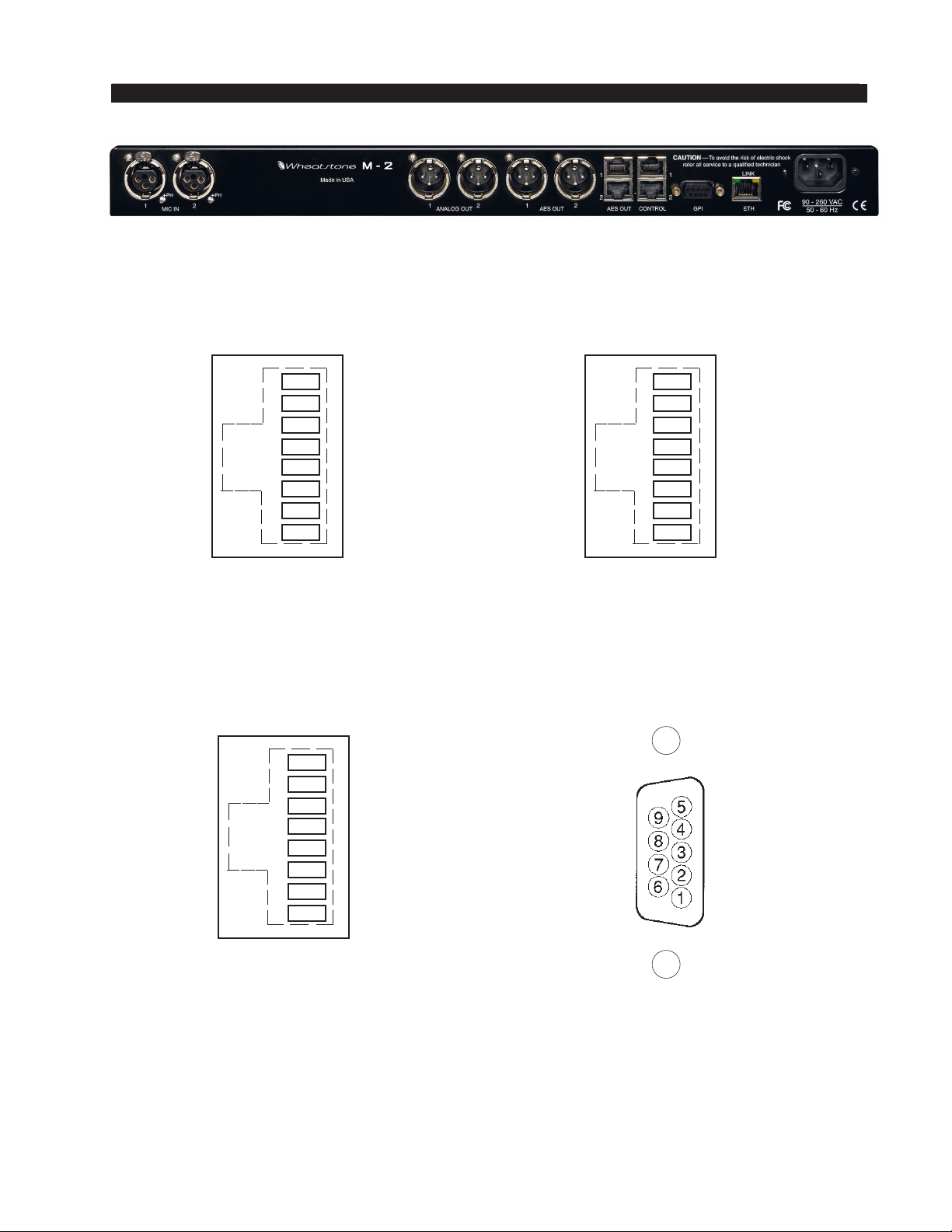
via various connectors conveniently mounted on the M-2’s rear panel. Six XLR connectors are provided: two microphone inputs, two analog and two digital outputs. Five
RJ-45 connectors are also provided; two duplicate the signals appearing at the Channel
One and Channel Two AES output XLR connectors. The others serve as interfaces for
the control and Ethernet connections. The DB-9 connector provides eight GPI inputs
for the most used presets. The pinout drawings on pages 1 -9 through 1-11 summarize
all wiring connections.
Microphone Inputs
Phantom Power
Analog Audio Output
Digital Audio Output
Control Connectors
GPI Connector
Ehernet Connector
Filtered AC Power Input
Microphone Inputs
The M-2 possesses TWO microphone level inputs (-50dBu nominal) fed from the
female XLR connector to the internal microphone preampliers. The microphone preamplier has digitally controlled gain, up to a maximum of 70dB, and displays remarkably
high performance and sonic accuracy. Phantom power is available.
Pin 1 XLR 1 SH – MIC 1 IN SH
Pin 2 XLR 1 HI – MIC 1 IN HI
Pin 3 XLR 1 LO – MIC 1 IN LO
Pin 1 XLR 2 SH – MIC 2 IN SH
Pin 2 XLR 2 HI – MIC 2 IN HI
Pin 3 XLR 2 LO – MIC 2 IN LO
M-2 / Oct 2009
page 1 – 4
Page 16

GENERAL INFORMATION
Outputs
The M-2’s two processing channels’ output signals are available as individual analog
line level (+4dBu, balanced) signals on the two male XLR ANALOG OUT connectors
as well as in digital AES format on the male XLR AES OUT connectors, paralled by
two RJ-45 AES OUT connectors for CAT5 connection.
Channel One/Two Analog Outputs—XLR-M
Pin 1 XLR 1 SH – LINE 1 OUT SH
Pin 2 XLR 1 HI – LINE 1 OUT HI
Pin 3 XLR 1 LO – LINE 1 OUT LO
Pin 1 XLR 2 SH – LINE 2 OUT SH
Pin 2 XLR 2 HI – LINE 2 OUT HI
Pin 3 XLR 2 LO – LINE 2 OUT LO
Channel One/Two AES Outputs—XLR-M &RJ-45
XLR-M
Pin 1 XLR 1 SH – AES 1 OUT SH
Pin 2 XLR 1 HI – AES 1 OUT HI
Pin 3 XLR 1 LO – AES 1 OUT LO
Pin 1 XLR 2 SH – AES 2 OUT SH
Pin 2 XLR 2 HI – AES 2 OUT HI
Pin 3 XLR 2 LO – AES 2 OUT LO
RJ-45
Pin 1 RJ-45#1 – AES 1 OUT HI
Pin 2 RJ-45#1 – AES 1 OUT LO
Pin 1 RJ-45#2 – AES 2 OUT HI
Pin 2 RJ-45#2 – AES 2 OUT LO
Remote Control Ports
The M-2’s “CONTROL” RJ-45 connectors may be used with the (optional) Wheatstone GP-4S Mic Control Panel, or may be wired to a custom interface if desired.
Functions available to each signal processing channel of the M-2 include remote on
and off, cough, and tally.
Control—RJ-45
Pin 1 – DIGITAL GROUND
Pin 2 – COUGH ENABLED (momentary)
Pin 3 – N/C
Pin 4 – OFF TALLY (open collector)
Pin 5 – ON TALLY (open collector)
Pin 6 – REMOTE OFF (momentary)
Pin 7 – REMOTE ON (momentary)
Pin 8 – +5V DIGITAL POWER
M-2 / Oct 2009
page 1 – 5
Page 17
GENERAL INFORMATION
Optional GP-4S Mic Control Panel
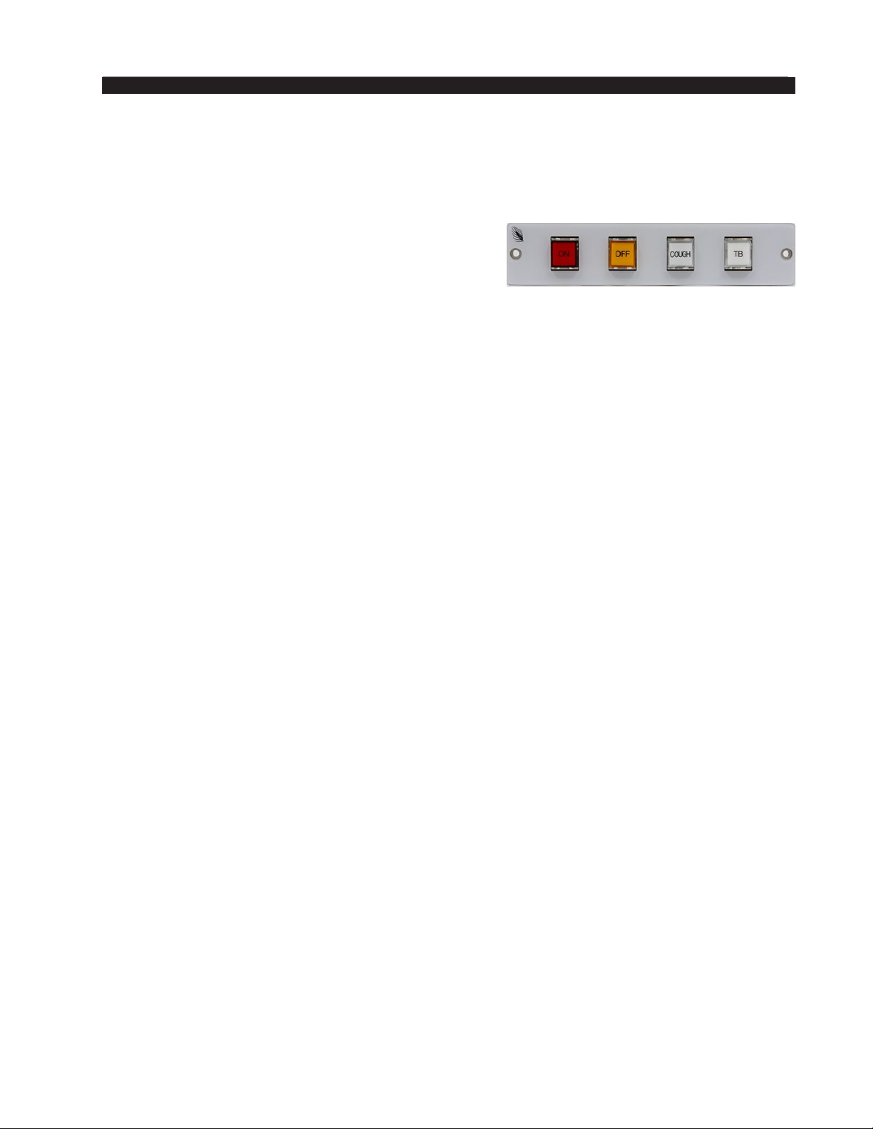
The optional GP-4S panels connect to the M-2 using a standard straight
through CAT5 Ethernet cable of any reasonable length. This panel has “ON,”
“OFF,” and “COUGH” switches for remote control
of the microphone inputs. The “TB” (talkback) button is designed to interact with Wheatstone audio
consoles and has no function in the M-2. The “ON”
and “OFF” buttons are LED illuminated. These
panels can be mounted directly into a furniture
surface or a turret if desired.
To Turn Microphones ON & OFF from a Remote Location
REMOTE ON — When taken low (connected to Digital Ground) activates the
ON TALLY and simultaneously unmutes the M-2 audio output for that channel. You
must provide a momentary closure between Remote On (Pin 7) and Digital Ground
(Pin 1) to latch the microphone audio ON. A user-supplied momentary contact switch
or the optional GP-4S panel is required.
REMOTE OFF — When taken low (connected to Digital Ground) activates the
OFF TALLY and simultaneously mutes the M-2 audio output for that channel. You
must provide a momentary closure between Remote Off (Pin 6) and Digital Ground
(Pin 1) to latch the microphone audio OFF. A user-supplied momentary contact switch
or the optional GP-4S panel is required.
COUGH — When taken low (connected to Digital Ground) temporarily mutes
the microphone for the selected M-2 channel. You must provide a momentary closure between Cough (Pin 2) and Digital Ground (Pin 1) to temporarily mute the
microphone. This is a non-latching mode so the microphone will unmute as soon
as the switch is released. A user-supplied momentary contact switch or the optional
GP-4S panel is required.
On and Off Tallies
ON TALLY — A continuous closure (via open collector) exist between On Tally
(Pin 5) and Digital Ground (Pin 1) whenever the microphone audio is unmuted. This
allows the microphone ON function to also control an on-air light or other “microphone on” indicator at a remote location.
OFF TALLY — A continuous closure (via open collector) exists between
Off Tally (Pin 4) and Digital Ground (Pin 1) whenever the microphone audio is
muted. This allows the microphone OFF function to also control a “microphone off”
indicator at a remote location.
The ON and OFF tallies can be used to control externally powered tally lights
or other functions requiring a continuous closure to function. External tally lights
(such as LEDs) can be powered from the tally output by connecting the external
LED anode to +5V Digital (Pin 8)
*
and the external LED cathode to the On Tally
port (Pin 5) or Off Tally port (Pin 4).
*
An appropriate current limiting resistor must be used so that current drawn from Pin 8
does not exceed 15 milliamps.
M-2 / Oct 2009
page 1 – 6
Page 18

GENERAL INFORMATION
General Purpose Interface
The General Purpose Input (GPI) control port on the M-2 works a bit differently
than in other Wheatstone processors. In the M-2 the eight GPI inputs operate as follows:
- GPI ports 1 through 4 are hard coded to select presets for M-2 Channel One.
- GPI ports 5 through 8 are hard coded to select presets for Channel Two.
The eight separate General Purpose Inputs share a common return. The rear panel
connector is a female DB-9 connector with the following pin assignments. Note that all
pins are isolated from M-2 internal circuitry!
GPI—DB-9
Pin 1 – GPI COM (-)
Pin 6 – GPI 1 IN (+)
Pin 2 – GPI 2 IN (+)
Pin 7 – GPI 3 IN (+)
Pin 3 – GPI 4 IN (+)
Pin 8 – GPI 5 IN (+)
Pin 4 – GPI 6 IN (+)
Pin 9 – GPI 7 IN (+)
Pin 5 – GPI 8 IN (+)
The GPI input circuits are optoisolated by devices having an input/output isolation
of 1,500VAC. These inputs are expected to work very well in high RF environments
and will not cause ground loop issues when connected to external equipment.
Each of the GPI inputs is current limited by a 475 ohm resistance located inside
the GPI control circuitry. The LED device inside the optoisolators is rated at a maximum
forward current of 50mA and a normal operating current of 5mA.
Before connecting external circuitry to the GPI inputs you should rst ascertain whether
it will be necessary to utilize additional outboard series resistance in your application!
The following table will serve as a convenient reference to determine if an external
resistance is required in your application and if so, what value that resistance should be.
Note that in all applications up to and including 48VDC a one-half watt resistor power
rating is sufcient.
Applied Voltage to GPI External Resistance
3.3 VDC None
5.0 VDC 330 Ohms
6.0 VDC 470 Ohms
7.5 VDC 820 Ohms
10 VDC 1.3 kOhms
12 VDC 1.8 kOhms
15 VDC 2.4 kOhms
24 VDC 3.9 kOhms
30 VDC 5.1 kOhms
48 VDC 9.1 kOhms
M-2 / Oct 2009
page 1 – 7
Page 19
GENERAL INFORMATION
Ethernet Interface
The rear panel RJ-45 connector that is assigned to the Ethernet communication
function uses a standard 10/100BaseT interface. It employs both UDP and TCP/
IP protocols to communicate with the remote GUI software running on a host PC
and utilizes common ports to communicate with the M-2.
Ethernet—RJ-45
Pin 1 – TXD +
Pin 2 – TXD Pin 3 – RXD +
Pin 4 – N/C
Pin 5 – N/C
Pin 6 – RXD Pin 7 – N/C
Pin 8 – N/C
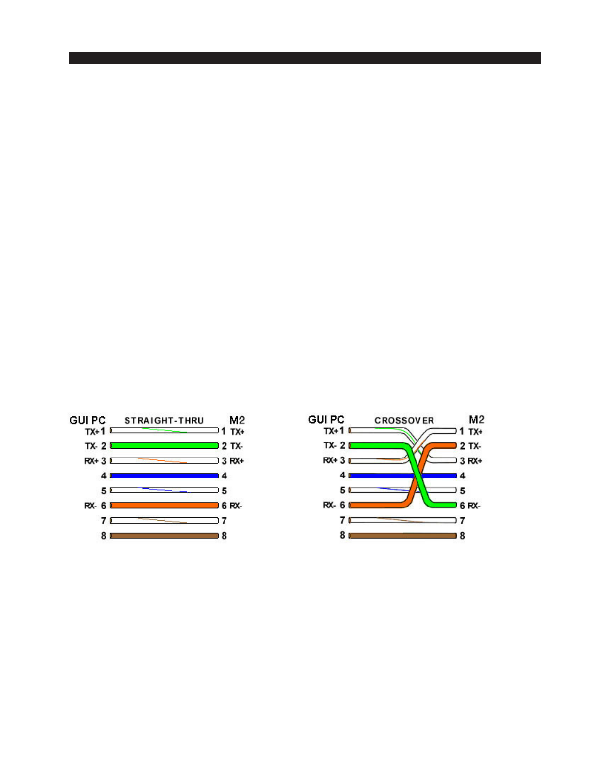
When using the M-2 with a nearby computer and when no local area network
is available, you must use a standard Ethernet crossover cable to interconnect the
computer and the M-2.
When using the M-2 with a remotely connected computer or when it is interconnected to the remote computer via a LAN you must use a standard straight through
Ethernet cable.
Please see the drawing below for the wiring for both straight through and
crossover cables.
In each case the color code for the GUI PC end of the cable is as follows:
1 – White w/Orange tracer
2 – Solid Orange
3 – White w/Green tracer
4 – Solid Blue
5 – White w/Blue tracer
6 – Solid Green
7 – White w/Brown tracer
8 – Solid Brown
M-2 / Oct 2009
page 1 – 8
Page 20
GENERAL INFORMATION
F
X
X
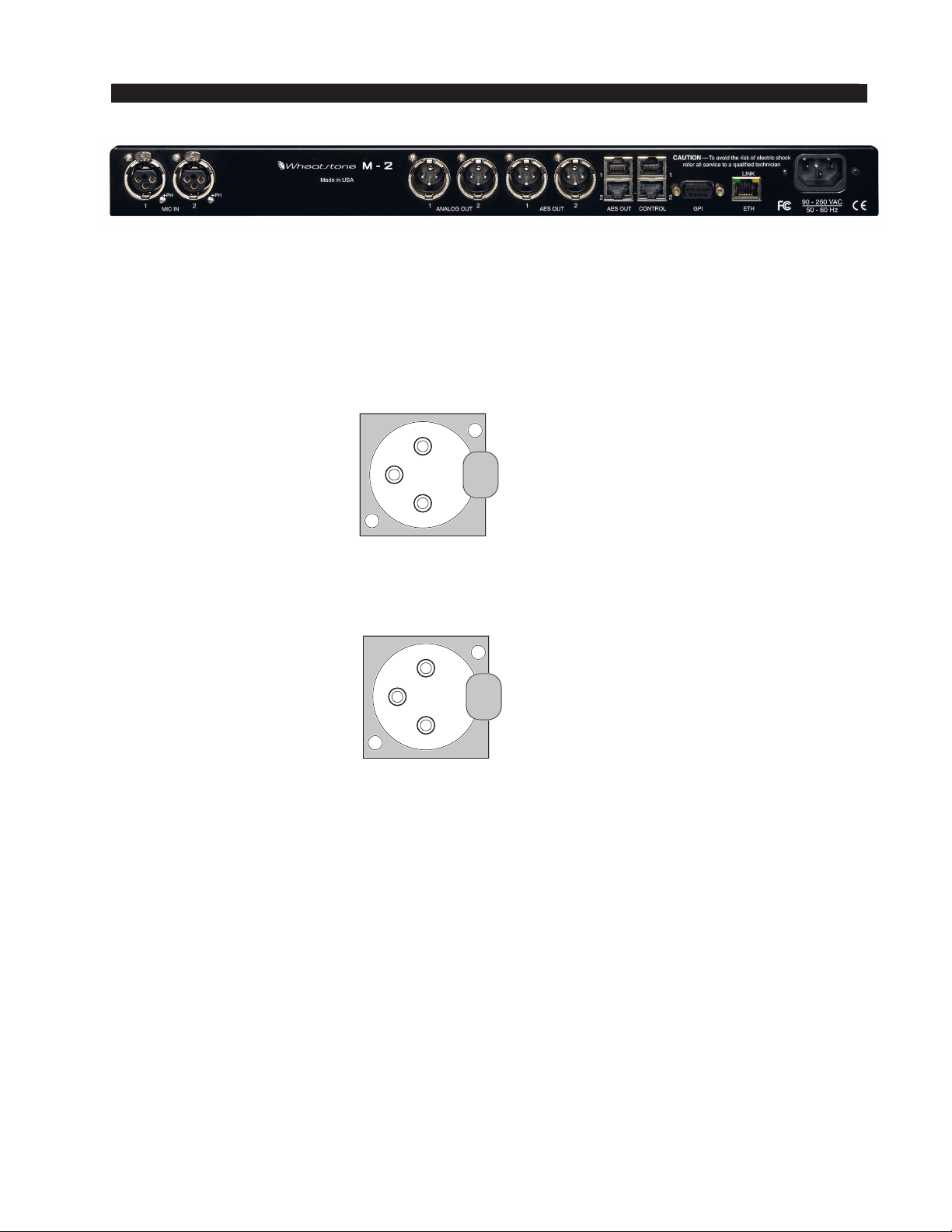
Mic In - XLR-
LR 1-F
LR 2-F
2
3
1
2
3
1
PIN 1 XLR 1 SH - MIC 1 IN SH
PIN 2 XLR 1 HI - MIC 1 IN HI
PIN 3 XLR 1 LO - MIC 1 IN LO
PIN 1 XLR 2 SH - MIC 2 IN SH
PIN 2 XLR 2 HI - MIC 2 IN HI
PIN 3 XLR 2 LO - MIC 2 IN LO
M-2 / Oct 2009
page 1 – 9
Page 21
GENERAL INFORMATION
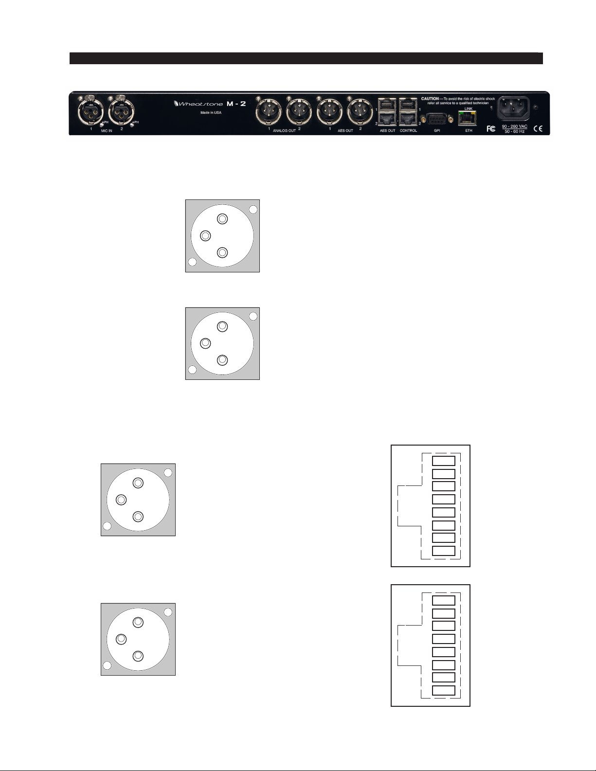
Analog Out - XLR-M
XLR1-M
XLR1-M
XLR2-M
1
3
2
1
3
2
1
3
2
PIN 1 XLR 1 SH - LINE 1 OUT SH
PIN 2 XLR 1 HI - LINE 1 OUT HI
PIN 3 XLR 1 LO - LINE 1 OUT LO
PIN 1 XLR 2 SH - LINE 2 OUT SH
PIN 2 XLR 2 HI - LINE 2 OUT HI
PIN 3 XLR 2 LO - LINE 2 OUT LO
AES Out - XLR-M & RJ-45
PIN 1 XLR1 SH - AES 1 OUT SH
PIN 2 XLR1 HI - AES 1 OUT HI
PIN 3 XLR1 LO - AES 1 OUT LO
RJ-45 #1
1
2
3
4
5
6
7
8
AES 1 OUT HI
AES 1 OUT LO
N/C
N/C
N/C
N/C
N/C
N/C
XLR2-M
M-2 / Oct 2009
1
1
3
2
PIN 1 XLR2 SH - AES 2 OUT SH
PIN 2 XLR2 HI - AES 2 OUT HI
PIN 3 XLR2 LO - AES 2 OUT LO
RJ-45 #2
2
3
4
5
6
7
8
AES 2 OUT HI
AES 2 OUT LO
N/C
N/C
N/C
N/C
N/C
N/C
page 1 – 10
Page 22
GENERAL INFORMATION
Control - RJ-45
MIC 1
RJ-45 #1
Ethernet - RJ-45
ETH
RJ-45
1
2
3
4
5
6
7
8
DIGITAL GROUND
COUGH ENABLED
N/C
OFF TALLY
ON TALLY
REMOTE OFF
REMOTE ON
+5V DIGITAL
MIC 2
RJ-45 #2
1
2
3
4
5
6
7
8
DIGITAL GROUND
COUGH ENABLED
N/C
OFF TALLY
ON TALLY
REMOTE OFF
REMOTE ON
+5V DIGITAL
GPI - DB-9
1
2
3
4
5
6
7
8
TXD +
TXD -
RXD +
N/C
N/C
RXD N/C
N/C
GPI 7 IN (+)
GPI 5 IN (+)
GPI 3 IN (+)
GPI 1 IN (+)
GPI 8 IN (+)
GPI 6 IN (+)
GPI 4 IN (+)
GPI 2 IN (+)
GPI COM (-)
M-2 / Oct 2009
page 1 – 11
Page 23

M-2 OPERATING GUIDE
M-2 Operating Guide
Chapter Contents
Remote Interfacing with The M-2 GUI .......................................... 2-3
Architecture of the GUI .................................................................2-4
Connecting the M-2 and the GUI .................................................. 2-4
With LAN (Local Area Network) ..................................................................................2-4
Without LAN (Local Area Network) .............................................................................2-5
Host PC Requirements ...............................................................................................2-5
Using the GUI ................................................................................. 2-5
Dynamic Display Region ............................................................................................2-6
Frequency-Domain Graph .....................................................................................2-6
Bargraph Metering.................................................................................................2-7
Signal Path Selection ............................................................................................2-7
Control Area Region ...................................................................................................2-8
Input Calibration & Sweepable Filter Set...............................................................2-9
Microphone Preamp Gain .................................................................................2-9
Microphone Phase ............................................................................................2-9
Phase Scrambler ...............................................................................................2-9
Phantom Power ................................................................................................2-10
Filters ................................................................................................................2-11
High Pass Filter ............................................................................................2-11
Notch Filter ...................................................................................................2-12
Low Pass Filter .............................................................................................2-12
Downward Expander ............................................................................................2-13
Threshold ..........................................................................................................2-14
Open .................................................................................................................2-14
Ratio .................................................................................................................2-14
Wait ..................................................................................................................2-14
Depth ................................................................................................................2-15
Close ................................................................................................................2-15
De-Esser ..............................................................................................................2-16
Threshold ..........................................................................................................2-17
Frequency .........................................................................................................2-17
Attack ...............................................................................................................2-17
Bandwidth ........................................................................................................2-17
Release .............................................................................................................2-18
M-2 / Oct 2009
page 2 – 1
Page 24

M-2 OPERATING GUIDE
Enable ...............................................................................................................2-18
Compressor ..........................................................................................................2-19
Drive .................................................................................................................2-20
Low X-Over and High X-Over ...........................................................................2-20
Wideband .....................................................................................................2-20
Two-Band ..................................................................................................... 2-21
Three-Band ...................................................................................................2-21
Threshold ..........................................................................................................2-21
Attack ...............................................................................................................2-21
Release .............................................................................................................2-22
Ratio .................................................................................................................2-23
Lows, Mids, and Highs Trim ............................................................................. 2-23
Output ..............................................................................................................2-23
Swap ................................................................................................................2-23
Enable ...............................................................................................................2-23
Parametric Equalizer ............................................................................................2-24
Swap ................................................................................................................2-25
Enable EQ .........................................................................................................2-25
Final Limiter / Output Levels ...............................................................................2-26
Threshold ..........................................................................................................2-26
Attack ...............................................................................................................2-26
Release .............................................................................................................2-27
Output Level .....................................................................................................2-27
System ................................................................................................................2-28
Passwords ........................................................................................................2-28
Sample Rate .....................................................................................................2-29
GUI Mode .........................................................................................................2-29
Side Bar Region ........................................................................................................2-30
Managing Presets .................................................................................................2-30
Preset Button .......................................................................................................2-30
Library Button .......................................................................................................2-31
File Menu ..........................................................................................................2-31
Edit Menu .........................................................................................................2-32
View Menu ........................................................................................................2-33
Devices Button .....................................................................................................2-35
Title Bar Region .........................................................................................................2-37
Status ...................................................................................................................2-37
Devices .................................................................................................................2-37
Network Notes ..........................................................................................................2-37
Accessing Menu Options ..........................................................................................2-38
File Menu Items ....................................................................................................2-38
Hardware Menu Items ..........................................................................................2-38
Software Updates .........................................................................2-39
M-2 / Oct 2009
page 2 – 2
Page 25
M-2 OPERATING GUIDE
M-2 Operating Guide
Remote Interfacing with the M-2 GUI
A PC application program to control one or many M‑2s is supplied with the
product. It is a Windows
very carefully designed to be intuitive and straightforward in use. The GUI has three
different user levels, levels of complexity if you will, designed to accommodate us‑
ers at all skill levels.
• The ECI or “Expert Control Interface” makes every M-2 control available. It is
intended as a wide open window to the M‑2’s many features and settings ‑ no
controls are hidden from the user.
• The SSI or “Standard Simplied Interface” has been designed for users with
basic familiarity with audio processors but who don’t need to know all the nu‑
ances of what happens under the hood in order to tune up the M‑2 to get the
desired sound.
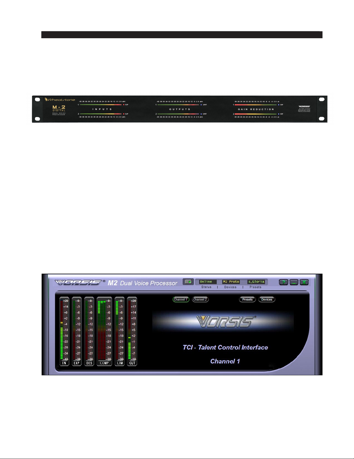
• The TCI or “Talent Control Interface” is designed to be installed on an air studio
PC where the on‑air talent can use it to select the microphone processing preset
that should be in use for their show.
®
Graphical User Interface (GUI) program, which has been
The TCI hides all controls associated with creating and changing the sound of the
M-2. This user interface only allows the selecting of presets and the conguration of
the M‑2 device to connect to.
M-2 / Oct 2009
page 2 – 3
Page 26

M-2 OPERATING GUIDE
The GUI is supplied as a self‑installing program which may be executed from any
directory on the computer. Upon installation, and unless another installation path is
selected, the GUI will install itself under “Program Files\Vorsis\M2” and a “M-2” icon
will appear on the desktop. Double‑clicking on this icon will start the GUI program.
The software is compatible with all recent releases of Microsoft Windows
®
including Windows 2000, Windows XP Home and Professional, Vista, and
Windows 7 operating systems.
The GUI is designed to operate a virtually unlimited number of M‑2 microphone
processors. Each M-2 unit is associated with its own static TCP/IP address as is the
controlling PC. Remember that in most networks the address xxx.xxx.xxx.255 is a
reserved broadcast address and should never be used for conguring network devices.
Since all the M-2’s to be operated by a single GUI must be congured with
TCP/IP addresses within the same subnet, the number of devices “reachable” by the
GUI is limited by the subnetting scheme used.
It is possible to remotely operate any number of M‑2 processors if the network,
the M-2’s, and the GUI PC’s are all congured appropriately according to accepted
networking standards.
It is also possible to operate the M‑2 via a variety of available wireless protocols
and hardware. Given the current state of ux of wireless technology we will leave it
up to the ingenuity of the end user to design and implement the best way to operate
the M‑2 wirelessly in their particular environment.
To congure the M-2 network connection a basic familiarity with Windows naviga‑
tion techniques is assumed. If terms such as “left-click,” “right-click,” “double-click,”
and “drag-and-drop” seem alien, operating the M-2 GUI could be problematic.
Architecture of the GUI
The M‑2 GUI allows you to control and view how the M‑2 is reacting to the audio
passing through it, and do it in real time. It also allows you to make changes to the
processing while viewing the signicance any change is having on the audio.
Connecting the M-2 and the GUI
With LAN (Local Area Network)
The M‑2 and a Windows® PC running the M‑2’s GUI program can be connected
over a standard Ethernet Local Area Network (LAN).
Once the M-2 is installed, powered-up, and veried to be operating normally, a
CAT5 cable connected to a 100baseT LAN should be inserted into the appropriate
socket on the rear panel. Likewise, the GUI should be installed on the desired PC that
has been veried to be working correctly with the LAN.
M-2 / Oct 2009
page 2 – 4
Page 27
M-2 OPERATING GUIDE
Without LAN (Local Area Network)
It is also possible to work without a LAN by connecting the M-2 and the PC
Ethernet ports together using a standard Ethernet crossover cable.
Host PC Requirements
Constraints for the host PC are not extraordinary – it should preferably be at
least 1GHz in speed and the screen resolution at least 1024 x 768 pixels. The LAN
should be 100baseT (100MHz) capable. Any recent Windows operating system is
quite sufcient.
Using the GUI
The GUI screen may be maneuvered around the computer’s screen by left‑click‑
ing-and-dragging the GUI near the “Vorsis” logo at the upper left of the application
screen. In true “Windows” fashion, the GUI may be minimized (taken off the screen)
and closed by way of the familiar controls at the extreme top right.
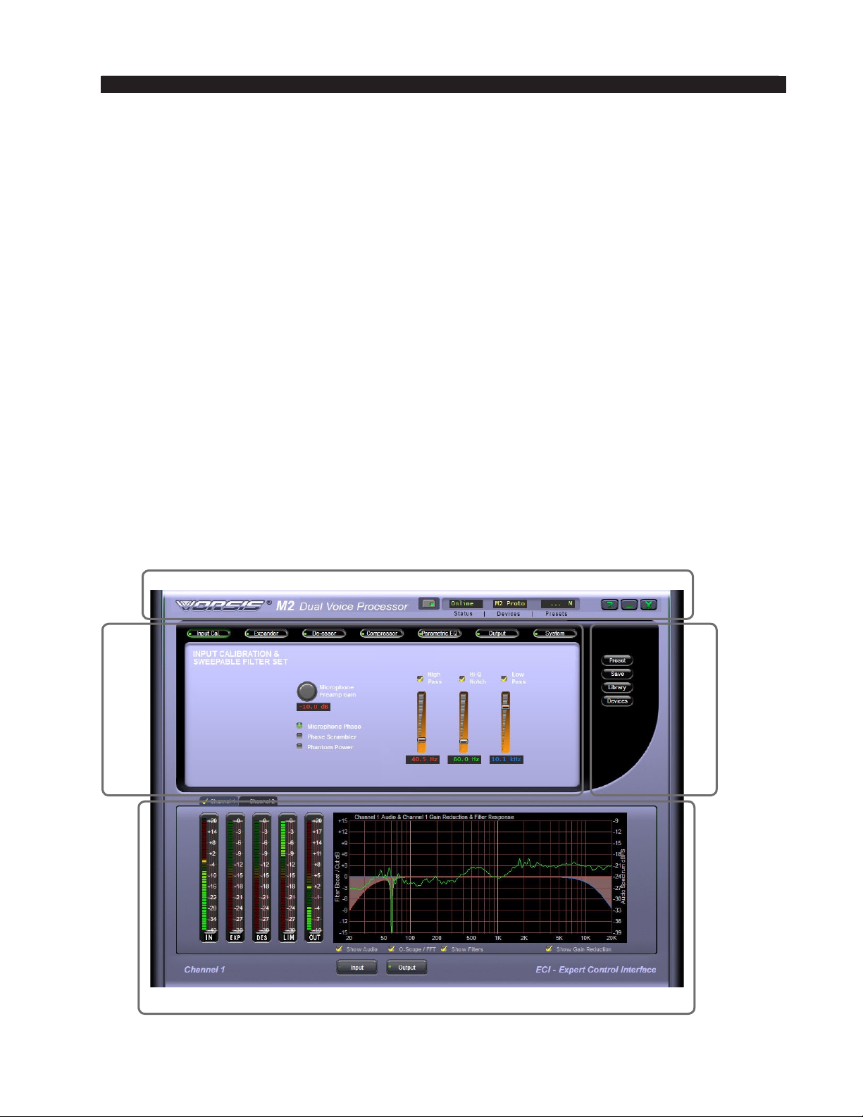
Description of the features and functions of the GUI will follow different discrete
regions of the screen. It will begin with the most eye‑catching region containing the
Dynamic Displays. The Control Area will be covered next, followed by the Side Bar
buttons, and winding up with the Title Bar and Menus.
AREA
CONTROL
TITLE BAR
SIDE BAR
M-2 / Oct 2009
DYNAMIC DISPLAYS
page 2 – 5
Page 28
M-2 OPERATING GUIDE
Dynamic Display Region
Frequency-Domain Graph
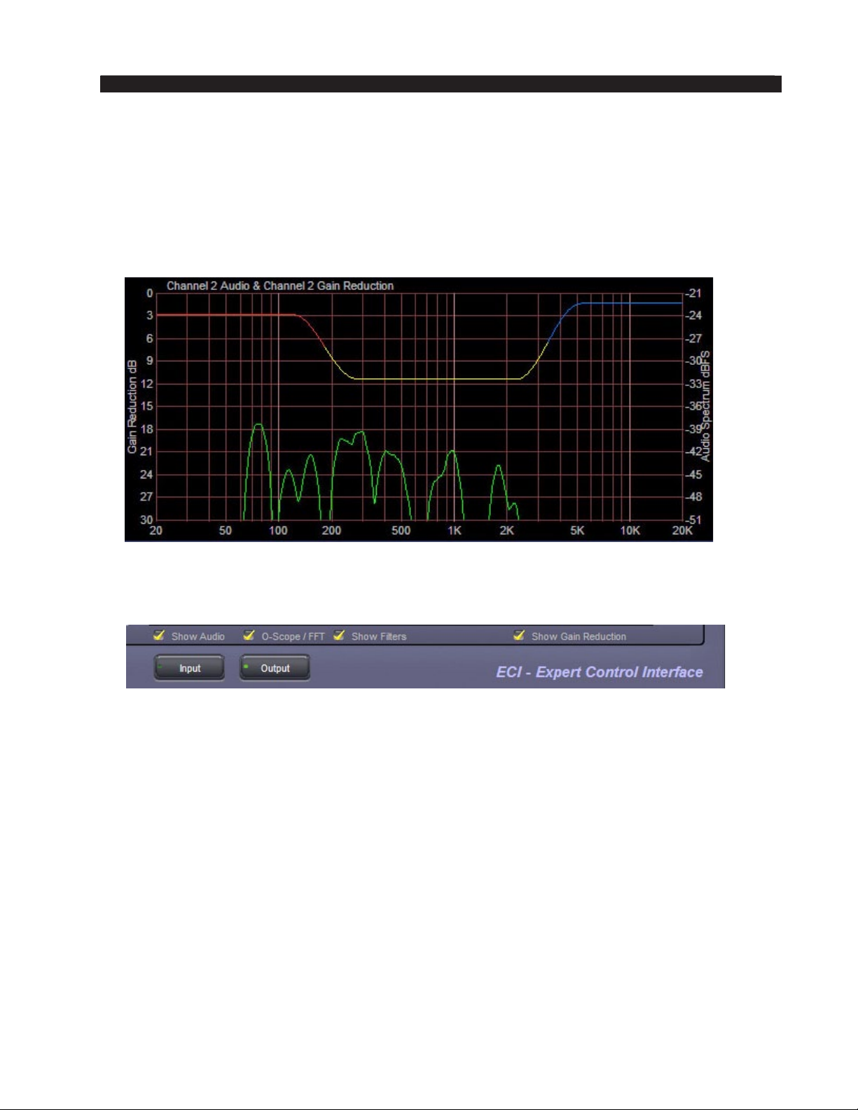
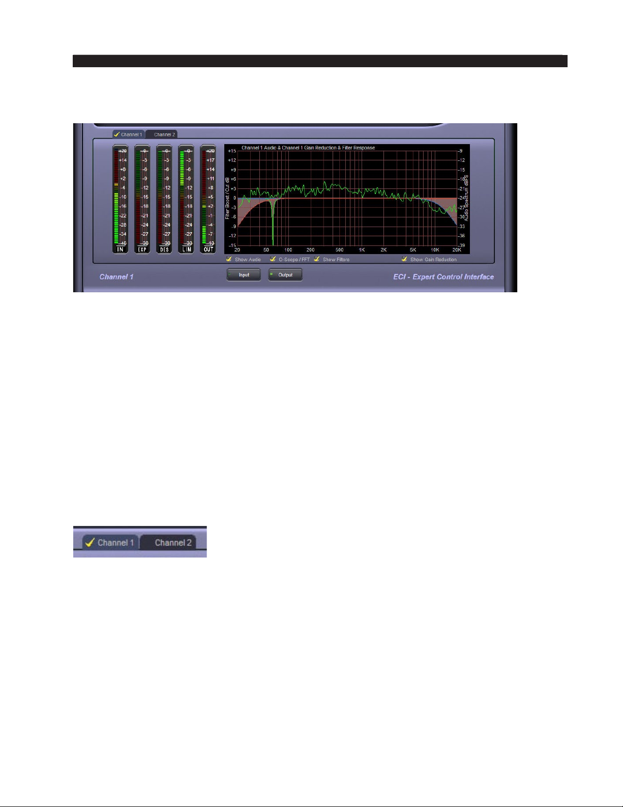
Visually, the most interesting and useful element on the main screen, and dominating
the lower half of both the ECI and SSI versions of the GUI, is a large graphical display
logarithmically depicting the standard audio frequency range of 20Hz – 20 kHz. The verti‑
cal axis scale may be altered by clicking and dragging the scale up or down. The overall
displayed vertical range remains at 30dB, with gradations every 3dB.
Along the bottom of the large graphical area is a row of four small checkboxes for
enabling different views within that display area. When selected or deselected a yellow
checkmark appears and disappears respectively.
Show Audio — When selected (and O-Scope/FFT is unchecked), an FFT (Fast Fourier
Transform) of the audio is displayed in real time showing audio frequency spectra versus
time.
O-Scope (oscilloscope)/FFT — When “O-Scope/FFT” and “Show Audio” are simulta‑
neously selected, the display substitutes a real time amplitude versus time display instead
of the FFT which shows frequency versus time.
Show Filters — When enabled the end user can view how the parametric equalizer,
sweepable lter set, and de-esser’s frequency responses are being affected by the lters
operating in those processing stages.
Show Gain Reduction — When selected, displays the amount of gain control in dB
occurring in the compressor, expander, or de‑esser.
Displayed Signal Selection — Directly underneath the small checkboxes are two large
buttons labeled INPUT and OUTPUT.
When INPUT is selected, the graphical display shows audio presented at the input to
the selected channel of the M‑2. When OUTPUT is selected the graphical display shows
the audio after the M‑2 has processed it. The mode that has been selected is indicated by a
small green “on” light in the selected button.
M-2 / Oct 2009
page 2 – 6
Page 29
M-2 OPERATING GUIDE
Bargraph Metering
To the left of the graphical display area are ve vertical bargraphs, each having a 30dB
vertical display range, except for IN, which has a 60dB range. From left to right they are:
• IN - Displays the channel 1/channel 2 input signal level.
• EXP - Displays the amount gain control occurring within the Expander algorithm.
• DES ‑ Displays the amount of de‑essing when it is occuring.
• LIM - Displays the amount of limiter gain control occurring within the nal limiter
when it is engaged.
• OUT - Displays the channel 1/channel 2 audio output amplitude in dBu.
The level meters are dual-indicating peak-over-average, with peaks riding as a lone “dot”
over a solid bar-graphed average. An “Over” indication is at the top (but slightly distanced
from) the input level bargraphs.
Signal Path Selection
Above the bargraph meters are tabs labeled Channel 1 and Channel 2, that select which
of the two signal channels within the M-2 is being operated upon / displayed.
M-2 / Oct 2009
page 2 – 7
Page 30
M-2 OPERATING GUIDE
Control Area Region
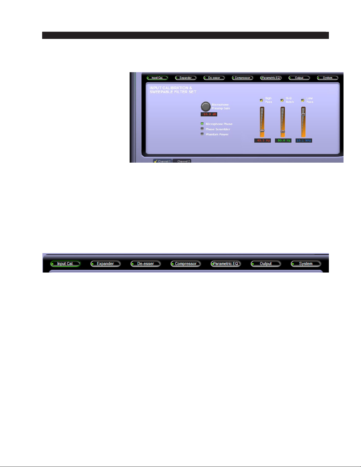
When the GUI software
is in its ECI or SSI modes
the large area above the
graph and meters host the
controls available at those
user levels (note that no
controls are available when
the GUI is in its TCI mode).
To operate the controls
either place the cursor
above the desired control
and use the mouse’s scroll
wheel to “increase” or
“decrease” the control’s
position; or left click on the control, and slide the mouse to move the control ‑ up or
right increases the control’s indicated position, down or left decreases it. The behavior
of the controls can be made ner by holding down the keyboard’s control key (“Ctrl”)
while adjusting, or coarser using shift.
When the GUI software is in its ECI or SSI modes there is a row of buttons across
the upper portion of the GUI corresponding to the various processing sections and in
the signal ow order. A small indicator at the left end of each button indicates if signal
processing within that block is active. Left-clicking a button opens a panel of controls
for that portion of the signal‑processing.
Input Cal. — Displays the controls for the microphone input gains, phase scram‑
blers, phase inversion controls, and phantom power. Gains access to the controls for
the High Pass, Low Pass, and Notch Filters.
Expander — Gains access to the controls associated with the Downward Expander,
noting that the ECI mode has some controls that the SSI mode does not have.
De-esser — Gains access to the controls for the de-esser stage. Like the Expander,
the ECI mode has some controls that the SSI mode does not have.
Compressor — Displays the controls for the multiband voice processing section.
Like the Parametric EQ and Expander the ECI mode has some controls that the SSI
mode does not have.
Parametric EQ — Displays the controls for the four‑band fully parametric equal‑
izer. Note again that the ECI mode has some controls that the SSI mode does not have.
Output — This screen hosts the controls for engaging and using the nal Peak
Limiter as well as the Output level controls.
System — Gains access to settings for security, user level selection, I/O-Settings-
follow‑Presets mode, and output sample rate.
M-2 / Oct 2009
page 2 – 8
Page 31
M-2 OPERATING GUIDE
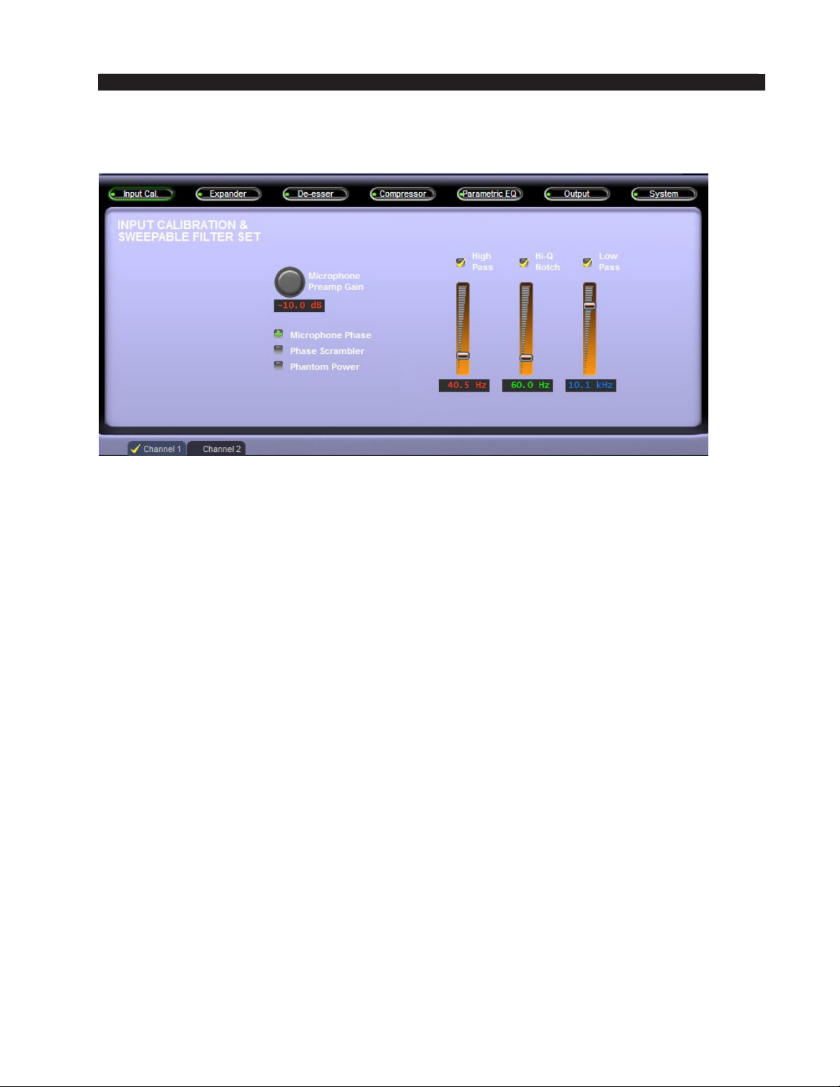
INPUT CALIBRATION & SWEEPABLE FILTER SET
M-2 Input Callibration & Sweepable Filter Set Screen
(Note that the M-2’s two microphone preampliers and associated controls are
accessed using the Channel 1 and Channel 2 tabs shown on the lower left side of
the GUI.)
Microphone Preamp Gain
Each of the two M-2 microphone preampliers is equipped with a gain control
capable of being adjusted to accommodate virtually any microphone and acousti‑
cal environment. The gain controls each have a gain range of 80dB, allowing the
preamplier gain to be adjusted from -10dB (10dB loss) to +70dB in 1dB steps.
Microphone Phase
The electrical phase of each microphone channel may be reversed simply by
clicking on the Microphone Phase checkbox. When the selected M‑2 input is in
phase with the output the checkbox displays a plus sign (“+”). If the signal phase
from input to output has been inverted the box will display a minus sign (“-“).
Phase Scrambler
Each channel of the M-2 is equipped with a fourth order all-pass network which
is designed to rearrange the microphone signal’s phase‑verses‑time alignment of its
harmonics relative to its fundamentals. This results in positive and negative signal
peaks being more equal.
Once the positive‑to‑negative energy distribution is corrected voice signals are
easier to process by later processing, with the end result being an increase in voice
loudness.
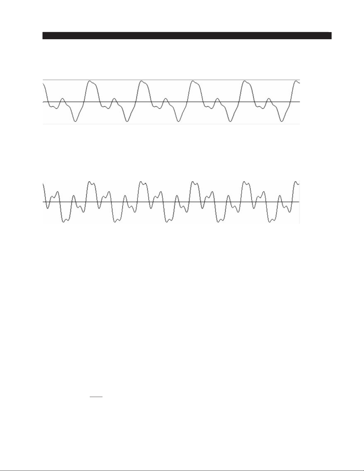
The waveform below is typical of many human voices. Notice how the amount of
signal inside the peaks both above and below the center line is unequal? This means
M-2 / Oct 2009
page 2 – 9
Page 32
M-2 OPERATING GUIDE
that the voice is asymmetrical and can benet from the use of phase scrambling
(or de‑correlation, as it’s sometimes called).
Asymmetrical Voice Waveform
Below is the same voice after processing by the phase scrambler. Notice how
the amount of energy inside the peaks above and below the center line is more
equal? This is what the phase scrambler does… it just “rearranges” energy…
Symmetrical Voice Waveform
It is important to understand that neither the frequency content nor RMS en‑
ergy of the voice waveform are altered by the phase scrambler, nor does it add
any form of nonlinear distortion. It only rearranges the phase relationships of the
signal’s harmonics to its fundamental frequencies.
Phantom Power
The M‑2 may supply phantom power to microphones that require it. To enable
phantom power, two steps may be required.
1. The M‑2 is shipped from the factory with internal jumper J3 set to open.
When this two pin header is open it prevents phantom power from being
applied to the channel 1 or channel 2 microphone input connectors, even
if the logic switch in the input screen of the GUI has been set to enable
phantom power. This jumper provides a protection mechanism for those
installations where only dynamic microphones are used, thereby preventing
potential microphone damage if for some reason the phantom power enable
checkboxes in the GUI are checked.
2. In the Channel 1 and Channel 2 views of the GUI’s Input screen is a phan‑
tom power enable checkbox. When selected (and when the above mentioned
jumper is also in place inside the M‑2) phantom power will be provided to
the microphone connected to the selected channel.
M-2 / Oct 2009
page 2 – 10
Page 33
M-2 OPERATING GUIDE
Filters
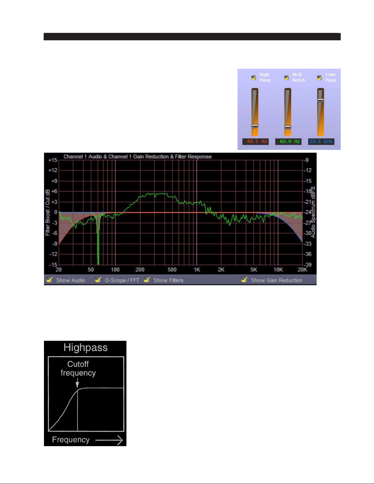
The M‑2 is equipped with an effective set of specialized
and “sweepable” audio lters that can be used to condition
the audio signal prior to further processing. The controls
available in the ECI and SSI GUI’s appear as follows.
When the controls have been set for a particular response
the combined effect of the three controls appears as shaded
curves in the lower graphical area. An example is shown
below. Note that Show Filters must be checked to see the
lter response.
Filter Set - Display of Overall Combined Response
The M-2’s lter set is useful for removing low level hums, hiss, and other ob‑
jectionable noises as well as for creating certain special effects.
High Pass Filter
The High Pass Filter in the M-2 is used to remove
undesired, wideband low frequency sounds such as
rumble and other noises from the incoming audio.
Essentially, a high pass lter removes frequencies
below a certain frequency setting without affecting
frequencies above that setting.
The graphic at left demonstrates what happens to the
audio energy that is below the setting of the Frequency
(cutoff) control.
M-2 / Oct 2009
page 2 – 11
Page 34
M-2 OPERATING GUIDE
Notch Filter
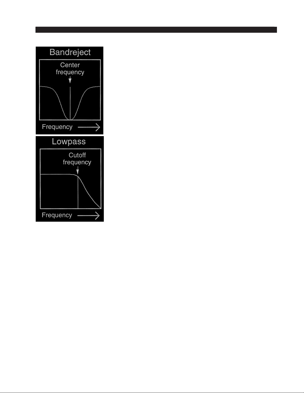
The Notch Filter in the M-2 is used to remove a “nar‑
row” band of frequencies without affecting audio above
and below that frequency.
Essentially, a notch lter is used to remove a single
undesired signal such as a hum, tone, or other fairly nar‑
row signal.
Notch lters are also commonly called Band Reject
lters because the name serves to describe exactly what
the lter does - it rejects a band of frequencies.
Low Pass Filter
The Low Pass Filter in the M-2 is used to remove
undesired, wideband high frequency sounds such as hiss
from the incoming audio.
Essentially, a high pass lter removes frequencies
above a certain frequency setting without affecting fre‑
quencies below that setting.
The graphic on the right demonstrates what happens to
the audio energy that is above the setting of the Frequency
(cutoff) control.
Sweepable Filter Set Example:
Suppose it is desired to make a full bandwidth audio signal sound like it was trans‑
mitted over a telephone. To do this one might set the High Pass Filter to a setting of
about 300 Hz and then set the Low Pass Filter to about 3 kHz. These settings would
remove frequencies below 300 Hz and above 3 kHz, which is a lot like what happens
on a common telephone circuit!
When the ECI or SSI GUI is being used all controls just explained are present in
the Input Calibration screen.
M-2 / Oct 2009
page 2 – 12
Page 35
M-2 OPERATING GUIDE
DOWNWARD EXPANDER
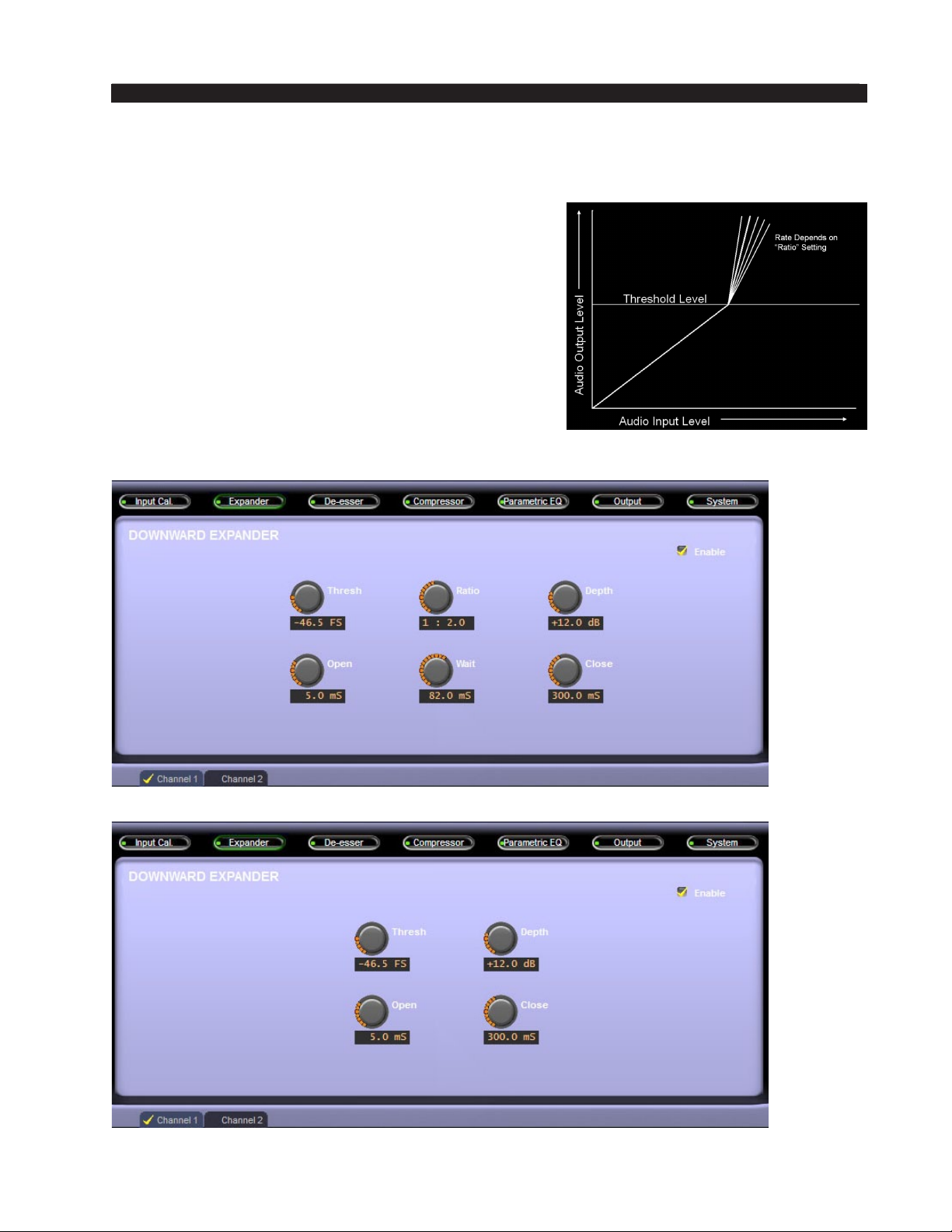
Downward Expanders operate a lot like a compressor turned upside down. What this
means is that unlike a compressor, whose purpose is
usually to make softer sounds louder and louder sounds
softer, an expander is used to make loud sounds louder
and softer sounds softer. In fact an expander can even
be adjusted so that when the audio signal falls below
a certain threshold level, it is turned down to the point
of being completely off if desired.
The graphic on the right shows how the audio out‑
put signal level increases faster than the input level is
rising once audio level has achieved and exceeded the
Expander threshold.
The Expander controls available to the user depend
on the GUI mode. The two screens below demonstrate
this difference.
M-2 / Oct 2009
ECI Mode Expander Screen
SSI Mode Expander Screen
page 2 – 13
Page 36

M-2 OPERATING GUIDE
Threshold
Thresh (or Threshold) adjusts the audio level at which expansion begins. Said
another way, as the audio level into the expander is increasing, nothing happens to
the rate of change of the audio level increasing at the output of the expander until the
threshold is reached. Once that happens, the audio level at the output of the expander
will begin to increase at a rate that is faster than the increase at the expander input.
Open
Once the Expander threshold is reached it begins to take action to increase the
audio level towards the normal unity gain (expanders do not add gain!). How fast it
does this once the threshold is achieved is controlled by the control labeled “Open.”
Think of the Open control as telling the expander how fast to go from an audio
reduced mode to an audio level normal mode.
Faster Open times make sure the expander reacts as soon as an audio signal above
threshold is present. Set too fast and it might open the expander on clicks and pops.
Set too slow and it might clip the rst syllable from a spoken word.
Ratio
The expander’s Ratio control adjusts how aggressively it restores the level to
normal. Lower ratios such as 1:1 don’t do anything. Higher ratios such as 1:6 would
be considered aggressive and might make the operation of the expander audible (or
too audible).
Note that the calibration of the ratio control, such as 1:2, is backwards from that
used with compressors. That’s because, as we explained before, the operation of
an expander is like a compressor turned upside down. So rather than a compressor
allowing a 1dB increase of output level for every 4dB of input level increase (4:1)
the expander does the opposite - it allows (for the same settings) a 4dB increase in
output level for every 1dB increase in input level.
Note: The Ratio control is absent from the GUI when it is in its SSI mode!
Wait
Once the audio level falls back below the expander threshold the expander must
take steps to reduce the audio level according to the Ratio setting as explained above.
However, inaudible operation of an expander usually requires that it wait briey
before starting to decrease the audio gain. This is so that the normal “trailing off”
of speech, such as what happens between sentences or between thoughts, isn’t un‑
naturally chopped off. The wait control then tells the expander how long to hold
the gain normal before starting to reduce it.
If the Wait is set too short the expander might chop off the ends of syllables. Set
too long and it might leave the expander open and expose noises between pauses
in speech that are undesired.
Note: The Wait control is absent from the GUI when it is in its SSI mode!
M-2 / Oct 2009
page 2 – 14
Page 37

M-2 OPERATING GUIDE
Depth
The Expander’s Depth control sets how deeply the gain is reduced when the audio
is below the expander’s threshold. It can be set so that no audible difference is heard
when the expander is above and below threshold all the way to where the audio is
completely turned off when the expander is below threshold.
Depending on the application the control is usually set somewhere between -6dB
and -16dB with 12dB being a very good tradeoff.
If the Depth control is set too aggressively the expander action may become
highly irritating, especially if the speaker is talking in an environment with a high
background noise level.
Close
Once the audio level falls and the expander’s logic decides that it’s time to reduce
the gain, it needs to know how fast you’d like it to do that. The Close control sets that
timing. Faster settings are of course more aggressive and may be audible while slower
settings might leave too much background audio audible for too long.
All of the controls in the expander section are highly subjective as to personal
taste, microphone type, the characteristics of the human speaker, and of course the
acoustical environment.
M-2 / Oct 2009
page 2 – 15
Page 38
M-2 OPERATING GUIDE
DE-ESSER
One of the most important and useful tools in a voice processor is an algorithm to
manage the “esses” in voice, especially when they are excessive. Essentially a de-esser
operates like a dynamic equalizer that automatically restricts the output level within a
chosen frequency range depending on the signal level.
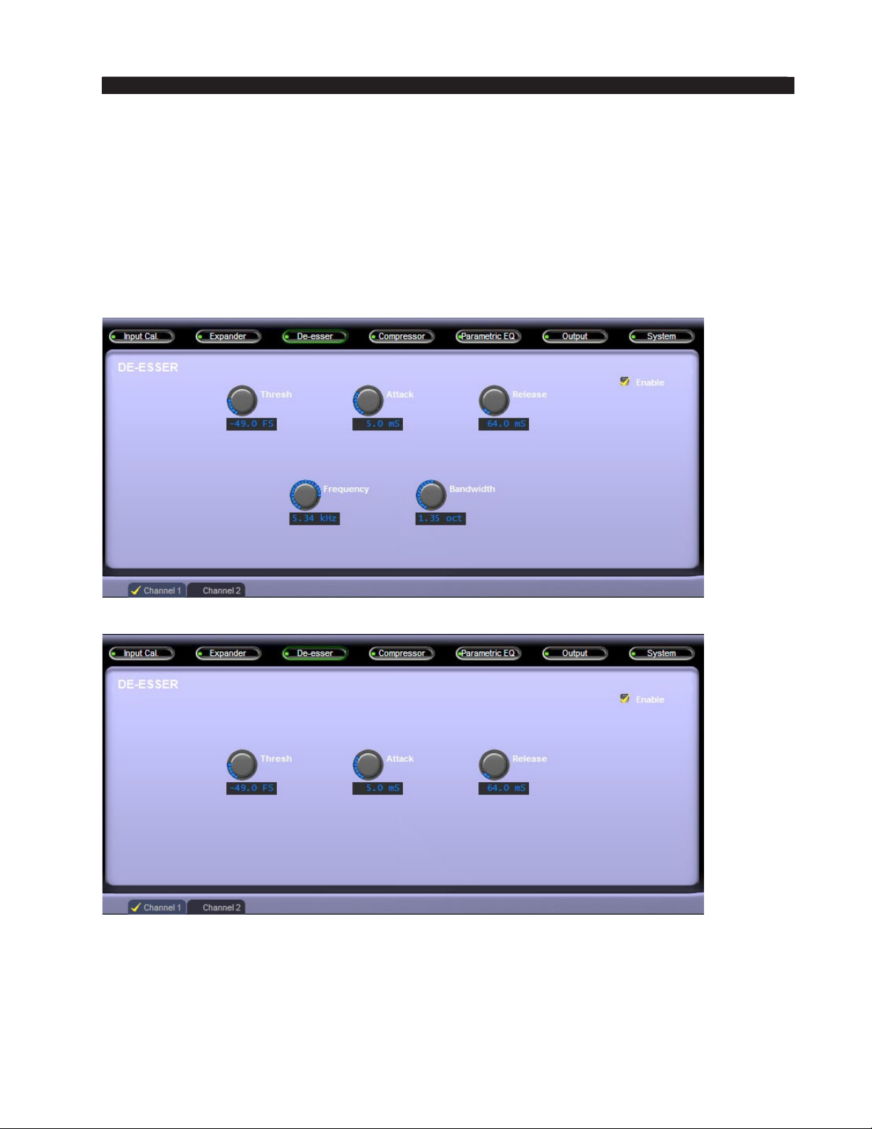
The basic idea is to dynamically reduce the sometimes too‑prominent and objection‑
able sibilant “hissy” noises in speech, particularly when poorly recorded or due to poor
microphone technique. There are ve operating controls involved in the operation of the
de-esser when the GUI is in its ECI mode; three controls are present in the SSI mode.
ECI Mode De-Esser Screen
SSI Mode De-Esser Screen
The only difference between the ECI and SSI modes is the De-esser Frequency and
Bandwidth controls which are present on the ECI mode screen and absent on the SSI.
The SSI mode’s Frequency and Bandwidth values rely on settings recalled from our
Factory presets - settings that were empirically determined through thousands of hours
of collective tuning listening by audio experts.
M-2 / Oct 2009
page 2 – 16
Page 39
M-2 OPERATING GUIDE
Threshold
Threshold is the signal level within the de‑esser’s selected bandwidth (as set by the
FREQ control) at which the de-esser constrains the output level within the de-esser’s
bandwidth. In other words, a signal within the de‑esser’s frequency band will not be
allowed to exceed this threshold level. The threshold is adjustable over the range of
-60dB to -10dB, and controls the amplitude where the de-esser begins to take effect.
Frequency
Adjusts the frequency where the de‑esser is most sensitive. With few exceptions,
most human speech sibilant artifacts fall between 4kHz and 6kHz, although we’ve al‑
lowed the control to be adjustable over the entire 20Hz to 20kHz audio bandwidth so
that it may also be used for special effects.
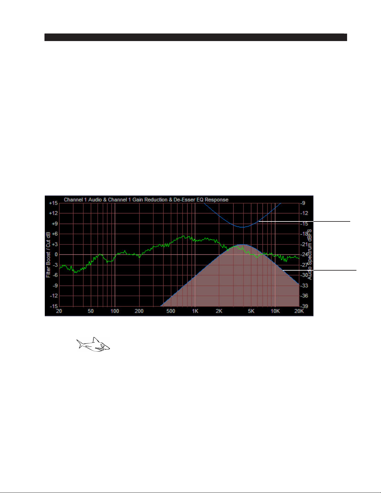
The GUI Frequency control is reected in the Dynamic Display screen as shown
below at the default frequency of 5kHz:
Amount of
De-Essing
Bandwidth of
De-Essing
De-Esser Frequency Display
Attack
Attack, or “attack time,” is the control that determines how fast the de-esser reduces
the gain during the chasing of a sibilant sound in voice. Faster attack times, at least in
many applications, are usually less audible than slower ones, which may under certain
circumstances “punch holes” in the audio - an obvious reduction in output level for a
time longer than was necessary to actually process the event that was being controlled.
Bandwidth
The Bandwidth control adjusts how much of the high frequency spectrum either side
of the “Frequency” setting is affected when the de-esser is in operation. Smaller octave
settings have less effect on adjoining spectrum and larger octave settings affect more.
The nal bandwidth setting is subjective - smaller octave settings are less audible than
larger ones. The nal setting must be arrived at through a short period of experimentation.
M-2 / Oct 2009
page 2 – 17
Page 40

M-2 OPERATING GUIDE
Release
Release, or “release time,” is the control that determines how fast the de-esser
returns the gain to normal after chasing a sibilant sound in voice. Faster release times
are usually less audible than slower ones, and the nal setting is subjective and must
be arrived at through a short period of experimentation.
Enable
When the Enable checkbox in the upper right corner of the
De-Esser screen has a yellow checkmark, the de-esser is in the
signal path. Use this checkbox to toggle the de‑esser in and out
of the signal ow.
M-2 / Oct 2009
page 2 – 18
Page 41
M-2 OPERATING GUIDE
COMPRESSOR
The compressor section in the M‑2 is a descendant of the multiband compressors de‑
signed for the high‑end Wheatstone processors, and is able to operate in a wideband, two,
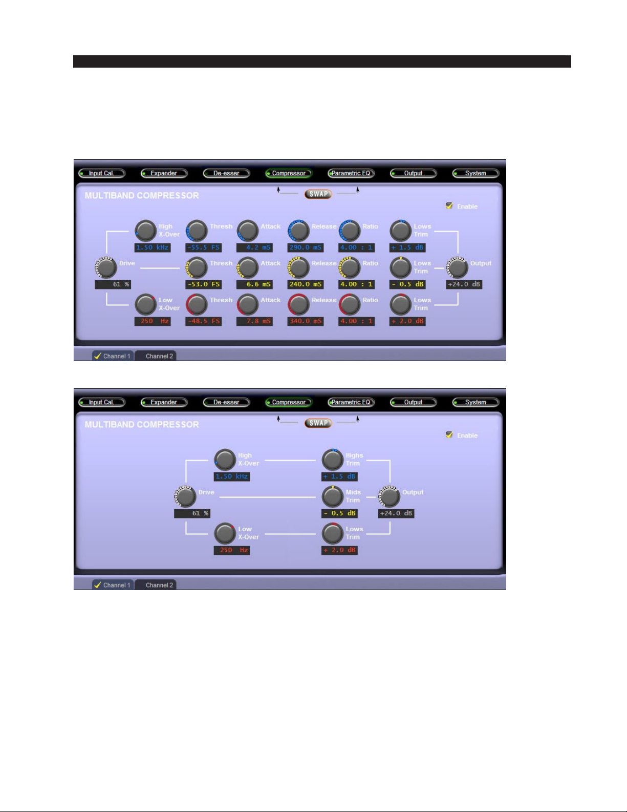
or three band architecture. The graphics below show the compressor screens available
when the M-2 is in either its ECI or SSI modes.
ECI Mode Multiband Compressor Screen
SSI Mode Multiband Compressor Screen
The compressors are “envelope dynamics modiers” that compress the dynamic range
of voice signals, making soft sounds louder and loud sounds softer. With proper adjust‑
ment a compressor can create a consistent output level from a talent’s voice and can do
it subtly - or - it can do it with a lot of “energy” if that is the sound desired. Basically the
compressors allow the overall volume or spectral balance (or both) of the sound to be tai‑
lored exactly to taste when the input level varies as the talent speaks.
The M-2 compressors are special feed forward architectures utilizing Vorsis-designed
program-related dynamics control algorithms. There are only ve main operating controls
for each band (one control each in the SSI mode), plus an Enable switch and the Drive and
Crossover (X-Over) Frequency controls, making compressor operation easy and intuitive.
M-2 / Oct 2009
page 2 – 19
Page 42
M-2 OPERATING GUIDE
The MULTIBAND COMPRESSOR screen of the GUI contains the following
controls:
Drive
The Drive control adjusts how aggressively the compressors will work on the
audio fed to the multiband compressor section. Higher Drive settings increase the
amount of processing while lower settings reduce it.
Low X-Over and High X-Over
These are the controls that set what frequencies will be processed by each of the
M‑2’s three bands.
The way the crossover adjustments work is this:
Frequencies below the Low X-Over setting are processed
by the “low” band, frequencies above the High X-Over are
processed by the high band, and frequencies not processed by
either the Low or High bands are processed by the Mid band.
We’ve made the X‑Over adjustments adjustable over a
very wide range - so much so that the Low Band can be set
as low as 20Hz and the high band as high as 20kHz.
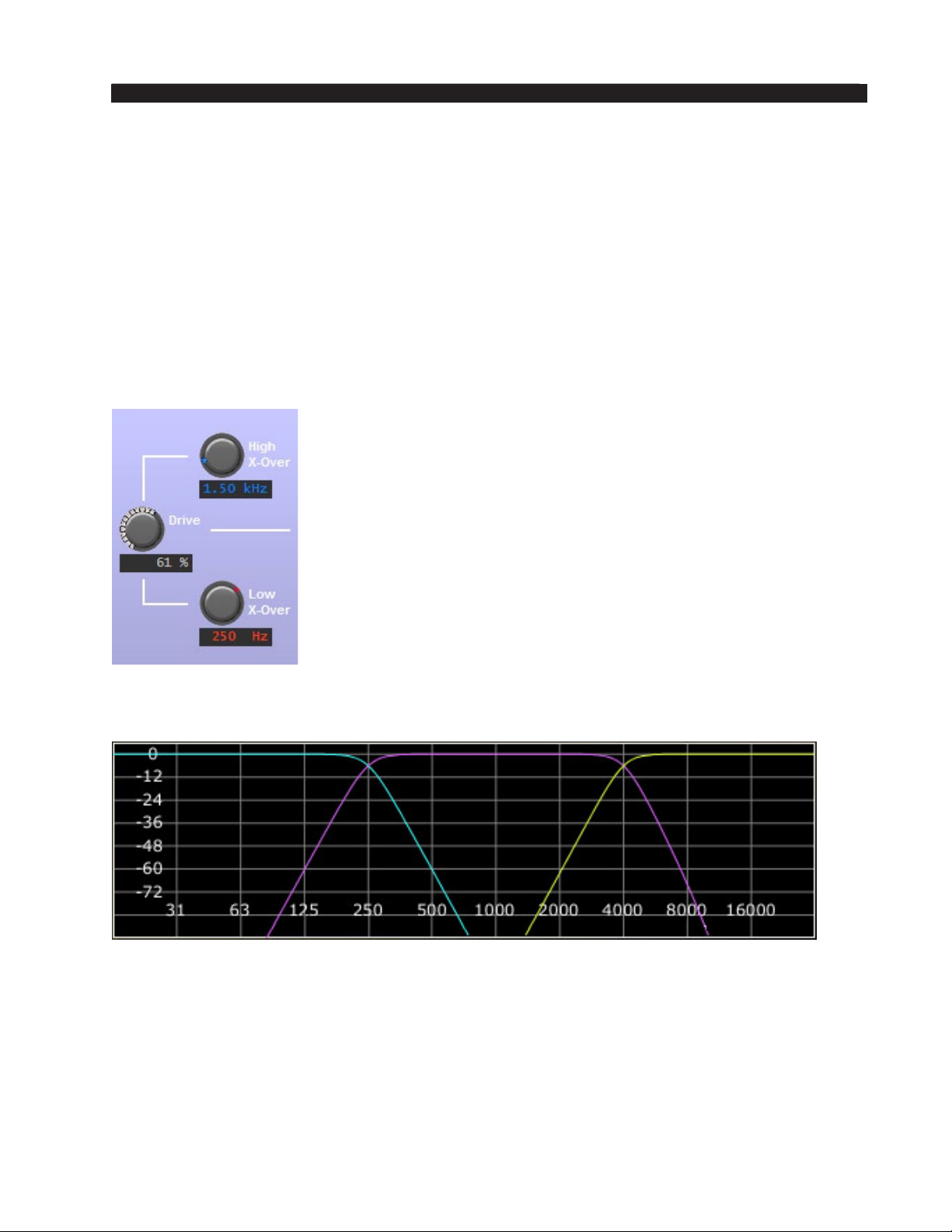
Below is an example of using three-band compression
to make the low vocal frequencies below 250Hz be sepa‑
rated from the midrange energy while also allowing vocal
frequencies above 4kHz to have their energy raised. This
setting would create a warm sounding low end and an airy
high end, especially for male vocals. Female vocals on the
other hand would benet most by moving the Low crossover up to about 400Hz and
lowering the High crossover down to about 2kHz.
Three Band Compression
250Hz and 4kHz Crossover Frequencies
Here are some examples of how this exibility might be used to create a Wide‑
band, Two-Band, and Three-Band Compressor section.
Wideband
Suppose the Low Crossover and the High Crossover has been set to 20Hz and
20kHz respectively. Adjusted this way the M‑2’s compressor becomes a wideband
compressor because all of the audio energy higher than 20Hz and lower than 20kHz
M-2 / Oct 2009
page 2 – 20
Page 43

M-2 OPERATING GUIDE
(all meaningful audio energy within the “human audible” spectrum) is contained
within and processed by the M‑2’s Mid band compressor!
Two-Band
Suppose now the Low Crossover is set to 200Hz and the High crossover remains
set at 20kHz. Now the M-2’s compressor is a two band compressor with a crossover
at 200Hz! The Low band now handles audio energy up to 200Hz and the Mid band
is handling the remainder of the energy between 200Hz to 20kHz.
Three-Band
Now let’s set the Low Crossover to 200Hz and the High Crossover to 1.5kHz. With
these adjustments the M‑2’s compressor is now a full three bands with crossovers
at 200Hz and 1.5kHz! The Low band is handling energy up to 200Hz, the Mid band
from 200Hz to 1.5kHz and the High band from 1.5kHz upward. No other microphone
processor has such exibility!
Why is so much exibility needed in a microphone processor? Simply because
sometimes a little more processing power in the form of automatic equalization is
required. Or, perhaps a special effect is required that simply cannot be achieved
with broadband compression. Static equalization can’t fulll this need either, but
multiband compression can!
Threshold
This is the compressor’s Threshold control which determines at what level the
compressors begin to affect the output signal. Said another way, until the input level
has increased enough to reach the compressor’s threshold setting the output remains
unchanged. Once the threshold is reached the output level is reduced as the input
continues to rise; how much this occurs is a function of the Ratio (discussed later).
Attack
This control determines how quickly the compressor responds to a signal once it
has exceeded the Threshold. The control is adjustable between 0.2 milliseconds and
1 second and is typically adjusted to personal preference. Faster attack times catch
signal peaks more quickly but may make the sound “mushy” by removing transient
detail.
Operation at faster attack times, such as below approximately 10 milliseconds,
causes the compressor to operate more like a peak limiter than an average respond‑
ing compressor. Conversely, slower attack times allow more peaks to escape un‑
controlled, which makes the sound more relaxed. The caveat is that slower attack
times can allow peaks to escape that have the potential to cause headroom problems
further downstream.
M-2 / Oct 2009
page 2 – 21
Page 44
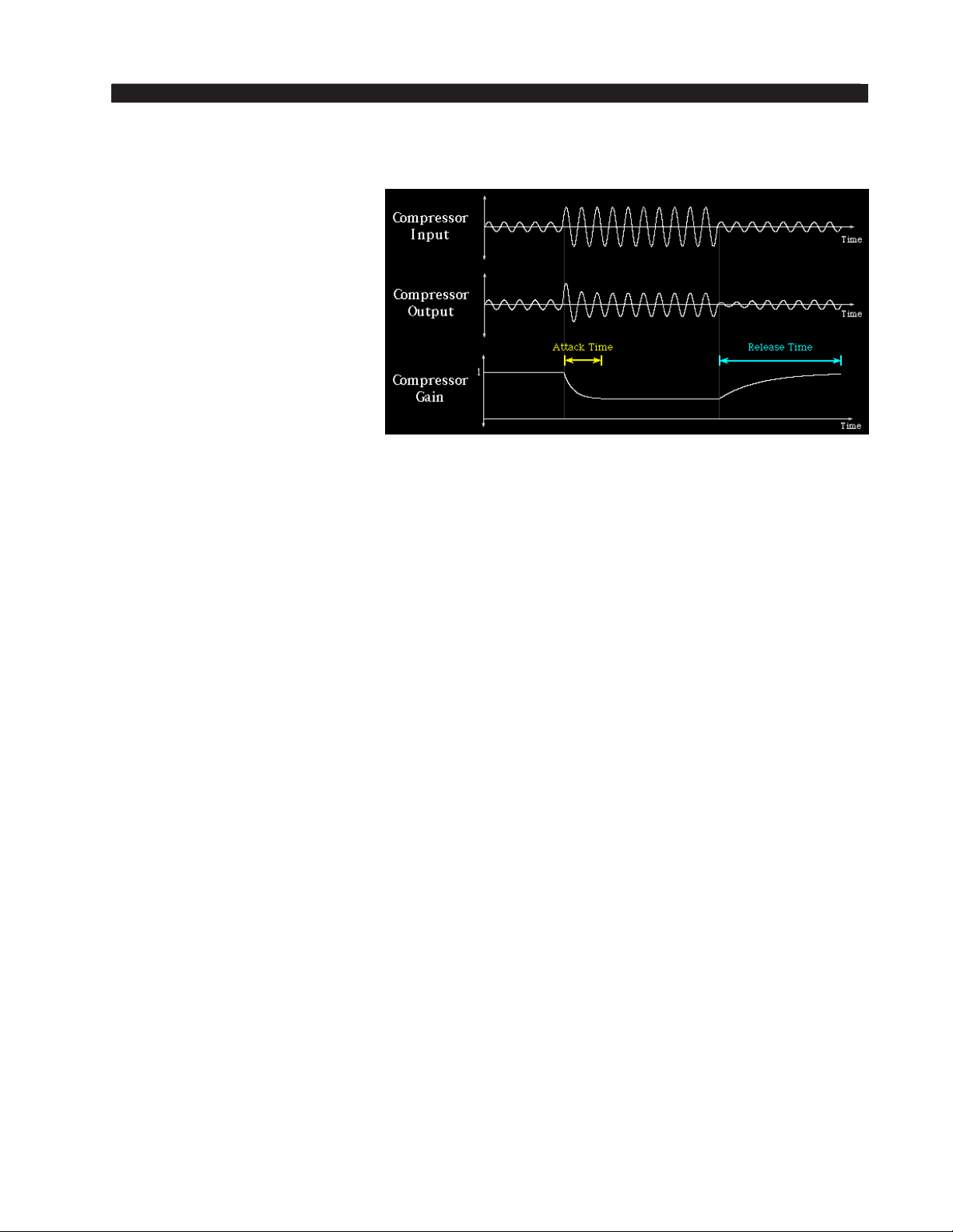
M-2 OPERATING GUIDE
Release
The Release time deter‑
mines how fast the compressor
returns the gain back to normal
after pushing it down while
chasing an audio peak. Refer
to the image on the right to see
how the gain behaves during
the release time phase.
Faster release times in‑
crease the average audio en‑
ergy but can make the resulting
sound “busy” if too fast. Slower
release times make the sound
more natural and relaxed, but
lower the average sound level. Release times in the M‑2’s compressors are adjustable
between 33.0 milliseconds and 1 second.
Compressor Release Time Operating Hint
While the compressor’s Attack time and Ratio are typically adjusted to provide
moderate peak level protection for equipment following the M‑2, the setting of the
Release time control is largely an artistic decision. Please allow us to offer three of the
most common caveats of operating a compressor with extremely fast release times.
• Very fast release times can increase the amount of intermodulation distortion, or
IM. This is because when the compressor release time is set fast enough to “fol‑
low” every cycle of a low frequency signal, the lower amplitude, higher frequency
signals “go along for the ride.” This results in modulation of the high frequencies
by the low frequencies, or what’s known as “intermodulation.”*
• Very fast releases times can exaggerate reverb, whether articially created by
electronic or electromechanical means, or due to the natural early sound reec‑
tions from the hard surfaces of the room where the microphone and voice talent
are located.
• Very fast release times can accentuate the speaker’s breath sounds or other un‑
wanted background sounds that would (should!) otherwise be inaudible.
* The sound of intermodulation distortion ranges from a subtle “thickening” of the
sound, to downright muddy or even “gurgling” at the extreme.
M-2 / Oct 2009
page 2 – 22
Page 45
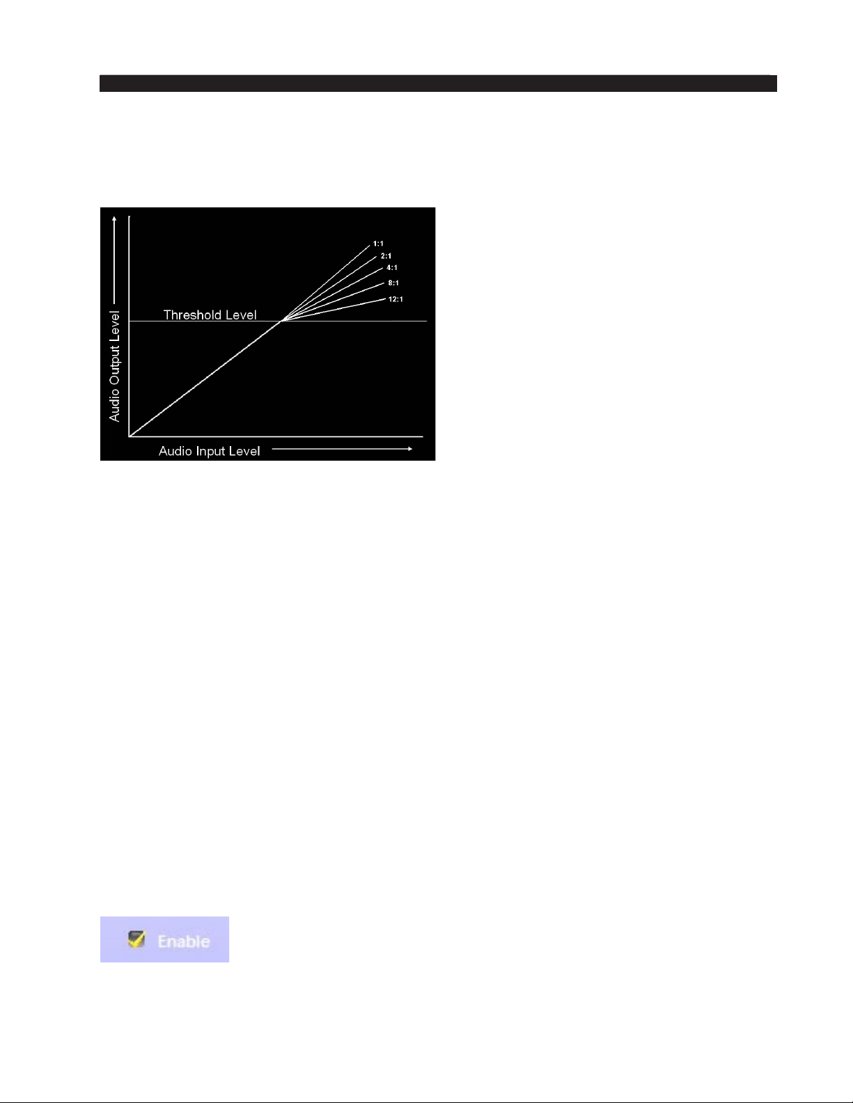
M-2 OPERATING GUIDE
Ratio
The compression Ratio setting controls the steepness of gain reduction once the
audio level has increased enough to reach the Threshold. A ratio of 1 (or 1:1) results in
no compression at all, and at the other
extreme a ratio of 20 (or 20:1) makes
it operate more like a limiter. The ac‑
companying graphic illustrates this.
In the latter case, once the thresh‑
old is achieved the output level of the
compressor will only increase 1dB
when the input level increases 20dB.
The ratio control, while adjusted to
taste, will typically be set somewhere
between 2:1 and 6:1 for most voices.
Special effects may be achieved using
radically different settings.
Lows, Mids, and Highs Trim
After the microphone audio has been processed by the multiband compressor it
is necessary to mix the bands back together again in the proper proportions ‑ this is
what the Trim controls do.
At the output of each compressor band is an adjustable level control that allows
the user to tailor how the bands are mixed back together after compression has been
applied. When the Trim controls are set to the same settings the mix from all three
bands is equal. This will allow a at overall frequency response if the Threshold con‑
trols for all three bands are also set at the same settings. The Trim controls can also
apply EQ effects.
Output
After the three band outputs have been mixed back together using the Trim controls
the Output control sets the overall output level of the compressor section.
Swap
At the top of the Compressor and Parametric EQ control screens is a button labeled
“SWAP.” See the discussion of this button in the PARAMETRIC EQUALIZER sec‑
tion of the manual (page 2‑25).
Enable
When the Enable checkbox in the upper right corner of the
MULTIBAND COMPRESSOR section has a yellow checkmark,
the compressor is in the audio path. When this checkbox is not
checked, the compressor is not in the signal path. The Enable
checkbox toggles this function.
M-2 / Oct 2009
page 2 – 23
Page 46
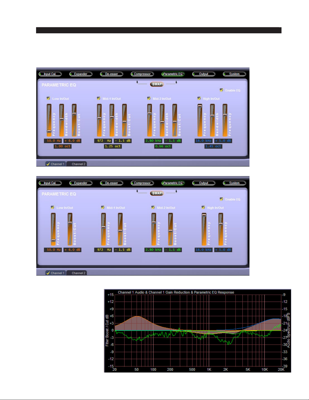
M-2 OPERATING GUIDE
PARAMETRIC EQUALIZER
The adjustment screens for the parametric equalizer as seen in the ECI and SSI
control modes are shown below.
ECI Mode Parametric EQ Screen
SSI Mode Parametric EQ Screen
The graphic on the
right shows how equal‑
izer settings are depicted
in the Dynamic Display
region of the GUI. The
shaded areas show the
response of each equal‑
izer section as well as
the overall combined
response when more
than one equalizer sec‑
tion overlaps.
M-2 / Oct 2009
page 2 – 24
Page 47
M-2 OPERATING GUIDE
Swap
At the top of the Compressor and Parametric EQ control screens is a button labeled
“SWAP.”
This button’s purpose is to allow the user
to interchange the Compressor and Equal‑
izer sections. In one mode the compressor
is prior to the equalizer and in the other the
compressor is after it. Which position of the
Swap mode is used depends on the sound
that the user is trying to achieve.
Placing equalization prior to compression
“preloads” the compressor with whatever equalization curve has been set by the equal‑
izer’s controls. For instance, if boost were applied in the equalizer at a certain range of
frequencies then the compressor will work harder on that band of frequencies.
Likewise, if the equalization is placed after the compressor then whatever curve the
equalizer is set for will be added to whatever frequency response slope is being created
in the compressor by the settings of its Threshold, Ratio and Trim controls.
Each setting of the SWAP control creates a different sound and the user is encour‑
aged to experiment with its setting to see what effect it can create based on the equalizer
and compressor settings being used.
Enable EQ
When this checkbox has a yellow checkmark the equal‑
izer section is switched in. When it is not checked the
equalizer section is not in the signal path. The checkbox
has a toggle action behavior ‑ checking it changes the
state of the EQ IN function.
M-2 / Oct 2009
page 2 – 25
Page 48
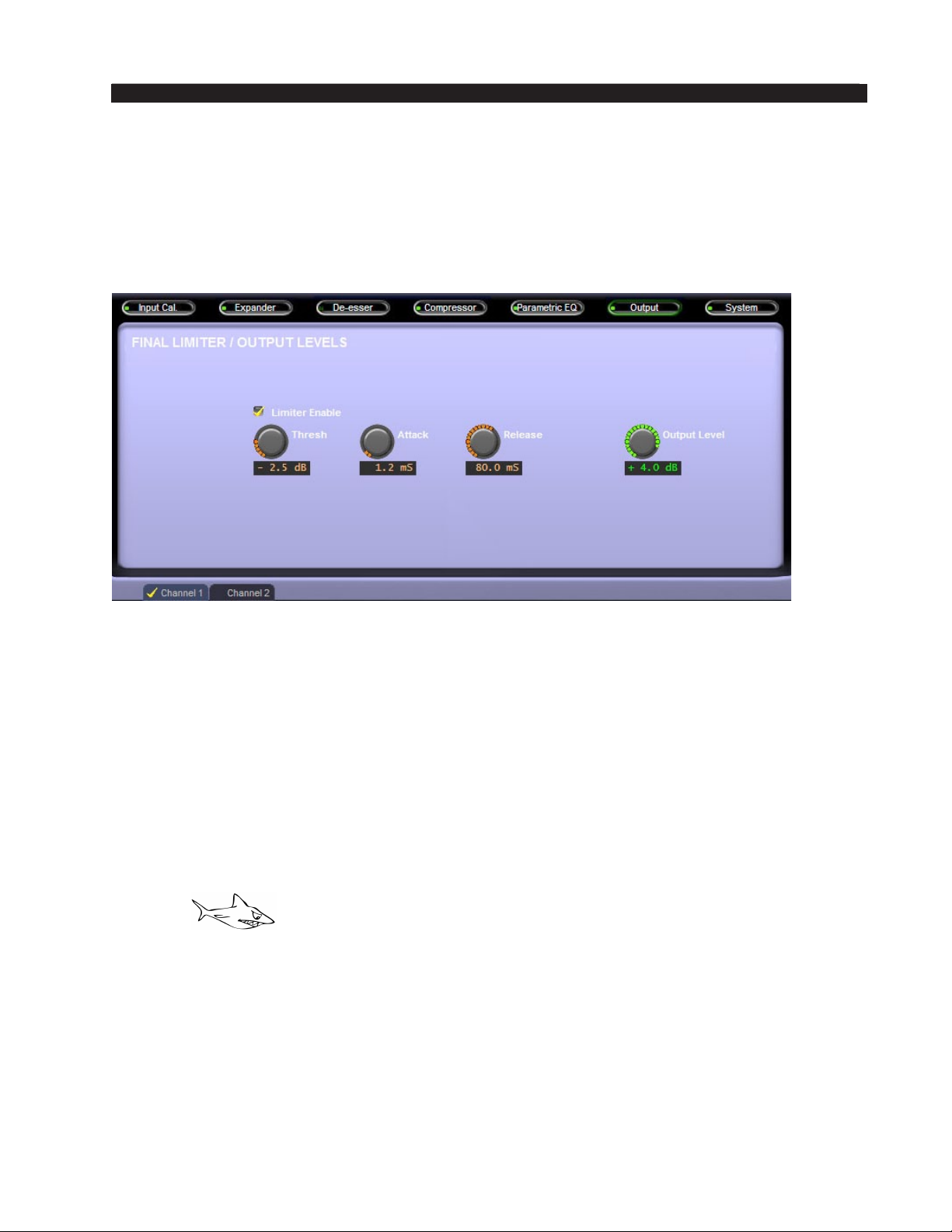
M-2 OPERATING GUIDE
FINAL LIMITER / OUTPUT LEVELS
The output screen contains the controls for the nal limiter stage and the nal out‑
put level control. It also contains the nal limiter’s “Limiter Enable” checkbox that
controls whether or not any limiting work is being accomplished by the nal limiter.
It is not necessary to utilize the nal limiter unless specic limitations are to be placed
on the maximum peak amplitude at the M‑2’s outputs.
Final Limiter/Output Levels Screen
The descriptions for the nal limiter’s controls are as follows, remembering that
each channel of the M-2 has its own nal limiter settings! Access to each signal chain
is by using the Channel 1 and Channel 2 tabs.
Threshold
This control determines at what level the limiter begins to affect the peak output
signal. Said another way, until the input level has increased enough to reach the lim‑
iter’s threshold the output is unchanged. Once the threshold is reached the output level
is constrained to the setting of the Threshold control ‑ no further output level increase
is permitted.
Attack
This control determines how quickly the limiter responds to an audio peak once it
has exceeded the Threshold. The control is adjustable between 0.2 milliseconds and
100 milliseconds and is adjusted to personal preference. Faster attack times catch sig‑
nal peaks more quickly but may make the sound “mushy” and lacking transient detail.
Operation at attack times below approximately 10 milliseconds is usually desired
when there is a need to tightly constrain the peak output level. Conversely, slower at‑
tack times allow more peaks to escape uncontrolled, making the sound more relaxed.
The caveat is that slower attack times can allow peaks to escape that have the potential
to cause problems further downstream.
M-2 / Oct 2009
page 2 – 26
Page 49

M-2 OPERATING GUIDE
Release
Release determines how fast the limiter returns the gain back to normal after pushing
it down after chasing an audio peak. Faster release times increase the average audio
energy but might sound “busy” if too fast. Slower release times make the sound more
natural and relaxed, but lower the average sound level.
Output Level
This control adjusts the maximum output level of the selected M‑2 processing
channel. A separate level control is available for each processing channel by using
the Channel 1 and Channel 2 tabs.
M-2 / Oct 2009
page 2 – 27
Page 50
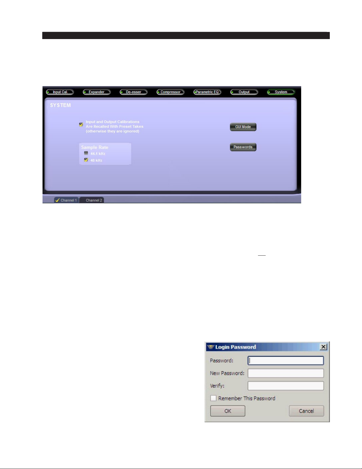
M-2 OPERATING GUIDE
SYSTEM
The M-2’s System screen contains a check box labeled “Input and Output Level Cali‑
brations Are Recalled with Preset Takes” - this is an important concept to understand!
System Screen
M-2 presets ALWAYS store ALL of the settings being used, even the input and out‑
put level calibrations present at the time the preset was saved. By un-checking this box
input and output settings stored within a preset will be ignored when presets are recalled.
On the other hand, if this box is checked, then presets will recall all of the settings
and therefore will (likely) change the input and output level calibrations to whatever
was present when the preset being recalled was last saved.
NOTE: It is unlikely that our Factory presets will have the perfect input and output
settings for your application. Therefore if you like a particular factory preset and wish
to use it often then you should resave it under a new name after the input and output
level settings have been nalized for your application. This will ensure that even if the
checkbox is inadvertently selected the input and output levels won’t surprise you when
your preset is recalled.
Passwords
Functional only when the GUI is online with
the M‑2, this button is used to access the Passwords
security menu for the setting of passwords to restrict
the level of user access to certain functions and
controls of the M-2. Clicking “Passwords” brings
up the Login Password dialog box. To change the
password you must enter the old password, then
enter the new password, and then enter the new
password a second time to verify. If you don’t want
the M‑2 to be password protected, leave both the
New Password and Verify Password boxes blank.
Check the “Remember This Password” box only if
are sure no unauthorized person will use your computer.
M-2 / Oct 2009
page 2 – 28
Page 51
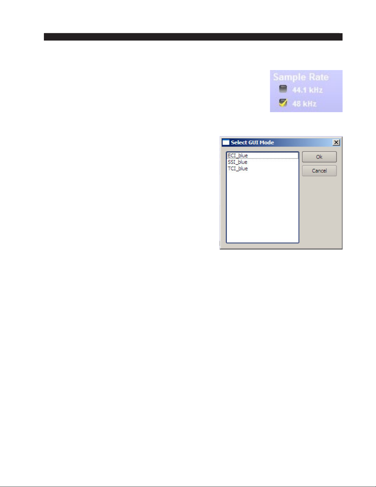
M-2 OPERATING GUIDE
Sample Rate
The M-2’s AES3 digital outputs can be congured to operate
at either 44.1kHz or 48kHz sample rates and the controls used for
conguring the M-2’s digital outputs are found in the System screen.
These controls adjust the sample rates for both the Channel 1 and
Channel 2 ‑ the rates cannot be set independently.
GUI Mode
As we have mentioned previously there are three
“user levels” available for the M-2 that the end user
can choose from:
• ECI, or Expert Control Interface;
• SSI, or Standard Simplied Interface;
• TCI, or Talent Control Interface.
The ECI provides all controls - nothing is hidden.
The SSI interface provides basic controls more easily
understood by less advanced users. The TCI provides
an interface for air talent so they can change presets
but not make any processing adjustments.
Please see Application Note AN2009-02 (on the Wheatstone Processing web
site under “Resources” tab) for how the security properties of the M-1 and M-2
product’s TCI Interface can be tightly restricted in order to prevent certain kinds of
changes by curious air talent.
M-2 / Oct 2009
page 2 – 29
Page 52
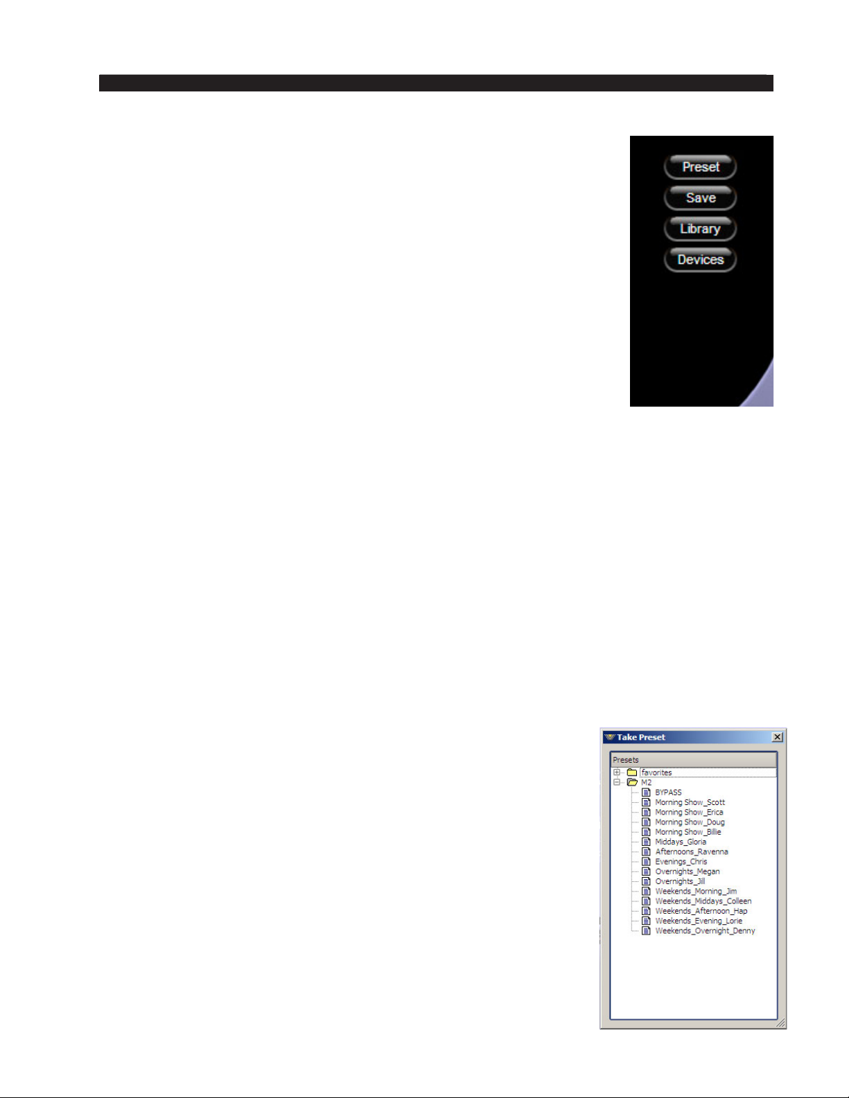
M-2 OPERATING GUIDE
Side Bar Region
To the right of the control area is a vertical row of four buttons. We
will begin by discussing presets and their management, which involves
three of the buttons. We’ll defer a deeper discussion of the “Devices”
button to the very end of this manual section, after presets have been
thoroughly covered.
Managing Presets
Let’s begin with a simple denition:
A preset is a snapshot of all the settings of the M‑2. It is desirable
in many situations to have a library, or collection, of presets so that we
can accommodate different audio processing needs at different times. As
your library of presets grows, preset management (i.e., having presets
arranged so that you can nd the one you need as quickly as possible)
is a major concern.
Several tools are implemented within the M-2 GUI to make your
preset managing life easier. We will navigate the discussion of the sidebar buttons,
dialog boxes, and preset management philosophy in a way that will, hopefully, help
you to get the most out of your M‑2 presets.
The M-2 comes with a variety of Factory Presets which are very good starting points
for a wide variety of applications. They are quite useful for demonstrating the extreme
exibility of the M-2 Digital Multiband Dual Voice Processor’s features. There is one
thing can’t be said often enough: If you dial up some settings that you like, SAVE the
settings as a preset before you ever load in another preset or twiddle more dials!!
A Note About Recalling Presets for Each M-2 Channel
The M-2 can store up to 80 presets in its onboard ash memory. The storing of
presets is not limited to doing so on a per‑channel basis. In other words, presets
are “channel agnostic” and can be recalled to either channel of the M-2 simply
by selecting a preset while the GUI view properties are set to either Channel 1
or Channel 2. To select the same preset for both channels, simply select the same
preset twice ‑ once while in Channel 1 view mode and then once again while in
the Channel 2 view mode.
Preset Button
The most basic operation you can do with a preset is to load it
so that the M‑2 will operate according to the settings of that preset.
Left-click the “Preset” button to start and the “Take Preset” box
appears showing the folders that the GUI knows to contain presets.
Opening and browsing a folder displays the presets and/or sub-
folders, sorted by name.
Double‑clicking on a preset brings it immediately into use on
the M‑2.
For your convenience the “Take Preset” box stays open until
it is deliberately closed, allowing different presets to be selected
in quick succession. This is a very direct and convenient means of
quickly comparing the sound of various presets. To close the form,
click the “X” in the upper right corner of the form.
M-2 / Oct 2009
page 2 – 30
Page 53
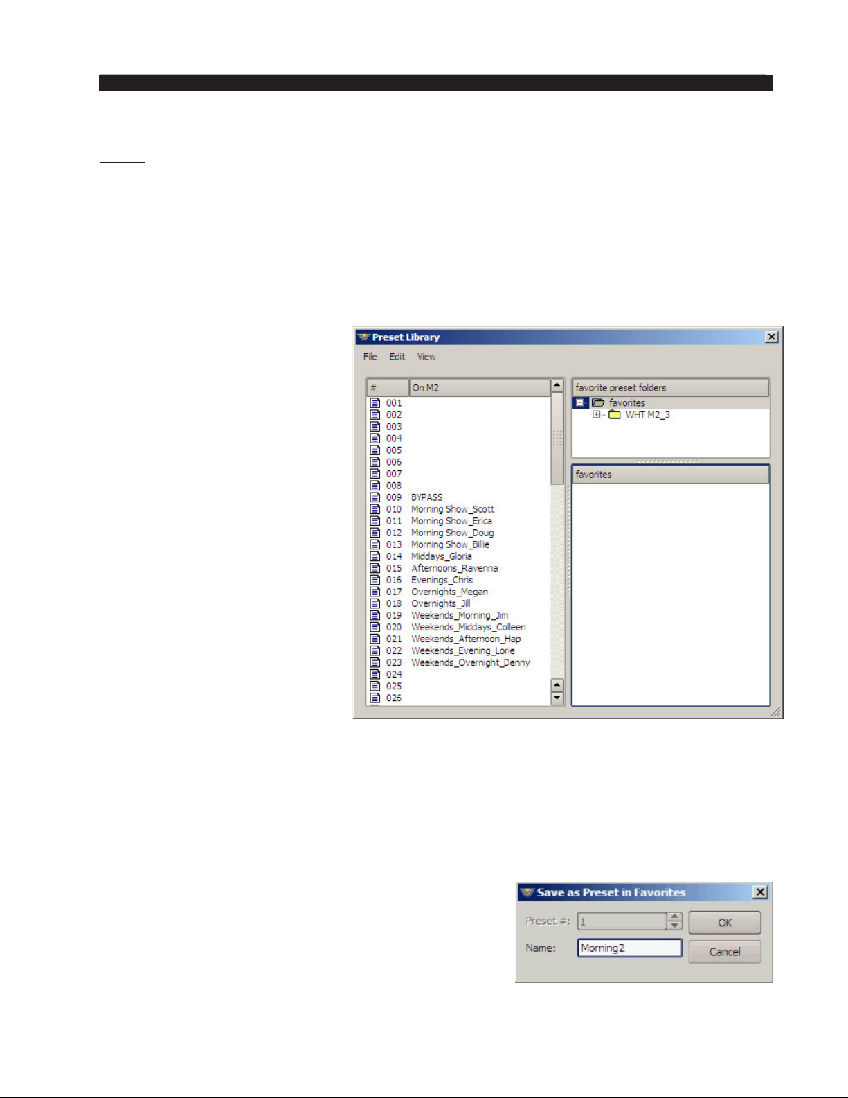
M-2 OPERATING GUIDE
IMPORTANT! Always remember to save your present settings as a preset name
before invoking other presets from the list or your settings will be lost… forever!
There is another level of preset management that we will discuss in more detail later,
and that is the preset package. A preset package is simply a collection of presets (or even
one preset!). When the GUI is used to create, or build, a package, what happens is that
the data from a number of individual preset les are combined into a single compressed
le having an extension of .pkg. This allows you to transfer a group of presets from one
M-2 to another as a single le, rather than as a set of les.
Library Button
The brunt of the preset man‑
agement tasks are performed from
the Preset Library form that comes
up when you press the “Library”
button in the Side Bar. The form
shows preset folders in the upper
pane and individual preset les in
the lower pane.
A menu has various items
depending on what you have
highlighted in the upper or lower
pane. From this dialog box you
can take, save, rename, move, or
delete presets, and you can also
export and import preset pack‑
ages. When you are done with this
form, click the “X” in the upper
right corner to close it. You will
need to close this form before you
can adjust any GUI controls.
It is important to remember
that the dialog window is split
logically down the middle ‑ the
left side shows what is on the actual M‑2 hardware while the right side shows what is
available on the local PC hosting the GUI.
The following menus and sub‑menus appear when the dialog box is used as described.
File Menu
The File menu contents depend on whether you have a folder or preset highlighted.
The following choices are possible if a folder is highlighted:
Save - This selection brings up the “Save as Preset
in Favorites” dialog box, allowing you to save a new
preset within the folder you have highlighted. Enter the
name for the new preset, then click the OK button. Click
Cancel if you change your mind before you’re done.
M-2 / Oct 2009
page 2 – 31
Page 54
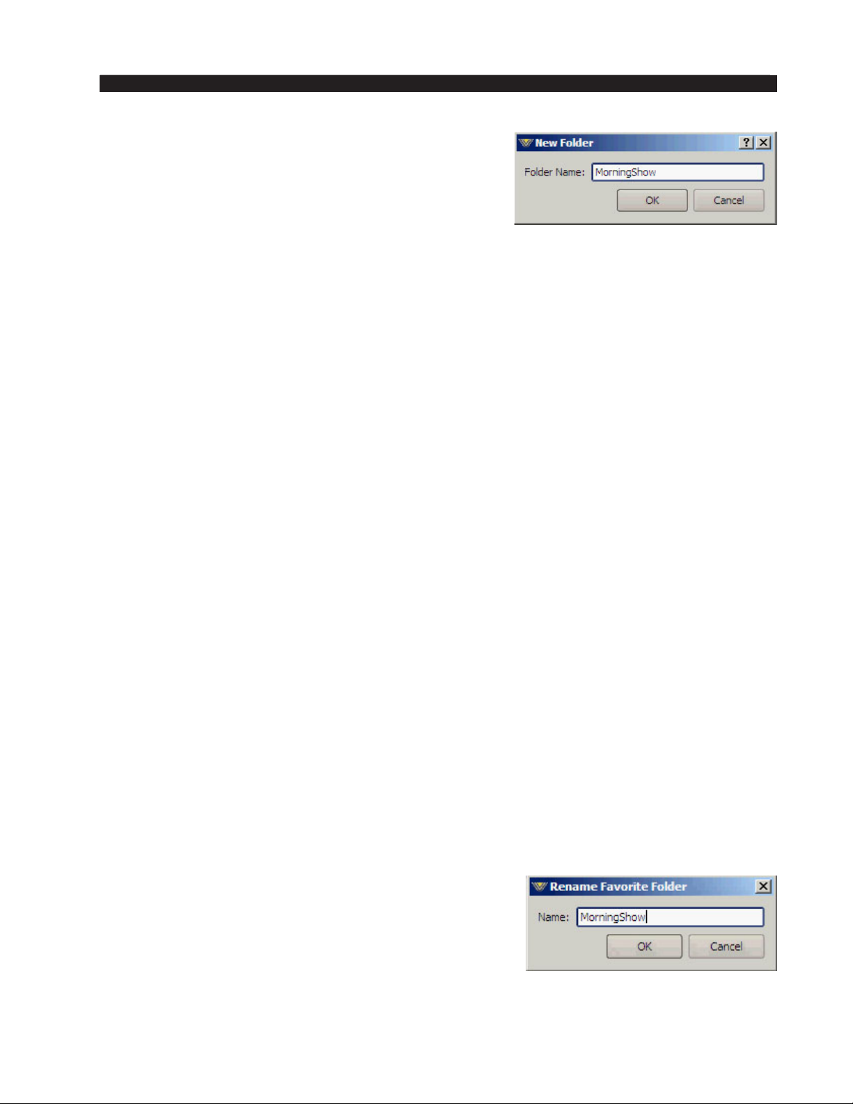
M-2 OPERATING GUIDE
New Folder... - This selection brings up the “New
Folder” dialog box, allowing you to create a new subfolder within the folder you have highlighted. Enter the
name for the new folder and then click the OK button.
Click Cancel if you change your mind before you’re
done.
Install Preset Package... - This selection brings up the “Install Preset Package”
dialog, which is a standard Windows Open dialog box. The dialog looks for les of
type “Preset Packages (*.pkg)” and starts its search within the M-2 install directory.
A package thus imported appears in the Presets dialog box as a new package folder under
favorites, having the same name as the .pkg le but without the extension.
The package folder appears as a folder but has a light red coloring within the icon
to distinguish it from a standard folder icon. It is possible, but not necessarily recom‑
mended, to install the same package twice (or a second package with the same name
as the rst). The second import will have the same name as the rst with the addition
of the text “(2).”
Build Preset Package... - This selection brings up the “Build Preset Package” dia‑
log, a standard Windows Save dialog box, allowing you to save all of the presets in the
highlighted folder, as well as any sub-folders and their enclosed presets, as a le of type
“Preset Packages (*.pkg).” The default le name, which you can change, is the name
of the highlighted folder with the extension .pkg added to it, and the default location to
save the le to, which you can also change, is the M-2’s install directory.
The following choices are possible if a preset is highlighted:
Save - Brings up the previously discussed “Save as Preset in Favorites” dialog box.
Take - This selection takes the preset, just like double-clicking a le name in the
“Take Preset” window.
Edit Menu
The Edit menu contents also depend on whether you have a folder or preset high‑
lighted. The following choices are possible if a folder is highlighted:
Paste ‑ This selection pastes the clipboard contents (one or more presets) into the
highlighted folder.
Remember! There is no overwrite warning! If the target folder already contains a
preset of the same name as one being copied, the one from the clipboard will overwrite
the one currently in the target folder.
Delete - This selection deletes the highlighted folder after rst asking if you are
sure this is what you want to do. This menu item is grayed out if you have the top level
Favorites folder highlighted; you can’t delete this folder.
Rename... - This selection brings up the “Rename
Favorite Folder” dialog box, allowing you to rename
the folder. Enter the new name for the folder, then click
the OK button. Click Cancel if you change your mind
before you’re done. This menu item is grayed out if the
highlighted folder is really a preset package. It is also
grayed out if you have the top level Favorites folder
highlighted; you can’t rename this folder.
M-2 / Oct 2009
page 2 – 32
Page 55
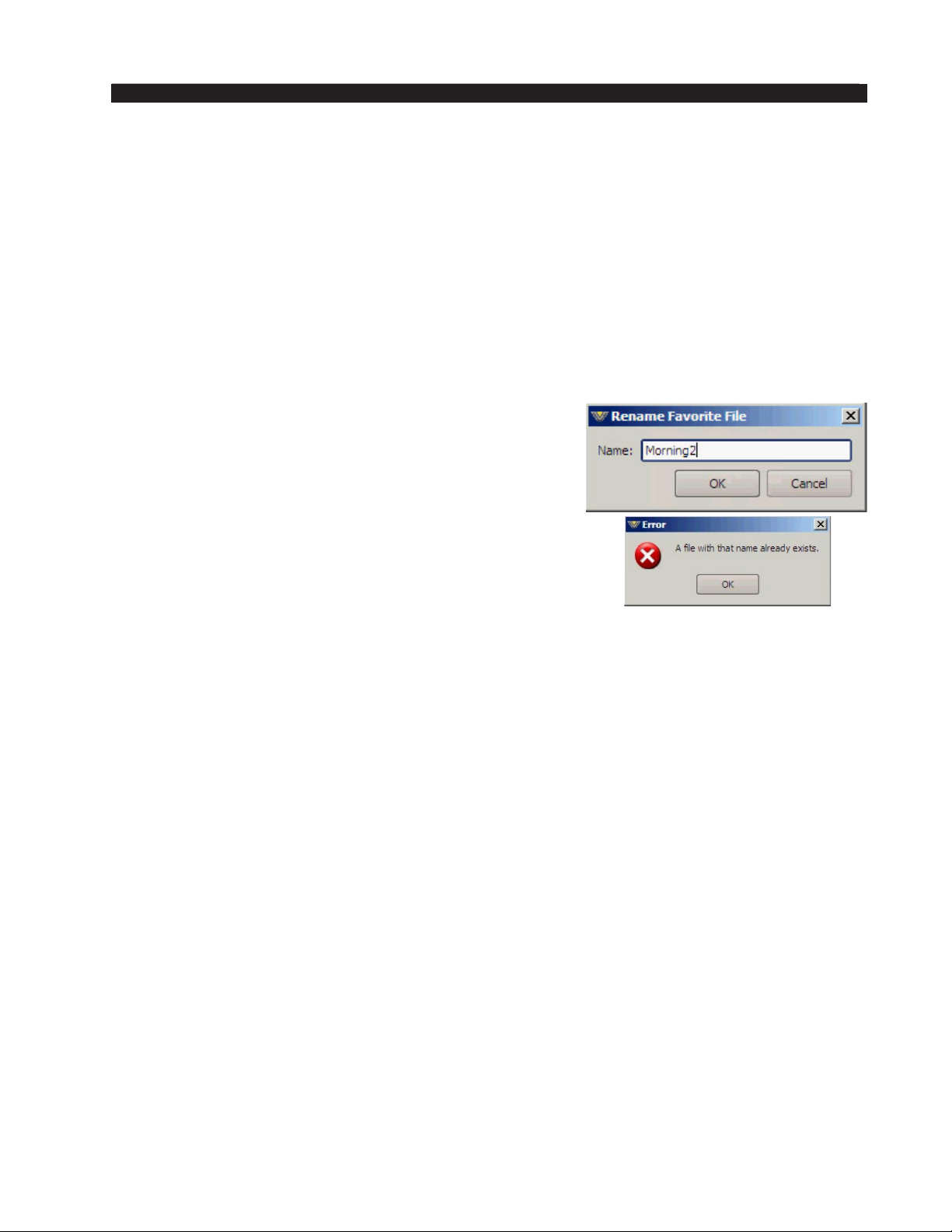
M-2 OPERATING GUIDE
The following choices are possible if a preset is highlighted (please note that use
of the Shift or Ctrl keys allows you to select multiple preset les for the following
operations):
Copy ‑ This selection copies the highlighted preset(s) to the clipboard.
Paste ‑ This selection pastes the preset(s) in the clipboard to the same folder as the
highlighted preset le is in.
Remember! There is no overwrite warning! If the target folder already contains
a preset of the same name as one being copied, the one from the clipboard will
overwrite the one currently in the target folder.
Delete - This selection deletes the highlighted preset(s) after rst asking if you are
sure this is what you want to do. There is no Undo function for preset deletes.
Rename... - This selection brings up the “Rename
Favorite File” dialog box, allowing you to rename the
preset le. Enter the new name for the folder, then click the
OK button. Click Cancel if you change your mind before
you’re done. If you have multiple preset les selected,
the “Rename Favorite File” dialog box appears multiple
times in sequence, allowing you to rename each le you
have selected. If you try to rename a le to the same name as
an already existing le you get an error message as shown.
Sort Up ‑ Moves the highlighted preset(s) up in the list.
Sort Down ‑ Moves the highlighted preset(s) down in
the list.
View Menu
The View menu is only available when you have a preset le highlighted. The fol‑
lowing choices are possible:
Settings... - This selection brings up the “Preset View” form (shown on the next
page), which displays a list of all the settings and their values for that particular preset
in two re-sizable columns:
Setting presents the name of the control, such as “Input Mic Gain,” while Value
indicates the value that control is set to in the preset, such as “-4.0 dB.” Click the “X”
in the upper right corner of the form to close it.
If you have multiple preset les selected the “Preset View” form appears multiple
times in succession, allowing you to view the settings of each preset in turn. Upon
clicking the “X” to close the form for one preset the form reappears for the next preset,
and so on until all presets have been viewed.
Diff... - This selection brings up the “Preset Difference” form (shown on the next
page), which displays three re-sizable columns:
M-2 / Oct 2009
page 2 – 33
Page 56
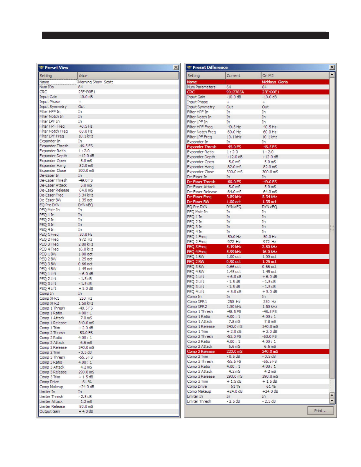
M-2 OPERATING GUIDE
M-2 / Oct 2009
page 2 – 34
Page 57
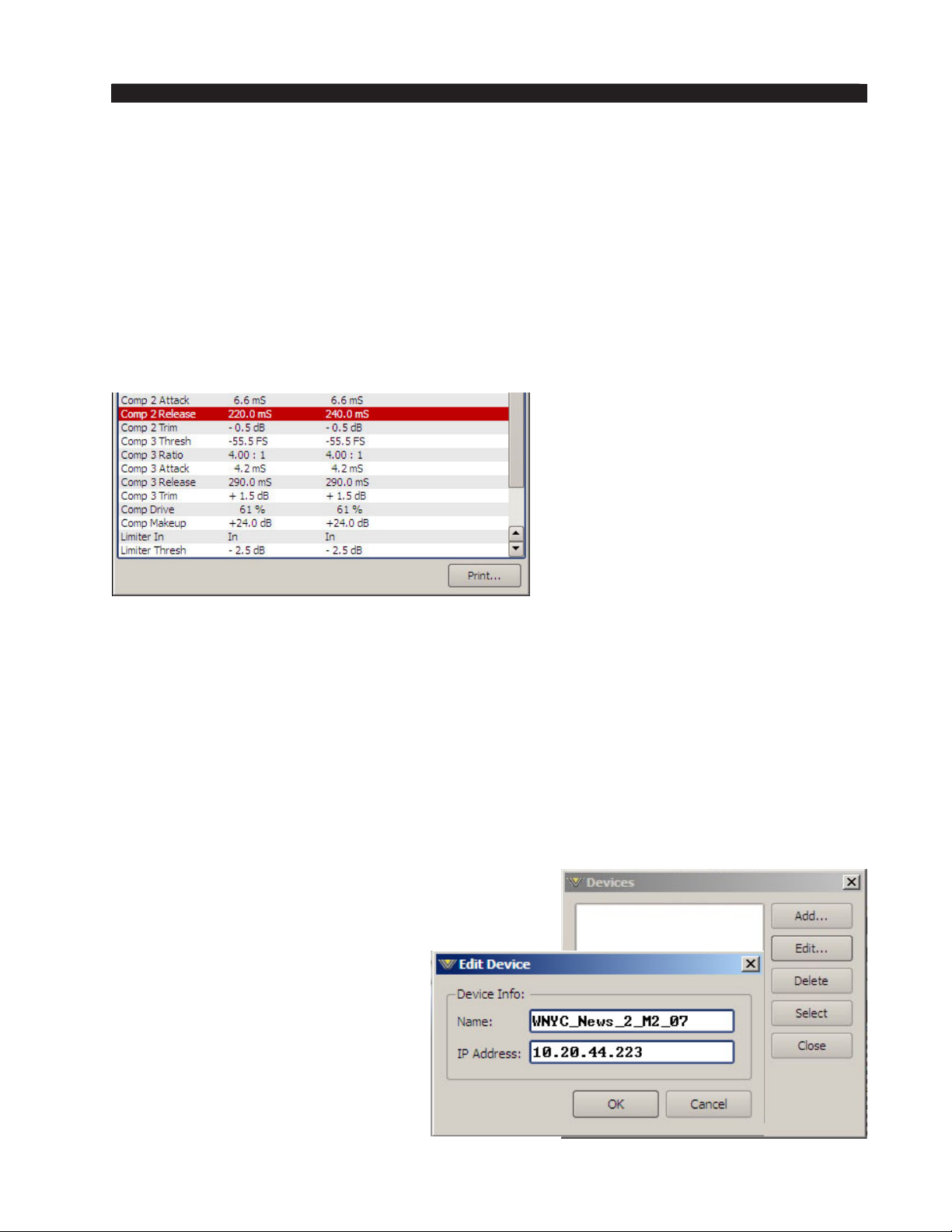
M-2 OPERATING GUIDE
Setting… ‑ The names of all the controls available in the M‑2’s dual processing
chains.
Ch (for Channel)… ‑ Indicates which processing channel a particular control has
a value set for.
Current… ‑ Displays the current setting of the named control.
Favorite… ‑ Presents the value that the control was set in the M‑2 hardware before
the control was changed to the new setting reected in Current (above).
A “Print” button at the bottom of the form allows you to produce a printout of the
differences as displayed.
On a color printer any line
that has a difference between
what is stored in the preset that
was last loaded and the current
control settings will show up in
red.
There is an “X” in the upper
right corner of the form which can be used to close the dialog. If you have multiple
preset les selected the “Preset Difference” form appears multiple times in succession,
allowing you to view the difference information for each preset in turn. Upon clicking
the “X” to close the form for one preset, the form reappears for the next preset, and
so on until differences have been viewed for all presets.
Print.. ‑ This selection brings up a standard Windows Print dialog box, allowing
you to print the settings for the selected preset to any Windows-dened printer.
Devices Button
The devices button allows access to the communica‑
tion conguration settings for the M-2. By clicking the
“Add…” button, new M-2 devices can be congured
for communication with the GUI. The
following “Edit Device” dialog will
appear:
Under “Device Info” you can enter
the pet name of the M‑2 processor that
you are conguring. Then, in the IP Ad‑
dress box, enter the IP address that the
M‑2 should be using on your particular
network. After this is done you may
click “OK” on the Edit Device box.
M-2 / Oct 2009
page 2 – 35
Page 58
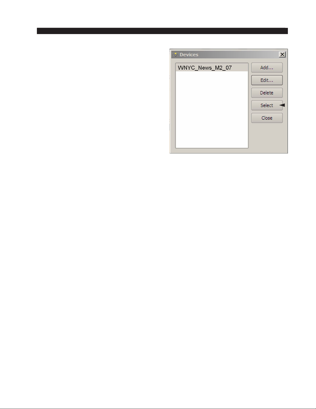
M-2 OPERATING GUIDE
Then, in the Devices Dialog box highlight
(single left click) the M‑2 device that you just
added (shown highlighted in the image on the
left) and click on “Select.”
This step tells the GUI specically which
M‑2 you want to connect to.
M-2 / Oct 2009
page 2 – 36
Page 59
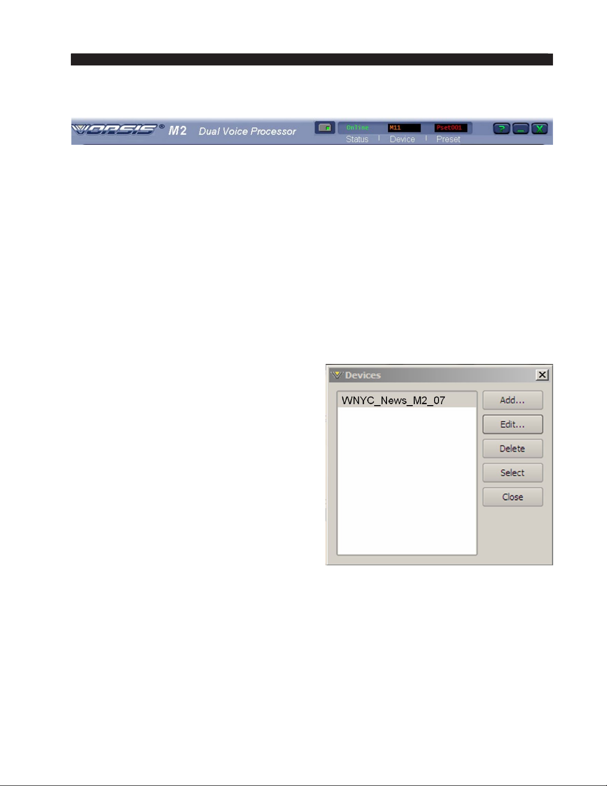
M-2 OPERATING GUIDE
Title Bar Region
Along the top edge of the M-2 GUI screen (in line with the “M2 Dual Voice
Processor” product label to the left, and the Windows About, Minimize, and Exit
icons to the right) are “Status” and “Devices” indicators. The M-2 GUI is capable
of controlling multiple M-2 units (“Devices”). Whether a connection is made (“Sta‑
tus”) or not, the device presently under command is indicated in the “Devices” box.
Double-clicking the “Devices” button on the left will gain access to device manage‑
ment screens.
Status
This indicates: “Online,” meaning the GUI is in communication with and directly
reects an M-2; “Ofine,” meaning the GUI and M-2 are disconnected and not
communicating; or “Trying,” meaning the GUI is attempting to nd the M-2 on the
LAN and connect to it. An adjacent button toggles between “Online” and “Ofine.”
Devices
The name assigned to the M‑2 to which the
GUI is either currently congured to connect to
or is currently connected to (or with which it is
attempting to connect) shows in this window.
Double‑clicking on the name area brings up
the “Devices” dialog box. A list of M-2 devices
that have been congured by the GUI are shown
here. Highlighting the desired M‑2’s name and
then hitting the “Select” button tells the GUI
which M‑2 it is to connect.
In the event no M‑2’s are listed or one is
adding an additional device, “Add” brings up a
small dialog box which asks for the new M‑2’s
unit name and assigned IP address.
Network Notes
• The M-2 utilizes static TCP/IP addressing and does not use DHCP (Dynamic
Host Conguration Protocol); therefore it must be assigned its own IP address.
Please consult your local network administrator if the M-2 network congura‑
tion poses any unusual challenges.
• The M-2 utilizes both TCP and UDP protocols while communicating with the
remote GUI. Therefore the interconnecting network and its hardware (routers,
switches, etc.) must be able to pass Ethernet packet trafc to/from the M-2 on
TCP port 55898 and UDP ports 60000 through 60010.
M-2 / Oct 2009
page 2 – 37
Page 60
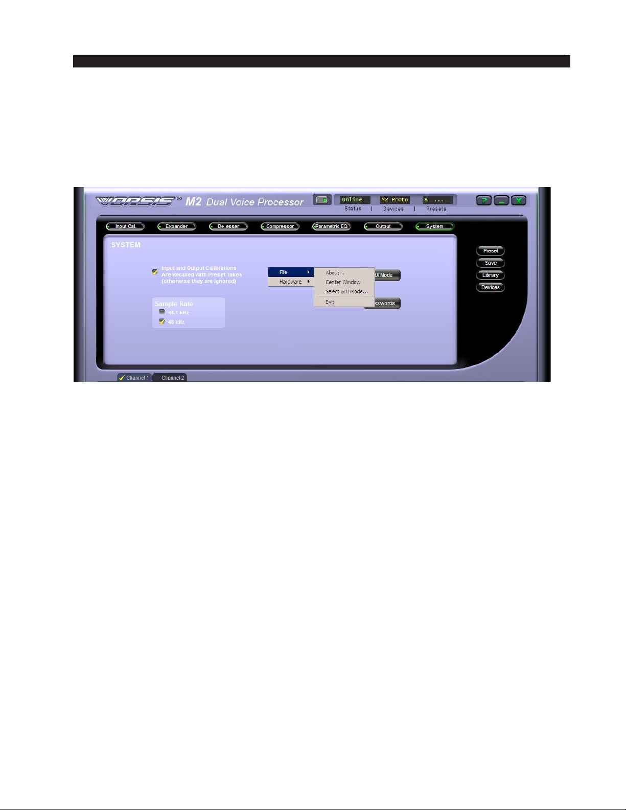
M-2 OPERATING GUIDE
Accessing Menu Options
Right clicking anywhere on the controls area of the main M‑2 GUI will open a pop up
menu tree with access to File, Hardware, and Presets choices. These choices lead to sub‑
menus and dialog boxes that may also be accessed by clicking on other dedicated buttons
on the main M‑2 control panel. As with many Windows programs, there are multiple ways
to access menu trees ‑ go ahead and explore!
File Menu Items
The File menu tree may be accessed by right clicking anywhere on the controls area of
the main M-2 GUI. Sub-menu choices include:
About... ‑ brings up the GUI program’s About splash screen. Click anywhere on the
splash screen to dismiss this screen.
Center Window ‑ centers the GUI window on your display.
Select GUI Mode... - brings up the “Select GUI Mode” form discussed earlier.
Exit ‑ closes the GUI program. Any connected device will continue to operate.
Hardware Menu Items
The Hardware menu tree may be accessed by right clicking anywhere on the controls
area of the main M‑2 GUI. Please note that many of these functions require you to be con‑
nected (Online) to an M-2. Sub-menu choices include:
Devices... - opens the “Devices” dialog box. Allows the creation, editing, selection, and
deleting of M‑2 processors connected to your system.
On-Line Mode... - toggles between ONLINE and OFFLINE modes.
Login Password... ‑ opens the Passwords dialog box for editing login passwords.
Version... ‑ displays the current software versions running on your M‑2.
Update - opens the “Choose a le to download” dialog box. Only les of type *.vbn are
visible. See the later section on software updates.
Assign IP Address... ‑ opens a dialog box that allows the user to change the IP address
parameters of the M‑2. Please see the Read Me! at the beginning of this manual for com‑
plete details on changing the M-2’s network conguration settings to match those of your
local area network.
M-2 / Oct 2009
page 2 – 38
Page 61

M-2 OPERATING GUIDE
Software Updates
At Wheatstone we are always improving our products and future versions of the M‑2’s
internal software may be released to implement new features or correct known problems.
The Software Update menu choice opens a dialog box and prompts the user to select
a le to be uploaded to the M-2. Upon completion, you will be asked to restart the M-2
(cycle power). Note that due to the M-2 specic content of the update le and its heavy
encryption only veried updates provided by our factory will be accepted by the M-2
during an update process!
M-2 / Oct 2009
page 2 – 39
Page 62

APPENDIX
Appendix
Contents
Parameters, Units and Ranges .....................................................A-2
M-2 / Oct 2009
page A – 1
Page 63

APPENDIX
Parameters, Units and Ranges.
Approximately following the M-2’s signal path, these are the values and ranges
appropriate to each processing channel.
System Level
Headroom: 20dB
Nominal Operating Level: -20dBFS
LED Input/Output Level Meter
Input
Type: Very Low Noise Electronic Differential
Input Impedance: > 2kohms at 1kHz
Optimum Source Impedance: 200 ohms
Phantom Power
Maximum Gain: 70dB
Minimum Gain: -10dB
Gain Adjust Increments: 1dB
Equivalent Input Noise: º-128dBu
Frequency Response: + / - 0.2dB
THD+N: <0.03%20Hz - 20kHz@-50dBu input
SMPTE DIM: 0.00007%
Filters
a. High-Pass Filter
Filter Class: 24dB/oct. Butterworth
Frequency: 20Hz – 1kHz
Defaults: Off
b. Low-Pass Filter
Filter Class: 24dB/oct. Butterworth
Frequency: 1kHz – 20kHz
Defaults: Off
c. Notch Filter
Filter Class: 24dB/oct. Butterworth
Frequency: 20Hz – 20kHz
Defaults: Off
M-2 / Oct 2009
page A – 2
Page 64

APPENDIX
Equalization
Four identical, independent bands of parametric equalization:
Frequency: 20Hz – 20kHz
Bandwidth: 0.2 – 3 octaves
Lift / Cut: + / - 14dB
Defaults: All off
Phase Scrambler
Filter Class: 4th order all pass
Phase Delay: 0 to 720 degrees, frequency dependent
De-Esser
Type: Recursive-style true (not broadband) De-Esser
Threshold: -10 to -60dBfs
Release: 50mS – 500mS
De-Ess Frequency: 20Hz – 20kHz
Defaults: Off
Expander
Type: Downward Expander
Threshold: -60 – 0dBfs
Close: 50mS – 3Sec.
Depth: 0 – 40dB
Defaults: Off
Compressor
Threshold: -70 to -30dBfs
Attack: 0.2mS – 1S
Release: 33mS - 1Sec.
Ratio (soft-knee): 1:1 – 1:20
Control
All parameters accessible via an intuitive MS Windows® compatible graphical user
interface via Ethernet interface. Three levels of user access are available: Expert, Simpli-
ed, and Talent.
M-2 / Oct 2009
page A – 3
Page 65

APPENDIX
Please contact Wheatstone technical support for assistance or futher information
regarding the M-2 product.
Wheatstone Corporation
600 Industrial Drive
New Bern, North Carolina, USA 28562
252-638-7000, fax 252-637-1285
M-2 / Oct 2009
page A – 4
 Loading...