

Page 1

FM - 531HD
FM & HD Digital auDio Processor
Technical
Manual
600 Industrial Drive, New Bern, North Carolina 28562 (tel 252-638-7000 / fax 252-637-1285 )
Page 2

FM - 531HD
FM & HD Digital auDio Processor
Technical
Manual
Wheatstone Corporation
May 2013
Page 3

ORSIS
Ultra-HigH resolUtion Processing
FM-531HD FM & HD Digital Augio Processor Technical Manual - Software Version 2.0.0 and higher
©2013 Wheatstone Corporation
FM-531HD / May 2013
600 Industrial Drive
New Bern, North Carolina 28562
tel 252-638-7000 / fax 252-637-1285
Page 4
Attention!Attention!
Federal Communications Commission (FCC) Compliance
Notice:
Radio Frequency Notice
NOTE: This equipment has been tested and found to comply with the
limits for a Class A digital device, pursuant to Part 15 of the FCC rules. These
limits are designed to provide reasonable protection against harmful interference when the equipment is operated in a commercial environment. This
equipment generates, uses, and can radiate radio frequency energy and, if
not installed and used in accordance with the instruction manual, may cause
harmful interference to radio communications. Operation of this equipment
in a residential area is likely to cause harmful interference in which case the
user will be required to correct the interference at his own expense.
This is a Class A product. In a domestic environment,
this product may cause radio interference, in which case,
the user may be required to take appropriate measures.
This equipment must be installed and wired properly in order to assure
compliance with FCC regulations.
Caution!
Wheatstone could void the user's authority to operate this equipment.
Any modications not expressly approved in writing by
FM-531HD / May 2013
Read Me!
Page 5
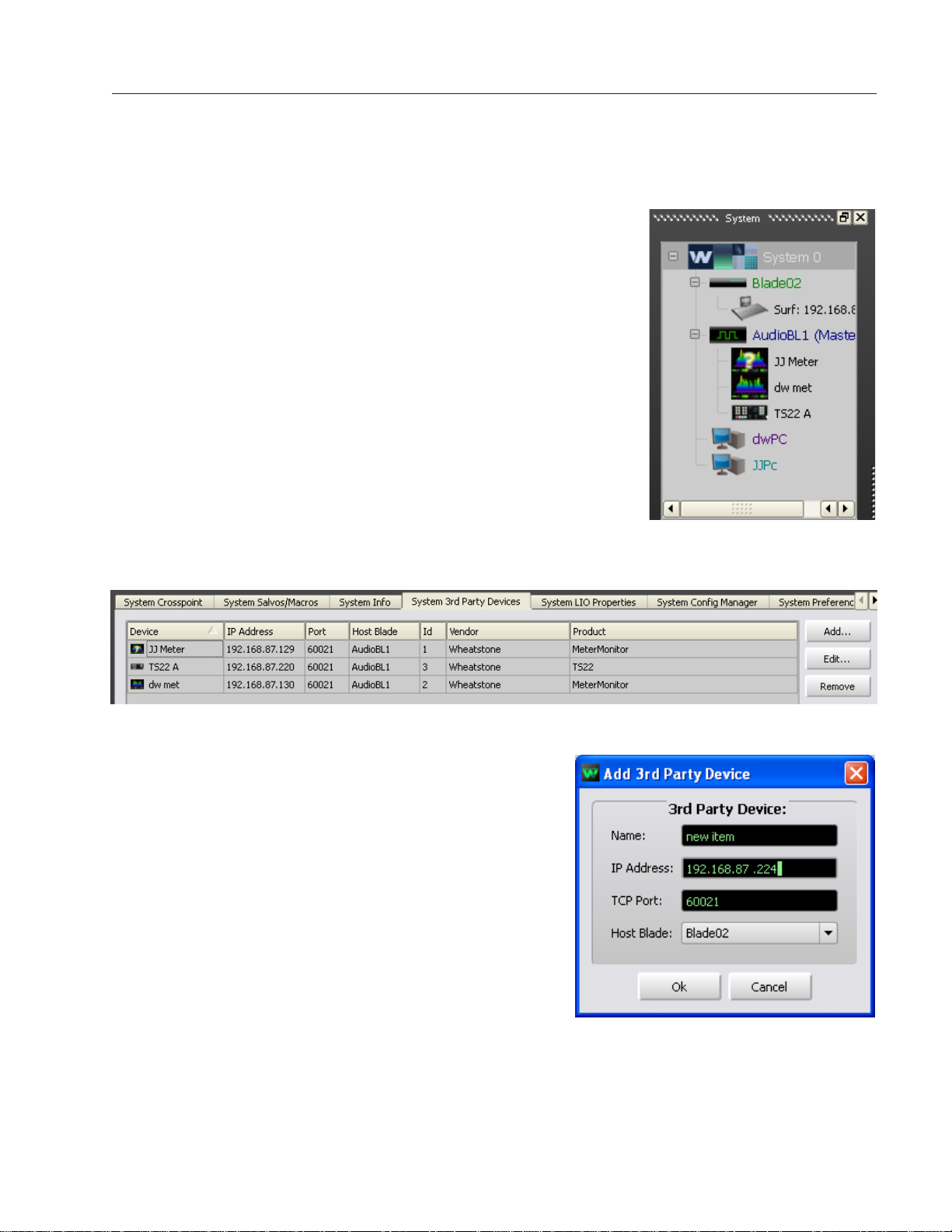
Adding Devices To The 3rd Party Tab
In order to utilize all the features of the FM‑531HD Digital
Audio Processor the device must be added to the System 3rd Party
Devices tab in the Wheatstone WheatNet‑IP Navigator program
(aka the Navigator GUI). This sheet shows you the basics of that
procedure. Refer to the WheatNet‑IP Audio Over IP Network
Technical Manual for additional details.
You will need to know the IP address of the device being
added, so you will want to nd that out before you start.
Launch the Navigator GUI and make sure that System 0 is
selected in the System pane. You will see something like this:
Now, to the right of the System pane, select the System 3rd Party Devices tab.
Click the Add button to bring up the Add 3rd Party Device dialog:
Type in a convenient Name and insert the IP Address
of the device being added. Leave the TCP Port at the
default setting of 60021. From the Host Blade drop down
select the Blade that you want to associate the 3rd Party
device with. Click Ok.
This completes the process of adding the device to the
System 3rd Party Devices tab. The added device should
show up in the System pane under the Blade you added
it to. If it does not show up, or if it shows up but has a
yellow question mark on it, then there is either a network
issue that needs attention, or the device is not connected
to the network at all, or one or more steps have been
omitted or done incorrectly in the conguration process.
FM-531HD / Feb 2014
Read Me!
Page 6

CONTENTS
FM-531HD Technical Manual
Table of Contents
Chapter 1 - General Information
Introduction ....................................................................................1-2
FM-531HD Feature Overview ........................................................ 1-3
Rack Mounting ............................................................................... 1-3
FM-531HD Installation Tips ........................................................................................1-4
Grounding ...............................................................................................................1-4
Surge Protection .....................................................................................................1-4
UPS/Power Conditioning .......................................................................................1-5
Analog Audio Input Connections............................................................................1-5
Analog Audio Output Connections .........................................................................1-5
Digital Audio/baseband192 Connections ...............................................................1-6
Where to Install the FM-531HD ..................................................................................1-7
Analog Left/Right STL ............................................................................................1-7
Composite Analog STL ..........................................................................................1-7
Analog Phone Lines ...............................................................................................1-7
Digital STL ..............................................................................................................1-8
Where Should Pre-Emphasis Go? ..........................................................................1-8
Arbitron People Meter (PPM) ..................................................................................1-9
AC Power Considerations ............................................................1-9
Front Panel Interface .................................................................... 1-10
FM-531HD Front Panel Navigation ...........................................................................1-10
Basic Setup ...............................................................................................................1-11
Rear Panel Connections ..............................................................1-13
Audio Inputs ..............................................................................................................1-14
Analog In ................................................................................................................1-14
AES In .....................................................................................................................1-14
SCA In ....................................................................................................................1-14
FM Audio Outputs .....................................................................................................1-14
Analog Out .............................................................................................................1-15
AES/baseband192 Out ...........................................................................................1-15
TX Out ....................................................................................................................1-15
HD Audio Outputs (optional) .....................................................................................1-15
HD AES Out ............................................................................................................1-15
Headphone Monitoring ..............................................................................................1-15
Network Connection .................................................................................................1-16
Ethernet RJ-45 .......................................................................................................1-16
Typical Ethernet Cable ...........................................................................................1-16
Typical Crossover Cable ......................................................................................... 1-16
General Purpose Interface (GPI) ................................................................................1-17
GPI ..........................................................................................................................1-17
Processing Presets .................................................................................................1-17
Analog XLR Connections Pinouts Drawing ...............................................................1-19
Digital XLR Connections Pinouts Drawing ................................................................1-19
BNC Connections Pinouts Drawing ..........................................................................1-21
Ethernet RJ-45/GPI DB-9 Pinouts Drawing .............................................................1-22
FM-531HD / May 2013
page Contents – 1
Page 7

CONTENTS
Chapter 2 - PC Based Audio Processing Guru
®
GUI
Installation ......................................................................................2-3
Changing FM-531HD’s IP Address Configuration ...................... 2-5
Reconfiguring The Remote GUI ...................................................2-6
Connecting Directly Without a LAN ............................................. 2-6
About DHCP and FM-531HD ......................................................... 2-6
FM-531HD’s Ethernet Ports and Network Protocols .................. 2-6
If the GUI “Connected” But the Meters and Analysis Displays
Don’t Work ..................................................................................................................2-7
Using Guru GUI ..............................................................................2-8
Input Menu .................................................................................................................2-9
Input Source ............................................................................................................2-9
Audio Input Signal Presence Indicators ..................................................................2-9
Automatic Input Failover .........................................................................................2-9
Analog Gain ............................................................................................................2-10
Digital Gain .............................................................................................................2-10
L/R Balance ............................................................................................................2-10
Output Menu .............................................................................................................2-10
Stereo Encoder Menu ...............................................................................................2-11
MPX Processor Style ..............................................................................................2-11
MPX Process Control .............................................................................................2-12
BS412 MPX Power Controller ................................................................................2-12
Pilot Injection ..........................................................................................................2-13
Emphasis ................................................................................................................2-13
SCA-1 and SCA-2 Inputs .......................................................................................2-13
TX-1 and TX-2 Outputs ..........................................................................................2-13
Presets Menu ............................................................................................................2-14
Selecting a Preset ..................................................................................................2-14
Saving a Preset ......................................................................................................2-14
Preset Library Functions ........................................................................................2-14
Locking Presets ..................................................................................................2-15
How to View Preset Changes .............................................................................2-15
Quick Save .............................................................................................................2-16
System Menu ............................................................................................................2-17
Input/Output Settings Change With Presets ..........................................................2-17
Metering Data via TCP/IP .......................................................................................2-17
Headphone Source ................................................................................................2-18
Headphone Volume Control ...................................................................................2-18
Status Indicators ....................................................................................................2-18
Temp ................................................................................................................... 2-18
Analog ................................................................................................................2-18
Digital .................................................................................................................2-18
Remote Login .........................................................................................................2-19
Events .....................................................................................................................2-19
Creating a Weekly Rotation Schedule ................................................................2-19
Creating a Long Term Rotation Schedule .......................................................... 2-20
Deleting a Scheduled Event ...............................................................................2-20
FM-531HD / May 2013
page Contents – 2
Page 8

CONTENTS
Setting System Time ..............................................................................................2-21
SNTP (Simple Network Time Protocol) ..............................................................2-21
Sound Menu.. ............................................................................................................2-22
FM Sound Adjust ....................................................................................................2-22
AGC Depth .........................................................................................................2-22
Compression ......................................................................................................2-22
Density ................................................................................................................2-23
Low/Warm EQ ....................................................................................................2-23
Mid/High EQ .......................................................................................................2-23
Loudness ............................................................................................................2-23
HD Sound Adjust ....................................................................................................2-24
Density ................................................................................................................2-24
Low/Warm EQ ....................................................................................................2-24
Mid/High EQ .......................................................................................................2-24
Loudness ............................................................................................................2-24
Audio Input and Output Metering.. ............................................................................2-25
Audio Processing Gain Reduction Displays.. ............................................................2-26
Analysis Menu... ........................................................................................................2-27
FFT .........................................................................................................................2-27
O-Scope .................................................................................................................2-28
E vs. F .....................................................................................................................2-28
3-D Plot ..................................................................................................................2-29
SDR™ .....................................................................................................................2-29
A-Clip .....................................................................................................................2-29
Accessing Menu Options.. ........................................................................................2-30
Chapter 3 - FM-531HD Pro GUI
Getting Started ...............................................................................3-5
Configuring The Pro GUI ..............................................................3-5
Connecting Directly Without a LAN ............................................................................3-6
PC System Requirements ..........................................................................................3-6
The Really Remote Connection! ................................................................................3-6
VPN ............................................................................................................................3-6
The FM-531HD and Internet Security Concerns ........................................................ 3-7
About DHCP and The FM-531HD ..............................................................................3-7
The FM-531HD Ports and Network Protocols ...........................................................3-7
Using The Pro GUI ......................................................................... 3-8
Dynamic Displays Region ...........................................................................................3-9
Frequency-Domain Graph .......................................................................................3-9
The FM-531HD Graphical Interface Operation .......................................................3-9
Metering and Analysis ............................................................................................3-12
Control Area Region ..................................................................................................3-14
Input Setup Menu ...................................................................................................3-15
Input Source .......................................................................................................3-15
Input Signal Presence ........................................................................................3-15
Input Failover ......................................................................................................3-15
Analog Input Gain ...............................................................................................3-16
Digital Input Gain ................................................................................................3-16
L/R Balance ........................................................................................................3-16
Phase Rotator .....................................................................................................3-16
HPF - High Pass Filter ........................................................................................3-17
FM-531HD / May 2013
page Contents – 3
Page 9

CONTENTS
Equalizer Menu .......................................................................................................3-18
EQ Enable ...........................................................................................................3-19
AGC + SST Menu ...................................................................................................3-20
What is SST? ......................................................................................................3-20
SST Controls Overview ......................................................................................3-21
SST Drive .....................................................................................................3-21
SST Gate Threshold ....................................................................................3-21
Ramp Rate ..................................................................................................3-21
Window Size ................................................................................................3-22
SST Linear/Adaptive Options ......................................................................3-22
A Word (or two) About Outboard Processors .....................................................3-23
Multiband AGC Controls ....................................................................................3-25
AGC Drive ....................................................................................................3-25
Gated Mode ................................................................................................3-25
AGC Gate Threshold ...................................................................................3-25
Band Coupling .............................................................................................3-26
AGC Backoff ................................................................................................3-26
AGC/Compressor Sidebar Menu .......................................................................3-27
AGC Attack ..................................................................................................3-27
AGC Release ...............................................................................................3-27
Compressor Attack .....................................................................................3-27
Compressor Release ...................................................................................3-27
AGC Mixer ...................................................................................................3-27
Stereo Enhance ...........................................................................................3-27
HD Limiter Menu ....................................................................................................3-28
31 Band Drive .....................................................................................................3-28
31 Band Limiter Sidebar .....................................................................................3-28
Threshold .....................................................................................................3-29
Attack ..........................................................................................................3-29
Release ........................................................................................................3-29
Lookahead Limiter ..............................................................................................3-29
Limiter Enable ..............................................................................................3-30
L/R Linked ...................................................................................................3-30
Final Limiter Drive ........................................................................................3-30
Limiter Threshold .........................................................................................3-30
Attack Time .................................................................................................3-30
Release Time ...............................................................................................3-31
Delayed Release ..........................................................................................3-31
VBMS .................................................................................................................3-31
Drive ............................................................................................................3-31
Style .............................................................................................................3-31
Output .........................................................................................................3-32
VBMS Frequency ........................................................................................3-32
VBMS Metering ...........................................................................................3-32
Digital Output .....................................................................................................3-32
L/R Reverse .................................................................................................3-33
Phase Reverse ............................................................................................3-33
FM Limiter Menu ....................................................................................................3-33
31 Band Drive .....................................................................................................3-33
31 Band FM Limiter Sidebar ..............................................................................3-34
Threshold .....................................................................................................3-34
Attack ..........................................................................................................3-34
Release ........................................................................................................3-34
FM-531HD / May 2013
page Contents – 4
Page 10

CONTENTS
Main Clip Drive ...................................................................................................3-34
Pre-Emphasis .....................................................................................................3-34
VBMS .................................................................................................................3-35
Drive ............................................................................................................3-35
Style .............................................................................................................3-35
Output .........................................................................................................3-35
VBMS Frequency ........................................................................................3-35
VBMS Metering ...........................................................................................3-36
Digital Output .....................................................................................................3-36
AES3 Digital .................................................................................................3-36
FM Diversity Delay ..............................................................................................3-36
Entering Delay Values Manually ..................................................................3-37
Stereo Encoder Menu ............................................................................................3-37
MPX Processor Style ..........................................................................................3-37
Composite Clipper ......................................................................................3-37
Look Ahead Limiter .....................................................................................3-38
MPX Process Drive .............................................................................................3-38
Multipath Controller ............................................................................................3-38
BS412 MPX Power Controller ............................................................................3-39
Pilot Injection ......................................................................................................3-40
Pilot Phase .........................................................................................................3-40
Stereo/Mono ......................................................................................................3-40
SCA 1 & 2 Gain ..................................................................................................3-40
TX 1 Level ..........................................................................................................3-40
TX 2 Level ..........................................................................................................3-40
Analog Output Type ........................................................................................... 3-41
Composite MPX ..........................................................................................3-41
Left/Right .....................................................................................................3-41
Left/Right De-Emphasized ..........................................................................3-41
Test Oscillator .................................................................................................... 3-41
System Menu .........................................................................................................3-42
Input/Output Settings Follow Preset Takes ........................................................ 3-42
Metering Data Over TCP/IP ................................................................................3-43
Remote Login .....................................................................................................3-43
Pro GUI Access ..................................................................................................3-44
Pro GUI Lock ......................................................................................................3-44
Status Indicators ................................................................................................3-45
Scheduler ...........................................................................................................3-46
Creating a Weekly Rotation Schedule .........................................................3-46
Creating a Long Term Rotation Schedule ................................................... 3-46
Deleting a Scheduled Event ........................................................................3-47
System Time .......................................................................................................3-47
Headphone Source ............................................................................................3-47
Headphone Control ............................................................................................3-48
Side Bar Region ........................................................................................................3-49
Presets ...................................................................................................................3-49
Save ........................................................................................................................3-49
Library ....................................................................................................................3-50
Locking Presets ..................................................................................................3-50
How to View Preset Changes .............................................................................3-51
Devices ...................................................................................................................3-51
Quick Save (QSave) ................................................................................................3-52
FM-531HD / May 2013
page Contents – 5
Page 11

CONTENTS
Title Bar Region .........................................................................................................3-53
Status .....................................................................................................................3-53
Device .....................................................................................................................3-53
Preset .....................................................................................................................3-54
Notes on Online and Ofine Working .....................................................................3-54
Accessing Menu Options ..........................................................................................3-55
View Menu Items ....................................................................................................3-55
Hardware Menu Items ............................................................................................3-55
FM-531HD Hardware Update ............................................................................3-56
Preset Menu Items .................................................................................................3-57
Appendices
Appendix A
General Specifications ..................................................................A-3
Appendix B
FM-531HD GPI Interface ................................................................A-9
Appendix C
Interpreting Common Audio Processing Terms ........................A-12
Background ...............................................................................................................A-12
Audio Terms and Wheatstone Processing ................................................................A-13
Thump/Rumble/Bottom ..........................................................................................A-13
Punch/Boom/Tubby/Warm .....................................................................................A-14
Mud ........................................................................................................................A-14
Honk .......................................................................................................................A-15
Whack ....................................................................................................................A-15
Fuzzy/Tinny ............................................................................................................A-15
Crunchy/Edgy .........................................................................................................A-15
Sibilance .................................................................................................................A-16
Treble/Bright/Open .................................................................................................A-16
Finally .....................................................................................................................A-17
Appendix D
Using The Factory Lock Utility ....................................................A-19
Background ...............................................................................................................A-19
Installation .................................................................................................................A-19
Using the Utility .........................................................................................................A-20
Conrming Factory Lock/Unlock Is Operational ....................................................A-21
Removing The Factory Lock/Unlock Options ...........................................................A-22
FM-531HD / May 2013
page Contents – 6
Page 12

GENERAL INFORMATION
General Information
Chapter Contents
Introduction ....................................................................................1-2
FM-531HD Feature Overview ........................................................ 1-3
Rack Mounting ............................................................................... 1-3
FM-531HD Installation Tips ........................................................................................1-4
Grounding ...............................................................................................................1-4
Surge Protection .....................................................................................................1-4
UPS/Power Conditioning .......................................................................................1-5
Analog Audio Input Connections............................................................................1-5
Analog Audio Output Connections .........................................................................1-5
Digital Audio/baseband192 Connections ...............................................................1-6
Where to Install the FM-531HD ..................................................................................1-7
Analog Left/Right STL ............................................................................................1-7
Composite Analog STL ..........................................................................................1-7
Analog Phone Lines ...............................................................................................1-7
Digital STL ..............................................................................................................1-8
Where Should Pre-Emphasis Go? ..........................................................................1-8
Arbitron People Meter (PPM) ..................................................................................1-9
AC Power Considerations ............................................................1-9
Front Panel Interface .................................................................... 1-10
FM-531HD Front Panel Navigation ...........................................................................1-10
Basic Setup ...............................................................................................................1-11
Rear Panel Connections ..............................................................1-13
Audio Inputs ..............................................................................................................1-14
Analog In ................................................................................................................1-14
AES In .....................................................................................................................1-14
SCA In ....................................................................................................................1-14
FM Audio Outputs .....................................................................................................1-14
Analog Out .............................................................................................................1-15
AES/baseband192 Out ...........................................................................................1-15
TX Out ....................................................................................................................1-15
HD Audio Outputs (optional) .....................................................................................1-15
HD AES Out ............................................................................................................1-15
Headphone Monitoring ..............................................................................................1-15
Network Connection .................................................................................................1-16
Ethernet RJ-45 .......................................................................................................1-16
Typical Ethernet Cable ...........................................................................................1-16
Typical Crossover Cable ......................................................................................... 1-16
General Purpose Interface (GPI) ................................................................................1-17
GPI ..........................................................................................................................1-17
Processing Presets .................................................................................................1-17
Analog XLR Connections Pinouts Drawing ...............................................................1-19
Digital XLR Connections Pinouts Drawing ................................................................1-19
BNC Connections Pinouts Drawing ..........................................................................1-21
Ethernet RJ-45/GPI DB-9 Pinouts Drawing .............................................................1-22
FM-531HD / May 2013
page 1 – 1
Page 13
GENERAL INFORMATION
General Information
Introduction
Welcome to the FM‑531HD Digital Audio Processor from Wheatstone. The FM‑531HD
has been carefully designed to deliver a clean and easy to listen to sound on the dial along
with very competitive loudness if that is the goal. The FM‑531HD expands on technologies
previously invented by Wheatstone, incorporates several technologies not available in other
processors, and delivers that “sought after” sound to traditional analog FM transmission.
Like other Wheatstone processors, the FM‑531HD has been carefully designed to not have
a xed sound of its own – the end user is free to use the vast pallet of tools to create any
desired on air sound.
The processing algorithms of the FM‑531HD have been carefully evaluated though
thousands of hours of critical listening and with a very wide range of program material. The
FM‑531HD can deliver a clean, clear, and if desired, loud on‑air sound. Music sounds like it
was meant to sound. Voices are rich and full and without unnatural coloration or distortion.
Transitions between widely varying program elements are deftly handled, and if desired,
with no trace of “processing” during spectral balance and density corrections.
Remote control of the FM‑531HD is via Windows‑based Graphical User Interface (GUI)
software and can be accomplished via 100BaseT wired Ethernet. Up to four simultaneous
remote control sessions are possible. Eight rear panel General Purpose Inputs (GPI) are
provided to allow hardware‑level interfacing of the FM‑531HD to station systems.
The Wheatstone FM‑531HD utilizes an internal base sampling rate of 192 kHz. Far
higher sample rates are used where it is benecial to do so, such as within the clipper.
A 24‑bit, 144dB internal dynamic range signal path allows audio to be processed with ex‑
treme precision.
For complete control over all of the available processing parameters a full‑control GUI
intended for processing experts can be obtained by registering for it at http://www.wheat-
stone-processing.com Registered users can download a full‑control “Pro‑Version” of the
GUI which provides full access to 300‑plus processing adjustments.
All Wheatstone products are designed and manufactured by Wheatstone in its Corporate
Headquarters in New Bern, North Carolina, USA. This large, state of the art facility affords
complete control over product quality during every step of the manufacturing process. In
order to maintain the high product quality standards that Wheatstone is known for nearly
40 years, no offshore manufacturing is utilized.
FM-531HD / May 2013
page 1 – 2
Page 14

GENERAL INFORMATION
FM-531HD Feature Overview
The FM‑531HD incorporates many features found in the Wheatstone’s agship
audio process, the AirAura, but delivers them in an affordable package. The ve band
AGC incorporates the acclaimed Wheatstone SST (Sweet Spot Technology™) and
operates through a proprietary technique called Density Compensation™. The Density
Compensation™ algorithm utilizes real‑time analysis of the pre and post‑processed
audio, and data from the processing controls as the user has adjusted them, to invisibly
manage the user set spectral balance and program density. The output of the ve band
AGC/Compressor is sent to two separate 31 band limiters; one for HD transmission
and one for FM transmission.
Unlike processors with fewer limiter bands, human psychoacoustics renders the
operation of individual limiters of the 31‑band limiters virtually inaudible. At the
same time, subtle audio details residing in adjacent bands are revealed, details not
able to be heard in other processors. The audio frequency dividing networks within
the two 31‑band limiters share certain technical similarities with the high‑resolution
precision lter banks used in perceptual codecs. Like perceptual codecs, the 31‑band
limiters rely on a well‑researched characteristic of human hearing known as “critical
band masking” in order to hide the operation of individual limiters from the ear.
The optional HD signal path is equipped with its own 31‑band limiter. This is
followed by a look ahead limiter for any nal peak correction before the audio is
presented to the codec.
The FM signal path is equipped with a state of the art distortion cancelling clipper
as well as a selectable look-ahead limiter that may be used in combination with the
clipper. A digitally perfect stereo generator follows the clipper and provides two multiplex composite stereo outputs, two SCA inputs, and a digital multiplex baseband192
signal. The rear panel BNC input connector for SCA‑2 may be switched internally
to provide a 19 kHz stereo pilot square wave “Sync” output for RDS applications
requiring a separate 19 kHz synchronization signal.
Dozens of factory presets are provided with the FM‑531HD making a wide range
of on air sounds available to the user. When used in combination with the supplied
GUI GURU, these presets offer literally millions of different on‑air sound combinations to the user.
The System Menu of the GUI provides access to a pair of exible preset scheduling utilities. As well as the usual short‑term scheduler, the FM‑531HD is equipped
with a “long‑form” scheduler feature that can be programmed for automatic preset
changes well into the future. This scheduler is useful for changing presets weeks or
months after a preset is prepared, such as for a special event, and without having to
edit the daily preset schedule in order to accommodate these “special” presets.
GPI (General Purpose Inputs) provide easy access to preset changes via external
events such as contact closures and automation control.
Rack Mounting
The FM‑531HD is designed to t into an industry standard 19” equipment rack,
and requires one rack unit (1.75 inches) of vertical space. If using only two rack
screws always use the bottom two screws to prevent twisting of the front panel and
other undue forces from harming the processor chassis.
FM-531HD / May 2013
page 1 – 3
Page 15

GENERAL INFORMATION
The FM‑531HD does not need nor does it have top or bottom cover ventilation
holes. Cooling is accomplished via cooler air drawn into vertical slots positioned lower
in the side panels which allows latent heat rising by natural convection to exit slots in
the top of the rear panel.
The FM‑531HD may be mounted between other devices in the equipment rack;
however, in accordance with good engineering practice it should not be mounted directly
above devices that generate a signicant amount of heat (such as power ampliers or
power supplies). If such a location is unavoidable, then it is advisable to utilize an
extra 1RU blank rack panel between the FM‑531HD and devices immediately above
and/or below it.
WARNING!
With very few exceptions, the FM-531HD chassis DOES NOT need to be
opened in the eld.
Please be advised that the unit contains high voltage power supply circuits
operating at voltages well above AC line input.
These voltages are not only hazardous but also potentially deadly if acciden-
tally contacted.
There are no user-serviceable parts inside the unit, and it should be returned
to Wheatstone Corporation under a Return Authorization should repair ever
become necessary.
FM-531HD Installation Tips
Grounding
Establish a low impedance common ground in the facility and try to route all
equipment grounds to that point, using conductors with the largest possible surface
area while keeping those leads as short as possible. The audio processor’s ground
reference (its chassis) should be connected to the station ground. Such a connection
is especially important when this hardware is operated in a high RF environment
because it helps minimize differential voltages between the processor’s chassis and
other pieces of equipment.
Surge Protection
Always place surge protection circuits as close as possible to the device being
protected. AC power line surges should be handled in a way that keeps instantaneous
potential differences between the power line hot, neutral, AC grounding conductor,
the station ground and the processor chassis as low as possible. Likewise, measures
should also be taken to keep the instantaneous potential difference between the audio
cable shields and the processor chassis as low as possible (this applies to all audio
equipment, not just the FM‑531HD), particularly when the equipment is located within
the electrically hostile environment of a station’s transmitter facility.
FM-531HD / May 2013
page 1 – 4
Page 16
GENERAL INFORMATION
UPS/Power Conditioning
Choose the best power conditioning/UPS units that your budget will allow, focusing
on the most important features and options that you actually need. Some questions to
ask while reviewing features are:
- How does the unit handle AC power that is not exactly 60Hz, such as when the
facility is on its backup generator?
- If the unit has onboard surge protection, what kind of surge capability does it
have and where are those surges directed to?
- Is the unit equipped with remote monitoring capability?
- Does it have onboard monitoring and alarms to signal a problem such as batteries
with low reserve?
Analog Audio Input Connections
Balanced audio input sources should be connected to the FM-531HD using standard
two-conductor shielded audio cable such as Belden 8451 or 9451.
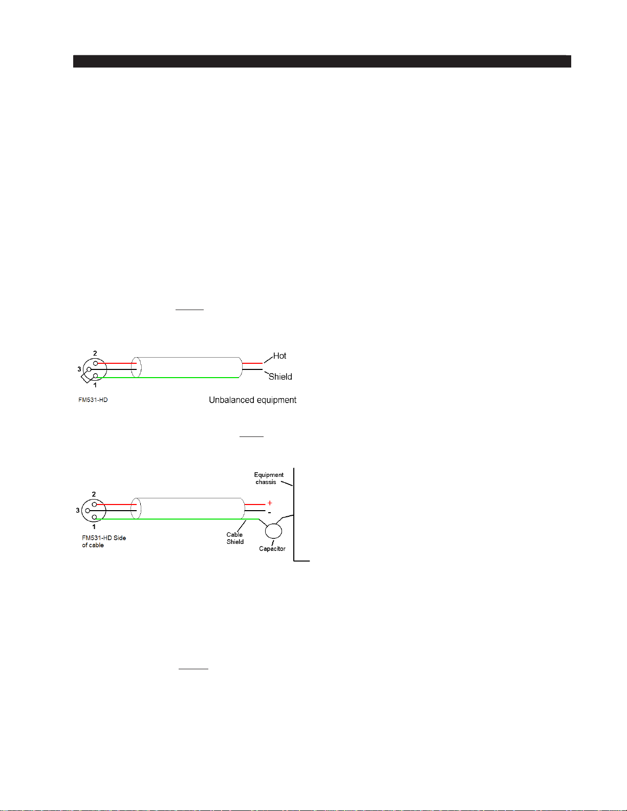
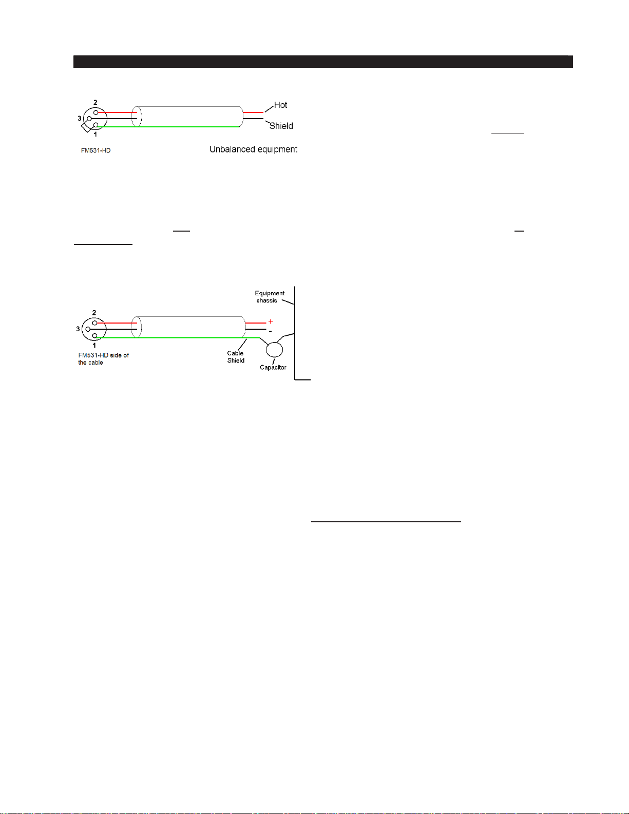
Unbalanced input audio connections
should be made with shielded two con-
ductor cable. At the unbalanced source’s
output connect its “+” output to processor’s
“Hi” (XLR pin 2) input and connect the
shield wire to the “Lo” (XLR pin 3) input. If the cable’s shield is used (recommended)
connect it at the hardware end only (XLR pin 1) to prevent AC ground loops.
If RF interference is an issue, the far
(oating and ungrounded) end of the
cable shield can be experimentally bypassed to RF ground via a 0.01µF, 250V
AC capacitor. Suitable capacitors are:
TDK CS17-F2GA103MYGS
Murata DE2F3KH103MA3B
Panasonic ECK-ATS103MF
AVX 65N103MBLCP
Field experience indicates that the listed capacitors can handle the reasonably high
RF currents that might exist on audio cable shields at AM and FM transmitter sites.
Analog Audio Output Connections
Balanced audio loads should be connected to processor’s outputs using standard
two-conductor shielded audio cable. Unbalanced audio loads should be avoided, but
if they can’t they should be connected using shielded two conductor cable such as
Belden 8451 or 9451 (as if connecting a balanced source).
The FM-531HD is equipped with active balanced output stages that behave like
a transformer. Because of this behavior the wiring may be different than expected.
FM-531HD / May 2013
page 1 – 5
Page 17
GENERAL INFORMATION
The unbalanced load’s “Hi” lead should
be connected to XLR connector Pin
2
(“Hi”). The unbalanced load’s shield
should be connected to the processor’s
output XLR Pin 3 (“Lo”). Then, and to
enable the processor’s balanced output amplier to operate correctly when driving the
unbalanced load it is recommended that the FM‑531HD XLR output Pin 1 (ground/
shield) also be connected to Pin 3 (“Lo”), noting that this MUST BE DONE at the
processor’s output connector (see the diagram above).
Note that it is not advisable to connect Pin 1 and Pin 3 conductors together at
the far end of the cable, as doing so can induce external noise and crosstalk on the
output amplier’s “load sense” lead which is XLR Pin 3 when Pin 2 is being used
as the “Hot.”
As in the input case, if RF interference
is an issue the far (oating) end of the
cable shield can be experimentally bypassed to RF ground through a 0.01µF
250V AC rated capacitor to see if it
helps. Please refer to the previous page
for a listing of capacitors known to be
effective in this task.
Digital Audio/ baseband192 Connections
For digital audio connections always use a good quality digital audio cable (or
twisted pair Category 5E/6 Network cable) having a characteristic impedance of
110 ohms. This cable should be shielded where possible, and in the case of multi‑pair
cable, each pair should be individually shielded. Foil shielding is recommended for
permanent installations, and a cable with foil shield plus an overall braid should be
used in applications where frequent exing of cables might occur.
Generic “audio” cable such as Belden 8451 and 9451 may sometimes be used for
interconnecting AES3 digital audio devices as long as the cable is short. The actual
cable length that will work satisfactorily is determined by many factors and may include the error correction and jitter tolerance of the AES3 receiver, the characteristics
of the digital cable driver and the characteristics of the specic cable being used and
its length. “Generic” analog audio cable typically has much higher capacitance than
digital cable, which can slow down the rise time of digital data signals, impairing the
ability of the AES3 receiver to accurately recover the digital signal without errors.
This can result in increased jitter, dropouts, or at the extreme, no audio at all.
FM-531HD / May 2013
page 1 – 6
Page 18

GENERAL INFORMATION
Where to Install the FM-531HD
The best location to install the FM‑531HD is at the transmitter site. This requires that
a discrete Left/Right STL, either analog or digital, be involved in the signal path. The
major benet of a transmitter site installation is that it enables the use of the FM‑531HD’s
built‑in lab‑grade stereo encoder which allows tighter control of modulation peaks.
A transmitter site location for the processor has the additional benet of allowing
the use of the FM‑531HD’s highly oversampled composite processor for an additional
loudness advantage. The composite clipper algorithm of the FM‑531HD is much cleaner
and more forgiving than those in other products, and in combination with the tight pilot
and SCA protection lters can create additional loudness without the audible grunge
that composite clippers typically create.
We recommend that whenever there is a choice between using an exciter’s com‑
posite MPX or AES3 input the processor (any processor) should be interfaced to the
transmitter using the exciter’s composite stereo multiplex input. The exciter’s AES3
digital input may be “clean” and it may be “digital”, but it also precludes the ability to
gain additional loudness through the use of the FM‑531HD’s intelligent oversampled
composite clipper. Also, depending on factors including the sample rates being used the
exciter’s AES digital input can exhibit inferior peak control compared to the exciter’s
composite input.
When the processor is located at the studio and an STL is being used to send the
program material to the transmitter site there are several issues to consider:
Analog Left/Right STL
Older analog discrete left/right STL’s can suffer from an inability to control audio
peaks because of inadequate bandwidth in their IF circuits and/or poor low frequency
and phase performance. Individual left/right STL’s rarely have identical group delay
and this will adversely affect stereo separation when the signal is nally converted to
the multiplex composite domain. Such STL’s can also suffer from AFC bounce when
handling highly processed low frequency material and this can rob modulation capabil‑
ity and therefore reduce on‑air loudness.
Composite Analog STL
A high quality analog composite STL can have advantages over an analog left/right
STL and can typically have broader audio bandwidth and better audio performance
than analog discrete STL’s. Most even have the capability to also piggyback subcarriers
such as SCA and RDS along with the composite audio. This means that most SCA and
RDS generators may also be located at the studio end of the STL, which, along with
the audio processor, makes for a very convenient setup. With a modern composite STL
and properly engineered point‑to‑point path, the audio can be nearly as transparent as
a digital STL.
Analog Phone Lines
Discrete left/right analog “phone line” STL’s are not recommended because of the
inability of most Telco service providers to meet the at frequency response and phase
matching requirements of the pair of audio circuits. Furthermore, in many countries
wideband analog circuits have become unavailable or their cost prohibitive. On the other
hand if the “wired” STL is a dedicated (and equalized if necessary) pair of circuits that
is under the station’s full control they may be acceptable.
FM-531HD / May 2013
page 1 – 7
Page 19

GENERAL INFORMATION
Digital STL
There are two categories of Digital STL’s on the market – those with codec-based
audio compression and those with uncompressed linear audio.
When a digital STL employing codec-based audio compression is being used, the
processor should be located at the transmitter site which places it after the codec. The
reason for this is that most codecs will sound better when presented with unprocessed
studio audio instead of highly processed and pre-emphasized audio from the processor’s output. Further, the encoding schemes used in such STL’s cannot accurately pass
the well-dened peak levels created by the FM-531HD, which can create a modulation
(loudness) disadvantage.
Installing the processor at the studio end of a “compressed” STL brings with it at
least two caveats:
- The stereo generator and composite clipper inside the FM-531HD will not be available. Many digital exciters offer stereo generator and composite clipper functions,
but their clippers have historically been quite crude compared to the exceptional
clipper in the FM-531HD. Therefore “exciter hosted” composite clippers are not
the optimum choice when the station’s ultimate sound quality is important.
- Compressed STL’s do not perform well when presented with competitively
processed audio, especially when that audio is pre-emphasized. The reason for
this is because codecs do their work by examining the audio for opportunities to
remove content that shouldn’t be audible to the average human ear. When densely
processed audio is presented to a codec there are fewer “opportunities” for it to
remove redundant audio information and most importantly, then mask that removal
from our hearing so that we don’t notice it. When handling heavily processed
(limited dynamic range) material codec operation is usually much more obvious
– even to the point of being objectionable – than when the processing is located
after the codec where the “masked” artifacts are only occasionally and usually
minimally unmasked by “processing gain.”
Uncompressed (linear) digital STL’s have only one major installation limita-
tion – placing the processor at the studio end of the STL will preclude the use of
the stereo generator and composite clipper.
TIP: If using the FM-531HD at the studio be certain that any clippers in the ste-
reo generator at the transmitter site are properly set up to complement the settings
in FM-531HD. This will prevent gross distortion and potentially large modulation
overshoots.
Where Should Pre-Emphasis Go?
Pre-emphasis should always be applied by the audio processing, not the exciter.
Modern FM audio processors have highly sophisticated technology to deal with the
challenges presented by FM pre-emphasis curve and can provide very tight modulation
control with very low perceived distortion. FM exciters do not have this technology.
The best location for the audio processor from an overall performance standpoint
is always at the transmitter.
FM-531HD / May 2013
page 1 – 8
Page 20

GENERAL INFORMATION
Arbitron People Meter (PPM)
Field experience has been that Wheatstone audio processors favorably passes the
data watermarking scheme used in the Arbitron People Meter rating service technol‑
ogy, regardless of the aggressiveness of the processing being performed.
AC Power Considerations
Please note that in order to enhance its long‑term reliability, the FM‑531HD has no
power switch (switches usually become intermittent over time without regular use).
The FM‑531HD accepts AC line input voltages between 90 and 260 VAC, 50 or
60Hz. Power consumption is under 100VA.
Although aggressive AC input ltering is utilized on the AC power input it is al‑
ways advisable to use external surge protection and an uninterruptible power supply
(UPS) wherever possible, especially where the AC power quality can be in question,
such as at a remote transmitter site.
Power conditioning, surge suppression, and even power backup devices are wise
investments when using sensitive modern electronic devices. The FM‑531HD is, after
all, a highly specialized “computer.”
The use of a UPS (uninterruptible power supply) is usually recommended and will
protect the FM‑531HD from short duration power interruptions and glitches which
might otherwise signal it to reboot. When the FM‑531HD reboots there will be a loss
of audio for approximately 15 seconds.
FM-531HD / May 2013
page 1 – 9
Page 21
GENERAL INFORMATION
Front Panel Interface
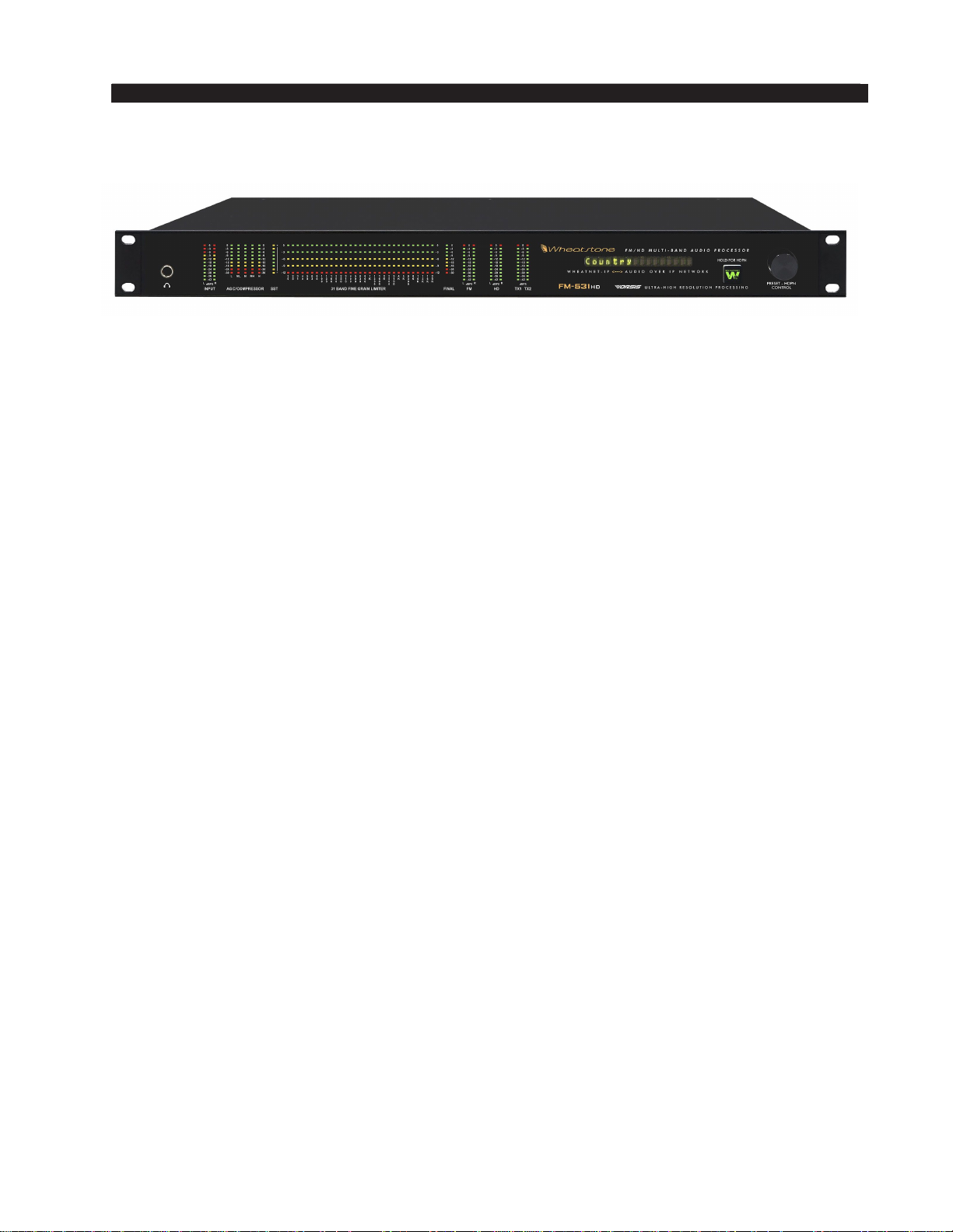
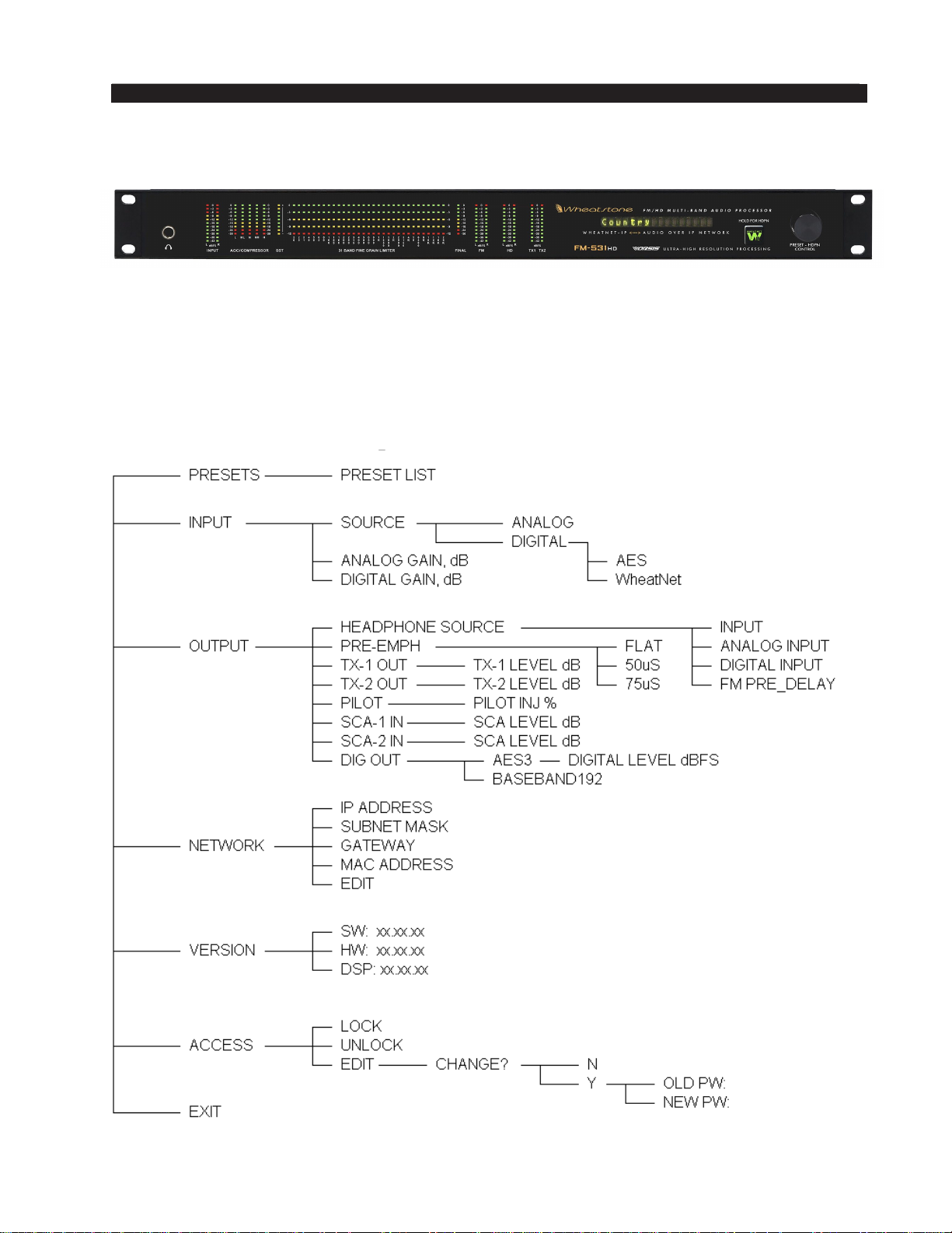
In addition to the comprehensive LED metering display, the front panel also hosts a
dot matrix display that shows the current preset on the processor as well as a jog wheel,
take button and headphone jack. The jog wheel allows the user to scroll and take presets
as well as adjust input and output levels and composite level, and access other menu
options like headphone volume control for the front panel jack.
FM-531HD Front Panel Navigation
FM-531HD / May 2013
page 1 – 10
Page 22

GENERAL INFORMATION
Basic Setup
Once the processor is rack mounted and connected to a clean source of AC power
it is ready for operation. Basic setup and adjustment may be accomplished using the
front panel and adjustments to the input and output and preset takes may be made. To
tailor the sound of a preset, the GUI interface running on a Windows PC will be needed.
The setup procedure that follows uses the front panel controls.
• Connect the Analog or Digital audio inputs as appropriate for your installation.
• Select the main input source (Analog or Digital). Digital may be via XLR AES
or optional WheatNet‑IP.
• While in the <INPUT> menu and observing the Input meters, adjust the Input Gain
control (Digital or Analog as appropriate) until the input meters are just peaking at
-12dBFS with normal program levels coming from the studio or program source.
Setting input levels correctly is an important step towards getting the best audio
performance from the FM-531HD audio processor. Note that the input meters
are sample-accurate and include peak (dot) over average (bar) displays, and it is
normal to see the average levels reading quite low (perhaps below -20dBFS) when
feeding the processor with unprocessed audio.
• For best overall audio chain performance, the Input of the FM-531HD should be
calibrated so that it reaches 0dBFS when the signal chain prior to the processor
reaches its 0dBFS, or digital full scale level. This aligns the overload point of the
audio chain prior to the processor for maximum headroom and best signal to noise.
• Set the Pre-Emphasis to the value that is appropriate for your region. Note that
if pre-emphasis has been enabled in the Input menu all FM outputs will be preemphasized unless De-Emphasis for that output is explicitly selected.
• Now make the audio output connections appropriate for your installation, noting
that the Analog and Digital outputs may be used simultaneously.
• The FM-531HD is shipped with the analog output set for MPX. This means that
the two BNC female connectors (TX-1 and TX-2) plus the analog XLR connec‑
tors (Left or Right) may be used for composite operation. To use these outputs in
other modes (L/R or L/R de-emphasized) you must connect to the processor using
the supplied GUI on a Windows PC. Adjust the TX outputs as needed for 100%
modulation. This should be done with normal programming and not test tones.
The RMS level of alignment tones does not crest at 100%. It may take a minute
or so with minor adjustments to nd a good starting point based on the music/
speech programming being fed to the processor. The default setting is +2.40dB
and is calibrated this way to drive the default levels on most exciters.
• If using the AES Digital Output, connect it to the equipment following the
FM-531HD and adjust the AES Output level control in the Output Menu as ap‑
propriate for your installation.
• If using the digital baseband192 output, modulation levels into the exciter are
controlled by the TX-1 and TX-2 level controls. Currently only the TX-1 signal
is supported by transmitter manufacturers.
• The FM-531HD Audio Processor factory default preset is called Quick Start.
We recommend using this preset as a starting point for aligning and putting the
processor on the air. Once the processor is actually on the air, you may scroll thru
the list of presets to nd one that best represents the format of the station. To do
FM-531HD / May 2013
page 1 – 11
Page 23

GENERAL INFORMATION
this, scroll to <PRESET> and press the enter key. To activate a preset, simply press
the enter key or the jog wheel once the preset you wish to listen to is displayed.
NOTE: Preset names don’t necessarily mean that the preset can or should ONLY
be utilized for a program format with a similar name. It is advisable to listen to
each preset to see how it sounds on your station, in your market, and with your
program material.
• If you are in a region that requires the use of the BS412 limiter (some European
countries), you may control the behavior of the limiter from the front panel. How‑
ever, you cannot activate the limiter (or deactivate it) from the front panel. You
will need to connect with the supplied GUI to do this. The BS412 limiter control
can be found under the <OUTPUT> part of the menu.
You’re on the air!
NOTE: Detailed information on the particulars of the GUI application on
the front panel can be found in the following chapter which also cover the
operation of the PC-based Guru GUI application.
FM-531HD / May 2013
page 1 – 12
Page 24
GENERAL INFORMATION
Rear Panel Connections
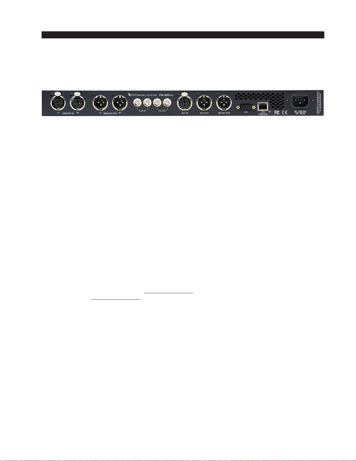
The image below shows the rear panel of the FM‑531HD and the location of vari‑
ous connectors associated with an installation:
All audio input and output, control, Ethernet, and power supply connections are
made via connectors on the processor’s rear panel.
The FM‑531HD’s rear panel connectors from left to right are:
Analog Left Channel In
Analog Right Channel In
Analog Left Channel Out*
Analog Right Channel Out*
SCA-1 Input
SCA-2 Input
TX-1 Out
TX-2 Out
AES Digital Input
AES Digital/baseband192 Out
HD AES Digital Out
GPI Input
Ethernet Control/WheatNet-IP Interface
IEC Standard male AC Power Input
* When FM-531HD’s output mode is set to Composite Multiplex, the Analog left and right output XLR connectors emit a balanced Composite Multiplex signal. A balanced signal is preferred when interfacing with exciters
having a floating and differential MPX input (most modern exciters do) and can provide a lower overall noise
floor than an unbalanced MPX circuit.
The listed connections are made via various connectors mounted on the FM‑531HD’s
rear panel.
• Seven XLR connectors are provided for analog and digital audio input and output
connections.
• Four BNC connectors are provided for SCA inputs and TX (transmitter) out, or
Composite Multiplex (MPX) connections.
• One RJ-45 connector is provided for Ethernet connection and WheatNet IP audio
streaming.
• One DB-9 connector provides 8 GPI inputs (for selecting presets in the rst eight
storage slots). The pinout drawings in the Appendix summarize wiring connections
for these features.
FM-531HD / May 2013
page 1 – 13
Page 25

GENERAL INFORMATION
Audio Inputs
The FM‑531HD accepts three types of audio input sources:
• Balanced analog line level left/right audio;
• Digital AES3 compliant left/right audio with sample rates between 32kHz and 96kHz;
• Optional WheatNet‑IP via 100BaseT Ethernet connection to a WheatNet‑IP audio
network.
Input audio can be applied to all inputs simultaneously.
Automatic audio failover from analog to digital or vice versa is supported.
Automatic failover from AES3 or WheatNet‑IP to analog is instantaneous and based
on invalid or missing bits in the AES3 or WheatNet‑IP stream, or after 30 seconds of
“silence” (level below ‑48dBFS).
Automatic failover from analog to AES3 is based on silence sense responding to audio
on both channels being below ‑48dBFS for more than 30 seconds.
Failover from AES3 to WheatNet‑IP (or vice versa) is not available.
Analog In – XLR-F
Pin 1 XLR LT SH – LINE LT IN SH
Pin 2 XLR LT HI – LINE LT IN HI
Pin 3 XLR LT LO – LINE LT IN LO
Pin 1 XLR RT SH – LINE RT IN SH
Pin 2 XLR RT HI – LINE RT IN HI
Pin 3 XLR RT LO – LINE RT IN LO
AES In – XLR-F
Pin 1 XLR SH – AES IN SH
Pin 2 XLR HI – AES IN HI
Pin 3 XLR LO – AES IN LO
SCA In – BNC
Pin 1 BNC 1 HI ‑ SCA 1 IN HI
Pin 2 BNC 1 SH ‑ SCA 1 IN SH
Pin 1 BNC 2 HI ‑ SCA 2 IN HI
Pin 2 BNC 2 SH ‑ SCA 2 IN SH
FM Audio Outputs
Output audio for the FM path is available as:
• Balanced analog left/right stereo, pre‑emphasized.
• Balanced analog left/right stereo, de‑emphasized according to pre‑emphasis in use.
• AES3 digital, either pre or post diversity delay, and/or de‑emphasized according to
pre‑emphasis in use.
• Balanced line level composite stereo multiplex on male XLR connectors.
• Unbalanced composite stereo on two BNC female connectors.
• WheatNet‑IP audio network.
FM-531HD / May 2013
page 1 – 14
Page 26

GENERAL INFORMATION
Analog Out – XLR-M
Pin 1 XLR LT SH – LINE FM LT OUT SH
Pin 2 XLR LT HI – LINE FM LT OUT HI
Pin 3 XLR LT LO – LINE FM LT OUT LO
Pin 1 XLR RT SH – LINE FM RT OUT SH
Pin 2 XLR RT HI – LINE FM RT OUT HI
Pin 3 XLR RT LO – LINE FM RT OUT LO
AES / baseband192 Out – XLR-M
Pin 1 XLR SH – AES FM / BASEBAND192 OUT SH
Pin 2 XLR HI – AES FM / BASEBAND192 OUT HI
Pin 3 XLR LO – AES FM / BASEBAND192 OUT LO
TX Out – BNC
Pin 1 BNC 1 HI – TX 1 OUT HI
Pin 2 BNC 1 SH – TX 1 OUT SH
Pin 1 BNC 2 HI – TX 2 OUT HI
Pin 2 BNC 2 SH – TX 2 OUT SH
HD Audio Outputs (optional)
The optional HD audio output is available as AES on a male XLR connector on
the rear of the FM‑531HD.
HD AES Out – XLR-M
Pin 1 XLR HD SH – AES HD OUT SH
Pin 2 XLR HD HI – AES HD OUT HI
Pin 3 XLR HD LO – AES HD OUT LO
Headphone Monitoring
An overload protected stereo headphone amplier drives the front panel ¼" stereo
headphone output located on the left side of the processor’s front panel. The audio
source feeding the headphones may be chosen from several signal points within the
processing algorithms, including both analog and digital inputs, even if those inputs
have not been selected to feed the audio processing chain. The System menu of the
GUI hosts the headphone router selector.
FM-531HD / May 2013
page 1 – 15
Page 27

GENERAL INFORMATION
C
C
C
C
C
C
C
C
C
C
C
C
Network Connection
The FM‑531HD audio processor has a 100Base‑T Ethernet port on the rear
panel. The port is Auto‑MDIX, allowing it to support straight through and cross‑
over cables. The Ethernet interface can support up to four simultaneous connec‑
tions to remote GUIs.
Networked systems are normally connected to the FM‑531HD via “straight”
(pin to pin) CAT5 cable. For typical CAT5 cable pinouts see below. These con‑
nections are for communicating with the conguration computer via a network.
If you are connecting directly between the computer and the FM‑531HD with
no network in between, it is normal to use a crossover cable.
Ethernet – RJ-45
Pin 1 – TXD +
Pin 2 – TXD ‑
Pin 3 – RXD +
Pin 4 – N/C
Pin 5 – N/C
Pin 6 – RXD ‑
Pin 7 – N/C
Pin 8 – N/C
Typical Ethernet Cable
PIN
TXD +
TXD -
RXD +
N/
N/
RXD -
N/
N/
RJ-45
Plug
White/Orange
Orange
White/Green
Blue
White/Blue
Green
White/Brown
Brown
1
2
3
4
5
6
7
8
Typical Crossover Cable
PIN
TXD +
1
TXD -
2
RXD +
3
N/
4
N/
5
RXD -
6
N/
7
N/
8
RJ-45
Plug
White/Orange
Orange
White/Green
Blue
White/Blue
Green
White/Brown
Brown
RXD +
RXD -
TXD +
N/
N/
TXD -
/
N
N/
PIN
White/Orange
1
Orange
2
White/Green
3
Blue
4
White/Blue
5
Green
6
White/Brown
7
Brown
8
PIN
White/Green
1
Green
2
White/Orange
3
Blue
4
White/Blue
5
Orange
6
White/Brown
7
Brown
8
RJ-45
Plug
RJ-45
Plug
FM-531HD / May 2013
page 1 – 16
Page 28

GENERAL INFORMATION
General Purpose Interface (GPI)
The FM‑531HD is equipped with eight General Purpose Input (GPI) control input
ports on the rear female DB‑9 connector. All GPI connections are optically‑isolated
to prevent external ground loops and to prevent dangerous voltages from being intro‑
duced into the processor. Further, the GPI inputs accept DC voltages of either polarity,
easing interfacing in the eld.
The eight GPI inputs are hard‑coded in software to activate the rst eight preset
slots.
GPI
The GPI interface provides eight separate General Purpose Inputs, sharing a com‑
mon return. The connector is a female DB‑9 connector with the following pin assign‑
ments. Note that all pins are isolated from FM‑531HD internal circuitry!
Pin 1 – GPI COM (‑)
Pin 6 – GPI 1 IN (+)
Pin 2 – GPI 2 IN (+)
Pin 7 – GPI 3 IN (+)
Pin 3 – GPI 4 IN (+)
Pin 8 – GPI 5 IN (+)
Pin 4 – GPI 6 IN (+)
Pin 9 – GPI 7 IN (+)
Pin 5 – GPI 8 IN (+)
Processing Presets
The FM‑531HD audio processor comes equipped with several dozen factory presets
and can hold a total of 80 presets in its onboard memory. Additional customer‑created
presets may be saved within the processor’s onboard memory until all preset storage
slots are full. An unlimited number of presets can be stored on the PC that hosts the
Windows‑based remote control GUI software.
In order to prevent clicks and pops when presets are changed, preset parameters are
slewed between the current parameter values and those of the new preset whenever a
new preset is taken. Because of this, when changing presets, especially between pre‑
sets that are tuned quite differently, it may take several seconds for the new settings to
completely settle in. It is important to remember this concept; the FM‑531HD’s preset
switching is designed to make it as unobtrusive as possible and therefore parameter
changes are not instantaneous. This factor must be taken into consideration whenever
switching between presets in order to compare them!
When a preset has been recalled and has not been modied the preset’s name is
displayed in green text within the GUI’s current preset window. If changes to the pre‑
set have been made its name will be displayed in red text instead of green. Once the
modied settings have been saved back to the processor’s hardware the preset name
will again be displayed in green.
Factory pre‑sets can be readjusted and saved to new names in order to create a
completely different air sound. The factory presets are write‑protected and changes
made to them cannot be written back to the same memory location. Factory presets
FM-531HD / May 2013
page 1 – 17
Page 29

GENERAL INFORMATION
that have been modied are considered by the system to be “user” presets and therefore
must be saved as a new name and in a new preset storage slot.
Our advice is to start with a factory preset that has the on air sound that is closest
to what you believe you need. If changes are necessary, the best approach is to make
small changes, one or two at a time, and then listen for quite a while before deciding
that more changes are necessary. A consultant friend of ours advises: “Tweak small
and then listen large.”
NOTE:
User presets that have been stored in preset slots 1 through 8 are logically assigned
to the eight remote GPI functions. Examples of presets that might be stored here are:
‑ A preset that has all processing turned off and/or has special input/output level
calibrations (such as for testing).
‑ A preset that has all processing enabled but has the Stereo Pilot turned off (a Mono
Preset).
‑ A preset that changes the input or output source or level calibrations (note: “System
Settings Change with Preset Takes” must be enabled in the System screen of the
GUI in order for presets to control I/O settings.
Preset storage is as follows:
‑ Preset slots 1 ‑ 8 are for user presets that can be selected by the optoisolated GPI
interface.
‑ Factory presets are installed beginning with a BYPASS stored in slot #9. Factory
presets cannot be written over or deleted.
‑ User presets, other than the GPI selectable presets in slots 1 through 8, are stored
above the highest‑numbered factory preset. The number of available slots for user
presets depends on how many factory presets were installed, which can vary with
software version. The total number of presets on the processor’s hardware cannot
exceed eighty (80). The storage space available for presets on the GUI’s host PC
(because of a preset’s tiny le size) is virtually unlimited.
‑ User presets may be locked at the user’s discretion to prevent inadvertent changes.
Any user can unlock user‑locked presets.
FM-531HD / May 2013
page 1 – 18
Page 30

GENERAL INFORMATION
Analog XLR Connections
Analog In - XLR-F
XLR LT-F
2
3
1
XLR RT-F
2
3
1
XLR LT-M
PIN 1 XLR LT SH - LINE LT IN SH
PIN 2 XLR LT HI - LINE LT IN HI
PIN 3 XLR LT LO - LINE LT IN LO
PIN 1 XLR RT SH - LINE RT IN SH
PIN 2 XLR RT HI - LINE RT IN HI
PIN 3 XLR RT LO - LINE RT IN LO
Analog Out - XLR-M
FM-531HD / May 2013
1
3
2
XLR RT-M
1
3
2
PIN 1 XLR LT SH - LINE FM LT OUT SH
PIN 2 XLR LT HI - LINE FM LT OUT HI
PIN 3 XLR LT LO - LINE FM LT OUT LO
PIN 1 XLR RT SH - LINE FM RT OUT SH
PIN 2 XLR RT HI - LINE FM RT OUT HI
PIN 3 XLR RT LO - LINE FM RT OUT LO
page 1 – 19
Page 31

GENERAL INFORMATION
Digital XLR Connections
AES In - XLR-F
XLR-F
2
3
1
PIN 1 XLR SH - AES IN SH
PIN 2 XLR HI - AES IN HI
PIN 3 XLR LO - AES IN LO
AES Out / baseband192 - XLR-M
XLR-M
1
3
2
PIN 1 XLR SH - AES FM / BASEBAND192 OUT SH
PIN 2 XLR HI - AES FM / BASEBAND192 OUT HI
PIN 3 XLR LO - AES FM / BASEBAND192 OUT LO
AES HD Out - XLR-M
FM-531HD / May 2013
XLR HD-M
1
3
2
PIN 1 XLR HD SH - AES HD OUT SH
PIN 2 XLR HD HI - AES HD OUT HI
PIN 3 XLR HD LO - AES HD OUT LO
page 1 – 20
Page 32

GENERAL INFORMATION
BNC Connections
BNC - SCA
BNC - TX
1
2
1
2
PIN 1 BNC 1 HI - SCA 1 IN HI - CENTER PIN
PIN 2 BNC 1 SH - SCA 1 IN SH - SHELL
PIN 1 BNC 2 HI - SCA 2 IN HI - CENTER PIN
PIN 2 BNC 2 SH - SCA 2 IN SH - SHELL
PIN 1 BNC 1 HI - TX 1 OUT HI - CENTER PIN
PIN 2 BNC 1 SH - TX 1 OUT SH - SHELL
PIN 1 BNC 2 HI - TX 2 OUT HI - CENTER PIN
PIN 2 BNC 2 SH - TX 2 OUT SH - SHELL
FM-531HD / May 2013
page 1 – 21
Page 33
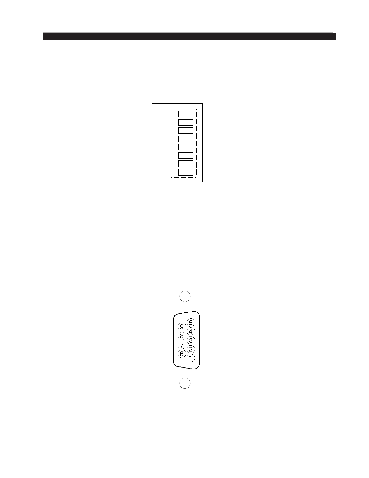
GENERAL INFORMATION
Ethernet - RJ-45
RJ-45 ETH
1
2
3
4
5
6
7
8
TXD +
TXD RXD +
N/C
N/C
RXD N/C
N/C
General Purpose Interface - DB-9
GPI - DB-9
FM-531HD / May 2013
GPI 7 IN (+)
GPI 5 IN (+)
GPI 3 IN (+)
GPI 1 IN (+)
GPI 8 IN (+)
GPI 6 IN (+)
GPI 4 IN (+)
GPI 2 IN (+)
GPI COM (-)
page 1 – 22
Page 34

FM-531HD GURU GUI
PC Based
Audio Processing Guru
®
GUI
Chapter Contents
Installation ......................................................................................2-3
Changing FM-531HD’s IP Address Configuration ...................... 2-5
Reconfiguring The Remote GUI ...................................................2-6
Connecting Directly Without a LAN ............................................. 2-6
About DHCP and FM-531HD ......................................................... 2-6
FM-531HD’s Ethernet Ports and Network Protocols .................. 2-6
If the GUI “Connected” But the Meters and Analysis Displays
Don’t Work ..................................................................................................................2-7
Using Guru GUI ..............................................................................2-8
Input Menu .................................................................................................................2-9
Input Source ............................................................................................................2-9
Audio Input Signal Presence Indicators ..................................................................2-9
Automatic Input Failover .........................................................................................2-9
Analog Gain ............................................................................................................2-10
Digital Gain .............................................................................................................2-10
L/R Balance ............................................................................................................2-10
Output Menu .............................................................................................................2-10
Stereo Encoder Menu ...............................................................................................2-11
MPX Processor Style ..............................................................................................2-11
MPX Process Control .............................................................................................2-12
BS412 MPX Power Controller ................................................................................2-12
Pilot Injection ..........................................................................................................2-13
Emphasis ................................................................................................................2-13
SCA-1 and SCA-2 Inputs .......................................................................................2-13
TX-1 and TX-2 Outputs ..........................................................................................2-13
Presets Menu ............................................................................................................2-14
Selecting a Preset ..................................................................................................2-14
Saving a Preset ......................................................................................................2-14
Preset Library Functions ........................................................................................2-14
Locking Presets ..................................................................................................2-15
How to View Preset Changes .............................................................................2-15
Quick Save .............................................................................................................2-16
System Menu ............................................................................................................2-17
Input/Output Settings Change With Presets ..........................................................2-17
Metering Data via TCP/IP .......................................................................................2-17
FM-531HD / May 2013
page 2 – 1
Page 35

FM-531HD GURU GUI
Headphone Source ................................................................................................2-18
Headphone Volume Control ...................................................................................2-18
Status Indicators ....................................................................................................2-18
Temp ................................................................................................................... 2-18
Analog ................................................................................................................2-18
Digital .................................................................................................................2-18
Remote Login .........................................................................................................2-19
Events .....................................................................................................................2-19
Creating a Weekly Rotation Schedule ................................................................2-19
Creating a Long Term Rotation Schedule .......................................................... 2-20
Deleting a Scheduled Event ...............................................................................2-20
Setting System Time ..............................................................................................2-21
SNTP (Simple Network Time Protocol) ..............................................................2-21
Sound Menu.. ............................................................................................................2-22
FM Sound Adjust ....................................................................................................2-22
AGC Depth .........................................................................................................2-22
Compression ......................................................................................................2-22
Density ................................................................................................................2-23
Low/Warm EQ ....................................................................................................2-23
Mid/High EQ .......................................................................................................2-23
Loudness ............................................................................................................2-23
HD Sound Adjust ....................................................................................................2-24
Density ................................................................................................................2-24
Low/Warm EQ ....................................................................................................2-24
Mid/High EQ .......................................................................................................2-24
Loudness ............................................................................................................2-24
Audio Input and Output Metering.. ............................................................................2-25
Audio Processing Gain Reduction Displays.. ............................................................2-26
Analysis Menu... ........................................................................................................2-27
FFT .........................................................................................................................2-27
O-Scope .................................................................................................................2-28
E vs. F .....................................................................................................................2-28
3-D Plot ..................................................................................................................2-29
SDR™ .....................................................................................................................2-29
A-Clip .....................................................................................................................2-29
Accessing Menu Options.. ........................................................................................2-30
FM-531HD / May 2013
page 2 – 2
Page 36
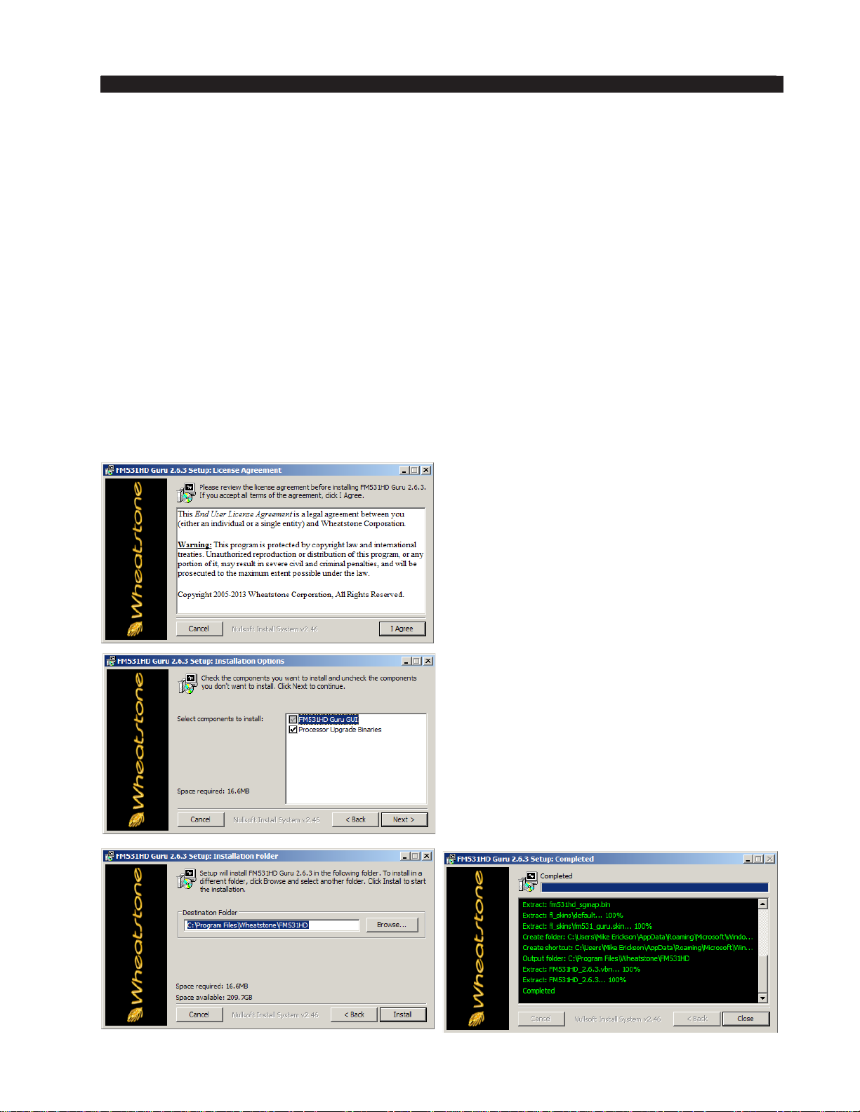
FM-531HD GURU GUI
PC Based
Audio Processing Guru
®
GUI
Installation
The Audio Processing Guru® software may be installed on any Windows-based PC
running Windows 2000 Service Pack 2 or later. Installation is virtually identical across the
various Windows operating systems and in general is as follows:
• Place the CD containing the FM‑531HD software in the PC’s CD drive and close the
tray.
• Navigate to the CD drive using either Windows Explorer or through My Computer.
• Locate the le on the CD called “FM531HD_Guru_x_x_x.exe” where x_x_x denotes
the software version number. Then…
Double click on this le and the installer will start, followed by the welcome screen
shown below.
Click on “I Agree” and the installer will
present a new prompt asking for what les
to install. Leave all check marks selected
and press the Next button to proceed.
Next the installer will ask where to install the GUI. The default is: C:\Program
Files\Wheatstone\FM531HD.
The GUI does not modify the registry
and does not require external drivers.
Therefore it can be run from any folder,
including directly from a USB thumb drive!
When the installer has nished placing
the les in the chosen locations a “Completed” status will be shown. Click the
Close button to close the installer.
FM-531HD / May 2013
page 2 – 3
Page 37
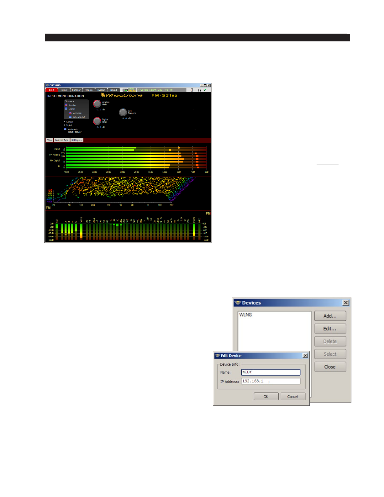
FM-531HD GURU GUI
The GUI may now be started by selecting it from within the PC’s Start Menu Programs
list. Once the GUI starts it will appear as below, minus the metering and analysis activity
shown below because we haven’t yet connected the GUI to the FM-531HD!
In order to communicate with
FM-531HD the following conditions
must be met.
1. The PC has an Ethernet interface
and a cable is connected between it
and FM-531HD (a crossover cable
is NOT required).
2. The PC’s network interface is
enabled and is congured to be
on the same IP address subnet
as FM-531HD. The default IP
addresses for FM-531HD are
192.168.1.200 for hardware and
192.168.1.201 for the front panel.
These addresses cannot be used for
the PC hosting the remote GUI.
3. The FM-531HD is already powered
up and the front panel displays are
nished initializing and the screens
are active.
Once all of the above is in place, the GUI must be congured to talk to the FM‑531HD.
1. Place the mouse cursor in the upper part of the screen (where the controls are) and right
click. A popup menu appears. Mouse over the word Hardware on this menu and another
popup appears with the item Devices... at the top of the list. Select Devices... and the
Devices dialog appears.
In the event no FM-531HD units are listed, or
one is adding a further device, or adding one
for the rst time, Add brings up the Edit Device
dialog box, which asks for the new prospect’s
name and IP address.
2. In the Edit Device dialog we can give each
FM-531HD a unique name. We suggest naming each processor, perhaps using the station’s
call sign.
3. Enter 192.168.1.200 in the IP Address eld and
click OK. The Edit Device dialog will close. With
the new device in the list highlighted, click on
the Select button of the Device dialog.
Once the Edit Device dialog closes, when the GUI’s Online button is clicked (to the right
of the Sound tab) the status indicator should change to say Online and the FM-531HD’s
name should appear inside the Device window underneath the Online status.
If the FM-531HD will be staying on its default IP address no other steps need to be
taken. If the IP address conguration needs to change to match the local network’s environment, please see the next section for how to accomplish those changes.
FM-531HD / May 2013
page 2 – 4
Page 38

FM-531HD GURU GUI
Changing FM-531HD’s IP Address Configuration
The FM‑531HD’s pre‑congured factory default Ethernet Conguration is as follows:
Hardware IP Address: 192.168.1.200
Subnet Mask: 255.255.255.0
Gateway: 192.168.1.1
The FM‑531HD’s network conguration can be viewed or changed using the front
panel and scrolling to <NETWORK> and hitting the enter key.
You can then view the four setting congurations:
Hardware IP Address – This is the address of the FM‑531HD’s DSP farm and is the
address that the remote GUI running on a host computer uses to connect to in order to
control the FM‑531HD. Clear this dialog box by backspacing over the existing address
and then enter the new address using the decimal point button to jump from octet to
octet within the IP address box.
Subnet Mask – The subnet mask entry must be appropriate for the network being
used. Please see your local IT person if this item causes confusion, or consult one of
the free online resources such as http://www.subnetmask.info/ or http://www.subnetcalculator.com/.
Gateway – This is the gateway address that the FM‑531HD will use to reach con-
nections outside of its own internal network. If you are on a local LAN segment or
connected to the FM‑531HD by a direct connection, the Gateway address is not usually
necessary and can be set to either 0.0.0.0 or 255.255.255.255. Note that this choice
appears to be a bit “Windows‑dependent” and therefore dependent on the host PC be-
ing used.
After determining the IP address that you wish the FM‑531HD to use, enter that
address in the FM‑531HD’s Hardware IP address eld using the navigation buttons. It
is always a good idea to clear the entire IP address eld rst before entering new data to
ensure there will be no hard to see leading or training blanks in the address. Always use
the decimal point button to navigate to the position of the next network address octet.
MAC Address – The MAC Address is a unique identier for the processor hardware
on your network. It is specic to your device and different from any other device on
the network. The MAC address of the FM‑531HD audio processor cannot be changed.
After viewing the settings above, there will be an option to <Edit..> the settings if
changes are needed. If you need to edit the settings:
• Scroll to the <Edit..> option on the dot matrix display
• The rst eld of numbers will blink on the <IP> eld. Using the jog wheel, in-
crease or decrease the numbers until they are at the correct value. Pressing the
enter key will move you along to the next set of numbers. Repeat until the IP
address is correct.
When the IP address is complete, the next set of addresses (Subnet) will appear for
editing. If you need to edit this eld, repeat the steps above. If not, simply press the
enter key to move thru the elds until you get to the nal set of addresses (Gateway).
Again, you have the option of editing or just pressing the enter key to bypass each eld.
At the end of the menu, the box will conrm any changes by displaying <Okay>.
FM-531HD / May 2013
page 2 – 5
Page 39

FM-531HD GURU GUI
Reconfiguring The Remote GUI
If the IP addresses of the FM‑531HD have been changed from those congured
in the remote GUI a few pages ago it will be necessary to go back into the GUI con-
guration and change the IP address for the FM‑531HD device that was originally
congured for the remote GUI. Here is how to do that…
Right click in the controls area of the remote GUI to activate the drop down menu
and select the Devices option under Hardware. When the Edit Device dialog opens
highlight the FM‑531HD device that was created earlier and click on Edit. Then modify
the IP address so that it perfectly matches the new hardware IP address just given to
the FM‑531HD hardware and then click OK.
Assuming that a good network path exists between the host PC (don’t forget to
change its address too if the IP address subnet has changed!) the GUI should be able
to go online to the FM‑531HD by clicking on the Online button at the top of the GUI.
When the status indicates Online the GUI is communicating with the FM‑531HD.
Connecting Directly Without a LAN
You can work without a LAN by connecting the FM‑531HD and the PC Ethernet
ports together with a standard Ethernet cable – either a straight through or crossover
cable may be used – the FM‑531HD’s Ethernet interface ports are Auto MDIX.
NOTE: The controlling PC and FM‑531HD’s network settings must be congured
to place them both on the same subnet! Although the network subnet can be any one
that is valid, both local and remote devices must be on the same subnet in order to
communicate.
Example:
If the FM‑531HD is using the 192.168.1.x address range and a laptop is using the
172.68.122.x address range the laptop will not be able to communicate with FM‑531HD.
The laptop will need an IP address conguration that puts it on the same 192.168.1.x
network subnet as the FM‑531HD.
About DHCP and FM-531HD
The FM‑531HD does not utilize nor support Dynamic Host Conguration Protocol (DHCP, or automatically assigned network addressing) – and needs to be assigned
“STATIC” network‑unique IP addresses.
FM-531HD’s Ethernet Ports and Network Protocols
The FM‑531HD uses both TCP and UDP protocols to communicate with the remote
GUI. The TCP protocol is used between the GUI to the FM‑531HD for control functions. TCP’s high reliability (due to handshaking) ensures that control changes sent to
the The FM‑531HD by the GUI will be received without errors.
Metering data is not at all critical, and only the differences between past and next
meter values are sent. Therefore a “no‑handshaking” protocol, UDP, is used to send
metering and other real time data back to the GUI. Dropped or corrupted packets will
have little visual effect on the metering and analysis displays, and the lack of (or no
need for) handshaking drastically reduces the amount of network bandwidth that is
required in order to run the GUI’s remote meters and analysis displays.
FM-531HD / May 2013
page 2 – 6
Page 40

FM-531HD GURU GUI
The FM‑531HD’s TCP protocol utilizes a xed port, port 55900 for control. The
FM‑531HD uses UDP for metering and tries to open port 60000 rst. If port 60000
is not busy, it uses it. If UDP port 60000 happens to be busy, UDP port 60001 is tried
next. This process continues until either an idle UDP port is found or the search stops
at UDP port 60010.
NOTE: The above reference ports must be open for any through‑the‑rewall connectivity. This also includes the Windows rewall on the host PC that is running the
GUI software – it must have these ports open too.
If the GUI Is “Connected” But the Meters and Analysis
Displays Don’t Work
Occasionally a network or internet service provider will block UDP trafc. When
that happens the GUI will connect to the FM‑531HD and the FM‑531HD can be controlled, but no metering or analysis graphics will be displayed. Fortunately we have
provided an easy workaround:
Navigate to the GUI’s System screen and check the box labeled Metering data
over TCP/IP and the issue should be solved. Note that choosing the TCP protocol for
metering will increase the amount of network trafc because now every metering and
analysis packet requires a handshake to ensure its integrity. The poorer the network,
the more bandwidth the GUI will try to use (a poor network implies the need for more
handshaking to ensure good data).
FM-531HD / May 2013
page 2 – 7
Page 41
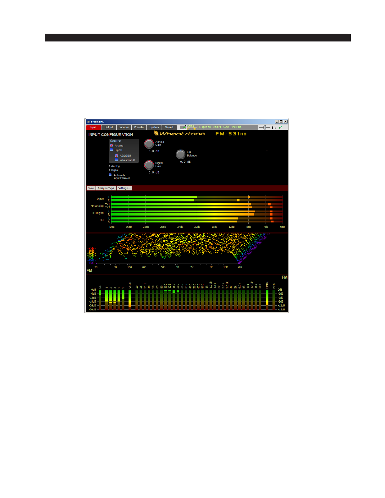
FM-531HD GURU GUI
Using Guru GUI
The GUI may be repositioned on the host computer’s screen by left‑clicking and
holding its title bar and dragging the GUI to the desired position. The GUI may also
be minimized on the desktop (taken off the screen) and/or closed by way of the familiar Windows controls at the extreme top right. Guru GUI may also be resized on
the desktop as desired by dragging its borders.
Descriptions of the features and functions of the GUI will follow the following
logical path:
- It will begin with the Control Area at the top;
‑ Followed by the Input/output Level displays;
‑ Followed by the Gain Reduction Displays;
‑ Ending with the Dynamic Analysis displays.
FM-531HD / May 2013
page 2 – 8
Page 42
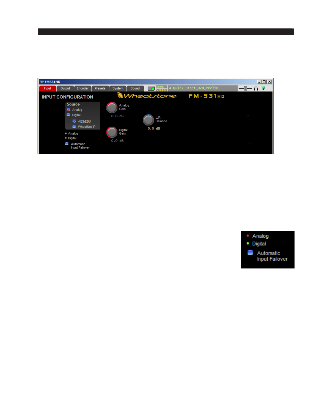
FM-531HD GURU GUI
Input Menu
This is the rst tab on the top far left of the GUI, noting that the screen that is cur-
rently being displayed is indicated by a red background on the selected tab.
The Input Conguration screen shown above contains controls for the Input Audio
Source, Automatic Input Failover, Analog Gain and Digital Gain, and L/R Balance
controls.
Input Source
The Input Source can be selected as either Analog, which is the analog Left/Right
input, or Digital, which can be either AES3 or WheatNet-IP. The currently selected
input choice is shown by a red check mark inside the blue choice box.
Audio Input Signal Presence Indicators
Below the source selection check boxes are a pair of signal presence
indicators for each input. The Analog indicator lights if there is a signal
present and the analog input exceeds ‑48dBFS. The Digital indicator
lights if there is a valid AES signal present at the digital input above
‑48dBFS. In this example, Digital is the active input (green indicator).
Automatic Input Failover
In the event the currently selected input source fails and the Automatic Input Failover
check box is checked, an alternate source of audio connected to the other input can
automatically be put on the air.
If the primary source was Digital the Analog input will be selected immediately if
invalid bits occur in the digital bitstream or after 30 seconds with an audio signal level
below ‑48dBFS.
If the primary source was Analog, then a timeout of 30 seconds must elapse before
the unit switches to the AES/EBU input in an attempt to restore audio. The audio failure
sense threshold is xed at ‑48dBFS, and this in combination with the 30 second timeout,
is suitable for virtually all program types.
Automatic Failover is between Analog and Digital sources only – failover between digital input sources (AES3 and WheatNet-IP) is not supported.
FM-531HD / May 2013
page 2 – 9
Page 43
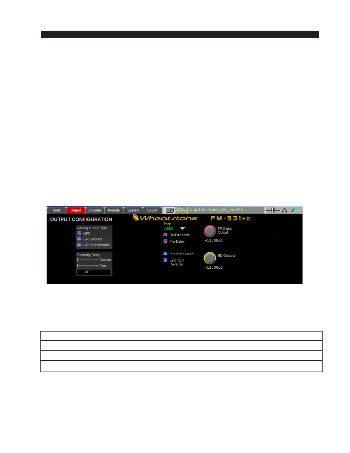
FM-531HD GURU GUI
Analog Gain
The Analog audio input gain may be adjusted by clicking on the Analog Gain knob
and dragging the mouse or touchpad to the right or left. The Analog Gain can be adjusted
over a range of +12dB to ‑36dB.
Digital Gain
The AES/EBU Digital audio input gain can be adjusted by clicking on the Digital
Gain knob and dragging the mouse or touchpad to the right or left. The AES Gain can be
adjusted over a range of +12dB to ‑36dB.
L/R Balance
Static level errors in Left/Right channel balance can be corrected by using the
L/R Balance knob and may be adjusted over a +/‑ 12dB range. The L/R Balance control
is common to both the analog and AES/EBU digital inputs.
Output Menu
This is the second tab from the left on the top of the GUI. (Note: the screen that is
currently being displayed is indicated by a red background on the selection tab).
The Output Conguration screen contains controls for selecting the Analog Output
Type, setting the FM Diversity Delay time, and for setting the FM Digital Output and
HD Outputs levels.
For best resolution of the Diversity Delay controls they are best adjusted using the
host PC’s keyboard and mouse and using the following table as a guide.
COARSE ADJUST SLIDER FINE ADJUST SLIDER
Slider only 500 mS Slider only 0.9 mS
Slider plus Shift key 1700 mS Slider plus Shift key 8.6 mS
Slider plus Ctrl key 50 mS Slider plus Ctrl key 0.1 mS (100µSec)
Note that the smallest increment of delay time adjustment is 100 microseconds.
FM‑531HD is also equipped with our Wheatstone® baseband192 digital composite
interface which provides a direct, pure digital signal path between the components of the
stereo multiplex spectrum and the associated transmitter’s digital FM modulator. With this
interface the usual A to D and D to A and/or sample rate conversions are absent resulting
in virtually perfect stereo baseband and modulation performance.
FM-531HD / May 2013
page 2 – 10
Page 44
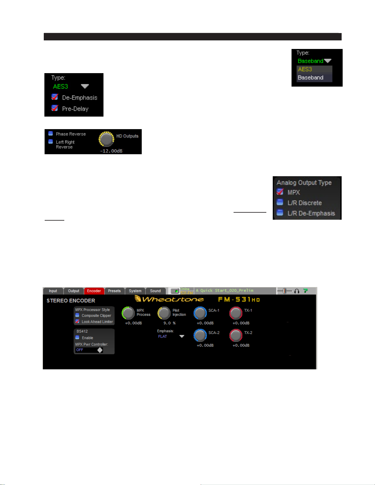
FM-531HD GURU GUI
The FM Digital output available as AES3 digital signal or baseband192
digital multiplex signal.
The FM AES3 Digital output offers options for applying
De‑Emphasis that is complimentary to Pre‑emphasis
that may be in use and also allows the digital output to
be taken before or after the FM Diversity Delay. To select the type
of pre‑emphasis, please see the ENCODER section below. Besides
de‑emphasizing the output, the signal can be routed pre or post the
FM diversity delay.
The HD Output has options for reversing the phase of
the left and right signals as well as for swapping the left
and right channels.
NOTE: The Analog Output Type box needs special mention!
Unlike other audio processors FM-531HD’s balanced analog
outputs can also carry balanced composite stereo. When the MPX
check box is selected, the rear panel TX-1 and TX-2 BNC connectors
are carrying the standard unbalanced composite stereo signal – at the
same time the XLR outputs are carrying balanced, line level composite
stereo. This feature has distinct advantages when the ultimate signal
to noise ratio is desired and the exciter being fed has a differential
input stage (most, if not all modern exciters do).
When the L/R Discrete or L/R De-Emphasis check boxes are checked an FM Analog
Output level control will appear in this screen and the TX level controls in the Encoder
screen will vanish.
Stereo Encoder Menu
The FM‑531HD contains a mathematically perfect stereo encoder whose performance
is limited only by the high speed output Digital to Analog converter (DAC) and its recon‑
struction lter. Stereo separation is typically >60dB between 20Hz and 15kHz. Clicking
on the Encoder tab opens the Stereo Encoder screen hosting controls for this section.
MPX Processor Style
The FM‑531HD provides two methods to process the composite stereo waveform.
These two methods are provided to allow the user to select what is most appropriate for
his format and market.
FM-531HD / May 2013
page 2 – 11
Page 45
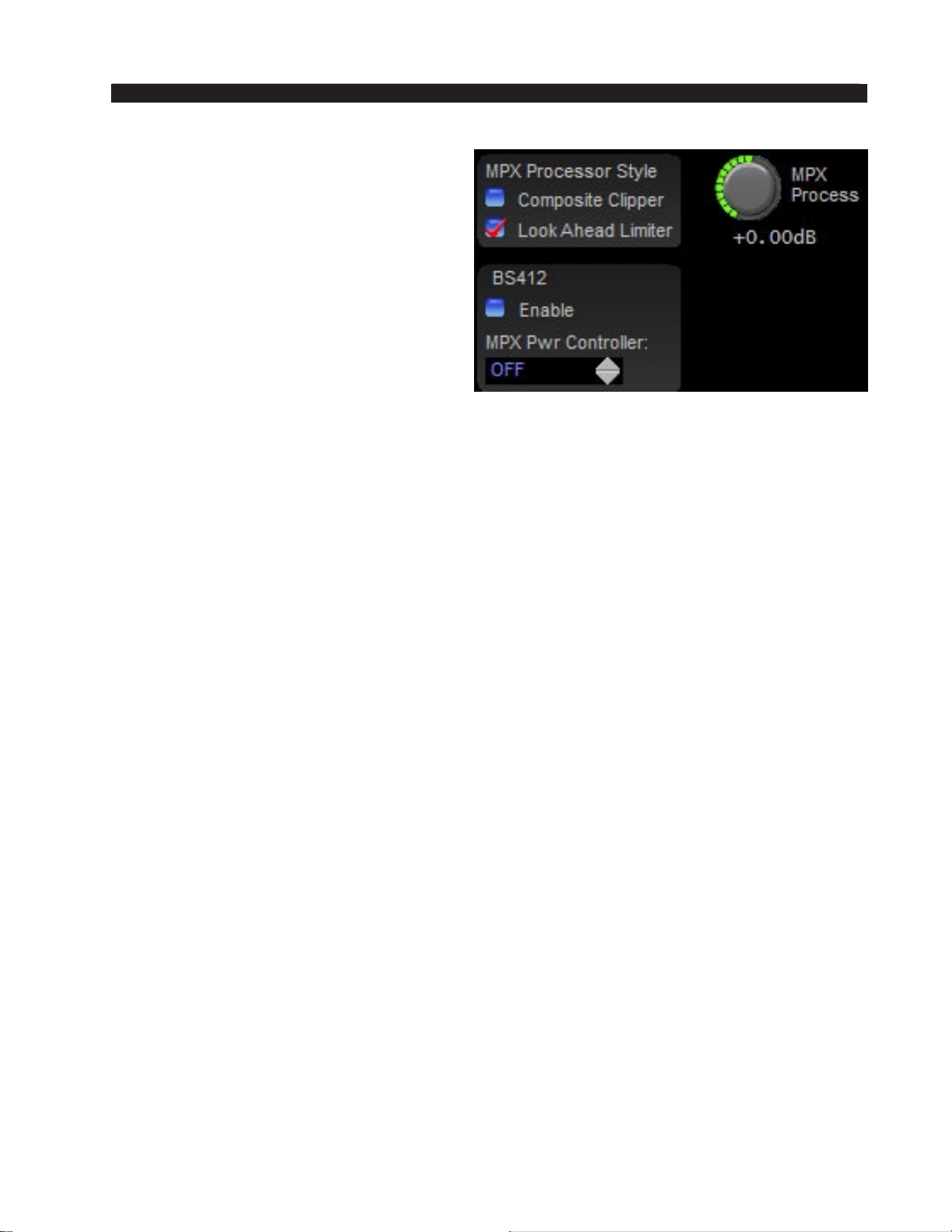
FM-531HD GURU GUI
Composite Clipper – Emulates analog
composite clippers but uses a very high
sample rate and special algorithms to drasti‑
cally reduce the artifacts caused by analog
composite clippers.
Look Ahead Limiter – This is a true
look ahead limiter which utilizes a 0.5 mil‑
lisecond look ahead and extremely high
sample rates to precisely control composite
waveform peaks on a cycle by cycle basis.
It works similarly to the oversampled look
ahead peak limiters found in the FM and
HD Limiter screens, but because of the
much higher bandwidth required by the composite signal, it operates at a much higher
sample rate.
MPX Process Control
The amount of MPX processing being applied to the composite signal is controlled
by the MPX Process control. This control is calibrated in 0.05dB steps and allows the
amount of MPX processing to be precisely set. Unlike other processors the control
may be set to values below 0dB for test purposes. Note also that unlike conventional
composite processors the amount of multiplex signal processing can be set quite ag‑
gressively without encountering the usual artifacts.
BS412 MPX Power Controller
In certain European countries the control of maximum Multiplex Power is required
by broadcast regulatory agencies. The regulation governing this is commonly referred
to as ITU‑R BS.412‑7, and the primary aim of controlling maximum MPX power is
to reduce adjacent channel interference by lowering the average modulation level.
FM‑531HD is equipped with a sophisticated MPX Power Controller which enables
it to operate within these regulatory guidelines. On the left side of the Stereo Encoder
screen are the two controls associated with its BS412 MPX Power Controller.
Note that the MPX Power Controller is always measuring multiplex power, even if
the Enable check box is not checked. Therefore if the MPX Power Controller setting
is set to any value except off, when the Enable check box is checked MPX Power will
immediately fall to the value set by the MPX Power Controller control.
Enable – When the Enable check box is checked the BS412 algorithm is control‑
ling the multiplex power. Likewise, when the check box is not checked, multiplex
power is not being controlled, regardless of the setting of the MPX Power Controller
control. As mentioned previously, when the Enable check box is checked the MPX
Power Controller will immediately set the processing output’s MPX Power to the
level set by the MPX Power Controller’s value.
MPX Power Controller – This control sets the maximum permitted multiplex
power according to the BS.412 measurement algorithm. The control has 15 possible
settings, plus an OFF position: +8db, +7dB, +6db, +5dB, +4dB, +3dB, +2dB, +1.5dB,
+1.0dB, +0.5dB, 0, ‑0.5dB, ‑1.0dB, ‑1.5dB, and ‑2.0dB.
FM-531HD / May 2013
page 2 – 12
Page 46
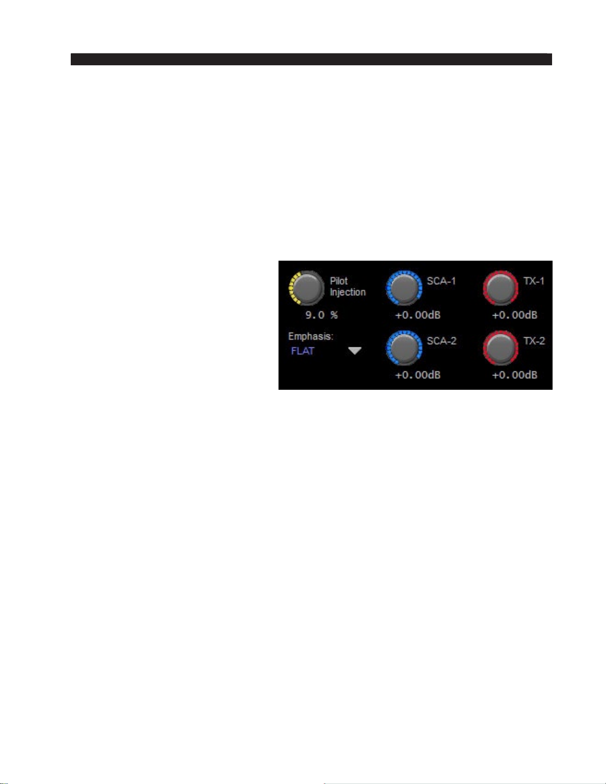
FM-531HD GURU GUI
There is a 0.5dB resolution available around the control’s zero setting to allow small
adjustments in actual MPX Power to compensate for unusual processing settings and how
they affect MPX Power.
IMPORTANT!
The MPX Power Controller’s sole purpose is to reduce loudness and program density.
If you are not required to use the BS412 Controller it should be left in the OFF position
because turning it on can cause up to a 5dB loudness loss when the control is set to its
“0dB” position. If your station is not required to comply with a Multiplex Power standard
where it is licensed to operate the BS412 control should remain in its OFF position!
Pilot Injection
The Pilot Injection control adjusts
the 19kHz stereo pilot level and is
adjustable from 0 (Off, to cause the
station transmit in Mono) to 20% of
the main composite signal amplitude,
in 0.1% steps.
Emphasis
This control sets the desired pre‑
emphasis curve to apply, 50 or 75 mi‑
croseconds, depending on the part of
the world where the FM‑531HD is being used. The pre‑emphasis may also be switched
off (FLAT) for testing or other purposes.
SCA-1 and SCA-2 Inputs
Input signals such as SCA and RDS applied to the SCA connectors are digitized
at 192kHz. Prior to being digitized the signals are high pass ltered to reduce hum
and then low-pass ltered at 94kHz. This control can be set to OFF or to levels from
‑79.95dB to +10.0dB in 0.05dB steps.
TX-1 and TX-2 Outputs
These controls adjust the output amplitude of the signals appearing at the rear
panel BNC and XLR connectors when the Output Mode is set to MPX in the Output
Conguration screen. The TX‑1 and TX‑2 controls also adjust the modulation levels
of the Baseband192 output. Currently only the TX‑1 signal is supported by transmit‑
ter manufacturers.
These controls can be set from ‑79.95dB to +6.00dB in 0.05dB steps. Note that the
audio levels at the balanced XLR connectors are always 6dB higher than the levels at
the unbalanced BNC connectors.
FM-531HD / May 2013
page 2 – 13
Page 47
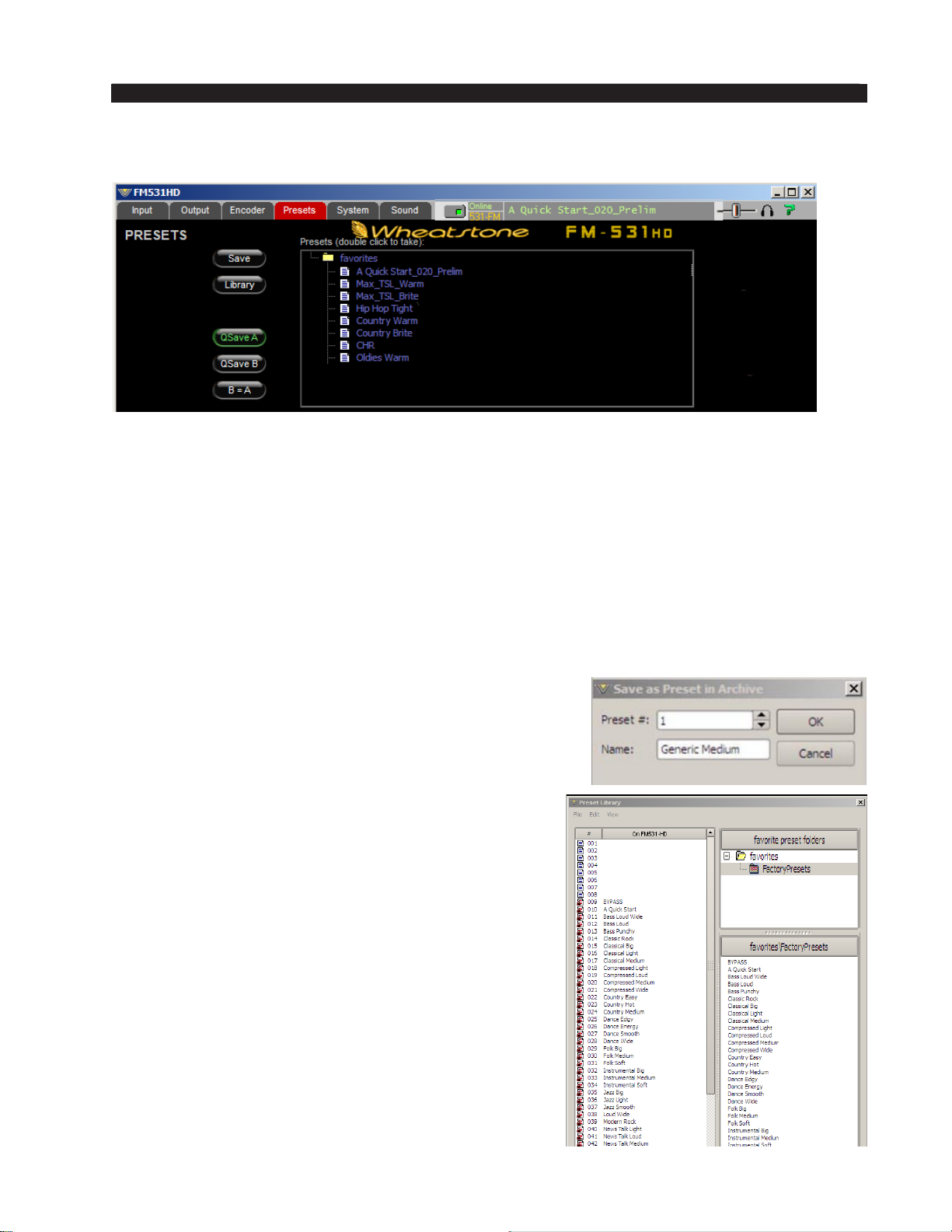
FM-531HD GURU GUI
Presets Menu
The Presets tab opens a screen where presets may be selected for on air, saved to the
processor, or managed through the FM‑531HD’s comprehensive Preset Library Manage-
ment utility.
Selecting a Preset
Selecting a preset for on-air use is as simple as double-clicking on a preset in the
list. The currently running preset will morph into the new preset over a period of several
seconds in order to prevent abrupt clicks and pops when the new preset’s parameters are
being loaded.
Saving a Preset
When the Save button is pressed a dialog opens allow-
ing a preset name to be entered.
Once the entered preset name is satisfactory, press the
Save button to commit it to memory, noting that unless
chosen otherwise it will be stored in the FM‑531HD’s next
available open preset slot.
Preset Library Functions
Clicking on the Library button opens up the preset
library management feature. When this window is open
both the presets on the FM‑531HD hardware itself (on
the left side of the window) and on the host PC (right
side of the window) are visible.
To move presets from the hardware to the PC or
vice versa, simply drag the preset in the direction you
wish it to go. Whenever presets are being moved from
the FM‑531HD to the PC, a copy of the preset being
dragged over will remain in the Library window.
The same goes for the behavior when dragging a
preset from the PC to the hardware – a copy of the preset
is sent to the hardware – the original preset remains on
the PC for safekeeping.
FM-531HD / May 2013
page 2 – 14
Page 48
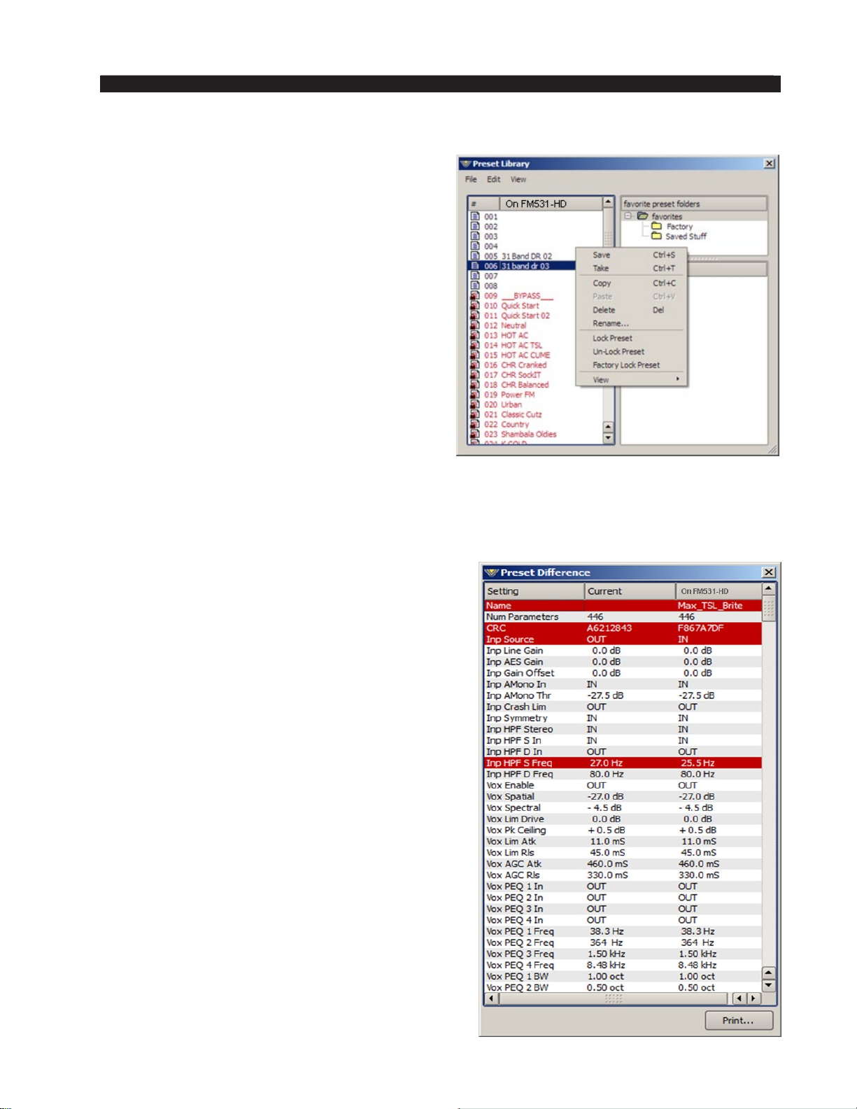
FM-531HD GURU GUI
Locking Presets
Presets stored on the FM‑531HD may
be locked by the user to prevent inadvertent
overwriting, renaming, or deletion. This is
accomplished by opening the Preset Library
by clicking on the Library button in the GUI.
Once the list of presets is open, the ones actually stored within the processor hardware itself
will be visible in the left pane.
There are two ways to manage the lock status
of user presets:
• The rst method is by highlighting a preset
(single left click) and then right clicking it
to open a dialog box. Among the options
are Lock Preset and Unlock Preset.
• The second method is by highlighting a
preset as above, and then clicking the Edit
option at the top of the Preset Library
dialog box to reveal the Lock Preset/Unlock Preset options. Note that these are
user-level lock options and therefore cannot be used to override the lock status of
a factory-locked preset!
How to View Preset Changes
It is possible to visually compare two different
presets on the FM‑531HD with a special feature
called Preset Difference.
When the Library tab is opened, highlight any
preset you’d like to compare with the current pre-
set running on the processor. Then right click and
select View and Diff from the sub-menu. You will
see the window on the right open.
Any parameter that is listed with a RED background indicates a parameter that is different between the preset running on the hardware and the
preset that has been highlighted. Parameters which
are not highlighted have the same values between
the two presets.
FM-531HD / May 2013
page 2 – 15
Page 49
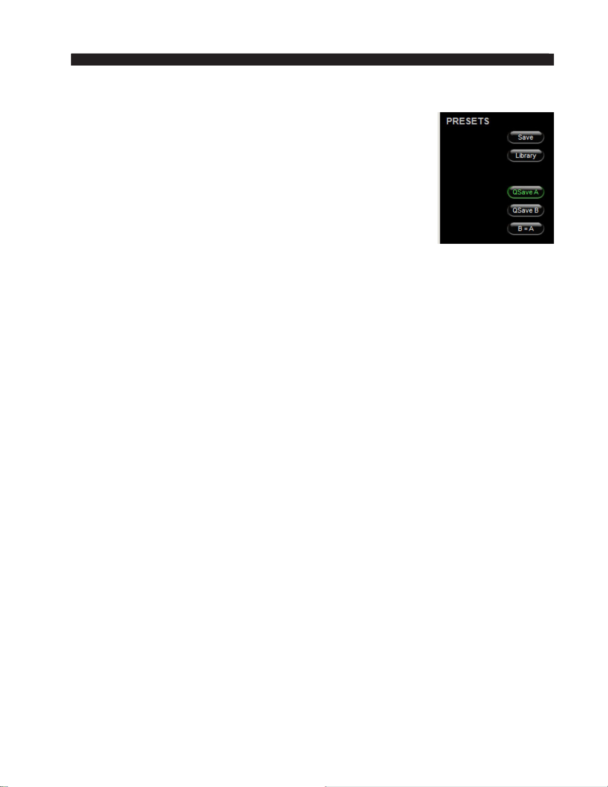
FM-531HD GURU GUI
Quick Save (QSave)
The FM‑531HD has a unique feature that allows instant comparison
of work in progress to a known reference, such as another preset, or
some midpoint while adjustments are being made. We call this feature
QSave (for Quick Save).
At the left side of the Presets menu you’ll nd three buttons like
those shown on the right.
QSave A and QSave B represent two temporary memory buffers
that hold all current FM‑531HD processing settings as long as power
is applied to the unit.
While QSave A is highlighted green any adjustments that you
make to controls on the FM‑531HD are being concurrently saved to
temporary buffer A.
QSave B operates on buffer B and just like QSave A its being selected is shown by
a green highlighting.
One way to use this feature is to compare the sound of a factory preset to changes
you’ve made to it without having to rst save it as a user preset. To do this:
• Recall the factory or user preset that you wish to adjust.
• Ensure that QSave A is highlighted. If it is not, press its button to highlight it.
• Press the B=A button. This will copy the contents of QSave buffer A to QSave
buffer B. Now the contents of both A and B buffers are identical.
• Change some settings on the FM‑531HD and they will automatically be stored in
the A buffer.
• Compare your changed settings to the recalled factory preset by pressing the QSave
B button.
• Compare those settings back to the factory preset by pressing QSave A.
• When you are happy with your changes you can commit them to a user preset using the preset Save dialog explained previously.
Likewise, QSave A and QSave B can be used to compare the sounds of two different
sets of user settings. To do this:
• Load the preset that you want to change, make changes to it, and press QSave A
to save those settings to buffer A.
• Make some additional changes and then press QSave B to save those additional
changes to buffer B.
• Now buffers A and B have your two different settings. You can compare them by
toggling back and forth between QSave A and QSave B.
• When you are pleased with one set of settings and need more buffers for further
tweaking, you can use the A=B/B=A button to make the two buffers the same and
have one of them to use to start comparing from again.
FM-531HD / May 2013
page 2 – 16
Page 50
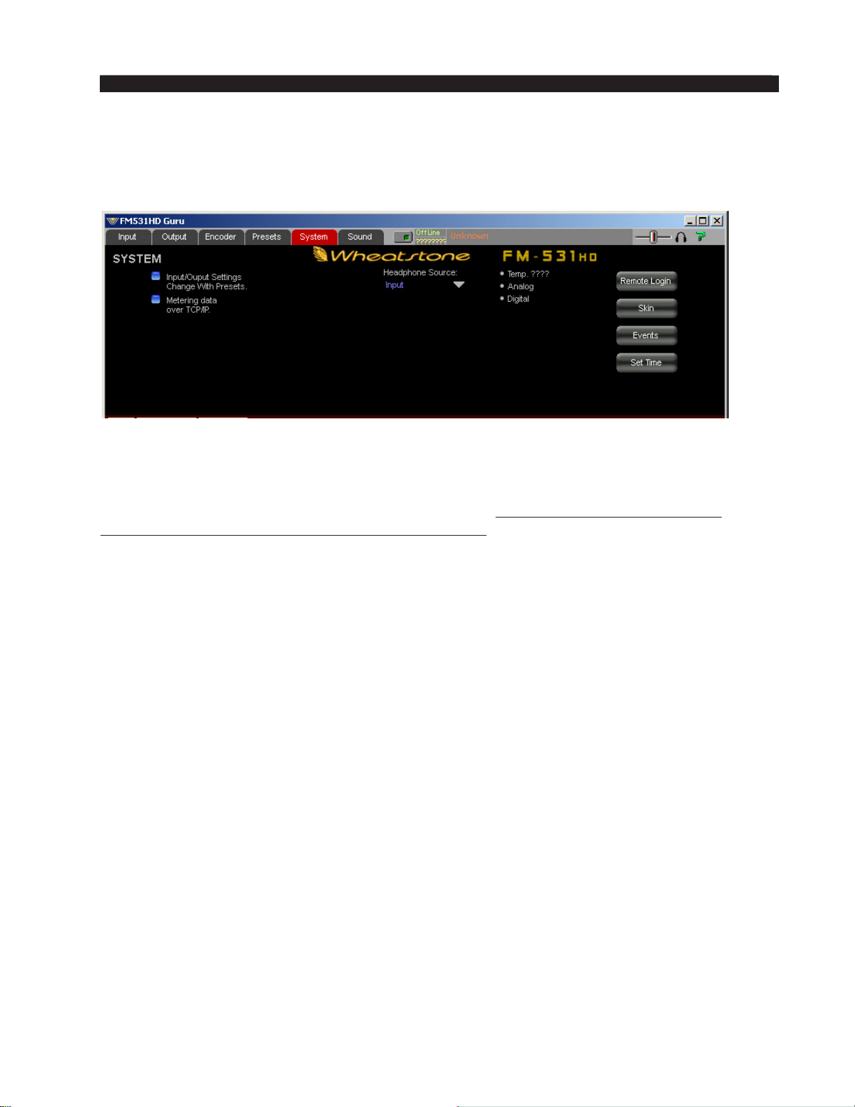
FM-531HD GURU GUI
System Menu
The System screen allows system‑wide settings to be congured. The following
features and options are available within the System menu.
Input/Output Settings Change With Presets
Wheatstone processors segregate “sound” settings like AGC Drive from “system” settings like Analog Output Level. However, unlike other processors you may
be familiar with, when a Wheatstone preset is saved all currently active parameters
are stored with that preset, including system settings. This is an advantage when one
wants to change one or more system settings without changing the sound, or change
one or more system settings and change the sound.
This means that processing presets can be used to adjust system parameters whenever
desired. An example of how this feature could be used is where a station is transmitting a mono sports broadcast and doesn’t want to change the sound but does want the
stereo pilot off while the broadcast is in mono.
When the check box labeled Input/Output Settings Change With Preset is checked,
all of the system settings stored within a preset will be applied when that preset is
taken. In the above example two presets saved as identical other than the stereo pilot
setting could be used to turn the stereo pilot on and off without changing anything
else. If these presets are stored in the rst eight preset slots then GPI signals applied
to the FM‑531HD rear panel can select these presets with remote contact closures.
Metering Data via TCP/IP
As mentioned previously, sometimes UDP packets are blocked by an Internet
provider or in house router, rendering the GUI without metering (because it uses the
UDP protocol for that). In this situation metering can be restored simply by selecting
the Metering data over TCP/IP check box.
The downside of operating the GUI in this mode is that, unlike UDP, which requires
(and expects) no handshaking to guarantee data integrity, TCP/IP requires handshaking
on every packet to ensure that each packet received is identical to the one transmitted.
On a noisy or poor link, the need to handshake on every metering packet can slow the
network down because of the additional handshaking and data transmissions required.
FM-531HD / May 2013
page 2 – 17
Page 51
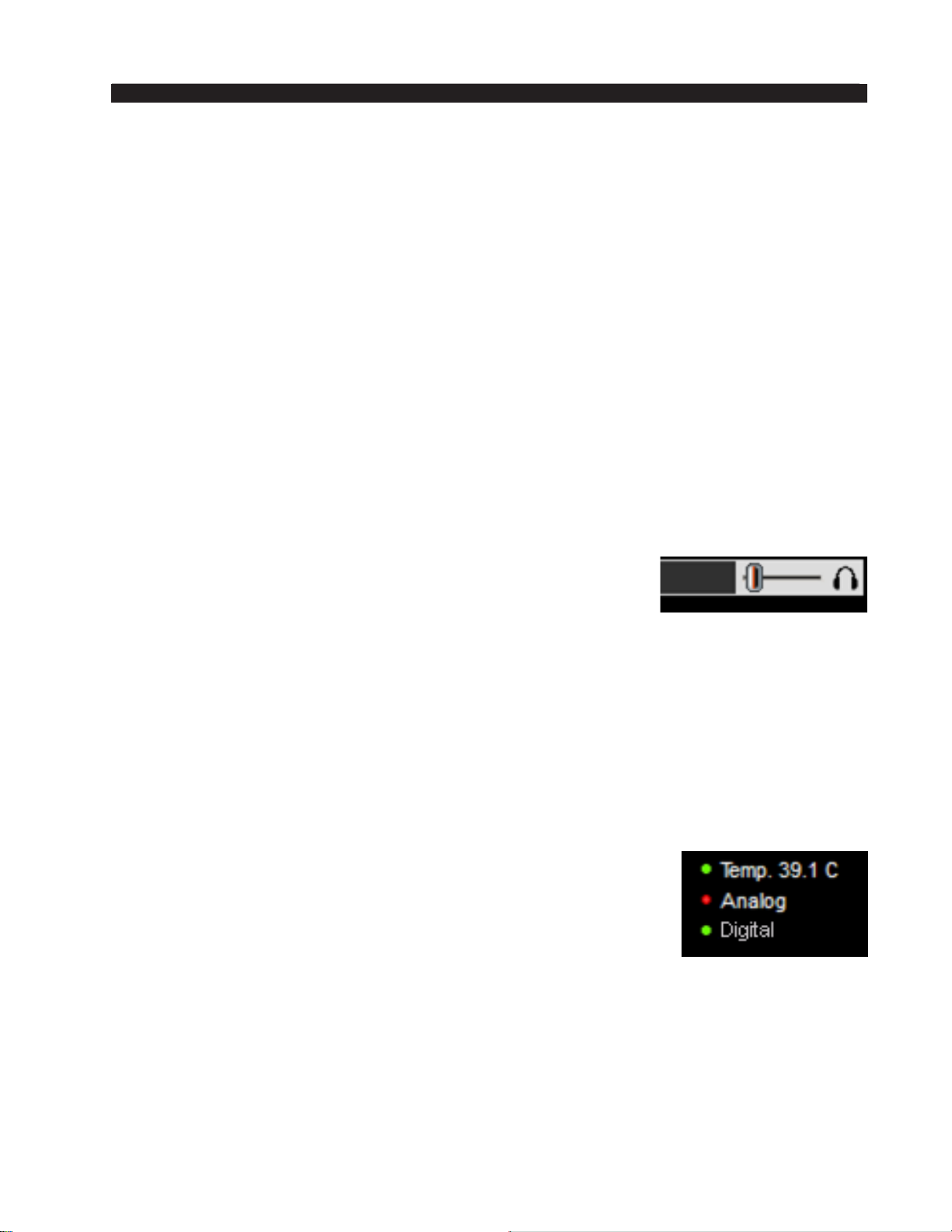
FM-531HD GURU GUI
Headphone Source
The headphone source may be directed to several points inside the processing chain:
• Input: Output of the audio input selector, whether analog or AES input is selected.
• Analog Input: Audio appearing on the analog input even if not selected to be
on air.
• AES Input: Audio appearing on the AES3 digital input even if not selected to
be on air.
• HD Output: Output of the entire HD processing chain.
• FM Output: Listens to the output of the entire FM processing chain, including
the FM diversity delay. Note that if pre‑emphasis is on, this signal will be bright
because it is pre‑emphasized.
NOTE: The FM‑531HD’s headphone monitoring feature allows monitoring of an au-
dio input without having to put it on the air. This is useful for conrming that backup
audio is actually present and acceptable before putting it on the air!
Headphone Volume Control
On the top right corner of Guru GUI is the headphone volume
control slider. To adjust the headphone volume slide the fader right
to increase volume and left to decrease it.
Note: The headphone outputs of the FM-531HD are driven
by National Semiconductor LM675 power operational ampliers capable of >3A
into any reasonable load. Actual headphone impedance is not a concern; how-
ever headphone circuit current limiting is provided at 160mA in order to protect
external devices and also to keep you from setting your hair on re from too high
a headphone listening level!
Status Indicators
There are three status indicators: Temp, Analog, and Digital.
Temp
This indicator is green when the GUI is online to the FM‑531HD
and its internal temperature is below 50°C/122°F. The numbers dis-
played represent the current temperature of the hardware.
Analog
This indicator is green whenever there is analog audio present on
both left and right channels and it is above ‑24dBu.
Digital
This indicator is green whenever there is a valid AES3 digital audio signal present
and it is above ‑48dBFS.
FM-531HD / May 2013
page 2 – 18
Page 52
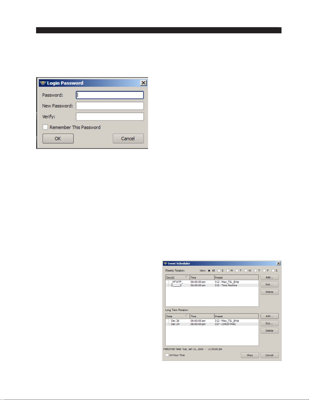
FM-531HD GURU GUI
Remote Login
When Remote Login is clicked, a Login Password prompt box will open as shown
below:
A remote login password restricts GUI
access to an FM‑531HD processor over
the Ethernet connection. When a remote
GUI session is initiated, the FM‑531HD
accepts the connection and asks the remote
GUI for a password.
If the remote GUI can’t provide the
password, a dialog box pops up asking
for the correct password. Until the login
password can be veried the FM‑531HD
will not send its current settings to the
remote GUI nor accept any changes from
the connecting GUI.
This dialog box allows you to change the login password. You need to know the
current password beforehand (if one has already been assigned), and also enter the new
password twice for verication. The password can be any combination of characters
or numbers.
If the Remember This Password check box in the dialog is checked, the GUI stores
the password on the local PC. If you do not check the check box you will be asked
for the password each time you connect remotely (since the rst round of verication
will fail due to no locally stored password).
Occasionally you may see the word “pending” temporarily appear in the connection
status box of the remote GUI while the FM‑531HD and Remote GUI are handshaking
on the password string being sent.
Events
The FM‑531HD contains a comprehensive
scheduling utility that allows presets to be au‑
tomatically changed on desired dates and times.
There is also a Long Term Rotation scheduler
that allows preset changes to be scheduled for
any time in the future. To create, edit, or view
entries in the Event Scheduler click the Events
button on the System Screen.
The Event Scheduler screen shown on the
right will open and the events list will be empty
when opened for the rst time:
Creating a Weekly Rotation Schedule
1. Click the Add button in the Weekly Rotation area of the Event Scheduler window.
FM-531HD / May 2013
page 2 – 19
Page 53
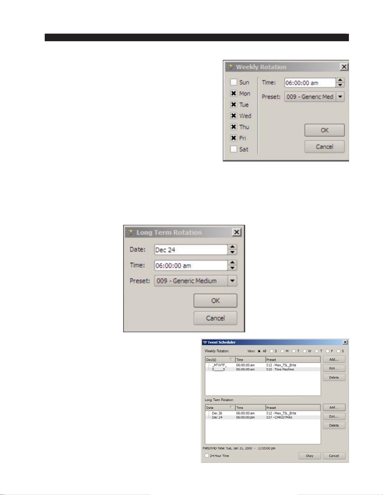
FM-531HD GURU GUI
The Weekly Rotation window will open as shown
on the right.
2. On the left column, select the days that the preset
should be selected. Any combination of check
boxes may be chosen.
3. Next select the time that the preset should change.
4. Next choose the preset that should be selected
at the time programmed in the previous step.
When nished editing, click OK.
As many preset change events as desired may be
programmed in the Event Scheduler.
If a one‑time preset change is required, such as might be necessary for a special holiday
or other event, the Long Term Rotation routine should be used.
Creating a Long Term Rotation Schedule
Adding a new event in the Long Term Rotation scheduler works in a similar manner.
The Long Term Rotation entry window appears as follows:
Deleting a Scheduled Event
Deleting a scheduled preset change is as
simple as adding one. Open the Event Scheduler
window by navigating to the System menu and
clicking Events. The Event Scheduler window
will open.
To delete an item in either the Weekly Rota-
tion or Long Term Rotation schedules simply
highlight it in the list and then click the ap‑
propriate Delete button on the right side of
the Event Scheduler window. The highlighted
scheduled event will be removed from the list.
Note that there is no conrmation prior
to the actual deletion of the event!
FM-531HD / May 2013
page 2 – 20
Page 54
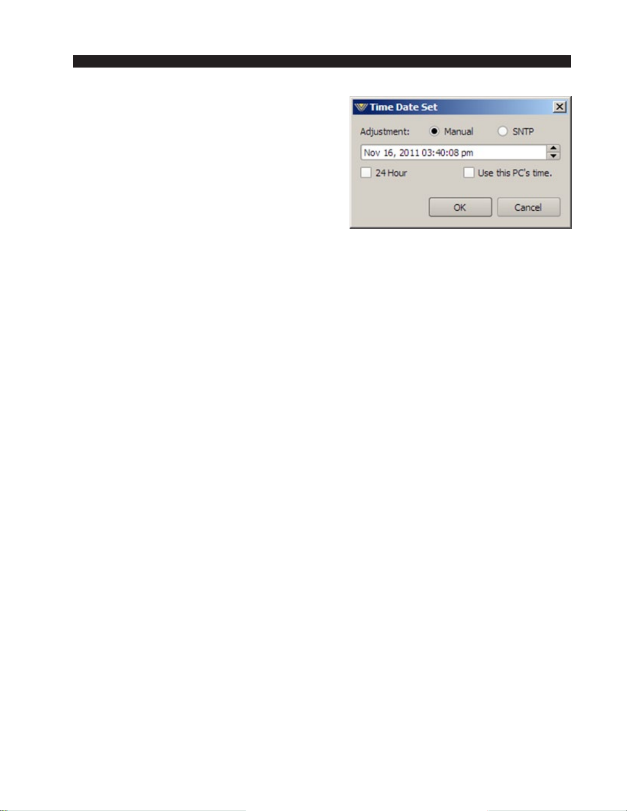
FM-531HD GURU GUI
Setting System Time
Allows the system time of the FM‑531HD’s
onboard computer to be set or changed.
FM‑531HD’s system time can be synchronized to
external time servers (SNTP, or Simple Network
Time Protocol) if desired. Alternately, time can
be synchronized to the PC that is running the
Windows-based GUI. In this instance time updates
will occur upon successful connection to the GUI
on the remote PC.
SNTP (Simple Network Time Protocol)
The FM‑531HD supports automatic and unattended system time updates via SNTP.
Using SNTP can keep the FM‑531HD’s onboard clock set to within milliseconds of actual
time. Various “time servers” are available via an internet connection and a partial list of
available time servers is below. All servers shown are located within the United States.
IP Address Name Location
129.6.15.28 time‑a.nist.gov Maryland
129.6.15.29 time‑b.nist.gov Maryland
132.163.4.101 time‑a.timefreq.bldrdoc.gov Colorado
132.163.4.102 time‑b.timefreq.bldrdoc.gov Colorado
132.163.4.103 time‑c.timefreq.bldrdoc.gov Colorado
128.138.140.44 utcnist.colorado.edu Colorado
192.43.244.18 time.nist.gov Colorado
131.107.1.10 time‑nw.nist.gov Washington (Microsoft)
69.25.96.13 nist1.symmetricom.com California
216.200.93.8 nist1‑dc.glassey.com Virginia
208.184.49.9 nist1‑ny.glassey.com New York
207.126.98.204 nist1‑sj.glassey.com California
207.200.81.113 nist1.aol‑ca.truetime.com California
68.216.79.113 nist1.columbiacountyga.gov Georgia
NOTE: If FM‑531HD’s NTP function is enabled the network that the FM‑531HD is
connected to must have a path for retrieving the correct time, whether it is from a local
NTP server at the station or one that is reachable over the Internet. The NTP time function cannot work if the FM‑531HD is not connected to a network, or is connected to a
network with no path to an NTP server.
FM-531HD / May 2013
page 2 – 21
Page 55
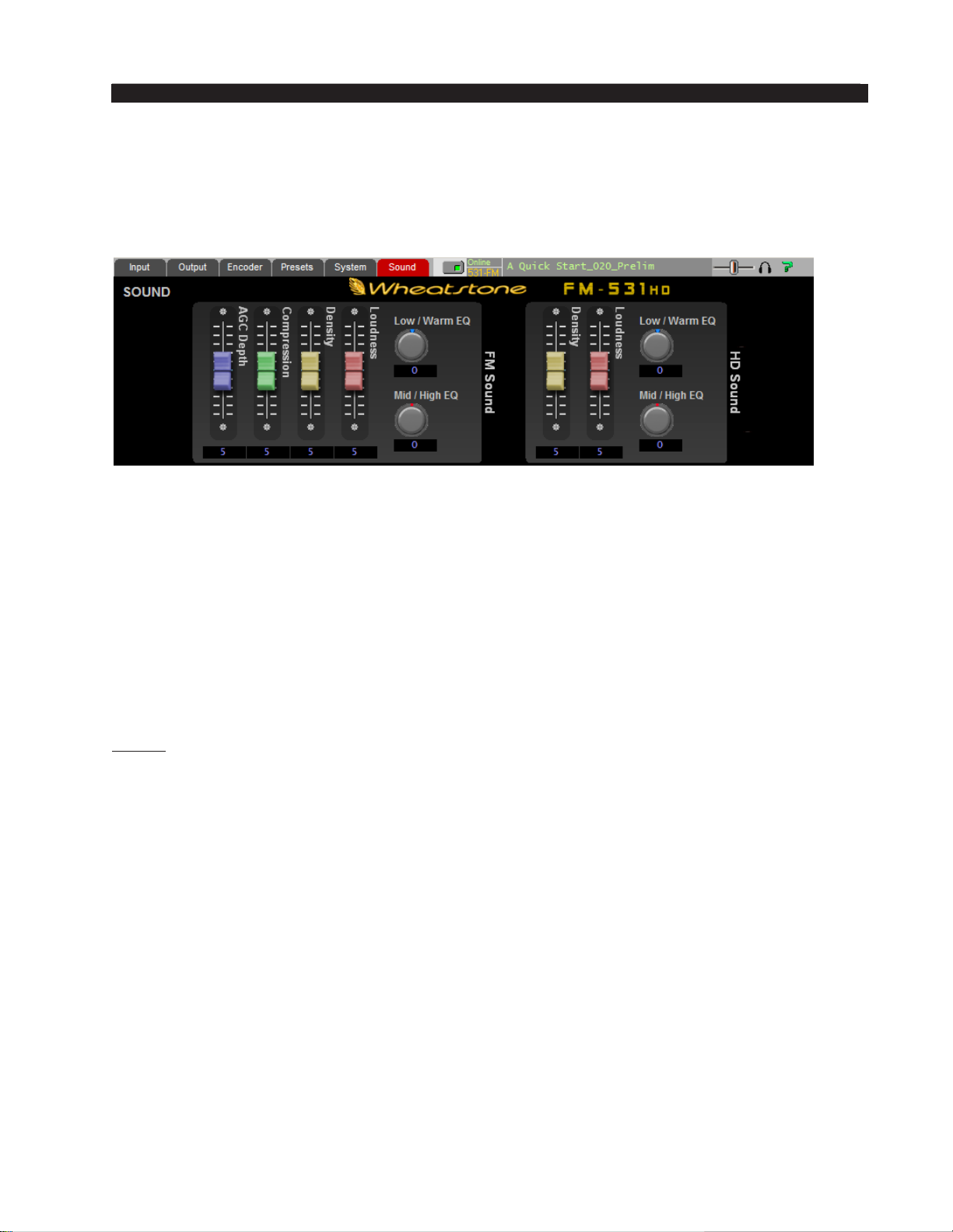
FM-531HD GURU GUI
Sound Menu
Selecting the Sound tab will reveal the ten controls of Guru GUI, six for FM and four
for HD. It is these simple to use but quite powerful controls that can morph the sound of
any Factory preset into over one million different sounds and textures.
There are two sections to the Sound screen. The left side contains the controls that
modify the sound of the FM signal path while the far right side hosts the controls for
adjusting the sound of the HD signal path. Note that the FM and HD signal paths share
the common ve band AGC/SST structure so as to maintain a consistent spectral texture
as an HD receiver blends from analog to HD. The AGC Depth and Compression sliders
are shared between the FM and HD signal paths.
Each sound slider is intelligently connected to myriad controls (over 425) that are
accessible via the full‑control “Expert” level Professional GUI. As each Sound slider is
adjusted to the eleven positions within its 0 to 10 range, many complementary adjust-
ments are occurring behind the scenes to modify the sound according to the naming and
purpose of the controls. The following is an explanation of what each FM Sound slider
control does, again keeping in mind that the AGC Depth and Compression slider are
shared between the FM and HD processing chains.
FM Sound Adjust
AGC Depth
The AGC Depth control adjusts how deep the AGC’s long term gain reduction will
be with typical program material and with appropriate input levels. Higher settings cause
deeper long‑term gain reduction and the additional “reserve” gain caused by raising the
setting of this control will tend to hold up fading songs longer. Conversely a lower set-
ting of the control causes gain reduction that is less deep, leaving less gain available to
hold up program levels of material (such as songs) as it fades.
Note that the AGC Depth slider does not modify the time constants within the
AGC/SST section. That is the job of the Compression slider, discussed next.
Compression
The Compression control adjusts the medium term program density and how obvious
the processing will sound. Lower settings cause the processing to be virtually inaudible
as it corrects levels and spectral balance as incoming program elements change. Adjust-
ing the slider to higher numbers makes the gain controlling action more audible. Higher
Compression settings also cause the audio to “ll up” and become more “full.”
FM-531HD / May 2013
page 2 – 22
Page 56
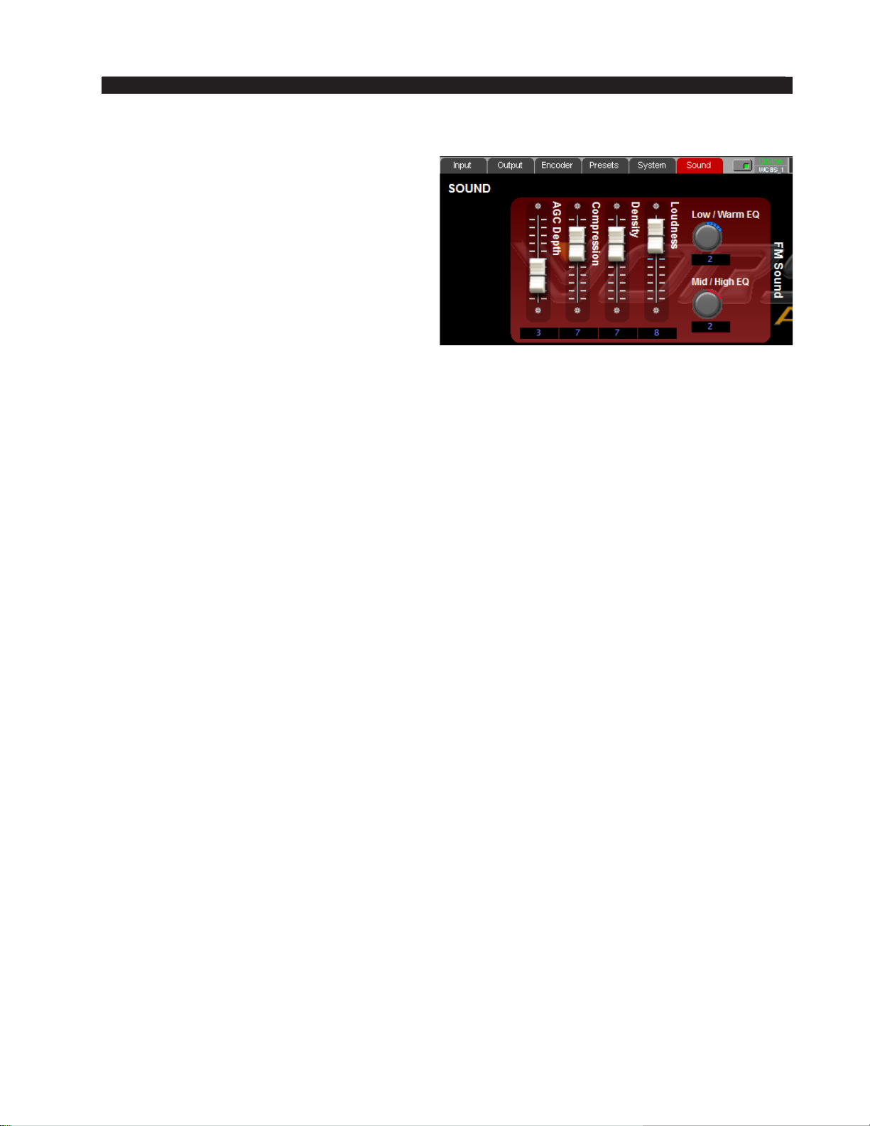
FM-531HD GURU GUI
Density
The Density control adjusts how much
short‑term limiting is permitted. Higher settings will make the audio more dense and
“processed” sounding while lower settings
will be less so. Stations looking for a “compressed” sound will nd the Compression and
Density controls quite useful for tailoring the
“feel” of their audio. Note that increasing
the Density setting will not cause the nal
clipper to be overdriven because Guru GUI’s
intelligence makes other adjustments behind
the scenes to prevent it. In other words, distortion will not increase simply because
Density was increased.
Low/Warm EQ (we’re leaving Loudness for last!)
The Low/Warm EQ control adjusts how powerful low frequencies sound on the
air. When the control is at “0” and has not been touched since a preset was last taken
the factory assigned equalization for that preset is being applied. Adjusting the control
either side of “0” increases or decreases the factory equalization settings. In general,
setting the control to lower numbers reduces on-air bass while moving it to higher
numbers increases it.
Mid/High EQ
The Mid/High EQ control adjusts how the higher frequencies sound on the air.
When the control is at “0” and has not been touched since a preset was last taken the
factory assigned equalization for that preset is being applied. Adjusting the control
either side of “0” increases or decreases the factory equalization settings. In general,
setting the control to lower numbers reduces on-air highs while moving it to higher
numbers increases them.
Loudness (finally!)
The Loudness slider is used to set the desired on‑air loudness. The most complex control within the entire Guru GUI structure, it intelligently communicates with three powerful sections of the FM‑531HD’s processing; the 31‑band limiter, the FM Limiter/Clipper and the MPX processing. Its intelligent hand on these other processing sections automatically optimizes the distortion vs. loudness tradeoffs as the Loudness
slider is adjusted.
FM-531HD / May 2013
page 2 – 23
Page 57
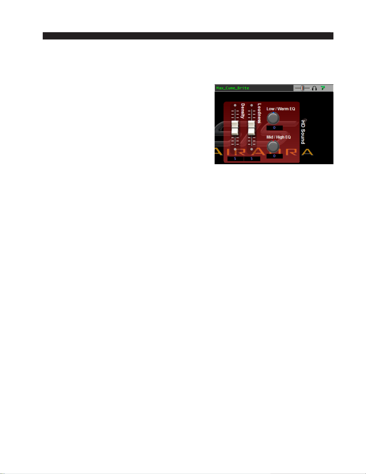
FM-531HD GURU GUI
HD Sound Adjust
Density
The HD Density control adjusts how much short-
term limiting is permitted within the multiband and
broadband limiting sections. Higher settings will make
the audio more dense and “processed” sounding while
lower settings will be less so. Stations looking for a
“compressed” sound on their HD signal will nd both
the Compression and Density controls quite useful for
tailoring the “feel” of their audio. Note that increasing
the Density setting will not cause the look ahead limiter to be overdriven because Guru GUI’s intelligence
will make other adjustments to prevent it. Distortion
and/or audible pumping will not increase simply be-
cause Density was increased.
Low/Warm EQ
The Low/Warm EQ control adjusts how powerful low frequencies sound on the
HD signal. When the control is at “0” and has not been touched since a preset was last
taken the factory assigned equalization for that preset is being applied. Adjusting the
control either side of “0” increases or decreases the factory equalization settings. In
general, setting the control to lower numbers reduces on‑air bass while moving it to
higher numbers increases it.
Mid/High EQ
The Mid/High EQ control adjusts how powerful the higher frequencies sound on
the HD signal. When the control is at “0” and has not been touched since a preset was
last taken the factory assigned equalization for that preset is being applied. Adjusting
the control either side of “0” increases or decreases the factory equalization settings.
In general, setting the control to lower numbers reduces on‑air highs while moving it
to higher numbers increases them.
Loudness
Once the previous controls have been adjusted for the desired sound texture, the
Loudness control can be used to set the desired HD loudness. The Loudness slider
intelligently communicates with the HD processing’s 31‑band limiter and its look
ahead limiter.
As the Loudness control is adjusted upwards of “5” the sound will get denser and
louder. The opposite occurs when the control is adjusted downwards of “5.”
Note that the Loudness control’s interaction with other processing sections has been
tuned to avoid undesired artifacts such as audible pumping and/or distortion when the
control is set to either extreme.
FM-531HD / May 2013
page 2 – 24
Page 58
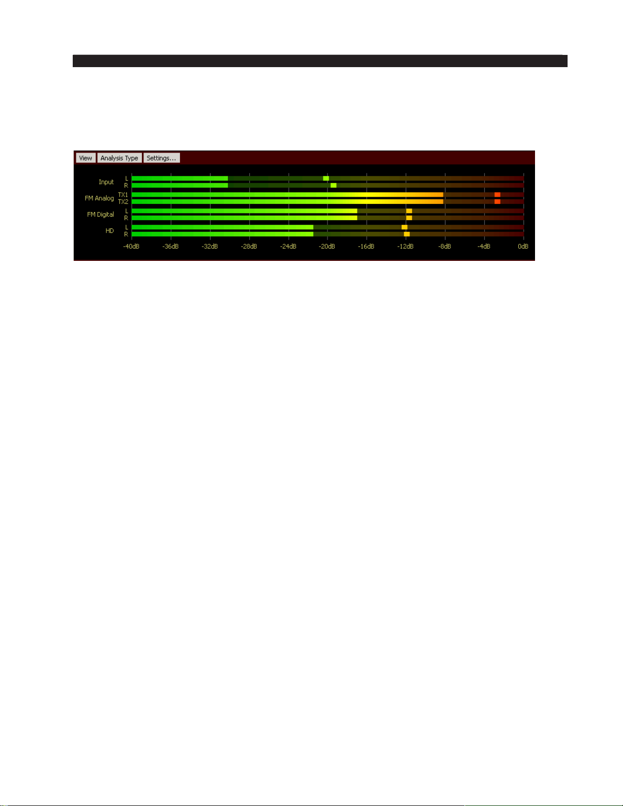
FM-531HD GURU GUI
Audio Input and Output Metering
The FM‑531HD provides high resolution level metering for all input and output
signals.
The topmost pair of horizontal bargraph meters show the applied input levels of
the selected audio source, after that source’s Gain control. Like many meters in the
FM‑531HD the input level meters are calibrated in dBFS, for decibels Full Scale. The
right hand “0dB” marking represents the absolute level where there are no more digital
bits left for dening the input signal – any signal above this will cause severe distortion. The left hand “‑40dB” marking represents the audio level that many of the silence
sense/audio failover circuits use for making their logic decisions.
So, what are normal input levels? Because we are working in the digital domain
great care must be taken to ensure that audio levels aren’t run so high as to cause them
to run out of headroom. Good engineering practice dictates that levels arriving from
the studio or STL should be peaking between ‑20dB and ‑12dB on the input meters and
no higher. This allows headroom for the occasional “hot” audio level.
Operating the Input meters at lower indications won’t bring up noise or other artifacts
that we might be familiar with in analog circuits. With FM‑531HD’s 144dB internal
dynamic range there is virtually no chance of increasing noise by running with “light”
audio input levels, though users would likely nd that they may need to increase the
setting of the AGC Drive control to compensate.
The FM‑531HD’s FM Analog, FM Digital and HD output levels are also shown
on the bargraph level meter display and their scales match that of the Input meter display. The big difference in the output meters is that because the output levels they are
displaying are “post processing” peak levels are not only known, they are very well
controlled. Therefore there is no need to leave headroom for output signals as we must
do for input signals.
FM-531HD / May 2013
page 2 – 25
Page 59
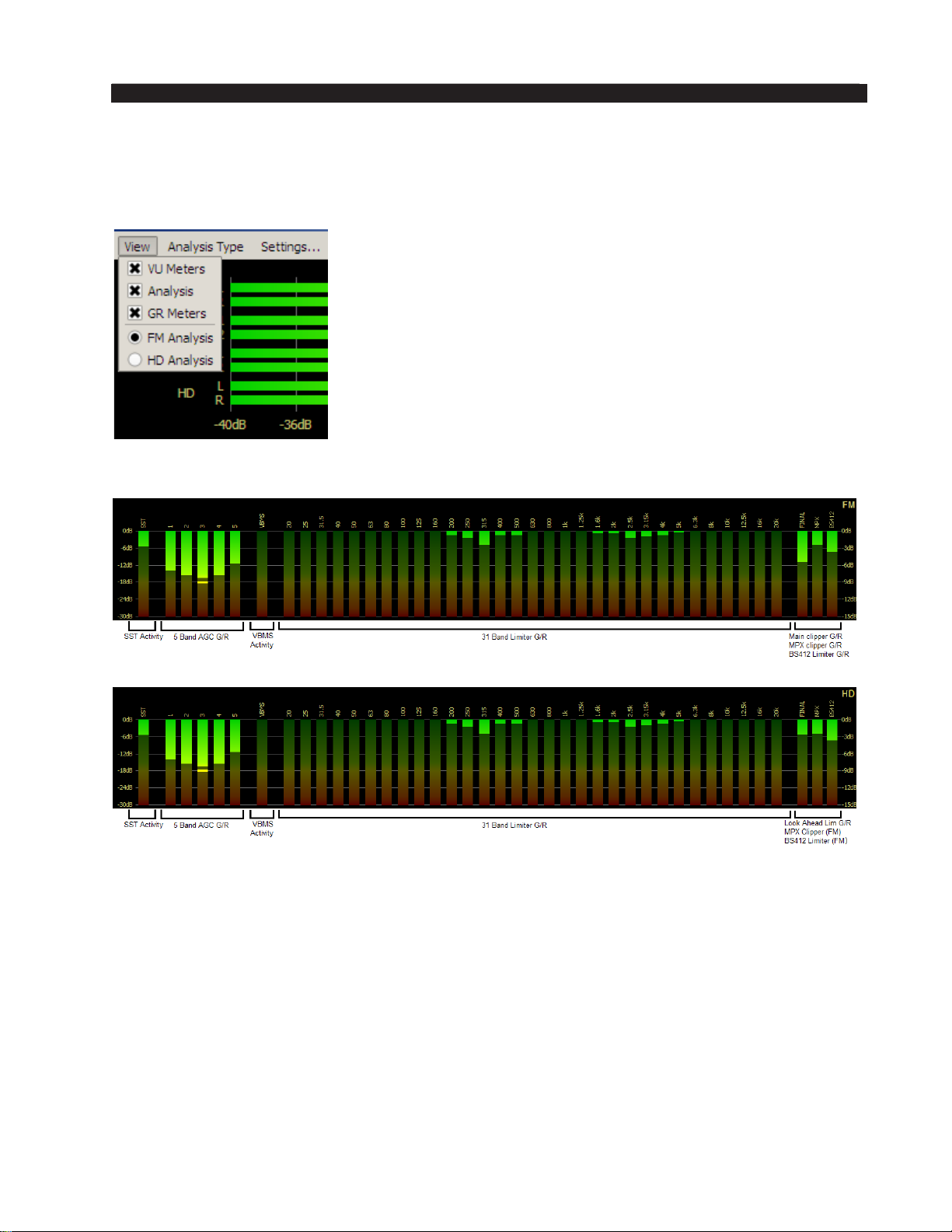
FM-531HD GURU GUI
Audio Processing Gain Reduction Displays
At the bottom of the GUI display are the vertical bars representing the amount of
activity occurring in each of the FM‑531HD’s processing sections.
The View button on the top-left of the metering section allows
you to scale the size of the GUI. This is done by “turning
off” some or all of the metering and analysis displays. The
check boxes allow you to pick the metering and analysis
you want to view.
Also, there is an option for which processing path you
want the analysis to display. The options are for the FM path
or the HD path.
FM Metering
HD Metering
The meters are arranged in seven logical groups as follows:
- SST Activity meter;
‑ Five‑band AGC gain reduction;
‑ VBMS Activity meter;
‑ 31‑band Limiter gain reduction activity;
‑ Final Limiter gain reduction or Clipper activity;
‑ MPX Limiter gain reduction or Clipper activity;
‑ BS‑412 MPX Power gain meter.
FM-531HD / May 2013
page 2 – 26
Page 60
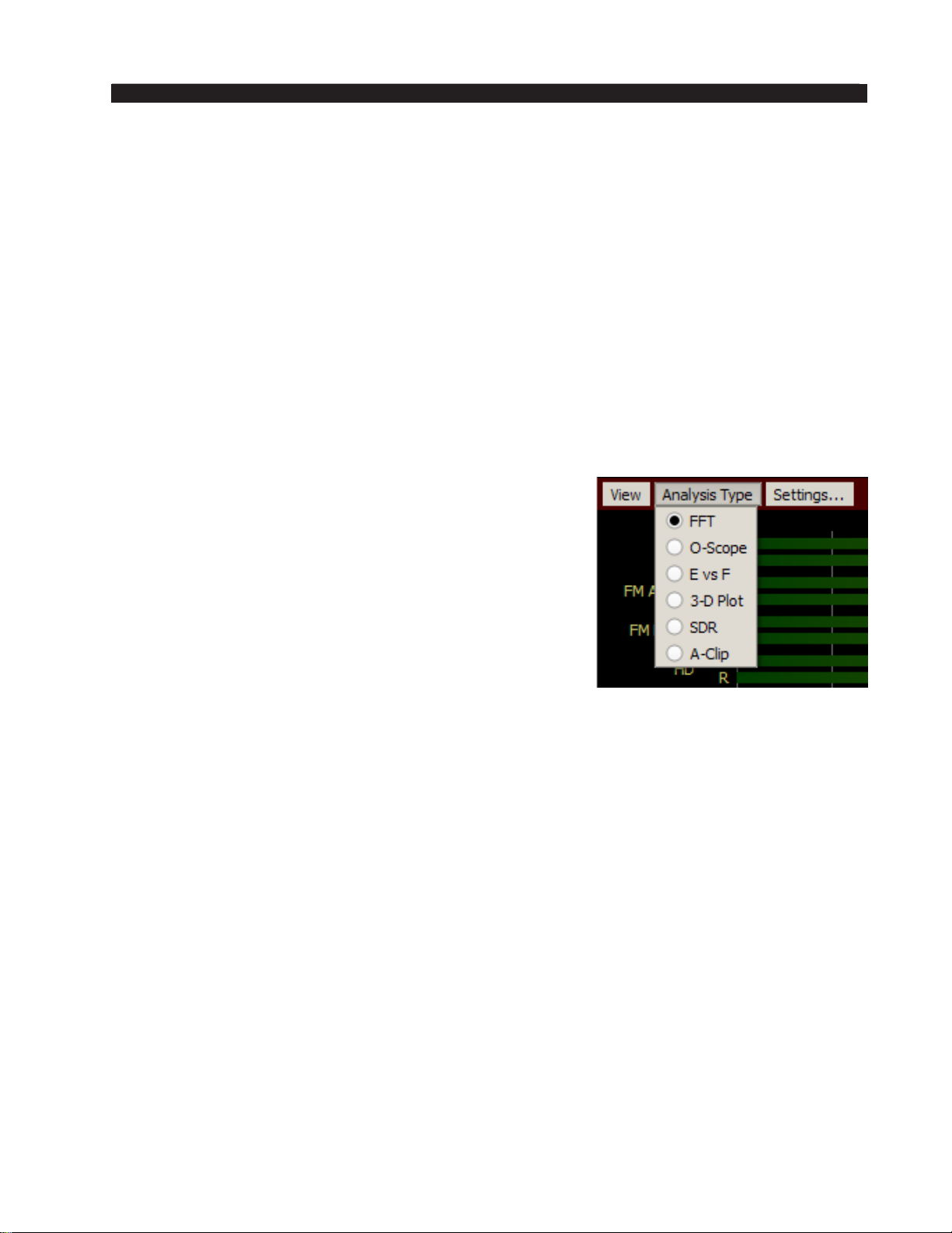
FM-531HD GURU GUI
Important Gain Reduction Display Metering Notes:
• The SST and ve band AGC utilize a meter scale that goes from 0dB at the top
to ‑30dB at the bottom.
• The 31‑band limiter, main FM and MPX limiter/clippers and BS‑412 algorithm
utilize a meter scale that goes from 0dB at the top to ‑15dB at the bottom.
• The VBMS meter does not need nor does it have a calibrated scale.
The 31‑band limiter does not need to do much work to gain its advantages. In fact,
less is more. Gain reduction deeper than 5‑6dB is not only unnecessary, but doesn’t
generate any further gains in loudness. Unlike the limiters in all other broadcast
audio processors, when 6dB, 10dB, or even more is required in order to generate
consistency and competitive loudness, the 31‑band limiter’s best sound quality and
loudness results when its bands are just being “tickled.”
Analysis Menu
The FM‑531HD is equipped with extensive processing
analysis features that show what the processing is doing and
by how much and when. The Guru GUI has a drop down
menu where the analysis to be viewed may be selected.
There are six options in this drop down menu:
• FFT – Displays the spectral output of the FM or HD
processing paths after processing. The FM display
includes any pre-emphasis being used in order to
present an accurate view of the signal actually being
sent to the transmitter by the FM‑531HD.
• O-Scope – Displays the audio waveforms at the output
of the FM or HD processing chains.
• E vs F – Displays the measured RMS Loudness within each of the 31 limiter
bands.
• 3-D Plot – A three‑dimensional plot of the audio, after processing, which displays
signal amplitude versus frequency versus time. The display has a ten second
historical window depth allowing some historical perspective about the FM or
HD audio after processing.
• SDR™ – Spectral Dynamic Range™ (a Wheatstone exclusive). This display
shows the amount of dynamic range remaining in each of the 31 FM or HD
limiter bands, after processing.
• A-Clip – This is FM‑531HD’s nal FM clipper activity display (another Wheat-
stone exclusive) that shows where in the audio spectrum distortion products are
being detected and reduced and by how much.
A detailed explanation of each analysis type follows.
FFT
This display shows a Fast Fourier Transform of the audio spectrum after process-
ing has been applied by the nal FM clipper or HD limiter. The FFT display’s high
resolution is useful for locating where in the audio spectrum certain signals are heard.
FM-531HD / May 2013
page 2 – 27
Page 61
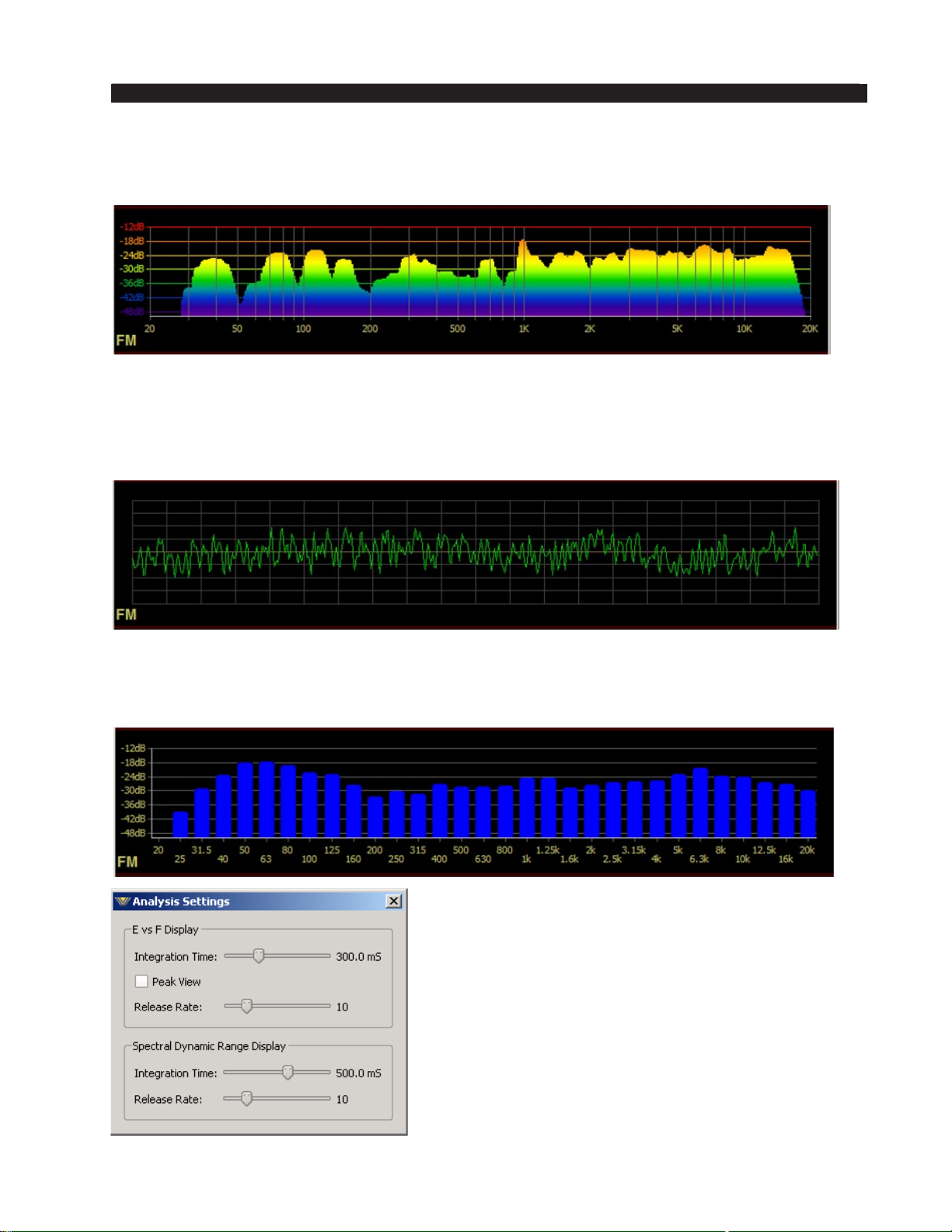
FM-531HD GURU GUI
With complex program material the FFT gives good visual feedback on the levels of audio
residing in different parts of the audio spectrum.
O-Scope
This is an oscilloscope‑type time‑domain display of the audio waveforms exiting the
output of the FM nal peak control sections. The FM O‑scope display will reveal what the
pre‑emphasized and clipped audio looks like.
E vs. F
This display represents the RMS Loudness generated in each band of the FM or HD
path’s 31 limiter bands.
The E vs. F display has a submenu (shown left) that
allows customization of the RMS Integration Time, the
display Release Rate, and whether or not peak levels
are to be displayed. The factory default Integration
Time is 300mS – the same as a standard VU meter –
which is also a fair estimator for how loud something
seems to the human ear.
The submenu also allows you to adjust timings for the
SDR display (below).
FM-531HD / May 2013
page 2 – 28
Page 62
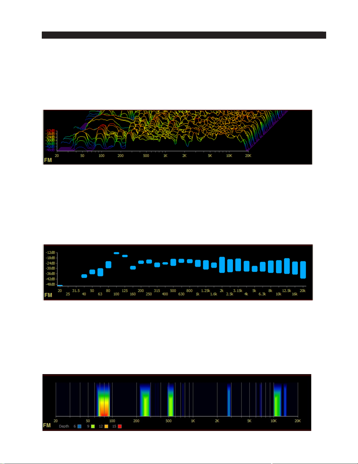
FM-531HD GURU GUI
3-D Plot
A 3‑D plot of the audio shows the last ten seconds of audio and what the audio levels
were at each frequency in the audio spectrum during that time.
The 3‑D plot can be very helpful when looking at how the audio spectrum has been
behaving over time. The higher the signal is in the plot, the larger the signal amplitude
at the frequency of the peak.
SDR™
During development of the FM‑531HD product we invented the Spectral Dynamic
Range™ Meter in order to assist us in evaluating what was happening in our new FM531‑HD
clipper as it managed the audio spectrum.
We made the SDR meter very easy to interpret – the longer the blue bars, the more
dynamic range there is between the peak amplitude and its RMS (loudness) level inside
each of the 31 limiter bands. Conversely, the shorter the bar’s length is, the denser the
audio is in that limiter band.
A-Clip
During development of our new FM clipper we realized that the only way to visually
monitor what the FM531‑HD clipper was doing was to invent a way to watch it work.
The A-Clip display was born out of that idea.
This display shows in detail, where in the spectrum the FM531‑HD’s distortion man-
agement is being accomplished, and by how much. Like a weather radar image, the “red-
der” the display, the more active the work being done in that part of the audio spectrum.
FM-531HD / May 2013
page 2 – 29
Page 63
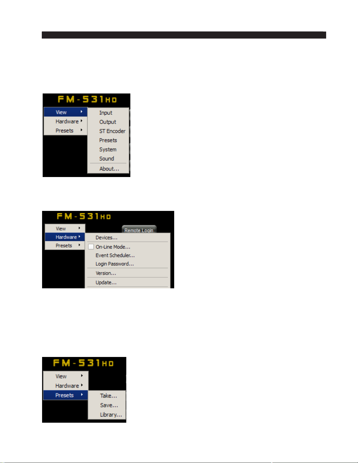
FM-531HD GURU GUI
Accessing Menu Options
Right clicking anywhere on the FM‑531HD Control Panel will open a pop up menu
tree with access to various items. The rst item in the list is View and it presents the user
with several choices for what he wishes to view.
Input: Makes the Input menu screen visible.
Output: Makes the Output menu screen visible.
ST Encoder: Makes the Stereo Encoder screen visible.
Presets: Makes the Preset management screen visible.
System: Makes the System screen visible.
Sound: Makes the Sound adjustment screen visible.
About...: Displays the GUI software version.
Next in the list is Hardware. When selected, the Hardware item opens up a list of
six items.
Devices...: Displays the Devices dialog
where the GUI is congured to communicate with FM‑531HD hardware.
On-Line Mode...: Shows or changes the
On‑Line status of the GUI.
Event Scheduler...: Opens the Event
Scheduler for viewing or editing.
Login Password...: Sets the Login pass-
word for the GUI when connecting remotely.
Version...: Displays the software and
rmware versions currently loaded in the
hardware.
Update…: Opens the hardware update dia-
log where a .VBN update le is selected for
download to FM‑531HD.
Next in the drop down list is Presets. When selected, the Presets item opens up a list
of three items:
Take...: Opens the Take Preset dialog to allow the current
preset to be changed.
Save...: Opens the Preset Save dialog with prompt for the
name and preset slot for the current settings to be saved to.
Library...: Opens the preset Library Manager which allows
presets to be packaged and moved to/from the hardware
and host PC, etc.
FM-531HD / May 2013
page 2 – 30
Page 64

FM-531HD PRO GUI
FM-531HD Pro GUI
Chapter Contents
Getting Started ...............................................................................3-5
Configuring The Pro GUI ..............................................................3-5
Connecting Directly Without a LAN ............................................................................3-6
PC System Requirements ..........................................................................................3-6
The Really Remote Connection! ................................................................................3-6
VPN ............................................................................................................................3-6
The FM-531HD and Internet Security Concerns ........................................................ 3-7
About DHCP and The FM-531HD ..............................................................................3-7
The FM-531HD Ports and Network Protocols ...........................................................3-7
Using The Pro GUI ......................................................................... 3-8
Dynamic Displays Region ...........................................................................................3-9
Frequency-Domain Graph .......................................................................................3-9
The FM-531HD Graphical Interface Operation .......................................................3-9
Metering and Analysis ............................................................................................3-12
Control Area Region ..................................................................................................3-14
Input Setup Menu ...................................................................................................3-15
Input Source .......................................................................................................3-15
Input Signal Presence ........................................................................................3-15
Input Failover ......................................................................................................3-15
Analog Input Gain ...............................................................................................3-16
Digital Input Gain ................................................................................................3-16
L/R Balance ........................................................................................................3-16
Phase Rotator .....................................................................................................3-16
HPF - High Pass Filter ........................................................................................3-17
Equalizer Menu .......................................................................................................3-18
EQ Enable ...........................................................................................................3-19
AGC + SST Menu ...................................................................................................3-20
What is SST? ......................................................................................................3-20
SST Controls Overview ......................................................................................3-21
SST Drive .....................................................................................................3-21
SST Gate Threshold ....................................................................................3-21
Ramp Rate ..................................................................................................3-21
Window Size ................................................................................................3-22
SST Linear/Adaptive Options ......................................................................3-22
A Word (or two) About Outboard Processors .....................................................3-23
FM-531HD / May 2013
page 3 – 1
Page 65

FM-531HD PRO GUI
Multiband AGC Controls ....................................................................................3-25
AGC Drive ....................................................................................................3-25
Gated Mode ................................................................................................3-25
AGC Gate Threshold ...................................................................................3-25
Band Coupling .............................................................................................3-26
AGC Backoff ................................................................................................3-26
AGC/Compressor Sidebar Menu .......................................................................3-27
AGC Attack ..................................................................................................3-27
AGC Release ...............................................................................................3-27
Compressor Attack .....................................................................................3-27
Compressor Release ...................................................................................3-27
AGC Mixer ...................................................................................................3-27
Stereo Enhance ...........................................................................................3-27
HD Limiter Menu ....................................................................................................3-28
31 Band Drive .....................................................................................................3-28
31 Band Limiter Sidebar .....................................................................................3-28
Threshold .....................................................................................................3-29
Attack ..........................................................................................................3-29
Release ........................................................................................................3-29
Lookahead Limiter ..............................................................................................3-29
Limiter Enable ..............................................................................................3-30
L/R Linked ...................................................................................................3-30
Final Limiter Drive ........................................................................................3-30
Limiter Threshold .........................................................................................3-30
Attack Time .................................................................................................3-30
Release Time ...............................................................................................3-31
Delayed Release ..........................................................................................3-31
VBMS .................................................................................................................3-31
Drive ............................................................................................................3-31
Style .............................................................................................................3-31
Output .........................................................................................................3-32
VBMS Frequency ........................................................................................3-32
VBMS Metering ...........................................................................................3-32
Digital Output .....................................................................................................3-32
L/R Reverse .................................................................................................3-33
Phase Reverse ............................................................................................3-33
FM Limiter Menu ....................................................................................................3-33
31 Band Drive .....................................................................................................3-33
31 Band FM Limiter Sidebar ..............................................................................3-34
Threshold .....................................................................................................3-34
Attack ..........................................................................................................3-34
Release ........................................................................................................3-34
Main Clip Drive ...................................................................................................3-34
Pre-Emphasis .....................................................................................................3-34
FM-531HD / May 2013
page 3 – 2
Page 66

FM-531HD PRO GUI
VBMS .................................................................................................................3-35
Drive ............................................................................................................3-35
Style .............................................................................................................3-35
Output .........................................................................................................3-35
VBMS Frequency ........................................................................................3-35
VBMS Metering ...........................................................................................3-36
Digital Output .....................................................................................................3-36
AES3 Digital .................................................................................................3-36
FM Diversity Delay ..............................................................................................3-36
Entering Delay Values Manually ..................................................................3-37
Stereo Encoder Menu ............................................................................................3-37
MPX Processor Style ..........................................................................................3-37
Composite Clipper ......................................................................................3-37
Look Ahead Limiter .....................................................................................3-38
MPX Process Drive .............................................................................................3-38
Multipath Controller ............................................................................................3-38
BS412 MPX Power Controller ............................................................................3-39
Pilot Injection ......................................................................................................3-40
Pilot Phase .........................................................................................................3-40
Stereo/Mono ......................................................................................................3-40
SCA 1 & 2 Gain ..................................................................................................3-40
TX 1 Level ..........................................................................................................3-40
TX 2 Level ..........................................................................................................3-40
Analog Output Type ........................................................................................... 3-41
Composite MPX ..........................................................................................3-41
Left/Right .....................................................................................................3-41
Left/Right De-Emphasized ..........................................................................3-41
Test Oscillator .................................................................................................... 3-41
System Menu .........................................................................................................3-42
Input/Output Settings Follow Preset Takes ........................................................ 3-42
Metering Data Over TCP/IP ................................................................................3-43
Remote Login .....................................................................................................3-43
Pro GUI Access ..................................................................................................3-44
Pro GUI Lock ......................................................................................................3-44
Status Indicators ................................................................................................3-45
Scheduler ...........................................................................................................3-46
Creating a Weekly Rotation Schedule .........................................................3-46
Creating a Long Term Rotation Schedule ................................................... 3-46
Deleting a Scheduled Event ........................................................................3-47
System Time .......................................................................................................3-47
Headphone Source ............................................................................................3-47
Headphone Control ............................................................................................3-48
FM-531HD / May 2013
page 3 – 3
Page 67

FM-531HD PRO GUI
Side Bar Region ........................................................................................................3-49
Presets ...................................................................................................................3-49
Save ........................................................................................................................3-49
Library ....................................................................................................................3-50
Locking Presets ..................................................................................................3-50
How to View Preset Changes .............................................................................3-51
Devices ...................................................................................................................3-51
Quick Save (QSave) ................................................................................................3-52
Title Bar Region .........................................................................................................3-53
Status .....................................................................................................................3-53
Device .....................................................................................................................3-53
Preset .....................................................................................................................3-54
Notes on Online and Ofine Working .....................................................................3-54
Accessing Menu Options ..........................................................................................3-55
View Menu Items ....................................................................................................3-55
Hardware Menu Items ............................................................................................3-55
FM-531HD Hardware Update ............................................................................3-56
Preset Menu Items .................................................................................................3-57
FM-531HD / May 2013
page 3 – 4
Page 68

FM-531HD PRO GUI
FM-531HD Pro GUI
The FM-531HD Professional Graphical User Interface (or Pro GUI) allows you
to adjust the processor and see, in real time, how the processor is reacting to the audio
passing thru it. Just like all of the Wheatstone Pro GUI’s, the FM‑531HD Pro GUI has
been carefully designed so that no adjustment is more than two mouse clicks away.
The FM‑531HD Pro GUI software allows you to control an unlimited number of
FM‑531HD’s via a standard Ethernet local area network (LAN). Utilizing TCP/IP and
UDP protocols, the GUI can be used to control any FM‑531HD processor from anywhere
with an Internet connection, including those behind rewalls and through VPN tunnels.
Getting Started
The FM‑531HD Pro GUI is a Windows™ based program and is designed to be
intuitive and straightforward in use. It is supplied as a self‑installing program execut‑
able that may be installed from any directory on the computer. The resulting les will
be installed under “\Program Files\Wheatstone\FM531HD.” After installation, select
the shortcut in the Windows Start menu to start the Pro GUI program.
To congure the FM‑531HD network connection, a basic familiarity with Windows
navigation techniques is assumed. If terms such as “left‑click,” “right‑click,” “double‑
click,” and “drag‑and‑drop” seem alien, operating the FM‑531HD’s remote GUI could
be a bit problematic.
Configuring The Pro GUI
The Pro GUI must rst be congured so that it can nd the FM‑531HD on the net‑
work. Install and then start the Pro GUI. In the GUI, click Devices>Add... to bring up
the Edit Device form (see page 2‑4).
Fill in the pet name you’ll be giving to the unit. In the IP Address eld below the
name ll in the IP address of the unit and then click OK.
Highlight the new the FM‑531HD device in the Devices list and click on the
Select button. Place the GUI online by clicking on the button to the left of the Status
message – its indicator should turn green. Once the GUI has been made aware of the
FM‑531HD’s existence in this manner, it will always appear in the list of the FM‑531HD
Devices and be instantly accessible from anywhere at anytime.
FM-531HD / May 2013
page 3 – 5
Page 69

FM-531HD PRO GUI
When connected to the FM‑531HD the status bar will indicate Online and the “Devices”
text will show the name of the FM‑531HD that it is currently communicating with (in
this example, the FM‑531HD has been named WERO). The status bar will also display
the name of the preset that the FM‑531HD you’re connected to is currently running.
When the Preset name is green it represents a preset (factory or user) that has been
recalled and is running with no changes made to it. If the Preset name is scrolling in Red
it means that the preset has had changes made or is a work in progress not yet saved to
the processor.
Connecting Directly Without a LAN
You can work without a LAN by connecting the FM‑531HD and the PC Ethernet
ports together with a standard Ethernet cable – either a straight through or crossover
cable may be used because the FM‑531HD has an auto‑sensing port.
NOTE: The controlling PC and the FM‑531HD’s network settings must be cong‑
ured to place them both on the same subnet!
PC System Requirements
Constraints for running the GUI are not extraordinary – the PC should be preferably
at least 1GHz in speed, running Windows 2000/XP or better. Screen resolution should
be at least 1024 x 768 pixels in order to get the full benet of the graphics used. You
need about 15MB of space on the hard drive for the GUI software and presets. The PC’s
LAN interface (NIC) should be 100baseT (100MHz) capable for best performance.
The Really Remote Connection!
One of our customers routinely adjusts his station’s Wheatstone processor from the
comfort of his company car. In order to accomplish this he connects it to his station’s
business LAN’s router, maps the unit’s IP address over to a “public” IP address via NAT
(Network Address Translation), and creates a hole in the rewall for this IP address.
This gives the Wheatstone “Internet” connectivity.
From the laptop in his car he connects to the Internet using his Verizon wireless
card, res up the GUI, connects to the IP address that is running in the box (NAT takes
care of the IP address differences), and Voila! He can adjust his Wheatstone processors
from anywhere. We will leave the myriad other ways in which the FM‑531HD can be
remotely controlled “wirelessly” up to your imagination!
VPN
Another way to connect remotely to the FM‑531HD is via VPN. A VPN, or Virtual
Private Network, is a private data tunnel between computer devices. It behaves just as if
the local and remote computers were sitting beside each other – devices connected via
VPN act like they are on one big LAN regardless of where they are physically located.
VPN tunnels can be congured both with and without data encryption. Setting up a VPN
is not difcult, but certainly beyond the scope of this manual.
FM-531HD / May 2013
page 3 – 6
Page 70

FM-531HD PRO GUI
The FM-531HD and Internet Security Concerns
The FM‑531HD does not act as a “web device” or “web server,” nor does it sup‑
port open ports to the Internet. Therefore there is no worry that someone could “hack”
into the FM‑531HD and use it as a pathway to the rest of the network to which it is
connected.
About DHCP and The FM-531HD
The FM‑531HD does not utilize DHCP – Dynamic Host Conguration Protocol
(or automatically assigned network addressing) – and needs to be assigned a “STATIC”
network‑unique IP address. Most DHCP servers assign addresses starting at the bottom
of the group 192.168.0.xxx. Therefore choosing an address high in that group, say
192.168.0.200, as a static IP address will likely keep it out of the way of the busiest
DHCP addressing.
However, it’s always wise to check with your local friendly network administra‑
tor to determine what static IP address is open and safe to use. Sometimes the local
network warrants the “Subnet” and “Gateway” values to be vastly different, but our
suggested starting values for the Subnet and for the Gateway should sufce for all but
the most complex situations.
The FM-531HD Ports and Network Protocols
The FM‑531HD uses both TCP/IP and UDP protocols to communicate with the
remote GUI. TCP/IP is used from the GUI to the FM‑531HD because its high reli‑
ability ensures that control changes sent to the FM‑531HD will be received. UDP
is used from the FM‑531HD to send and update metering and other real time data.
TCP/IP uses port 55900, while UDP uses port 60001, and, if 60001 is busy, tries the
next highest port until an idle one is found. Both TCP/IP and UDP ports must be open
for any rewall based connectivity.
FM-531HD / May 2013
page 3 – 7
Page 71
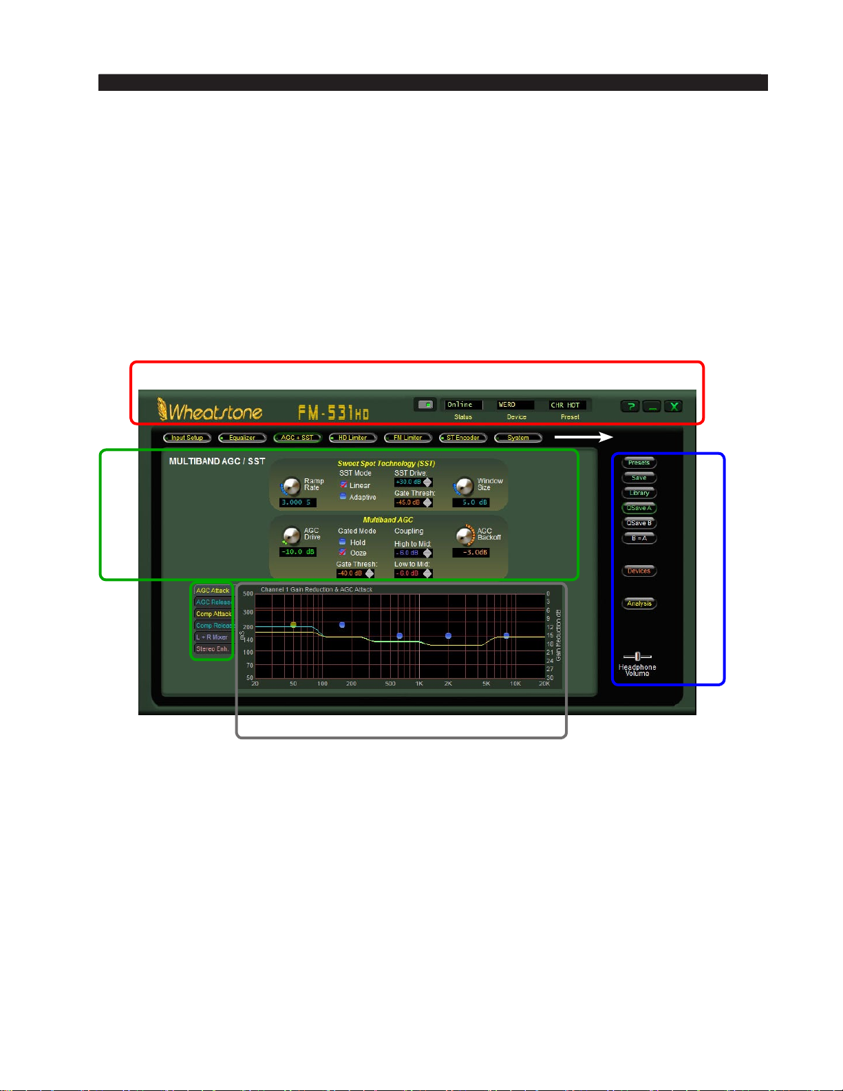
FM-531HD PRO GUI
Using The FM-531HD Pro GUI
The GUI may be positioned on the host computer’s screen by left‑clicking and holding
the top edge of the Title Bar and dragging the GUI to the desired position. In true Windows
fashion, the GUI may be minimized on the desktop (taken off the screen) and/or closed
by way of the familiar controls at the extreme top right.
Descriptions of the features and functions of the GUI will follow different discrete
regions of the screen; it will begin with the most eye‑catching region – the Dynamic
Displays – and then we’ll explain the Control Area above it, followed by the Side Bar
buttons, and lastly the Title Bar.
TITLE BAR
TABS
CONTROL
AREA
SIDE BAR
DYNAMIC DISPLAYS
FM-531HD / May 2013
page 3 – 8
Page 72
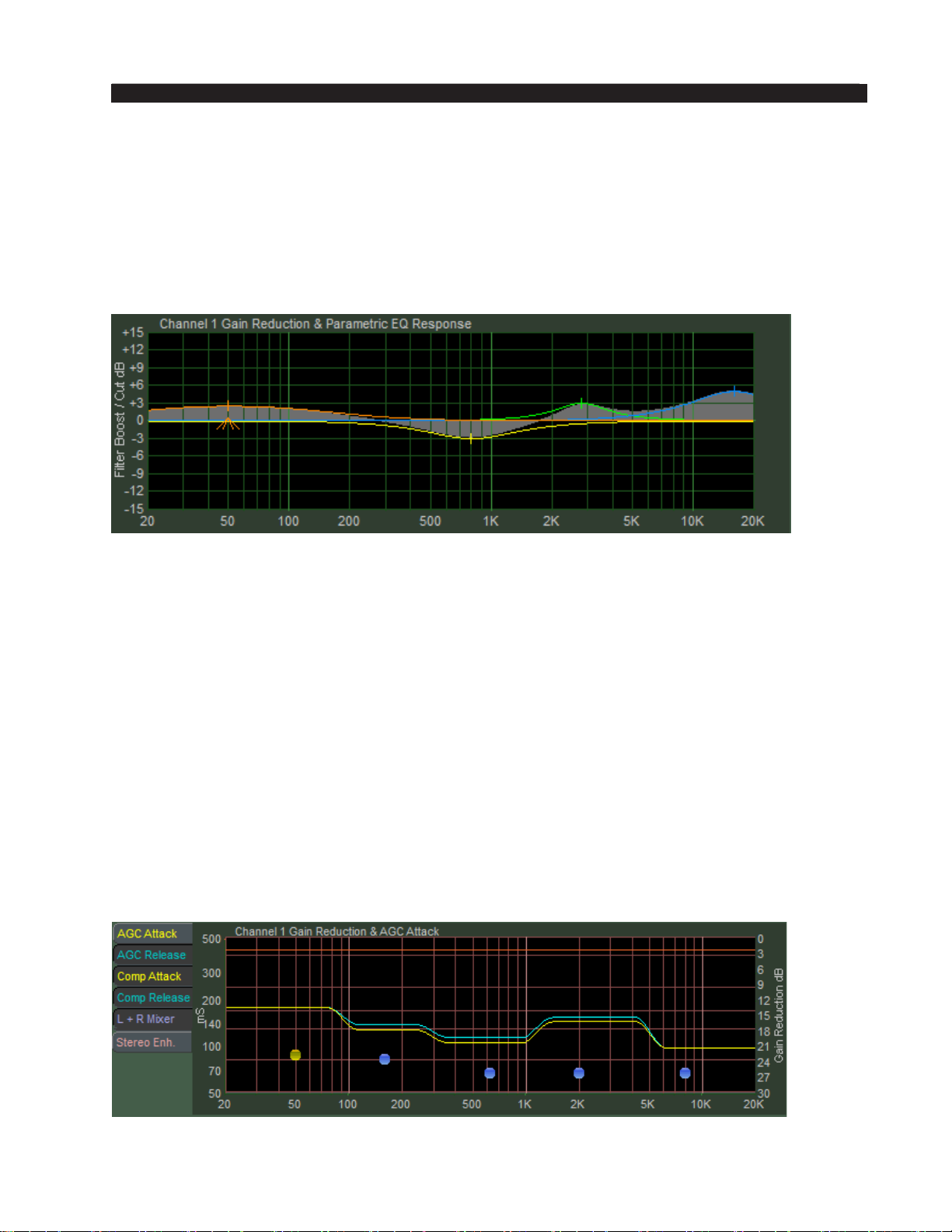
FM-531HD PRO GUI
Dynamic Displays Region
Frequency-Domain Graph
Visually the most important element on the main screen, and in fact dominating
the lower half of it, is a large graphical display depicting the standard audio frequency
range of 20Hz – 20kHz arranged in logarithmic fashion with gradations at selected
frequencies. The vertical axis scale changes according to its context.
FM-531HD Graphic EQ Display
The FM-531HD Graphical Interface Operation
Select either AGC+SST (pictured below), HD Limiter, or FM Limiter from the
buttons at the top of the Control Area. We’ve worked very hard on the design of the
Wheatstone graphical user interface to make it intuitive, friendly, and easy to navigate
and interpret in spite of the many number of controls the user has access to (well over
350).
Each of the processing section’s screens has a graphical area where not only visual
representations of processing activity are shown, but in some cases individual adjust‑
ments of different sections of the processing can be made.
All of the operating parameters of the ve band AGC and the 31‑band HD and FM
limiters can be individually adjusted by manipulating the positions of various “Dots”
on that section’s graphical screen.
Each of the blue dots on the screen represents the center frequency of a band. By
double clicking a blue dot (to highlight it and turn it Orange) and then dragging it with
the mouse, a particular parameter for each band can be adjusted.
FM-531HD / May 2013
FM-531HD 5 Band AGC/Compressor Adjustment Display
page 3 – 9
Page 73
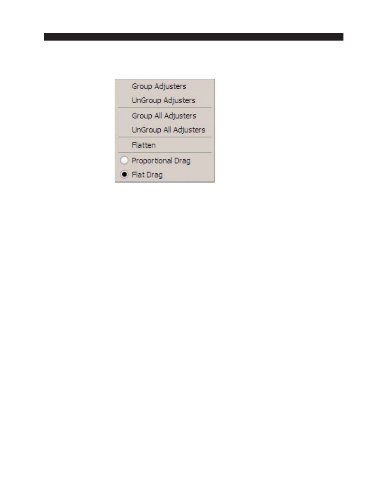
FM-531HD PRO GUI
By right clicking on the graphical display area with your mouse the following options
will appear:
First, a short tutorial….
By default, all adjusters (the blue dots) are Grouped. That is they are coupled to each
other so that if you grab one with the mouse (single left click and hold) and then slide
the mouse up and down, all blue points move up and down together.
If you double click a blue dot, it turns red to indicate that it has been selected, after
which it may be moved individually to anywhere along the vertical scale.
If you now double click another blue dot somewhere else on the line, it too will turn
red….
Now if you move the mouse to a point between the two dots selected in the above
steps, right click the mouse, and select UnGroup Adjusters, all the dots between the rst
two dots that were double clicked to turn them orange will also turn red.
At this point all of the dots can be individually adjusted up or down. If you now place
the mouse over the same graphical area, right click again and this time select Group
Adjusters the points between the rst two that you highlighted will turn back to blue. If
you then grab the line between these points with the mouse again (left click and drag)
you can move the entire line connecting the two highlighted end dots up and down, with
the two end points remaining anchored in place. Cool, eh?
Right clicking on the graphical area and selecting Group All Adjusters removes
all highlighted dots turning them blue again. Conversely, right clicking and selecting
UnGroup All Adjusters turns all (remaining) blue points red and they can now each be
individually adjusted.
The Flatten function, although next in the list, is best explained last….
Highlight a single dot again … any dot will do. Then right click the graphical area
and select Proportional Drag. Now left click any dot to the left or right of the dot you
highlighted and drag it up or down. See how the line behaves? It pivots at the point where
you highlighted the dot, and it bends at the point where you grabbed it with the mouse.
Virtually ANY curve can be created by following these steps. Now right click again and
this time select Flat Drag. Grab the line again… anywhere (left click and drag)… and
move it up and down. See how the line pivots at the highlighted point but remains at
above or below it as you raise and lower the line?
FM-531HD / May 2013
page 3 – 10
Page 74

FM-531HD PRO GUI
After these exercises the line is probably all messed up. You want to put it back to
where it was or at least make it all at again without having to move every single point
back, right? But how do you do that? It’s easy ... right click on the graphical area again
and select Flatten. If there were any points still highlighted orange you’ll want to rst
click Group All Adjusters before you select Flatten in order to turn them off. In any case,
when you nally click Flatten the line will return back to at and you may move it up
and down again with the mouse – this time as a whole.
To review:
Group Adjusters – Gangs the blue dots between two highlighted red points into a com‑
monly behaving entity.
UnGroup Adjusters – Disconnects any blue dots that were grouped by “Group Adjusters.”
Group All Adjusters – Gangs all the dots, turning them blue, regardless of their previous
highlighting state.
UnGroup All Adjusters – Un‑gangs the adjustment dots and turns them red, regardless
of any previous highlighting.
Flatten – Flattens into a horizontal orientation any dots not set to red.
Proportional Drag – Allows the dragging of adjustment dots to create slopes anchored
if desired to a single orange set point.
Flat Drag – Allows the dragging of dots together in a “at” orientation.
FM-531HD / May 2013
page 3 – 11
Page 75
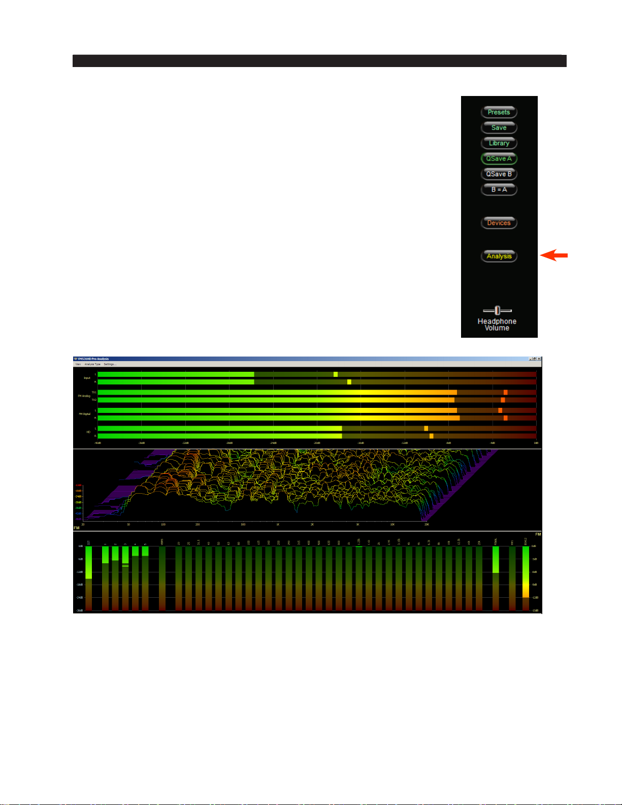
FM-531HD PRO GUI
Metering and Analysis
The FM‑531HD Pro GUI offers the same analysis options as the
Guru GUI. You can open a new graphics window to access the analy‑
sis features by clicking on the Analysis button in the sidebar region.
The analysis window is a separate window. In true Windows
fashion, the analysis window may be minimized on the desktop (taken
off the screen) and/or closed by way of the familiar controls at the
extreme top right.
FM-531HD / May 2013
FM-531HD PRO GUI Analysis Window
page 3 – 12
Page 76
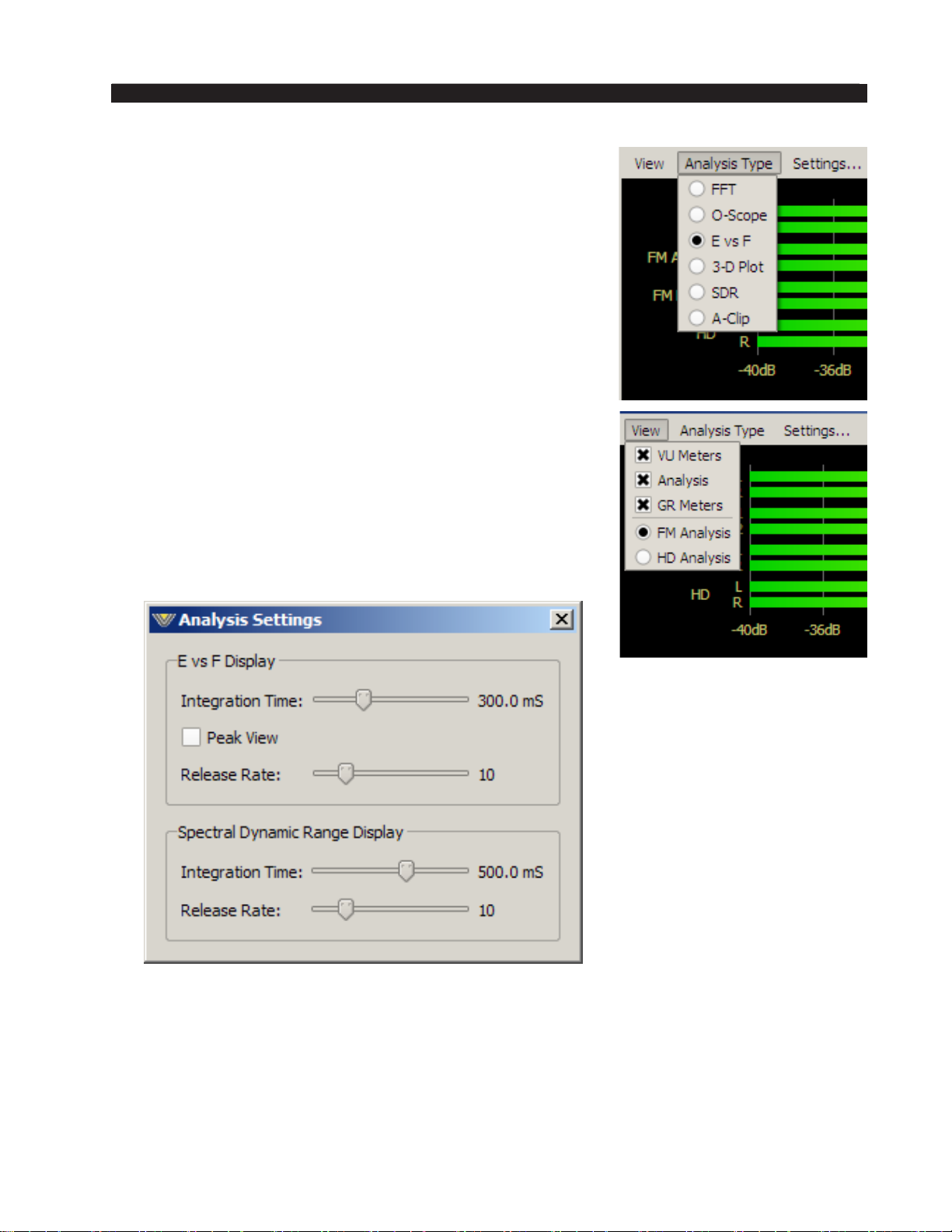
FM-531HD PRO GUI
To learn more about the different types of analysis avail‑
able, please see the section on Analysis for an in‑depth look
at what the different displays mean and how they can help
visually adjust the sound of the FM‑531HD. Accessing the
different visualizations is simple. At the top of the analysis
window is an option for Analysis Type. Click the text and
dropbox will let you select the analysis you want to look at.
You can also decide to minimize the display by choos‑
ing which panels you want to monitor. The default is the I/O
metering on top, the analysis in the middle window and the
gain reduction meters in the bottom window. With the view
tab, you can turn on or off any of those displays.
The Settings... button allows you to adjust the E vs. F
display to customize its RMS Integration Time, the display
Release Rate, and whether or not peak levels are to be dis‑
played. The factory default Integration Time is 300mS – the
same as a standard VU meter – which is also a fair estimator
for how loud something seems to the human ear.
The Analysis Settings window also allows you to adjust
timings for the SDR display.
FM-531HD / May 2013
page 3 – 13
Page 77
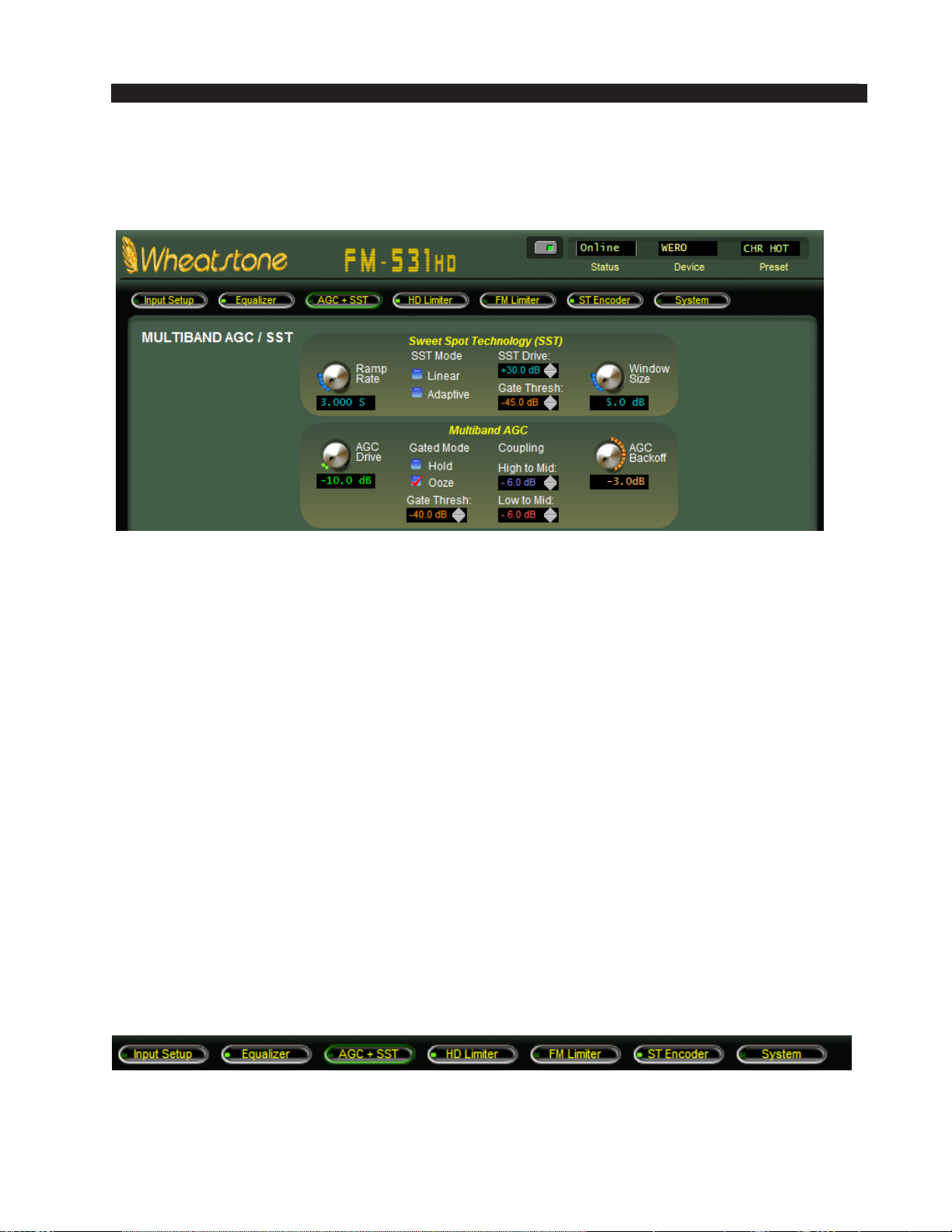
FM-531HD PRO GUI
Control Area Region
This is the large enclosed area directly above the graph and meters. The Equalizer
section is shown here as an example.
All of the knobs, faders, switches, and check boxes affecting the sound of the audio
processing are located within this half of the GUI. To operate them, either:
Place the cursor over the desired control, and use the mouse’s scroll
wheel to increase or decrease the control’s position.
OR
Click on the control, and slide the mouse to move the control – up or
right increases the control’s indicated position, down or left decreases
it. When using the mouse in this fashion (as opposed to using the scroll
wheel), the resolution of the control variation can be increased – made
ner – by holding down the keyboard’s Ctrl key while adjusting the
control as above.
OR
In most cases you can double click on the text that indicates the setting
value (for example, the window that reads X.XdB under the Analog
Input Gain knob on the Input Section) and a box will pop up where you
can enter an exact value and click OK.
From left‑to‑right across the upper portion of the graphical area are a series of buttons
corresponding to logically grouped processing sections in signal ow fashion in Input to
Output order.
A small green indicator at the left end of each button indicates if any signal processing
within that block is active. Left‑clicking a button opens the associated control panel to
gain access to the controls for that block of signal‑processing
FM-531HD / May 2013
page 3 – 14
Page 78
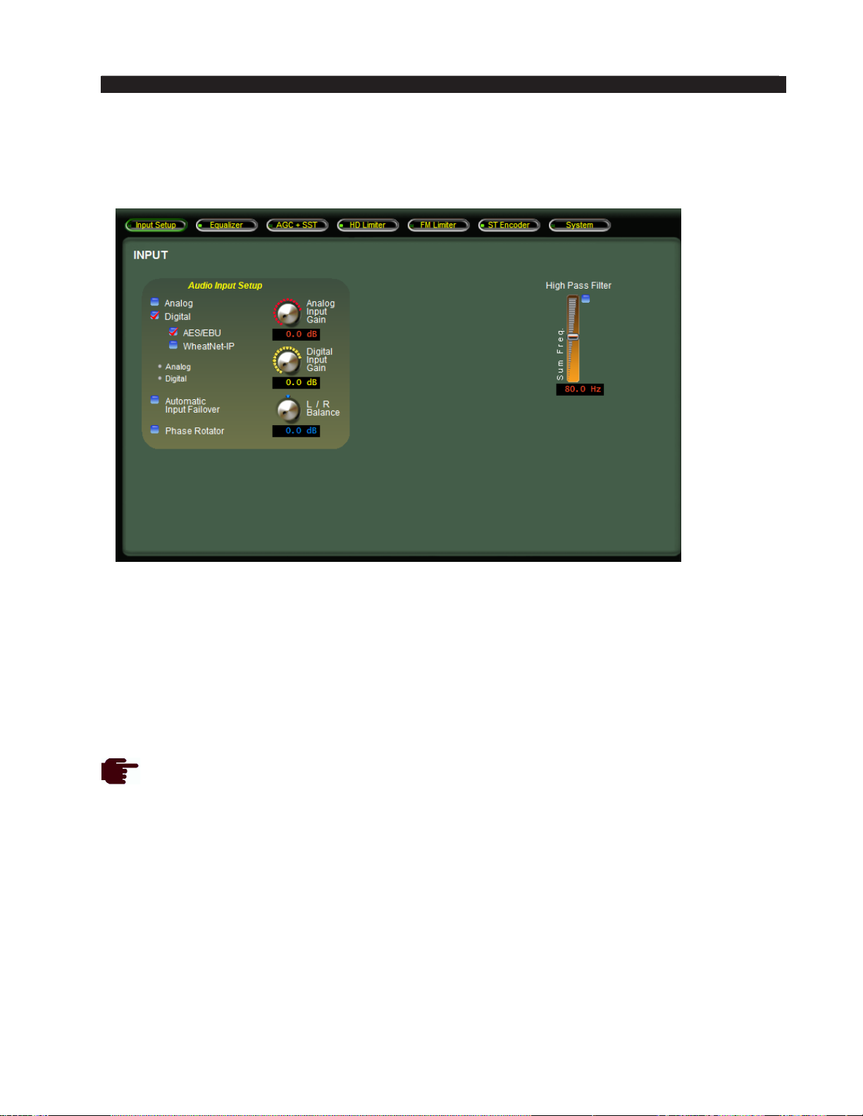
FM-531HD PRO GUI
INPUT SETUP MENU
This is the rst tab on the top far left of the Pro GUI. (Note: the screen that is cur‑
rently being displayed is indicated by a green outline on the selection tab).
The Input screen contains controls for the input source selection: Automatic Input
Failover, Analog and Digital input gain controls, input L/R gain balance, Phase Rotator, and the high pass lter.
Input Source
The Input Source can be selected as either Analog, which is the analog Left /Right input,
or AES, which is the AES3 digital audio input. If enabled, an option for WheatNet‑IP
may also be selected.
The currently selected input is shown by a red check mark. In the example above,
the input selected is DIGITAL with the AES/EBU option.
Input Signal Presence
Below the source selection check boxes are a pair of signal presence indicators. The
Analog indicator lights if there is a signal present at the analog input that exceeds the
threshold of ‑24dBu. The AES indicator lights if there is a valid AES signal present at
the digital input and it is above ‑48dBFS.
Input Failover
In the event the currently selected input source fails and the Automatic Input Failover
check box is checked, an alternate source of audio connected to the other input can
automatically be put on the air.
FM-531HD / May 2013
page 3 – 15
Page 79

FM-531HD PRO GUI
If the primary source was digital, the analog input will be selected immediately
if there are invalid bits in the data stream or missing audio data. Also, the analog
input will be selected after 30 seconds of a valid digital data stream having signal
levels below ‑48dBFS.
If the primary source was analog, then a silence sense timeout of 30 seconds
must elapse before the unit switches to the digital input. The audio failure sense
threshold is xed at ‑24dBu, and this combination with the 30 seconds timeout
is suitable for virtually all program types.
NOTE: The input failover option can only switch between an analog input and a
digital input. Failover from WheatNet‑IP to AES/EBU (or vice versa) is not supported.
Analog Input Gain
The Analog audio input gain can be adjusted by clicking on the knob and dragging the
mouse or touchpad to the right or left. The Analog Input Gain level can be adjusted over a
range of +12dB to ‑36dB.
Digital Input Gain
The AES/EBU and WheatNet‑IP Digital audio input gain can be adjusted by click‑
ing on the knob and dragging the mouse or touchpad to the right or left. The Digital
Input Gain can be adjusted over a range of +12dB to ‑36dB. This knob controls both
the AES and WheatNet‑IP input gain.
L/R Balance
Static level errors in Left/Right channel balance can be corrected by using the
L/R Balance knob. The Left/Right balance can be adjusted over a +/‑ 12dB range. This
control should only be used as a short term “Band‑Aid.” The relationship between left
and right should be corrected upstream if it is found the audio is out of balance.
Phase Rotator
Human voice is usually asymmetrical by nature, which means that it is usually
“peakier” in one polarity than the other. What the Phase Rotator algorithm does is x
these asymmetrical peaks. The way it works is by phase shifting the signal harmonics
relative to their fundamental frequencies. This action reduces the peak to average ratio
and enables an increase in apparent loudness with minimal audible detriment. We do
this because processing the audio for a symmetrical medium like FM is greatly simpli‑
ed if the waveforms are symmetrical.
Ordinarily, human voice looks like the waveform below. Notice how the width and
amplitude of the upper and lower signal peaks are different? This is “asymmetry,” and
it makes the processing of voice waveforms more difcult.
FM-531HD / May 2013
Human voice before Phase Rotator algorithm
page 3 – 16
Page 80
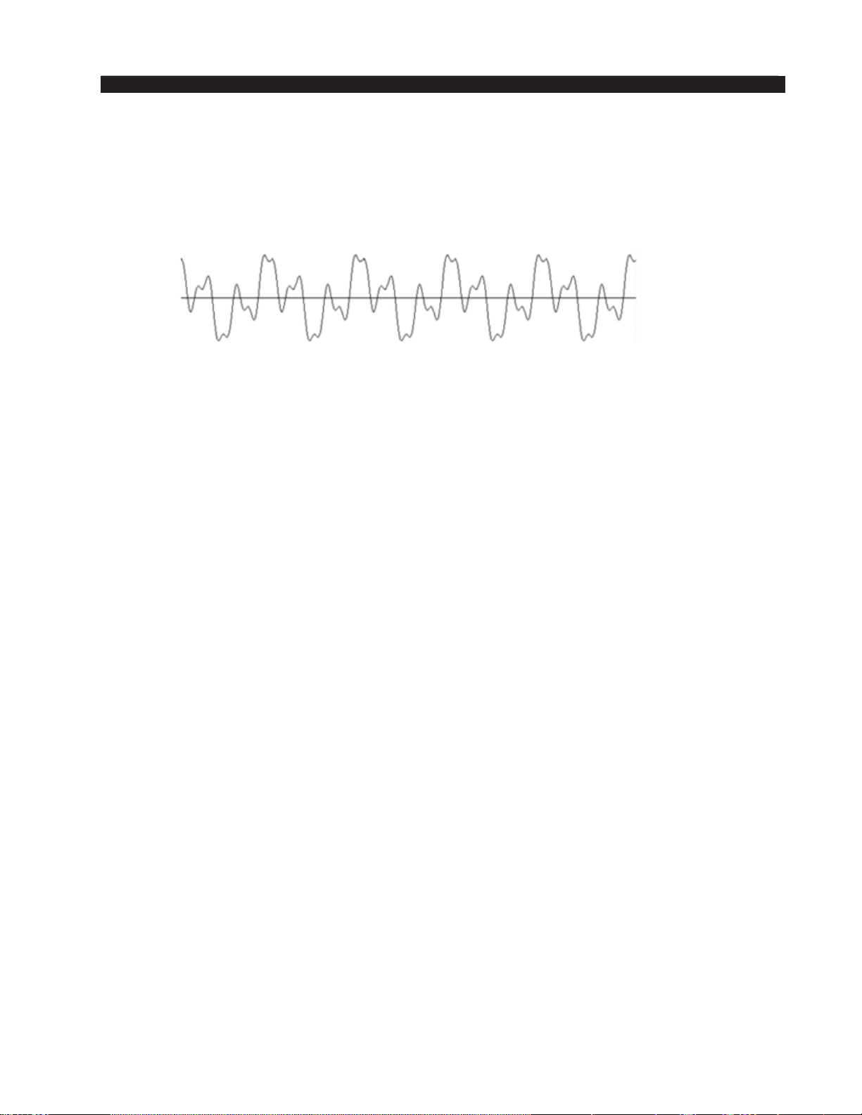
FM-531HD PRO GUI
After passing through the Phase Rotator the same voice appears like the waveform
below. Notice how the upper and lower portions of the waveform now have equal distri‑
bution? No information is lost and, more importantly, no harmonic or intermodulation
distortion is created by the Phase Rotator. The only thing that happens is that the signal’s
phase relationships are rearranged to make the waveform energy more uniform in polarity.
Human voice after Phase Rotator algorithm
HPF – High Pass Filter
The High Pass Filter is used to remove inaudible and unnecessary subsonic energy
from the audio signal prior to it being processed. By removing this energy, processing
is cleaner and modulation energy is not wasted by transmitting sounds that will not be
perceptible to a listener.
The High Pass Filter also removes subsonic energy that could upset the operation of
equipment later in the audio chain, such as the AFC loop in the FM exciter.
The High Pass Filter has two operating modes:
Off – If the High Pass Filter box is not checked the High Pass Filter is not enabled.
Stereo – If the High Pass Filter box is checked the High Pass Filter operating mode
is stereo and both left and right audio channels are treated equally by the high pass lter
frequency.
FM-531HD / May 2013
page 3 – 17
Page 81
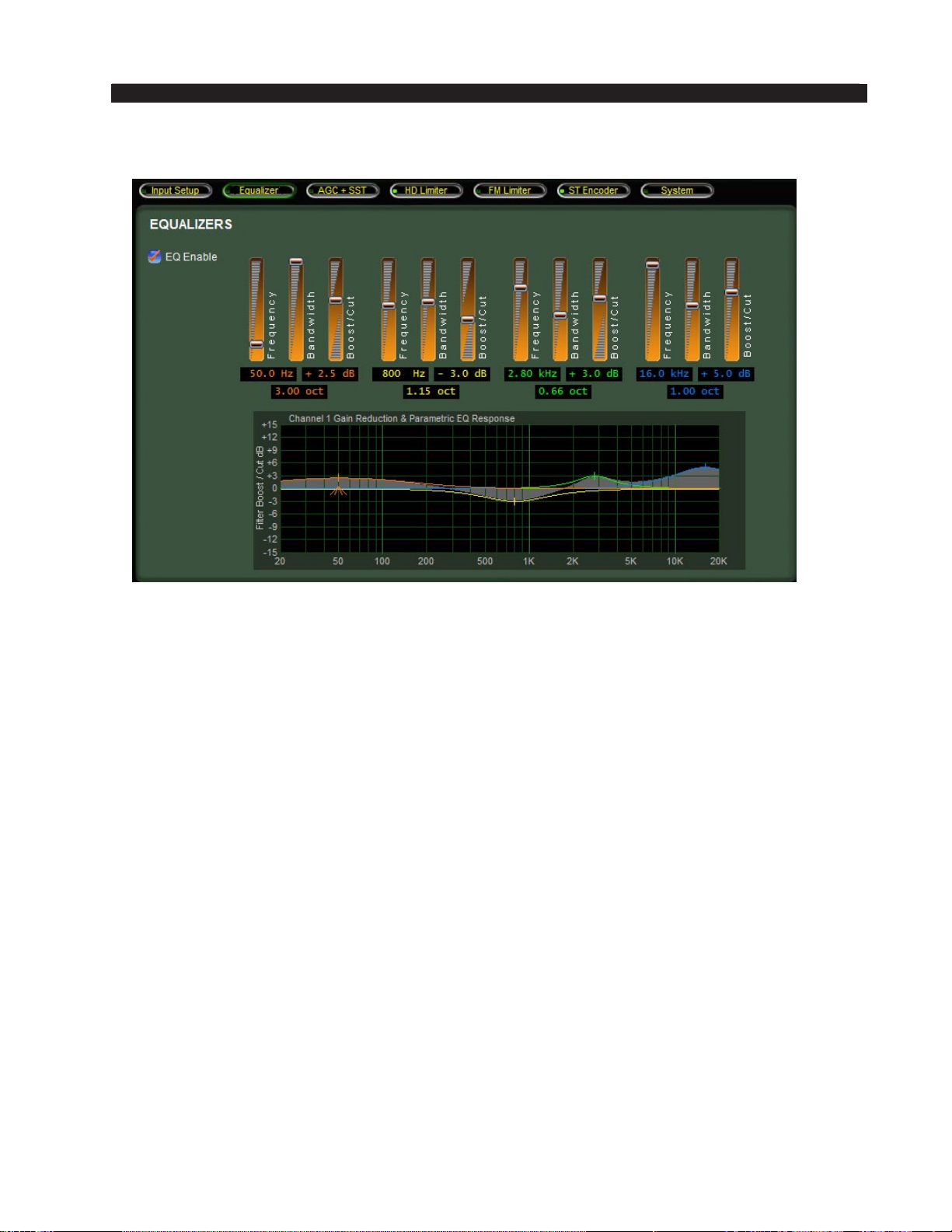
EQUALIZER MENU
FM-531HD PRO GUI
The Equalizer tab has four identical and independent bands. Each of the four bands
can be switched in or out independently, and is fully adjustable in three ways:
Center Frequency — 20 Hz to 20 kHz.
Bandwidth — 0.2 to 3.0 octaves.
Boost/Cut — +/- 14.0dB.
The controls of the equalizer may be manipulated in three ways:
1. The rst is by directly clicking on and dragging the control sliders in the equalizers
control screen. As the controls are manipulated, numerical representations of the
control settings appear in the boxes below the band that is being adjusted.
2. The second method of adjusting the equalizers is by directly manipulating the actual
curves on the graphical screen below using the mouse. See the next page for how
to manipulate the curves directly.
3. The third method is by direct value entry. By double clicking on the value boxes
underneath each slider, a dialog opens up which allows keyboard entry of the op‑
erating values for each equalizer section. Once the value has been typed into the
entry box, clicking the OK button or hitting the keyboard Enter key will make the
value active. Note that the direct entry method is controlled by a lookup table of
all possible values. If an entry is made that is not in the lookup table, the closest
lookup table entry will be made active.
FM-531HD / May 2013
page 3 – 18
Page 82
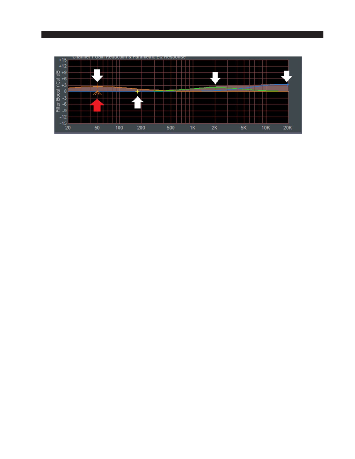
FM-531HD PRO GUI
Clicking on the crosshair of a curve (see white arrow) and holding the left mouse but‑
ton down as you drag the mouse will move the curve to any frequency (left or right move)
as well as adjust the curve’s level (Boost or Cut) above or below the 0dB reference line
(up or down move).
Clicking on the small “tent” underneath (see red arrow), and holding the left mouse
button down while sliding the mouse left or right allows changes the bandwidth, or “Q,”
of the equalizer section.
EQ Enable
This is the master Equalizer In/Out button. When this box is checked the equalizer
section is enabled.
FM-531HD / May 2013
page 3 – 19
Page 83
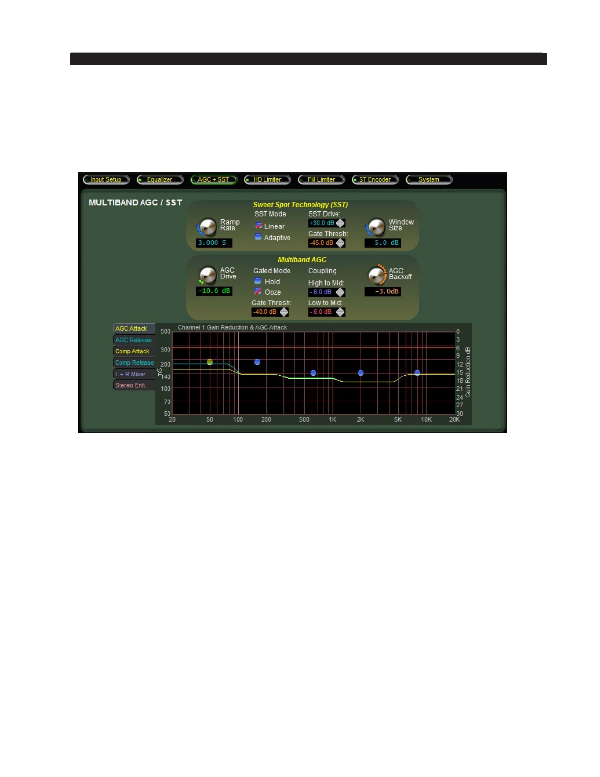
FM-531HD PRO GUI
AGC + SST MENU
The FM‑531HD has three sections dedicated to dynamics control, the Automatic
Gain Control (AGC), Compressor, and Sweet Spot Technology™ (SST). All three are
inextricably linked by DSP algorithms which logically connect and control them. All
three sections will be collectively discussed in one chapter rather than separately.
What is SST?
Unique to Wheatstone models of processing is a special algorithm called SST, which
stands for Sweet Spot Technology™. The SST incorporates control signals from the
input audio, the multiband crossover, and the AGC and Compressor behaviors in order
to derive a special control signal that is used to force the multiband AGC/Compressor
to operate within a specied gain reduction window. By doing so, the medium and long
term “sound” of the processor is quite stable as program elements and incoming audio
levels wander about.
Without the contribution of the SST, the AGC and Compressor sections would not
be able to maintain as consistent a spectral and dynamics texture over widely ranging
signal input conditions. In fact, they would have little advantage over the technology used
for generations in other audio processors which all suffer from the inability to manage
long‑term spectral consistency.
A “broadband AGC” is not used prior to the AGC and Compressor because such
devices know nothing about the output of the multiband section, and it is this output
that determines the overall texture of how a radio station sounds on the air. By using a
multiplicity of control signals the SST is able to calculate a correction signal that exactly
manages the behavior of the multiband AGC and compressor in order to create a consistent
signature sound across a very wide variety of input sources and audio levels.
FM-531HD / May 2013
page 3 – 20
Page 84
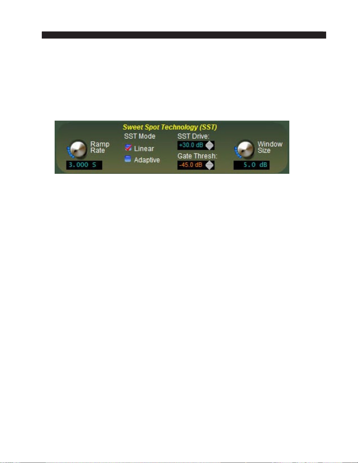
FM-531HD PRO GUI
The automatic gain control (AGC) itself operates in ve frequency bands, and its
medium‑term operation is a special derivative of the type of program‑related processing
occurring in the Compressor algorithms. While the SST section operates in Left/Right
mode, the AGC and Compressors operate on the program content’s Sum and Differ‑
ence – the highest signal, whether it’s in the sum or difference channel, determines the
amount of processing to be applied to both channels.
SST Controls Overview
SST Drive
The SST Drive control adjusts the amount of signal fed to the algorithm that mea‑
sures the dynamic behavior of the ve band AGC. The higher the SST Drive setting the
deeper the control depth in the algorithm – which allows it to operate over the widest
possible program dynamic range.
A typical amount of SST control depth that affords the best tradeoffs in operation
will be somewhere between ‑12 and ‑15dB as seen on the gain reduction display. Note
that there is no harm in generating more or less control depth as long as one understands
that more control depth affords greater long term control of audio levels and less control
depth affords less. The overall control range is +30.0dB to +40.0dB.
SST Gate Threshold
The SST algorithm has been provided its own Gate Threshold so that its operation
may be optimized when it is combined with the ve band AGC. Typically the SST Gate
Threshold will be set several dB higher (less negative) than that of the ve band AGC.
The overall control range is ‑60.0dB to ‑35.0dB.
The SST Gate Threshold control sets the audio input level where SST correction is
turned off and its gain is frozen.
Ramp Rate
In order for the SST to behave with all types of program requirements it must have
its speed of correction tailored for the application and this is what the Ramp Rate control
does. The control is calibrated in units of time, and therefore describes the rate at which
the SST causes more or less activity to occur within the ve band AGC/Compressor.
A good typical starting value for SST Ramp Rate is 4.000 seconds. The full control
range is 2.000 to 7.000 seconds.
FM-531HD / May 2013
page 3 – 21
Page 85
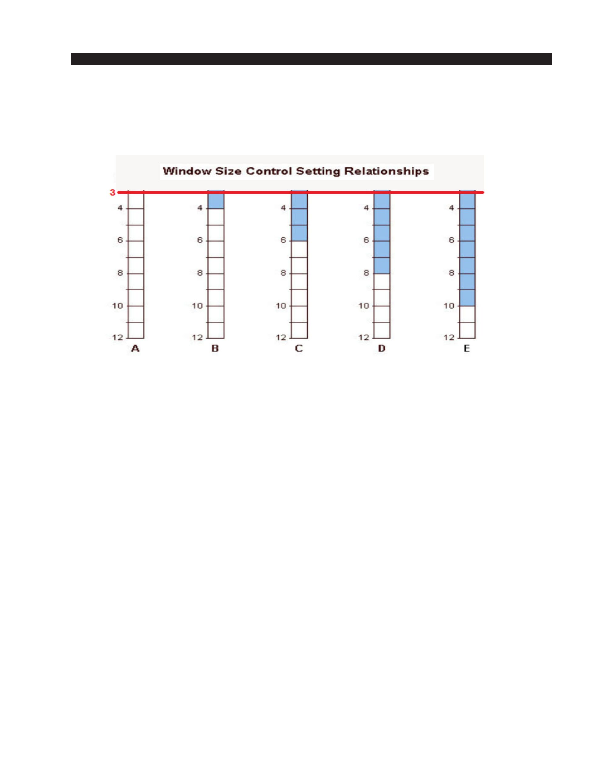
FM-531HD PRO GUI
Window Size
Because the SST is responsible for maintaining the operation of the ve band AGC
in its “Sweet Spot” the size of that sweet spot needs to be able to be set for different
kinds of program requirements. See the graphic below for some examples:
The graphic shows the full potential of the control for a visual explanation
of how the control works. The red line indicates the user adjustable lower
limit of the SST at 3dB. The upper limit is 12dB
The size of the shaded areas in the above graphic serve to demonstrate the size of
the error (in dB) permitted to occur within the ve band AGC before the SST corrects
it. It is important to note that the SST has no control over allowing the ve band error
to go positive – that is specically handled by the ve band AGC itself. As the shaded
areas show, the larger the Window Size, the larger the “error” allowed by the SST before
correction takes place.
Very small Window Size settings can cause the SST to continuously try to correct for
minute behavioral errors within the ve band AGC. Likewise, very large Window Size
settings will allow large AGC errors to go uncorrected. Settings at either extreme, while
probably not doing anything wrong to the audio, are not particularly useful, especially
when these settings are on the smaller Window size, which is why this control has been
limited to 3dB as the lowest setting.
The usual setting of the Window Size control for the majority of program content
will be between 4.5dB and 7.5dB. The full range of the control is 3dB to 12dB.
SST Linear/Adaptive Options
The two nal controls are options for the SST, Linear and Adaptive. Only one
can be chosen. In the Linear mode, the SST makes adjustments to the ve band
AGC/Compressor at the same user dened rate regardless of program level. In the adap‑
tive mode, the SST makes adjustments to the 5 band AGC/Compressor at faster rate than
selected by the user if there is a dramatic change in program level. The linear mode is
advised in most cases. The adaptive mode is suggested in cases where program levels
vary widely. To defeat the SST, make sure both options are unchecked.
FM-531HD / May 2013
page 3 – 22
Page 86

FM-531HD PRO GUI
A Word (or two) About Outboard Processors
There are a number of popular outboard AGC/Compressors on the market that
have traditionally been used in front of all‑in‑one processors to achieve one or all of
the following:
• A different sonic texture than what is available in the main processor.
• The ability to bypass functions in the main processor (usually located at a
transmitter) and bring the “meat” of the controls to the studio end for endless tweaking
• Compensation of a poorly designed AGC in the main processor.
• Level protection for an STL path
• Level enhancement for ratings encoders.
Of course, we feel that the SST algorithms in the FM‑531HD eliminate most of
the concerns mentioned above. By processing as we do with SST, we have removed
the need for a wideband AGC directly in the audio path while keeping the benet of
what a wideband AGC can do (which is usually keeping the processing after it in its
“Sweet Spot”... thus “Sweet Spot Technology” or “SST”). No other all‑in‑one pro‑
cessing solution like the FM‑531HD processes with the accuracy of SST.
We also feel that the amount of control in our Pro GUI allows the user to virtually
set the FM‑531HD to whatever sonic texture they can think of, eliminating the need
for an outboard box to emulate the same.
The advent of internet connectivity allows processors in even the most remote loca‑
tions to be easily adjusted via a remote GUI. In most cases, the need for the processor
to be “at the studio” so it can be accessed is a thing of the past.
We also feel that if the levels in your plant are properly calibrated, there should be
no need for an AGC in front of an STL path. Almost all professional broadcast gear
that would be in‑line with a console before and including the STL will have as much if
not more headroom than your broadcast console. If non‑broadcast or non‑professional
gear is in your audio path, it should be replaced ASAP with a suitable device. Con‑
sumer grade equipment in the program line is never advised and will only spoil the
nancial investment you have made in the FM‑531HD.
All this being said, there may be some cases where, no matter what, an outboard
processor is needed or desired.
• Ratings Encoders – We have found that ratings encoders do need a “steady
diet” of incoming level in order to be happy in certain cases. We nd this to be
problematic at stations that are automated for much of their broadcast day (where
a human is not present to make adjustments to the source level on the console).
In many cases, levels can be as much as 10dB different from source to source
when care is not taken when audio les are ingested into a playout system. While
SST can easily compensate for these level differences, a 10dB drop in level will
not make a barefoot ratings encoder happy over the course of a 3‑4 minute song,
causing it to alarm and email and page the world. On weekends, that can be a
BIG pain.
The BEST way to x this problem is to make sure there are standards in place
for proper levels when recording into your playout system. Unfortunately, that isn’t
FM-531HD / May 2013
page 3 – 23
Page 87

FM-531HD PRO GUI
always practical in this era of downsizing as there aren’t enough warm bodies to do
the work. So, for stations that feel they need to use a processor ahead of a ratings
encoder, we suggest setting the FM‑531HD multiband control gate between ‑30dB
and ‑20dB and placing the SST in Linear mode. If aggressive AGC is needed, adjust
the AGC Backoff in the FM‑531HD towards 0dB.
• Reverb – Reverb was originally used as a way to increase density into older
AM transmitters when processing wasn’t sophisticated enough to do the same.
The effect of reverb not only did the trick at the time, it also added a pleasant
sonic texture to the audio that is desired by many stations today. The problem
with reverb units is that the input level controls everything about how the reverb
will sound on the air if the unit is placed directly into the program chain.
A pre‑processor is traditionally used ahead of a reverb unit to prevent excessive
reverb due to sloppy levels from a console. A pre‑processor also sustains program
audio somewhat to get the most out of the decay effect in a reverb unit. Just like
adding an AGC to enhance levels to a Ratings Encoder, the same steps should be
taken to adjust the FM‑531HD to “mate” with the outboard processor. If reverb is
sidechained into a microphone processor and not directly in the audio path, no special
adjustments of the FM‑531HD need be made.
• Analog Telco STL or Aural STL – Older analog telco lines sometimes need
some pre‑processing in order to keep signal to noise ratios high. Some have
indicated the need for pre‑processing before an aural STL to prevent overshoot.
Again, if you feel the need to use a pre‑processor in either of these situations,
adjustments to the FM‑531HD should be made in concert with the suggestions
above.
It is not recommended that SST be defeated in the presence of an outboard AGC.
If you do choose to defeat the SST, the gain control will become xed at ‑12dB and
adjustment of the 31‑band limiter drive may need to be made for any offset that the
xed level creates. It is because of these changes that slowing down SST and the ve
band AGC/Compressor be exhausted before sections of the processor are bypassed.
FM-531HD / May 2013
page 3 – 24
Page 88
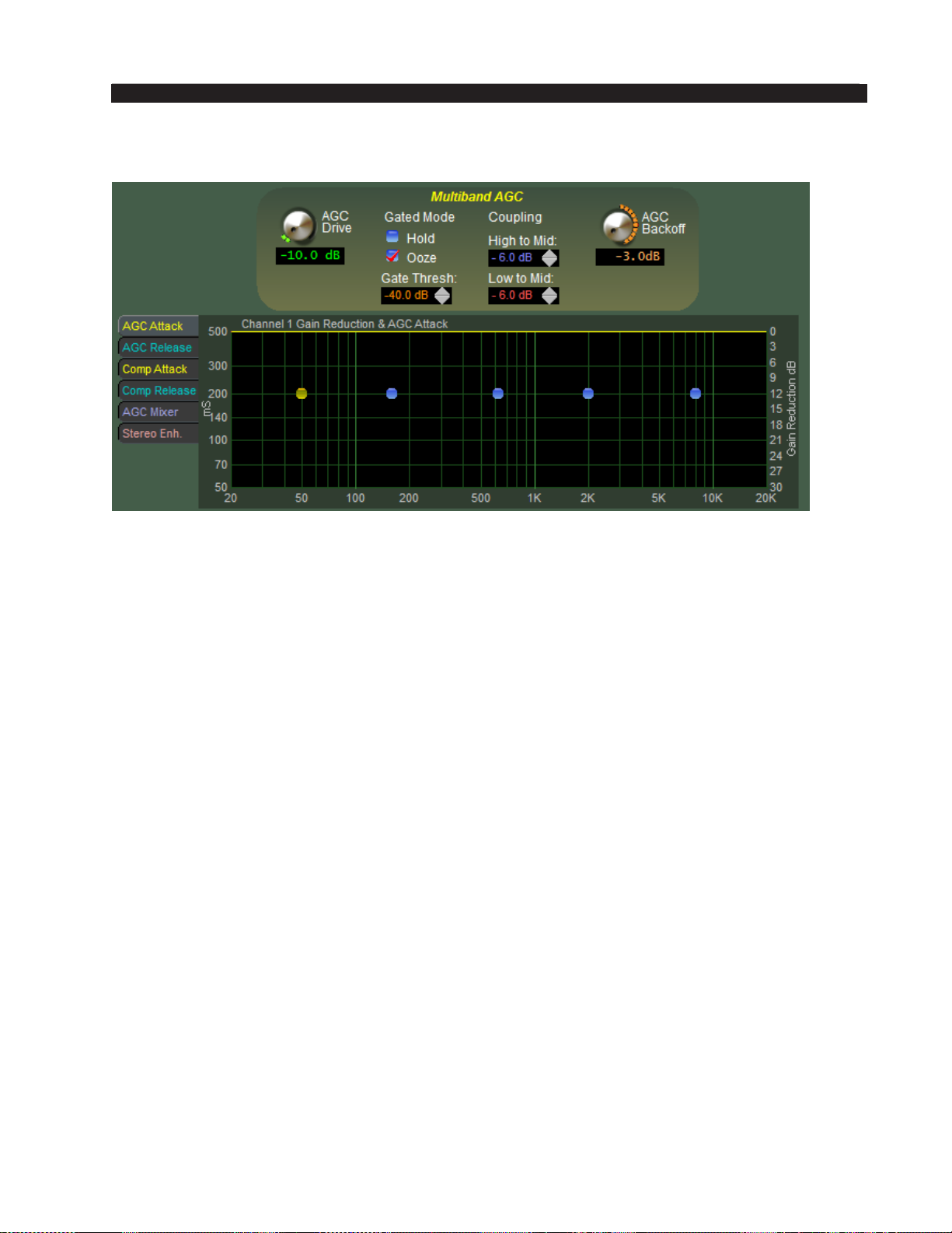
FM-531HD PRO GUI
Multiband AGC Controls
AGC Drive
The AGC Drive control adjusts the amount of signal into the AGC/Compressor,
primarily determining the amount of compression that can be achieved. Driving harder
(higher numbers) results in a more consistent on air sound, with an increased capabil‑
ity to pull up low passages in program material. Less drive creates a more “gentle” on
air sound and has less capability to bring up low passages.
The AGC Drive control simultaneously adjusts the sum and difference channels.
The range of this control is ‑12.0dB to +6.0dB.
Gated Mode
The Gated Mode controls determine how the AGC behaves in the absence of audio.
When Ooze is selected and the audio input falls below the AGC Gate Threshold,
rather than the gains of the bands “holding” they will slowly return towards 0dB.
This setting may be useful for formats that contain material with very wide dynamic
range or for certain speech‑based formats where the “Gate Delay” setting may not be
appropriate.
When Hold is selected and the audio falls below the AGC Gate Threshold value
the gains of the ve bands will “freeze” at their current values and will hold at those
values until audio is present that is above the AGC Gate Threshold. This prevents the
increasing of gain in the absence of audio which would likely increase background
noise.
AGC Gate Threshold
The AGC Gate Thresh control sets the audio level below which the audio gain re‑
duction values are held until audio returns. The control can be set to OFF or adjusted
over the range of ‑79.0dB to ‑20.0dB.
FM-531HD / May 2013
page 3 – 25
Page 89
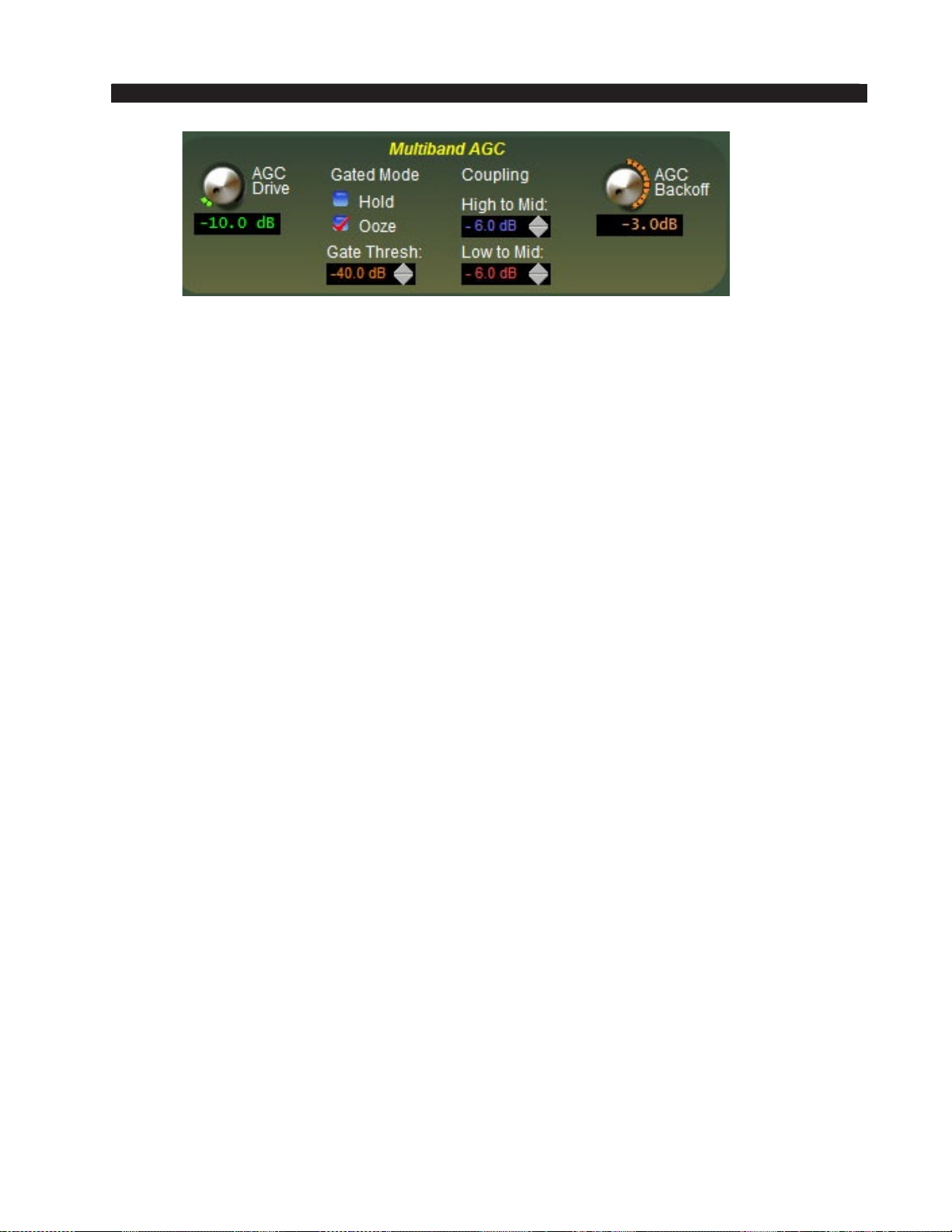
FM-531HD PRO GUI
Band Coupling
The Coupling control has one specic purpose – to keep the gains of bands 1, 2, 4,
and 5 from exceeding the gain of band 3 when those “outer” bands are “ungated.” This
prevents unnatural gain rush‑up by those bands when such behavior would be undesir‑
able. Without the “Coupling” feature the gains of the bands at the frequency extremes
can increase their gain and cause a spectrally incorrect sonic mixture at the output of
the ve band section.
Band 3 was chose as the “master” band for the high and low coupling control because
that band is in the approximate center of the audio spectrum.
The Coupling control may be adjusted over the range of “0dB” to “‑6dB” (High to
Mid) or “0dB” to “‑12dB” (Low to Mid). When each coupling setting is set for “0dB”
bands 1, 2, 4, and 5 can never have more gain than band 3. Such a setting is useful in
formats such as Classical and Jazz that typically would not wish the spectral “correc‑
tion” caused by the outer bands increasing their gain but still need those bands to reduce
their gains when appropriate.
In typical programming situations the best setting of the Coupling control will likely
be somewhere between ‑2.0dB and ‑4.0dB. ‑6.0dB (‑12dB Low to Mid) was chosen
as the maximum setting. Any further decoupling at the point allows the outer bands to
“wander” around too much, causing an unnatural spectral buildup on some material.
AGC Backoff
The AGC Backoff adjusts the processing balance between slower AGC action and
faster compression.
With the AGC Backoff control set at “0,” the audio gain control is primarily due to
slower AGC action, and therefore short term program dynamics are largely unaffected
unless they exceed the AGC gain reduction by at least 1dB. In that case momentary gain
reduction by the compressor will place the gain where it needs to be to return control
to the AGC.
With the AGC Backoff control at the other extreme, or ‑6dB, gain control is primarily
due to fast compression and short term dynamics will be aggressively controlled. The
setting of the AGC Backoff control allows the audio compression texture to be modi‑
ed from a gentle, almost unobtrusive control (AGC Backoff between “0” and about
minus 2.0dB), to very obvious compression (AGC Backoff control at “‑3.0dB” or greater
negative numbers) creating a sound that is similar to vintage compressors and limiters
from the 1960’s.
Note that regardless of the setting of the AGC Backoff control, the AGC and Com‑
pressor stages operate with their algorithms linked mathematically and there is no other
method for changing the relative thresholds between the AGC and compressors. If for
some reason “less” AGC control signal is desired, it may be achieved by lengthening
the AGC attack times.
FM-531HD / May 2013
page 3 – 26
Page 90
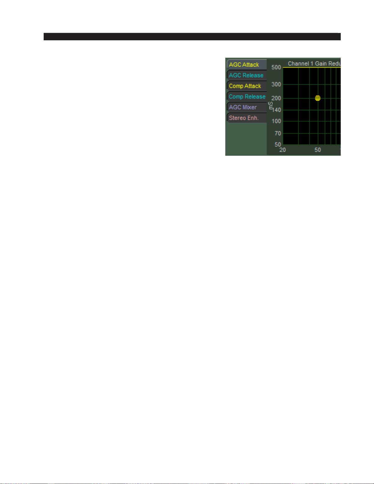
FM-531HD PRO GUI
AGC/Compressor Sidebar Menu
It should be noted rst that all processing bands
may be adjusted by rst selecting the desired control
type tab, and then using the blue dot navigation method
covered previously to adjust individual band parameters.
For more information on how to adjust these controls,
please see the “FM‑531HD Graphical Interface Opera‑
tion” section of this chapter.
AGC Attack
This control determines how quickly the AGC will
respond to changes in the audio. The range is 50ms to
500ms. 300ms is a recommended starting point.
AGC Release
This control determines the rate at which the AGC will increase gain. The range is
1 second to 7 seconds. 7 seconds is VERY slow and recommended for ne‑arts or clas‑
sical programming. 1 second is very fast (for an AGC) and is recommended only if a
certain sonic texture is desired. The recommended settings are between 2 and 5 seconds.
Compressor Attack
This control determines how quickly the Compressor will respond to audio not
caught by the AGC. The compressor deals with short term peaks. The recommended
setting for the compressor to sound “musical” is between 10 and 30ms. Compressor
settings faster than 10ms can make the audio sound constricted. Conversely, settings
slower than 30‑50ms can prove to be ineffective and can make the 31‑band limiter
work harder than it needs to.
Compressor Release
This control determines how quickly the compressor will return to the processing
“oor” established by the AGC. The ve band AGC/Compressor are tied together, with
the ve band AGC establishing the level of gain reduction and the compressor adding
additional compression to the AGC. The Compressor is never allowed to achieve more
gain than the AGC; that is, it will release to the AGC’s platform. The release time range
is 50ms to 1 second (1000ms). The best starting point is usually to set the release time
to the attack time of the AGC. Thus, if the AGC attack time is 300ms, the Compressor
release time should be 300ms. This is not a rule, just a good starting point if you are
building a preset from scratch.
AGC Mixer
The AGC Mixer is the output of the L+R content of the processed signal. Very dra‑
matic EQ changes can be made here, however, it is recommended that these controls
are set at and the parametric EQ is used for any EQ changes. If you nd you need
something in addition to the parametric EQ, these controls are here for your use.
Stereo Enhance
Stereo Enhance is the difference output of the processed signal. Here, you can add
stereo enhancement to specic parts of the audio spectrum without raising the overall
FM-531HD / May 2013
page 3 – 27
Page 91
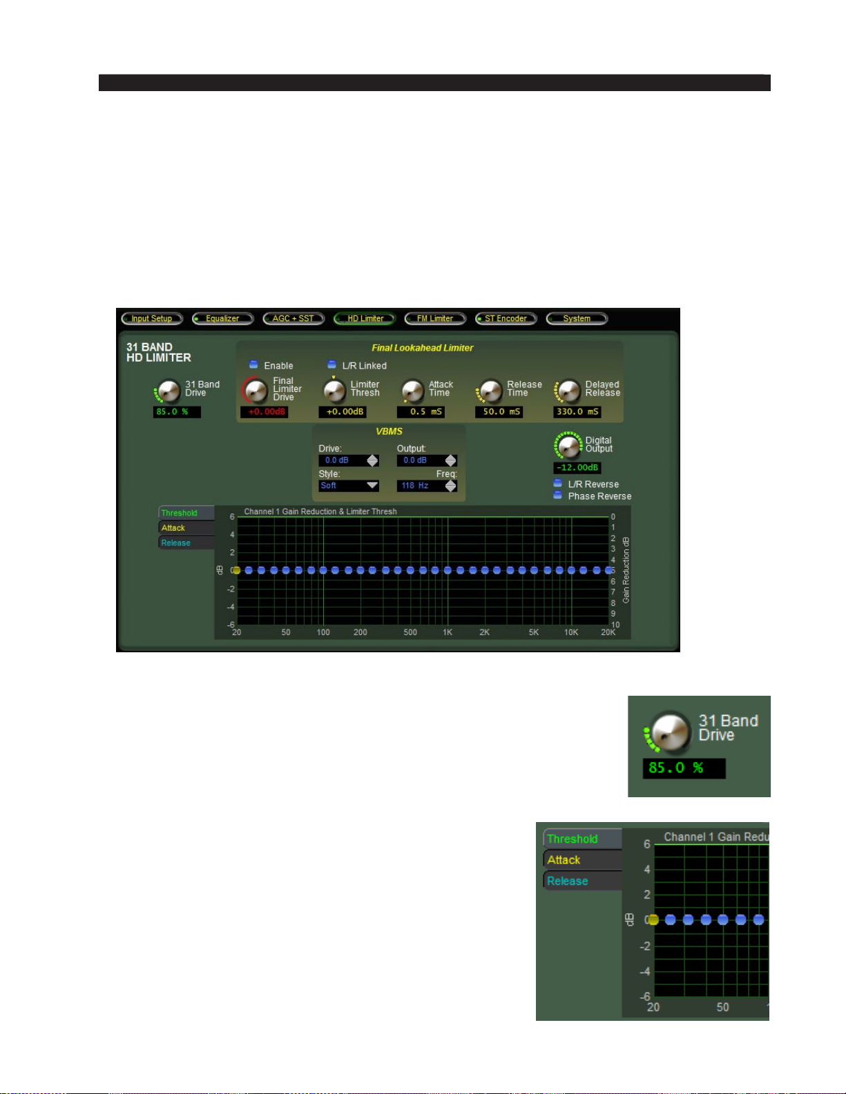
FM-531HD PRO GUI
L – R gain. This simple step allows you to tailor the audio so that stereo enhancement
will occur in bands most critical to the human ear without raising the L – R gain in
the entire spectrum, which adds little audible benet but can aggravate multipath. The
most dramatic changes will be heard in Bands 3 & 4. A good way to add some stereo
enhancement to the overall mix would be to raise Band 3 & 4 to between +2 and +3 dB.
HD LIMITER MENU
The 31 Band HD Limiter screen contains the controls necessary to ne tune the
sound of the HD output as well as adjust its peak control method.
31 Band Drive
The 31 Band Drive control determines the amount of input signal ap‑
plied to the 31‑band limiter – less drive creates a more gentle sound while
still controlling peaks. Higher settings make the sound more aggressive
by increasing short term density. Extremely high drive settings which
cause more than 5‑6dB of continuous gain reduction are unnecessary,
can become fatiguing, and may create a less than desirable operating
condition for a perceptual codec. Drive is adjustable from 80 to 100%.
31 Band Limiter Sidebar
Just like in the ve band AGC/Compressor, there is a
sidebar with some special adjustments available to the user
to tailor the sound of the 31‑band limiter. It should be noted
rst that all bands of audio processing can be adjusted as
a group or independently in the sidebar menus. For more
information on how to adjust these controls, please see the
“FM‑531HD Graphical Interface Operation” section of
this chapter.
FM-531HD / May 2013
page 3 – 28
Page 92
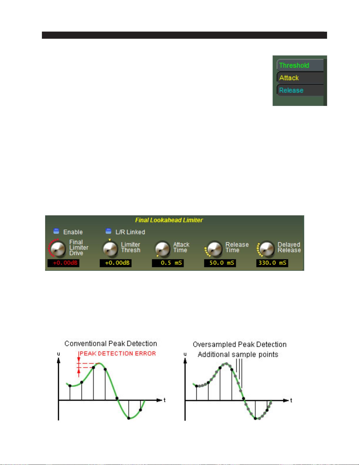
FM-531HD PRO GUI
Threshold
The Threshold control determines when limiting will start in a particu‑
lar band. The range for the FM‑531HD limiter threshold control can be
adjusted over a 12dB range to offset the 31‑band Limiter Drive.
Attack
This control determines how quickly the Limiter will respond to audio
once it exceeds the limiter threshold. Recommended settings are between 30 and 10ms
Release
The Release time determines how quickly the limiter will return to 0dB once audio
has fallen below the limiter threshold. Faster release times will yield a louder sound while
slower times will yield a smoother sound at the expense of loudness.
Because of the way the 31‑band limiter works, there is a lot of leeway with attack
and release times and these controls have been set so that the end user doesn’t drive the
car “off the cliff.” Basically, only extreme settings will yield a totally undesired sound.
That being said, these controls should also not be adjusted haphazardly.
Lookahead Limiter
The output of the 31‑band Limiter can be peak controlled by a special high‑speed
feed forward limiter with a 0.5 millisecond look ahead time. The control path, and not
the audio path, is oversampled in order to achieve extremely precise peak control. Be‑
cause the goal of oversampling is better peak control through ner denition of the audio
waveform, oversampling of the audio signal itself is not only unnecessary, but wastes
DSP resources. The graphic below visually illustrates why control signal oversampling
is more effective.
FM-531HD / May 2013
page 3 – 29
Page 93
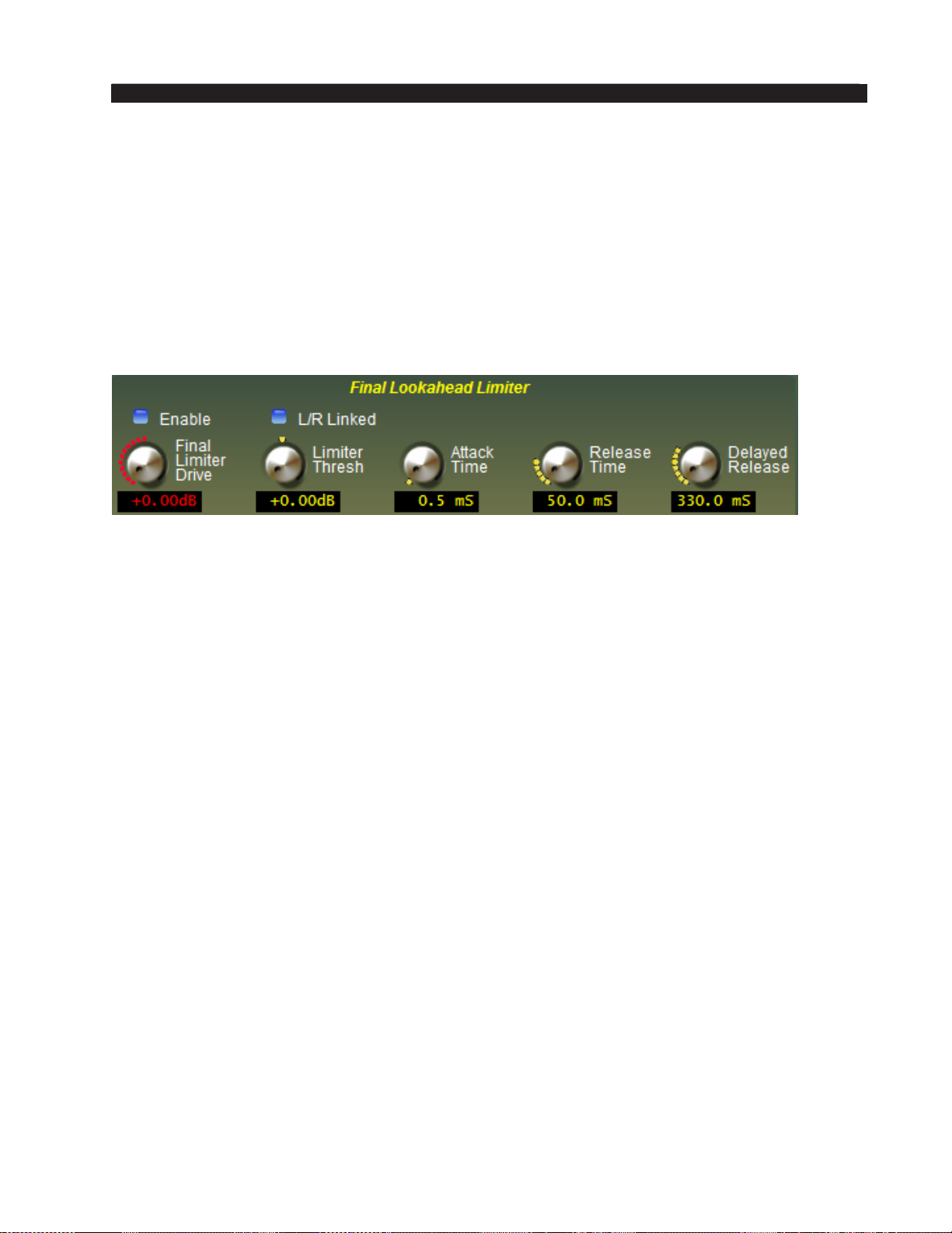
FM-531HD PRO GUI
In a conventional peak detector, audio excursions occurring between individual
samples are “missed,” and therefore the audio signal is “under read” during this instant.
This results in inaccurate peak control.
By increasing the sample rate of the detector to oversample the audio waveform
only at the detector it becomes possible to read the audio waveform with much higher
precision. This results in far more accurate peak control.
Note that it is not only unnecessary to oversample the main audio path, it is actually
undesirable; it would result in the same problem a conventional detector has because
the ratio of audio to detector sample rates would be the same as in the conventional
case. Additional DSP resources would have been used with no benet.
Limiter Enable
When the Enable check box is checked the look ahead limiter is enabled.
L/R Linked
When this box is checked the left and right channel control signals are common.
This prevents unnatural stereo image shifts when one channel needs to reduce the
signal to control peak excursions.
Final Limiter Drive
This control drives the output of the 31‑band limiter into the nal peak limiter.
Care should be taken to monitor the FINAL meter in the analysis display to view the
amount of gain reduction in the nal HD limiter. Too much gain reduction can cause
pumping.
Limiter Threshold
The Limiter Thresh control adjusts the relative threshold of the look ahead limiter
compared to the setting of the Final Limiter Drive control and is adjusted until the
onset of limiting is reached with normal program material as indicated by the gain
reduction bargraph. Adjustable over a +/‑ 6dB range.
Attack Time
The look ahead Limiter Attack Time control adjusts the attack time of the look ahead
limiter. Attack times from 0.2 milliseconds through 0.5 milliseconds allow the limiter
to “look ahead” in time and react to signal peaks before they arrive at the limiter’s
gain control algorithm. Attack time settings greater than 0.5 milliseconds and up to
the limit of 30 milliseconds allow the limiter to operate conventionally.
For example, if the attack time control is set to 1.0 milliseconds, the actual attack
time is 0.5 milliseconds. This is because the 0.5 millisecond look ahead is always in
FM-531HD / May 2013
page 3 – 30
Page 94
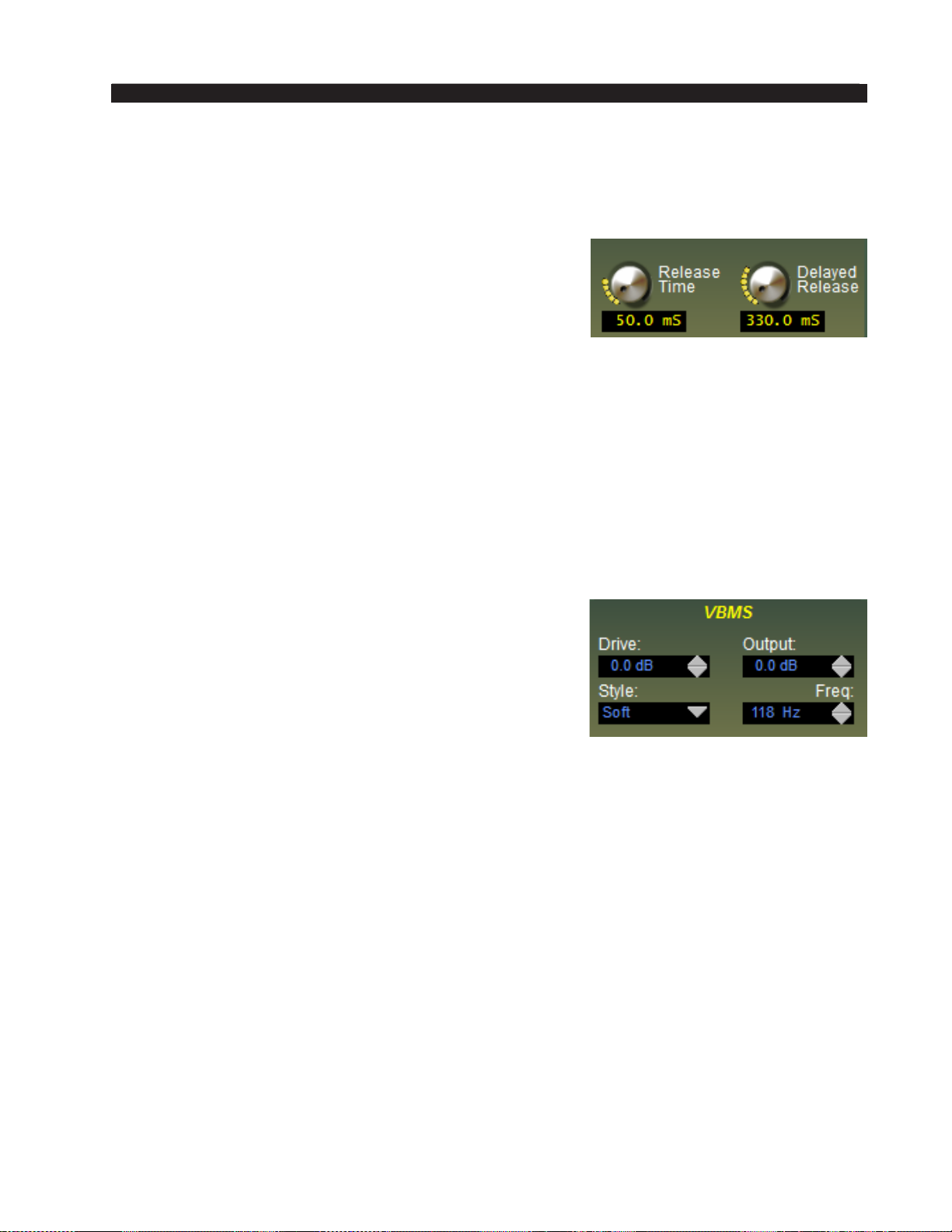
FM-531HD PRO GUI
circuit and its value must be subtracted from any adjustment of 0.5 milliseconds or greater
in order to know the actual attack time.
Release Time
The Release Time controls the primary (fast) release
time of the look ahead limiter. Slower settings (longer
release times) cause the peak limiter to recover more
slowly from limiting. Release times set too slow may
allow undesirable signal ducking to occur. Fast release
times increase signal density, and release times that are
too fast result in increased intermodulation distortion which can “muddy” the sound. The
control ranges from 33.0 to 330.0 milliseconds
Delayed Release
The Delayed Release controls the secondary (slow) release of the look ahead limiter.
Here, the limiter will release the rst 3dB of gain reduction at the (faster) Release setting,
and the remainder of the Release at the Delayed Release timing. This will drastically reduce
intermodulation distortion and allow more limiting depth without incurring a distortion
penalty. The control ranges from 100ms to 1.0 seconds.
VBMS (Vorsis Bass Management System)
The Vorsis Bass Management System allows extremely
low program frequencies to be processed without causing
dynamic gain changes and without generating undesir‑
able intermodulation artifacts. Its primary purpose is to
allow the thumps of kick drums and other percussion
instruments to sound natural in their “percussiveness.”
The algorithm operates in left/right mode treating both
channels identically.
Our laboratory research has revealed that it is perfectly acceptable to process very low
frequency material using the VBMS prior to HD exciters provided that the harmonics
caused by the VBMS are well controlled spectrally. Since our algorithm does not allow
signicant harmonic levels above the third or fth harmonic (depending on the Style set‑
ting) there is no audible downside to using the VBMS with coded audio. Furthermore, the
ability to utilize the VBMS on both the FM and HD sides of the processor allows the sound
to be more evenly matched as receiver‑based digital to analog crossfades are encountered.
Drive
This control adjusts the amount of drive to the VBMS algorithm and is adjustable over
a range of +/‑ 6dB.
Style
Two VBMS operating styles, plus Off, are available. The Hard setting has a transfer
function occupying approximately 1dB of transition amplitude. The waveform control is
fairly abrupt and generates a fair amount of harmonics; however, we eliminate everything
above the fth harmonic. The Soft setting operates with a transfer function occupying ap‑
proximately 2dB of transition amplitude. Therefore the control is less sharp than the hard
setting, generating even fewer harmonics.
FM-531HD / May 2013
page 3 – 31
Page 95
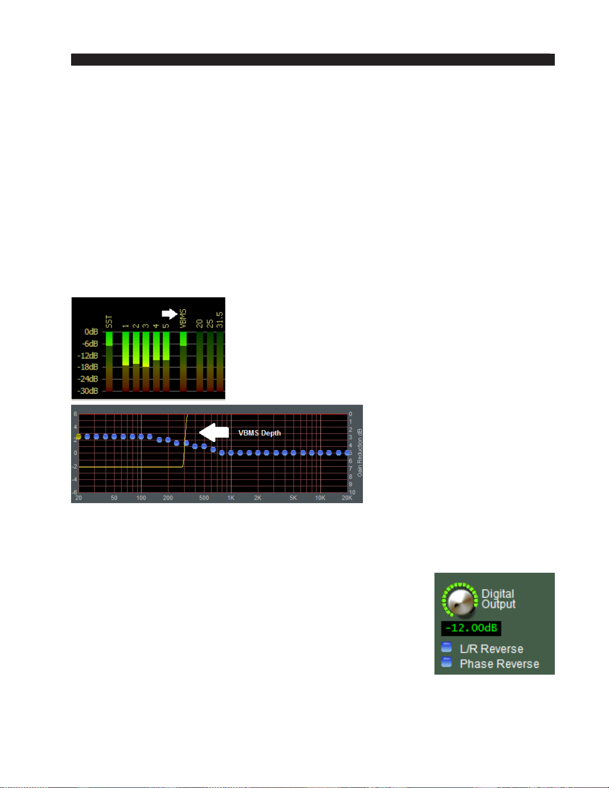
FM-531HD PRO GUI
While the two settings may appear to be almost the same, because the transition am‑
plitude is 1dB greater on the soft setting there is a signicant difference in how the two
VBMS transfer functions sound on actual program material.
Output
The VBMS Output control adjusts the output of the VBMS algorithm and can be
thought of as a “low bass mix” control. Settings higher than 0.0dB add more bass sound
to the overall mix, while settings lower than 0.0dB reduce the amount of bass. Both
the VBMS Drive and the VBMS Output controls may be generally adjusted to taste.
However, care should be exercised in the setting of the VBMS Output control because
settings above about +2dB may cause the amplitude of bass to reach the nal limiter and
added distortion may result. Like VBMS Drive, the VBMS Output is adjustable over a
range of +/‑ 6dB
VBMS Frequency
The VBMS Freq control tunes the VBMS algorithm’s
frequency of operation from 80Hz to 300Hz with the
program energy that is not passing through the algorithm
time aligned for coincidence regardless of the settings.
VBMS Metering
There are two ways to monitor the amount of process‑
ing being done by the VBMS.
VBMS can be seen on
the Analysis Screen on the
Pro GUI or in the Guru GUI.
VBMS can also been seen in
Pro GUI in the Limiter gain
reduction graph. Its activity is
indicated by the yellow line.
Depending on how hard the
VBMS is driven, one may or may not observe much activity on the VBMS metering. In
fact, only when a lot of bass is present in source material will VBMS show any activity
on the meters. This does not mean VBMS is not working or acting on the audio.
Digital Output
The Digital Output control adjusts the precise peak audio signal
level at the HD Limiter of the FM‑531HD. The resulting peak out‑
put levels in dBFS are indicated by the front panel and remote GUI
bargraph meters. This control can be set to OFF or adjusted over the
range of ‑79.95dBFS to 0.00dBFS.
FM-531HD / May 2013
page 3 – 32
Page 96
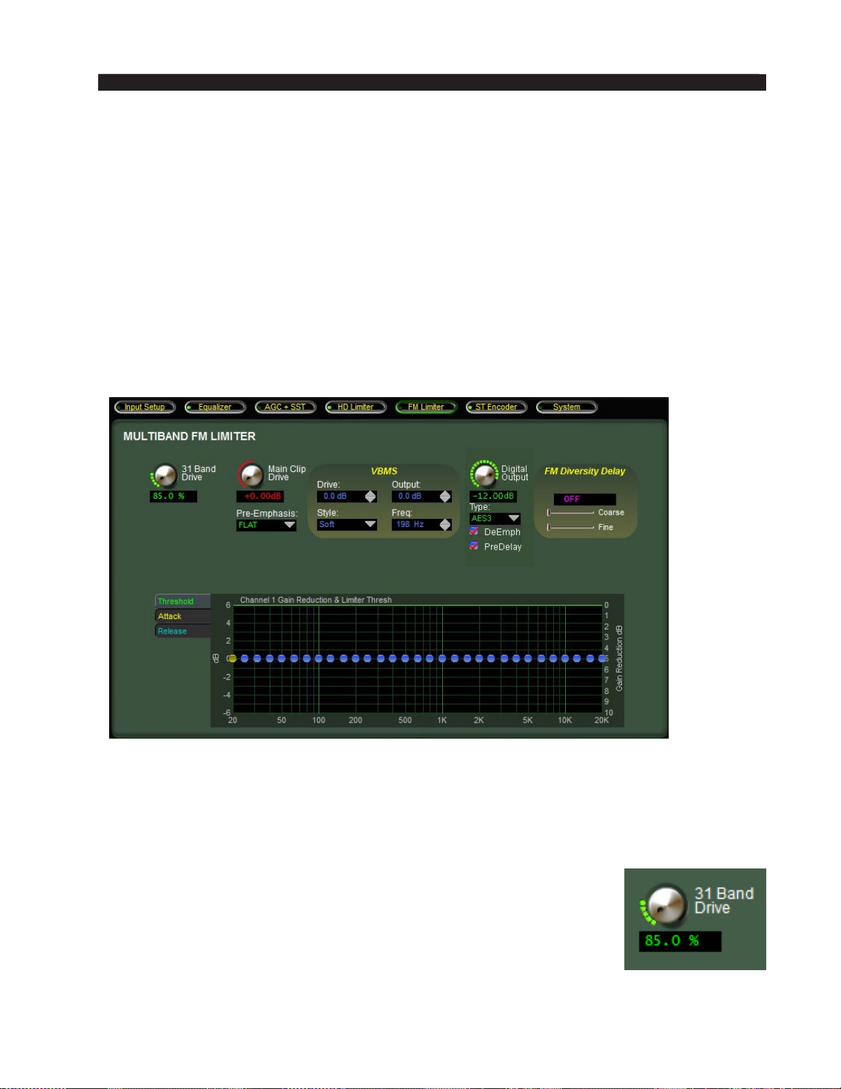
FM-531HD PRO GUI
L/R Reverse
The L/R Reverse ips left and right on the HD output to correct for any wiring
issues between the two channels. Phase reverse compensates for a known bug in certain software versions of older HD exciters.
Phase Reverse
Certain software versions within the iBiquity HD Radio system have an inadvertent signal polarity inversion putting the analog and digital signals 180 degrees out
of phase resulting in audible anging as the two signals crossfade in a listener’s HD
receiver. When the Phase Reverse check box is checked, it ips the polarity of the
HD Radio AES/EBU output signal by 180 degrees to compensate for this anomaly.
FM LIMITER MENU
The 31‑band FM Limiter screen contains the controls necessary for ne tuning the
sound of the FM output and adjusting its peak control method. These controls allow
the user to make many tradeoffs between loud and clean, in ways that have never been
available before in an FM peak limiter.
31 Band Drive
The 31 Band Drive control determines the amount of input signal
applied to the 31‑band limiter – less drive creates a more gentle sound
while still controlling peaks. Higher settings make the sound more
aggressive by increasing short term density. Extremely high drive settings which cause more than 5‑6 dB of continuous gain reduction are
unnecessary, can become fatiguing, and may create a less than desirable
operating condition for a perceptual codec. The 31 Band Drive control
is adjustable from 80 to 100%.
FM-531HD / May 2013
page 3 – 33
Page 97
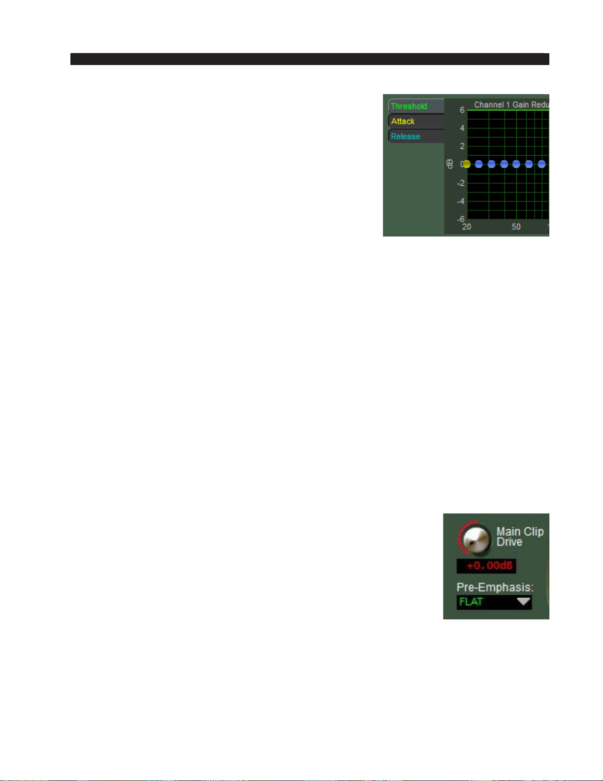
FM-531HD PRO GUI
31 Band FM Limiter Sidebar
Just like the ve band AGC/Compressor, there is a sidebar
with some special adjustments available to the user to tailor
the sound of the 31‑band limiter. It should be noted rst that
all bands of audio processing can be adjusted as a group or
independently in the sidebar menus. For more information
on how to adjust these controls, please see the “FM‑531HD
Graphical Interface Operation” section of this chapter.
Threshold
The Threshold control determines at what level limiting
will start in a particular band. The range for the FM‑531HD
limiter threshold controls is adjustable over a 12dB range and they work in concert with
the 31‑band Limiter Drive to set the individual band’s operating behavior.
Attack
The Attack control determines how quickly the limiter will respond to audio once it
exceeds the limiter threshold. Recommended attack time settings are between 30 and
10ms. Longer attack times are possible for frequencies below the VBMS frequency
setting. Overall, longer attack times will cause the look ahead limiter to work harder
and/or overshoot.
Release
The Release control determines how quickly the limiter will return to 0dB once audio
has fallen below the limiter threshold. Faster release times will yield a louder sound
while slower times will yield a smoother sound at the expense of loudness.
Because of the way the 31‑band limiter works, there is a lot of leeway with attack
and release times and these controls have been set so that the end user doesn’t drive the
car “off the cliff.” Basically, only extreme settings will yield a totally undesired sound.
That being said, these controls should also not be adjusted haphazardly.
Main Clip Drive
The Main Clip Drive controls the absolute peak output level of the
31‑band section and is adjustable +/‑6dB. The resolution of this control
is 0.05dB, ne enough for the most exacting output level adjustments.
Pre-Emphasis
FM Pre-Emphasis is selectable as 50 or 75 microseconds, or Flat
(OFF).
FM-531HD / May 2013
page 3 – 34
Page 98
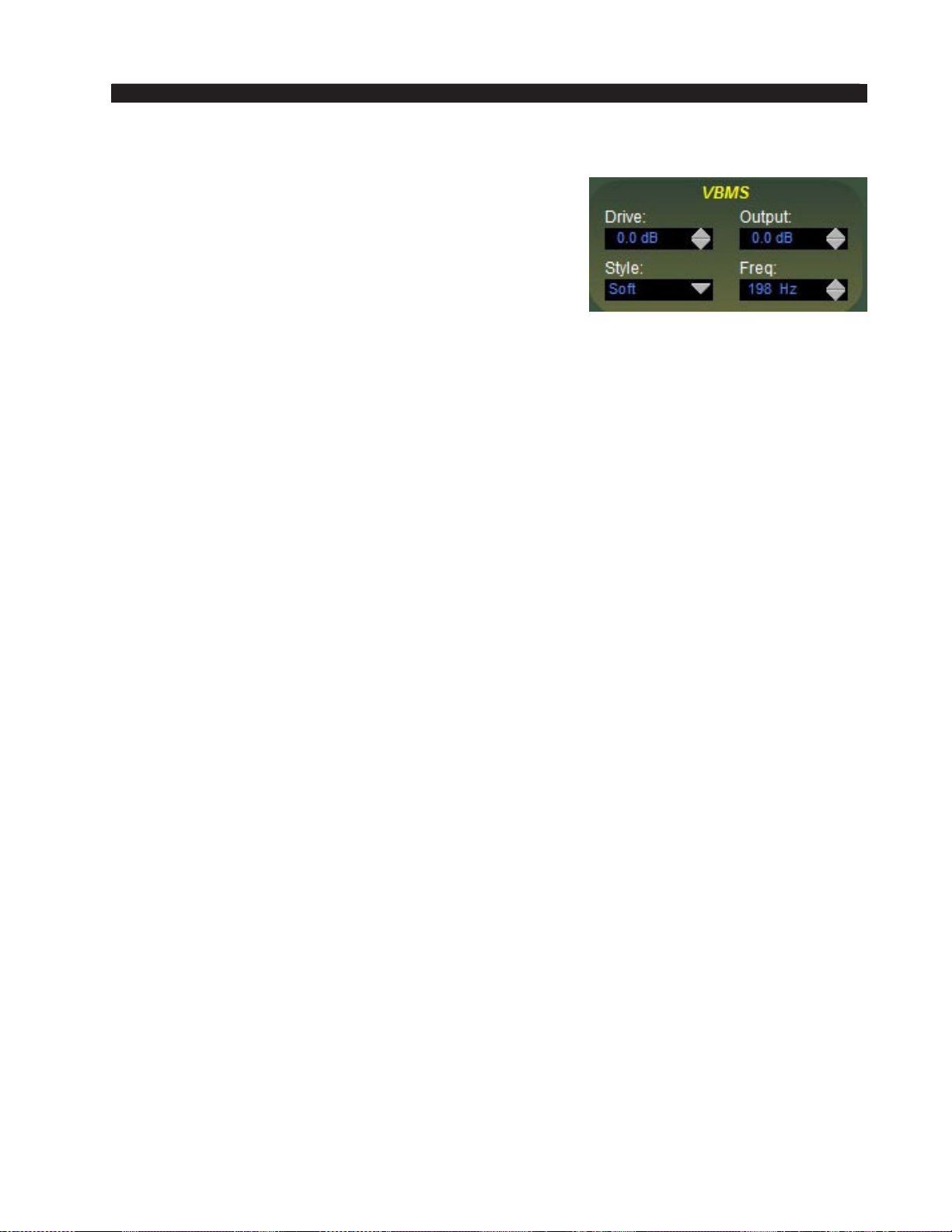
FM-531HD PRO GUI
VBMS (Vorsis Bass Management System)
The Vorsis Bass Management System allows extremely
low program frequencies to be processed without causing
dynamic gain changes and without generating undesir‑
able intermodulation artifacts. Its primary purpose is to
allow the thumps of kick drums and other percussion
instruments to sound natural in their “percussiveness.”
The algorithm operates in left/right mode treating both
channels identically.
Our laboratory research has revealed that it is perfectly acceptable to process very
low frequency material using the VBMS prior to all modern FM exciters provided that
the harmonics caused by the VBMS are well controlled spectrally. Since our algorithm
does not allow signicant harmonic levels above the third or fth harmonic (depending
on the Style setting) there is no audible downside to using the VBMS with coded audio.
Furthermore, the ability to utilize the VBMS on both the FM and HD sides of the pro‑
cessor allows the sound to be more evenly matched as receiver‑based digital to analog
crossfades are encountered.
Drive
This control adjusts the amount of drive to the VBMS algorithm and is adjustable
over a range of +/‑ 6dB.
Style
Two VBMS operating styles, plus Off, are available. The Hard setting has a transfer
function occupying approximately 1dB of transition amplitude. The waveform control is
fairly abrupt and generates a fair amount of low order harmonics; however, we eliminate
everything above the fth harmonic. The Soft setting operates with a transfer function
occupying approximately 2dB of transition amplitude. Therefore the control is less sharp
than the hard setting, generating even fewer harmonics.
While the two settings may appear to be almost the same, because the transition am‑
plitude is 1dB greater on the soft setting there is a signicant difference in how the two
VBMS transfer functions sound on actual program material.
Output
The VBMS Output control adjusts the output of the VBMS algorithm and can be thought
of as a “low bass mix” control. Settings higher than 0.0dB add more bass sound to the
overall mix, while settings lower than 0.0dB reduce the amount of bass. Both the VBMS
Drive and the VBMS Output controls may be generally adjusted to taste. However, care
should be exercised in the setting of the VBMS Output control because settings above
about +3dB may cause the amplitude of bass to reach the master clipper and added distor‑
tion may result. Like VBMS Drive, VBMS Output is adjustable over a range of +/‑ 6dB.
VBMS Frequency
The VBMS Freq control tunes the VBMS algorithm’s frequency of operation from
60Hz to 300Hz with the program energy that is not passing through the algorithm time
aligned for coincidence regardless of the settings.
FM-531HD / May 2013
page 3 – 35
Page 99
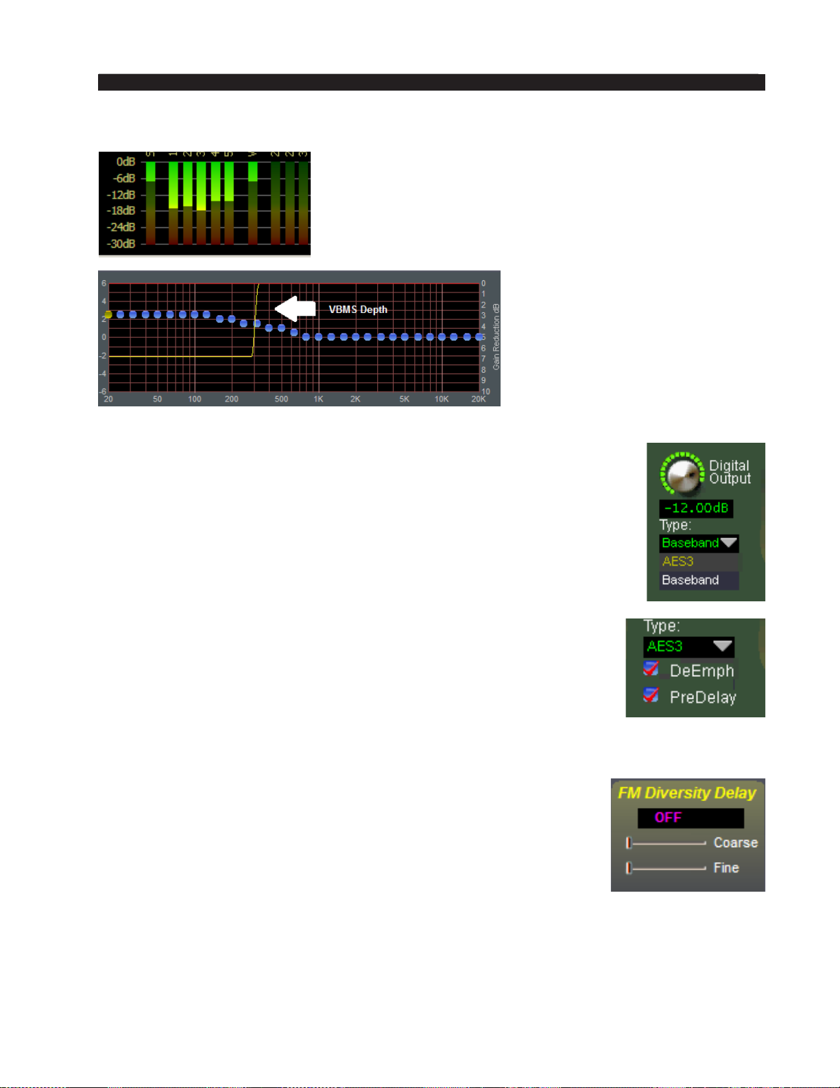
FM-531HD PRO GUI
VBMS Metering
There are two ways to monitor the amount of process‑
ing being done by the VBMS.
VBMS can be seen on the Analysis Screen on the PRO
GUI or in the Guru GUI. VBMS can also been seen in
PRO GUI in the Limiter gain reduction graph. Its activity
is indicated by the yellow line.
Depending on how hard
the VBMS is driven, one may
or may not see much activity
with VBMS. In fact, only when
a lot of bass is present in source
material will VBMS show any
activity on the meters. This
does not mean VBMS is not
working or acting on the audio.
Digital Output
The Digital Output control adjusts the precise peak audio signal level
at the FM Limiter of the FM‑531HD. The resulting peak output levels in
dBFS are indicated by the front panel and remote GUI bargraph meters.
This control can be set to OFF or adjusted over the range of ‑79.95dBFS
to 0.00dBFS.
Digital output available as AES3 digital signal or baseband192 digital
multiplex signal.
AES3 Digital
DeEmph – When checked, this option applies de‑emphasis to the
FM digital outputs. The type of de‑emphasis is determined by the pre‑
emphasis selected. If no pre‑emphasis is selected, this button is defeated.
PreDelay – When checked, the digital FM output will always be fed before the diversity delay.
FM Diversity Delay
The FM‑531HD contains an internal digital delay to compensate
for the corresponding delay in the HD Radio codec. The delay sec‑
tion is capable of providing up to ten seconds of compensating delay
insteps of 100 microseconds.
The Coarse delay is set rst to align the analog and HD signals as
closely as possible, and then the Fine delay control is used to trim the
delay to precisely compensate for that in the HD channel. Generally it
is a good idea to set the Fine delay to midrange before adjusting Coarse delay. Resolu‑
tion of the Coarse delay is 50 milliseconds.
The Fine control covers a range of 50 milliseconds in 0.1 millisecond (100 microsec‑
ond) steps. If the Fine control does not set the increment exactly to where it is desired,
double clicking on the delay value text box will open it for manual entry of the delay time.
FM-531HD / May 2013
page 3 – 36
Page 100
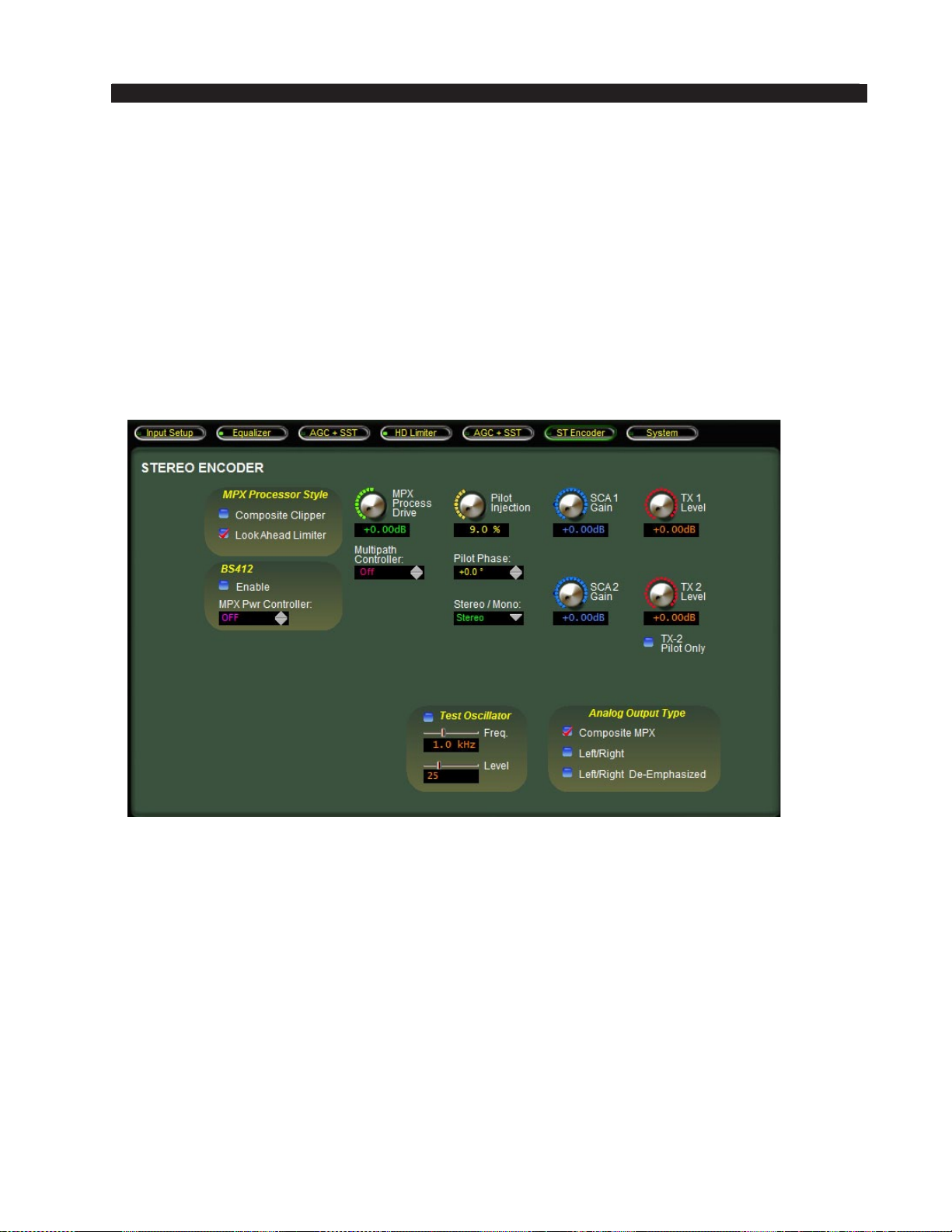
FM-531HD PRO GUI
When the Delay controls are both set to their minimum settings, “OFF” appears in
the delay window to signal that there is no delay at all in the circuit.
Entering Delay Values
You can double click on the delay value window to directly enter a numeric delay
value in milliseconds. This is useful when you know roughly how much delay is re‑
quired or wish to try various values quickly. You may also hold down the Shift key on
your keyboard while adjusting a delay slider to effect faster adjustment rates, or hold
down the Ctrl key to achieve ner control.
STEREO ENCODER MENU
The Stereo Encoder screen contains the controls required to congure the FM‑531HD’s
internal DSP‑based precision stereo generator.
MPX Processor Style
The FM‑531HD is provides two separate ways to process the composite stereo
waveform:
Composite Clipper
Uses a high ratio transfer function clipper to precisely control peaks without gen‑
erating very high order distortion. This clipper has a brighter sound than the look
ahead limiter and also creates more high order harmonic artifacts. Note that we do not
mathematically remove the higher order odd harmonics in this clipper algorithm like
we do in the VBMS section because those harmonics are required in order to make the
waveform have a more tightly dened peak amplitude.
FM-531HD / May 2013
page 3 – 37
 Loading...