

Page 1

Bridge 2001
Digital Audio
Network Router
Technical
Manual
Wheatstone Corporation
July 2001
Page 2

Bridge 2001 Digital Audio Network RouterBridge 2001 Digital Audio Network Router
Bridge 2001 Digital Audio Network Router
Bridge 2001 Digital Audio Network RouterBridge 2001 Digital Audio Network Router
©2001 Wheatstone Corporation
600 Industrial Drive
New Bern, North Carolina 28562
tel 252-638-7000 / fax 252-637-1285
Page 3
Attention!
FF
ederal Communications Commission (FCC)ederal Communications Commission (FCC)
F
ederal Communications Commission (FCC)
FF
ederal Communications Commission (FCC)ederal Communications Commission (FCC)
Compliance Notice:Compliance Notice:
Compliance Notice:
Compliance Notice:Compliance Notice:
Radio FRadio F
Radio F
Radio FRadio F
NOTE:NOTE:
NOTE: This equipment has been tested and found to comply with the
NOTE:NOTE:
limits for a Class A digital device, pursuant to Part 15 of the FCC rules. These
limits are designed to provide reasonable protection against harmful
interference when the equipment is operated in a commercial environment.
This equipment, generates, uses and can radiate radio frequency energy
and, if not installed and used in accordance with the instruction manual,
may cause harmful interference to radio communications. Operation of this
equipment in a residential area is likely to cause harmful interference in
which case the user will be required to correct the interference at his own
expense.
requency Noticerequency Notice
requency Notice
requency Noticerequency Notice
AA
TTENTIONTTENTION
A
TTENTION
TTENTIONTTENTION
AA
This is Class A product. In a domestic environment,This is Class A product. In a domestic environment,
This is Class A product. In a domestic environment,
This is Class A product. In a domestic environment,This is Class A product. In a domestic environment,
this product may cause radio interference, in which case,this product may cause radio interference, in which case,
this product may cause radio interference, in which case,
!
This equipment must be installed and wired properly in order to assure
compliance with FCC regulations.
Caution!Caution!
Caution!
Caution!Caution!
Wheatstone Corporation could void the user's authority to operateWheatstone Corporation could void the user's authority to operate
Wheatstone Corporation could void the user's authority to operate
Wheatstone Corporation could void the user's authority to operateWheatstone Corporation could void the user's authority to operate
this equipment.this equipment.
this equipment.
this equipment.this equipment.
this product may cause radio interference, in which case,this product may cause radio interference, in which case,
the user may be required to take appropriate measures.the user may be required to take appropriate measures.
the user may be required to take appropriate measures.
the user may be required to take appropriate measures.the user may be required to take appropriate measures.
Any modifications not expressly approved in writing by Any modifications not expressly approved in writing by
Any modifications not expressly approved in writing by
Any modifications not expressly approved in writing by Any modifications not expressly approved in writing by
2001 / Jul 2001
RR
R
RR
EADEAD
EAD
EADEAD
M M
M
M M
!!
EE
E
!
EE
!!
Page 4
CONTENTS
Bridge 2001
T echnical Manual
Table of Contents
Chapter 1 – General Information
Introduction ................................................................................ 1-2
Power Supply ............................................................................. 1-3
Power Supply Cable Pinout.................................................................................... 1-3
Failsafe Dual Redundant Supply............................................................................ 1-4
Energizing ............................................................................................................... 1-4
I/O Connections.......................................................................... 1-5
The Insulation Displacement Connector System ...................................................1-5
Digital Audio Connections ...................................................................................... 1-6
Unbalanced Analog Connections ........................................................................... 1-6
Unbalanced Digital Connections (SPDIF) ..............................................................1-7
Chapter 2 - Hardware
Chassis/Backplane Overview ................................................... 2-4
Chassis Configuration Guidelines ........................................... 2-5
Audio Slots.............................................................................................................. 2-5
Reserved Slots ....................................................................................................... 2-5
Backplane Termination.............................................................. 2-5
Digital Input Card (AES-2024)
Overview ..................................................................................... 2-6
AES Input Interface .................................................................... 2-6
Internal Programming Options ................................................. 2-6
Status LED’s ............................................................................... 2-7
Hook-Ups
DB-25 - Digital Audio Connections......................................................................... 2-8
2DB-25 - Digital Audio Connections....................................................................... 2-8
8 BNC - Digital Audio Connections ...................................................................... 2-10
8 RJ-45 - Digital Audio Connections .................................................................... 2-10
DB Panel Pinout Drawing ........................................................ 2-12
2DB Panel Pinout Drawing .................................................... 2-12a
8 BNC Panel Pinout Drawing ................................................ 2-12b
8 RJ Panel Pinout Drawing.................................................... 2-12c
2001 / Jul 2001
2001 / Aug 03
2001 / Oct 03
page Contents – 1
Page 5

CONTENTS
Analog Input Card (ADI-2001)
Overview ................................................................................... 2-13
Analog Input Interface ............................................................. 2-13
Internal Programming Options ............................................... 2-13
Status LED’s ............................................................................. 2-14
Hook-Ups
Upper DB-25 - Analog Audio Connections........................................................... 2-15
Lower DB-25 - Analog Audio Connections........................................................... 2-15
8 RJ-45 - Analog Audio Connections ...................................................................2-16
2DB Panel Pinout Drawing ...................................................... 2-17
8 RJ Panel Pinout Drawing...................................................... 2-18
Digital Output Card (DO-2001)
Overview ................................................................................... 2-19
AES Output Interface ............................................................... 2-19
AES Channel Status Implementation ..................................... 2-19
Internal Programming Options ............................................... 2-20
Status LED’s ............................................................................. 2-21
Hook-Ups
DB-25 - Digital Audio Connections....................................................................... 2-22
8 BNC - Digital Audio Connections ...................................................................... 2-22
8 RJ-45 - Digital Audio Connections .................................................................... 2-23
DB Panel Pinout Drawing ........................................................ 2-24
8 BNC Panel Pinout Drawing .................................................. 2-25
8 RJ Panel Pinout Drawing...................................................... 2-26
Analog Output Card (AO-2001)
Overview ................................................................................... 2-27
Analog Output Interface .......................................................... 2-27
Internal Programming Options ............................................... 2-27
Status LED’s ............................................................................. 2-28
Hook-Ups
Upper DB-25 - Analog Audio Connections........................................................... 2-29
Lower DB-25 - Analog Audio Connections........................................................... 2-29
8 RJ-45 - Analog Audio Connections ...................................................................2-30
2DB Panel Pinout Drawing ...................................................... 2-31
8 RJ Panel Pinout Drawing...................................................... 2-32
Host CPU (CPU-2001)
Overview ................................................................................... 2-33
Multi CPU/Failover CPU Systems ........................................... 2-33
CPU-2001 BIOS Settings/Format ............................................ 2-33
2001 / Jul 2001
page Contents – 2
Page 6

CONTENTS
Ethernet IP Addressing ........................................................... 2-34
Ethernet Interface Wiring ........................................................ 2-34
Internal Programming Options ............................................... 2-34
Switch Settings ........................................................................ 2-35
DIPSW1-SW4 - 485 Termination..........................................................................2-35
SW5 - CPU Reset................................................................................................. 2-35
DIPSW6 - Utility Switches .................................................................................... 2-35
DIPSW7 - Rack ID ................................................................................................ 2-35
DIPSW8 pos.1 - Autodetect..................................................................................2-35
SW9 - Master Select............................................................................................. 2-36
Jumper Settings ....................................................................... 2-36
J1 - RS-232 GND..................................................................................................2-36
J4 - AGND to DGND............................................................................................. 2-36
J5 - FPGA PGM.................................................................................................... 2-36
J6 - 48 or 44.1 kHz Sample Rate Select ..............................................................2-36
Serial Interface Ports ............................................................... 2-36
Status LED’s ............................................................................. 2-37
Hook-Ups
Left “A” DB-9 - Serial Interface Port1 Connections .............................................. 2-38
Right “B” DB-9 - Serial Interface Port 2 Connections...........................................2-38
RJ-45 - Ethernet Connections ..............................................................................2-38
Typical Ethernet Cable ............................................................ 2-39
Typical Crossover Cable ......................................................... 2-39
PWIH Panel Pinout Drawing.................................................... 2-40
Audio Network Card (OAN-2001)
Overview ................................................................................... 2-41
Internal Programming Options ............................................... 2-42
Switch Settings ........................................................................ 2-42
DIPSW1-SW4 - 485 Termination..........................................................................2-42
DIPSW5 position Local/Remote (Clock Sources) ................................................2-43
DIPSW5 position Secondary/Primary...................................................................2-43
DIPSW5 position 48 kHz / 44.1 kHz..................................................................... 2-43
DIPSW5 position Fiber/CAT5 ............................................................................... 2-43
SW6 - Reset..........................................................................................................2-43
DIPSW7 - Rack ID ................................................................................................ 2-44
?
?
Jumper Settings ....................................................................... 2-44
J1 - Ethernet Mode Setting................................................................................... 2-44
J2 - Reset..............................................................................................................2-44
J3, J5 - Clock Selection ........................................................................................ 2-45
Status LED’s ............................................................................. 2-46
Hook-Ups
Upper “A” DB-9 - Serial Interface Port1 Connections ..........................................2-47
Lower “B” DB-9 - Serial Interface Port 2 Connections .........................................2-47
RJ-45 - Ethernet Connections ..............................................................................2-47
CAT5 Crossover Cable for OAN to OAN Connections ......... 2-47
2001 / Jul 2001
2001 / Apr 03
page Contents – 3
Page 7

CONTENTS
Optical Fiber Interface ............................................................. 2-48
Connector Type ....................................................................................................2-48
Optical Fiber ......................................................................................................... 2-48
ONI Panel Pinout Drawing....................................................... 2-49
Stacking Card (CEX-2001)
Overview ................................................................................... 2-50
Configuring the Virtual Chassis ............................................. 2-50
TDM Assignment .................................................................................................. 2-50
CEX-2001 Rack ID ............................................................................................... 2-51
CEX-2001 Configuration Rules ............................................................................ 2-51
Internal Programming Options ............................................... 2-51
Switch Settings ........................................................................ 2-51
DIPSW1-not used ................................................................................................. 2-51
SW2 - Reset..........................................................................................................2-51
DIPSW3 - TDM Assign/Rack ID ...........................................................................2-51
Jumper Settings ....................................................................... 2-52
J1 - Crystal Select.................................................................................................2-52
J2 - Reset..............................................................................................................2-52
Status LED’s ............................................................................. 2-53
Hook-Ups .................................................................................. 2-54
Logic I/O Card (LIO-2001)
Overview ................................................................................... 2-55
Input Ports ................................................................................ 2-55
Output Ports ............................................................................. 2-56
Typical Input/Output Circuit.................................................... 2-56
Software Programming............................................................ 2-57
Internal Programming Options ............................................... 2-57
Jumper/Dipswitch Settings ..................................................... 2-57
Status LED’s ............................................................................. 2-58
Hook-Ups .................................................................................. 2-59
Upper “A” DB-25 - Logic In Ports Connections ....................................................2-59
Lower “B” DB-25 - Logic Out Ports Connections ................................................. 2-59
LIO Panel Pinout Drawing ....................................................... 2-61
Quad Audio Network Card (QAT-2001)
Overview ................................................................................... 2-62
Internal Programming Options ............................................... 2-64
Switch Settings ........................................................................ 2-64
DIPSW1, SW2, SW4 & SW5 - 485 Termination .................................................. 2-64
DIPSW7 - Fiber/CAT5 Ports A-B-C-D .................................................................. 2-65
DIPSW8 - Primary/Secondary Ports A-B-C-D...................................................... 2-65
DIPSW9 - Local/Remote (Clock Source) Ports A-B-C-D ..................................... 2-65
DIPSW10 - Audio/Console (Port Type) Ports A-B-C-D........................................ 2-65
2001 / Jul 2001
2001 / Sep 03
page Contents – 4
Page 8

CONTENTS
SW3 - Reset............................................................................................................. 2-65
DIPSW6 - Rack ID ................................................................................................... 2-66
Jumper Settings ...........................................................................2-66
J1 - Factory Use Only - Reset ................................................................................. 2-66
J2 - Factory Use Only - Watchdog Disable ............................................................. 2-66
J3 - Sample Rate Select - 48kHz/44.1kHz .............................................................. 2-66
Status LED’s .................................................................................2-67
Hook-Ups
Upper “A” DB-9 - Serial Interface Port1 Connections ............................................. 2-69
Lower “B” DB-9 - Serial Interface Port 2 Connections ............................................ 2-69
“A”, “B”, “C”, “D” RJ-45 - CAT5 Audio Network Connections .................................. 2-69
CAT5 Crossover Cable for QAT to QAT Connections ..............2-69
QCT Panel Pinout Drawing..........................................................2-70
QOT Panel Pinout Drawing .........................................................2-71
Digital Signal Processor Card (DSP-2001)
Overview .......................................................................................2-72
Internal Programming Options ...................................................2-72
Switch Settings ............................................................................2-73
SW1 - DSP Reset Switch ........................................................................................ 2-73
Jumper Settings ...........................................................................2-73
J1 - Factory Use Only - Watchdog Reset................................................................ 2-73
J2 - Factory Use Only - Watchdog Reset................................................................ 2-73
J3 - Factory Use Only - Watchdog Disable ............................................................. 2-73
Status LED’s .................................................................................2-74
Microphone Card (MIC-2001)
Overview .......................................................................................2-75
Analog Input Interface .................................................................2-75
Internal Programming Options ...................................................2-75
Status LED’s .................................................................................2-76
Hook-Ups
Upper DB-25 - Analog Audio Input Connections..................................................... 2-77
Lower DB-25 - Analog Audio Output Connections.................................................. 2-77
8 RJ-45 - Analog Audio Connections ...................................................................... 2-78
2DB Panel Pinout Drawing ..........................................................2-79
8 RJ Panel Pinout Drawing..........................................................2-80
2001 / Jul 2001
2001 / Oct 03
page Contents – 5
Page 9
CONTENTS
Chapter 3 - Controller Devices
XP Configuration GUI ...................................................................3-2
XY Controller GUI..........................................................................3-3
XY Rack Controller........................................................................3-3
Wheatstone Console XY Controller.............................................3-4
XY Controller Settings ..................................................................3-4
Setting an XY Controller Termination....................................................................... 3-4
Setting an XY Controller Address............................................................................. 3-4
XY Controller Signal Visibility......................................................3-5
XY Controller RS-485 Connections .............................................3-5
Overview ................................................................................................................... 3-5
Serial Port Options.................................................................................................... 3-6
Cable Wiring ............................................................................................................. 3-6
Typical RS-485 Cable Specifications ..........................................3-6
XY Controller RS-485 Cable Pinouts ...........................................3-6
Wheatstone Console Interface.....................................................3-7
Wheatstone Console RS-485 Connections.................................3-7
Console RS-485 Cable Pinouts....................................................3-7
Console CPU Module Settings.....................................................3-8
Console Address ...................................................................................................... 3-8
RS-485 Select / Termination .................................................................................... 3-8
Chapter 4 - XPoint Software Setup Guide
Bridge 2001 Ethernet/IP Address Quick Start ...........................4-2a
Ethernet Cabling ...................................................................................................... 4-2a
Default IP Address................................................................................................... 4-2a
Changing your PC’s IP Address .............................................................................. 4-2a
Changing the Bridge 2001’s IP Address ................................................................. 4-2a
Configuring IP Address in X-Point Software ........................................................... 4-2b
Saving the Bridge 2001 Configuration..................................................................... 4-2b
Getting Started ..............................................................................4-2
GUI Log-In......................................................................................4-2
Passwords ................................................................................................................ 4-2
Connection Between the Configuration GUI and Master Rack.4-3
System Configuration Menus ......................................................4-6
Tier Configuration ..................................................................................................... 4-6
Rack Configuration ................................................................................................... 4-7
Adding a Card to a Rack .......................................................................................... 4-7
Card/Signal Definition............................................................................................... 4-8
Audio Network Card Definition .............................................................................. 4-8
CPU Card Definition .............................................................................................. 4-9
Output Card Definition ........................................................................................... 4-9
2001 / Jul 2001
2001 / Oct 03
page Contents – 6
Page 10

CONTENTS
Input Card Definition.......................................................................................... 4-10
Viewing Defined Source & Destination Signals ................................................ 4-10
Configuration Rules and Recommendations........................................................ 4-11
Completing the Configuration ............................................................................... 4-11
Saving Your Configuration.................................................................................4-11
Config.txt File..................................................................................................... 4-11
Signal Definition....................................................................... 4-14
Configuring Logic I/O .............................................................. 4-15
Overview ............................................................................................................... 4-15
Routable Logic................................................................................................... 4-15
Trigger Port Logic .............................................................................................. 4-15
Routable Logic Signal Definitions.........................................................................4-16
Defining Routable Logic Functions.......................................................................4-17
Viewing Defined Logic Signals .............................................................................4-17
Configuring Triggered Port Logic ......................................................................... 4-18
Signal Locking.......................................................................... 4-19
Salvo Definition ........................................................................ 4-20
XY Rack or Console XY Controller Configuration ................ 4-21
Console Configuration ............................................................ 4-22
Special Functions - Console Locks ......................................................................4-22
Console Presets ................................................................................................... 4-22
XY GUI Controller Configuration ............................................ 4-23
Main Menu Summary ............................................................... 4-24
Glossary
Terminology............................................................................... G-1
Appendices
Appendix 1
Configuring the 2001 Switch Network Parameters .................A-3
Appendix 2
Failover CPU Configuration /Operation ...................................A-6
Appendix 3
Replacement Parts List .............................................................A-9
2001 / Jul 2001
2001 / Oct 03
page Contents – 7
Page 11

GENERAL INFORMATION
General Information
Chapter Contents
Introduction ................................................................................ 1-2
Power Supply ............................................................................. 1-3
Power Supply Cable Pinout.................................................................................... 1-3
Failsafe Dual Redundant Supply............................................................................ 1-4
Energizing ............................................................................................................... 1-4
I/O Connections.......................................................................... 1-5
The Insulation Displacement Connector System ...................................................1-5
Digital Audio Connections ...................................................................................... 1-6
Unbalanced Analog Connections ........................................................................... 1-6
Unbalanced Digital Connections (SPDIF) ..............................................................1-7
2001 / Jul 01
2001 / Aug 03
page 1 – 1
Page 12
GENERAL INFORMATION
General Information
Introduction
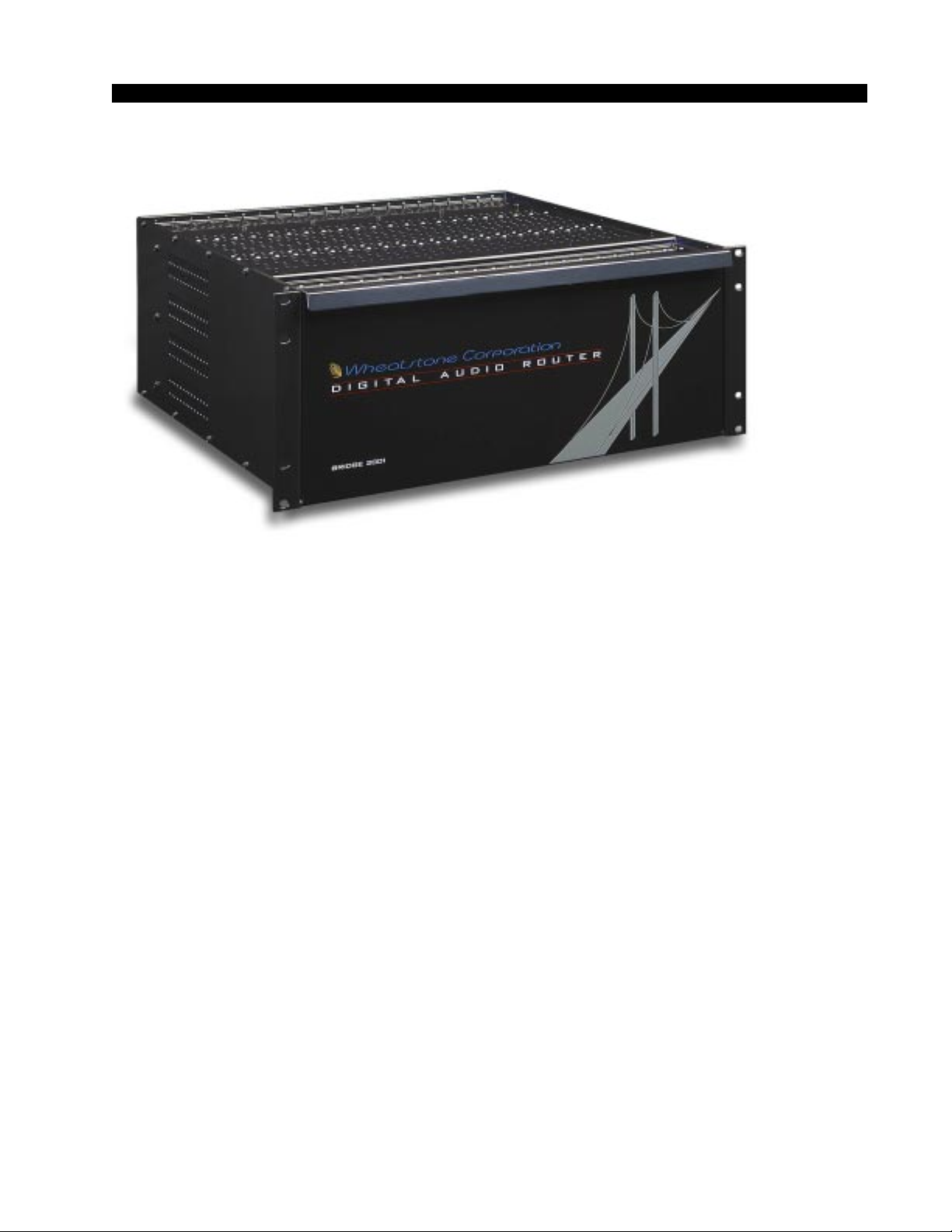
The Bridge 2001 Digital Audio Network Router rackmount unit occu-
pies four 19” wide rack (total height 7”) with 16” depth.
The 2001 is a unit that can take up to 512 discrete analog and digital audio
inputs in Audio Engineering Society (AES) format, and switch them to any
of 512 separate outputs. The unit’s backplane carries these signals via 32
16xTDM busses. Various input sources place the AES signals onto the
TDM busses, while output cards can select any combination of signals to
take off the TDMs to drive their output channels.
Systems can start small with a single cage and only a few cards; chassis
can be stacked to form a larger central system. Cages can be separated by
very long distances with many studios connected to your central rack room,
providing shared resources yet still permitting independently functioning
satellite studios, each with its own combination of analog and digital input
and output cards and connector modules specifically selected to suit a large
variety of gear. Individual 2001 switches may be connected together to form
a “Multi-Tiered” switch. This switch is arranged in a star topology, with a
central Hub switch connected to up to 14 satellite switches. This system
allows as many as 7168 channels of data comprising a maximum of 2048
input signals and 2048 outputs to be switched.
2001 / Jul 01
2001 / May 04
page 1 – 2
Page 13
Power Supply
t
GENERAL INFORMATION
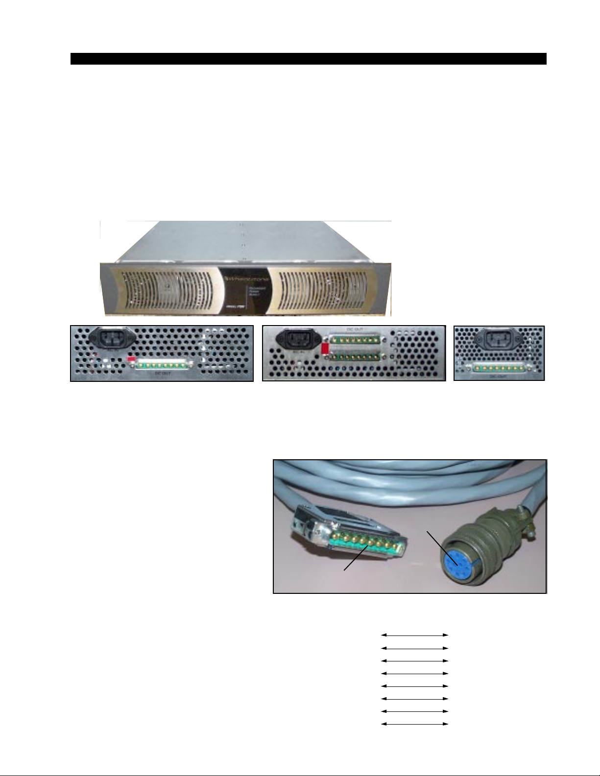
The 2001 is powered by an SPS-180, SPS-400 or SPS-40 power
supply installed in a Wheatstone Model PSR rackmount unit. The PSR
unit occupies two 19” wide rack spaces (total height 3-1/2”) and houses
up to four SPS-180 or up to two SPS-400 or SPS-40 power supply units.
Do not mount heat generating devices in the same rack cabinet.
Avoid locating any high gain equipment (such as phono preamps,
tape recorders, etc.) too near the rackmount supplies, to avoid magnetic
interference into that equipment.
Rear view of the SPS-400 unit
Rear view of the SPS-40 unit Rear view of the
If failsafe redundant supplies have been ordered,
you will be installing two
SPS-180, SPS-400, or
SPS-40 units.
Front view of the PSR
rackmount power supply
SPS-180 unit
This power supply contains high voltage circuits that are hazardous
and potentially harmful. Under no circumstances should the metal
cover be removed! If you have a problem with the power supply, the unit
must be returned to Wheatstone Corporation for repair.
Once the supply is rackmounted, it
should be connected to the 2001 using
the factory supplied cable(s). If the
2001 router is powered by the SPS180 or SPS-400 unit, the power supply
2001 Router
cable plugs into the power supply connector, located on the rear
PWIH(PWI)-2001 module in the extreme left-hand slot (looking at the
rear of the chassis). If you are using
Power Supply
End
two supplies (failsafe option), one supply will connect to each 2001 connector; otherwise only one connector will
be used (it does not matter which one).
When the 2001 is powered by the SPS40 unit, there is an additional rear PWI40 module that is mounted next to the
PWIH(PWI)-2001 module. One power
supply cable plugs into either one of the
PWIH(PWI)-2001 module’s power connectors and the second cable plugs into
2001 / Jul 01
2001 / Oct 03
Power Supply End
8-pin Connector
Male
VIO
GRN
BRN
YEL
ORG
BLK
BLU
PS Cable Pinou
PIN
1
2
3
4
5
6
7
8RED
Phantom
Digital Ground
Digital Ground
Analog Ground
Digital+
Digital+
End
-V in
+V in
PIN
VIO
E
GRN
D
BRN
F
YEL
H
G
ORG
A
BLK
C
BLU
RED
B
2001 Router End
10-pin Connector
Female
page 1 – 3
Page 14

GENERAL INFORMATION
either one of the PWI-40 module’s power connectors. If you are using
two power supplies (failsafe option) the second power supply will be
plugged into the remaining power connectors on the rear PWIH(PWI)2001 and PWI-40 modules.
Note that the power supply cable’s 10-pin female connector has to
be rotated until its locating pins match the male mating connector on
the rear of the 2001 chassis. Do not force a connector on; it attaches
easily when properly aligned. Connect the cable(s) first to the 2001,
then to the rear of the rackmount power supply.
Note that each power supply is fitted with a 3-wire grounded AC
cord that should be plugged into a "clean" AC power source. This
source should be a separate feed from those powering lighting, airconditioning, or any other non-audio machinery. The third pin ground
wire of the AC source should be tied to the central system ground point.
Failsafe Dual Redundant Supply
Wheatstone failsafe power supply systems use two SPS-180,
SPS-400 or SPS-40 rackmount power supplies for each piece of
powered equipment. Though either is capable of running a full load on
its own, in failsafe operation both units run in tandem: if one fails, the
other takes over, assuring uninterrupted operation.
In order for failsafe systems to perform as designed, always have
BOTH rackmount supplies powered up and connected to their associated equipment.
The power feed recommended in the text is often installed and referred
to in studios as an “isolated AC ground” outlet.
It is usually orange in
color.
Energizing
Assuming the 2001 and its PSR power supply are correctly
rackmounted, you may now energize the PSR rackmount power supply
by plugging it into the AC mains.
Note: To de-energize the 2001, unplug the rackmount power
supply’s AC cord from the AC mains. Never de-energize the 2001 by
disconnecting the cable that connects the router and power supply
together.
Once you have verified proper power-up, unplug the rackmount powerOnce you have verified proper power-up, unplug the rackmount power
Once you have verified proper power-up, unplug the rackmount power
Once you have verified proper power-up, unplug the rackmount powerOnce you have verified proper power-up, unplug the rackmount power
supplies to de-energize the system. You may now proceed to wire upsupplies to de-energize the system. You may now proceed to wire up
supplies to de-energize the system. You may now proceed to wire up
supplies to de-energize the system. You may now proceed to wire upsupplies to de-energize the system. You may now proceed to wire up
audio and control connections.audio and control connections.
audio and control connections.
audio and control connections.audio and control connections.
2001 / Oct 03
2001 / Jul 01
page 1 – 4
Page 15
GENERAL INFORMATION
I/O Connections
A family of I/O connector modules plug right into the cage rear to
give you a choice of DB-25 or RJ-45 connections for analog or digital
audio interface, or BNC connectors for use with 75 ohm digital audio
equipment. RJ-45 connectors are also available for use with CAT-5
wiring systems. The DB-9 connectors are used for connections to the
serial interface.
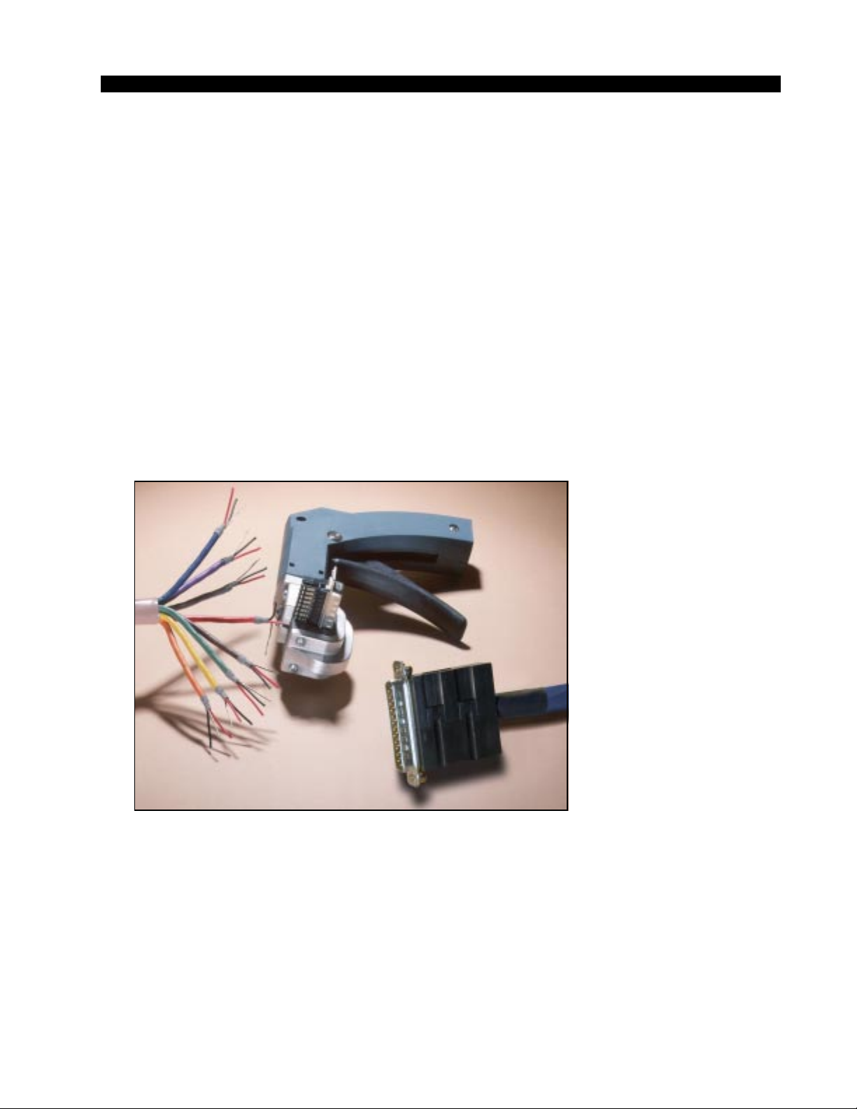
The Insulation Displacement Connector System
The DB-25 and DB-9 I/O wiring interface system is based on
insulation displacement technology. A special AMP wiring tool is
included with each system; it is auto-indexing, and allows individual
wire connections to be positively made with a single squeeze of the
tool's trigger. The trigger action is ratchet controlled, and will not
release until a full connection is made. Once released, the multipin
connector held in the tool's jaw automatically indexes to the next
connector pin. The technology is such that no stripping, soldering or
tinning of wire ends is required; all that is needed is for the wires
destined for the connector be snub cut and laid out in order (although
tubing should be used on bare drain wires). An empty DB-25 or
DB-9 connector is inserted into the tool, indexed to the first pin, and the
wires are inserted one by one into the jaw and the trigger squeezed. In
this way a single multipin connector can be completely wired up in a
minute or two.
In the event of a wiring error, connector pins may easily be removed
from the shell with the wire still attached, and inserted into the correct
position. Observe the side of the connector, with the metal part down.
You will see a row of "Vees"—simply press the top of the vee together
The AMP tool insulation displacement connector system.
Note the straight hood with
self-locking tabs. The tool,
multipin connectors (with gold
plated pins) and latching
hoods are supplied with each
2001 switcher.
2001 / Jul 01
2001 / Aug 03
page 1 – 5
Page 16

GENERAL INFORMATION
with a scribe or other sharp instrument; this will unlock the pin from the
shell, and it can be removed and inserted into the correct position.
Spread the vee apart to lock the pin in the new position. It should never
be necessary to discard a connector due to a wiring error.
Note that mating hoods for each connector are also supplied with
the console. These have locking screws that hold the connectors
securely to the rear of the router mainframe.
Digital Audio Connections
CABLE - All AES/EBU input and output digital audio connections
are balanced and should be made using a high quality digital audio
cable. Be sure to select a digital audio cable with an integral drain wire
of the same wire gauge (AWG) as the twisted pair as this facilitates an
easier consistent termination process. Typical AES/EBU digital audio
cable has a very low characteristic capacitance per ft (pF/ft), and a
nominal impedance of 110Ω. High quality digital audio cable offers
better signal transmission performance versus typical analog audio
cable, especially over long cable runs. Check the cable manufacturer’s
data sheet to be sure the cable you plan to use will work in your
application.
CONNECTORS - Typically, all AES/EBU connections are made
with the supplied DB-25 male mating connectors. These crimp style
connectors are the insulation displacement type and will accept wire
gauge 24 - 22AWG. If an optional rear panel connector type (e.g. BNC,
RJ-45, etc.) was specified and shipped with your system, please refer
to the mating connector manufacturer's recommendations for termination instructions.
Unbalanced Analog Connections
ANALOG INPUTS — Wire to the router input end with typical
shielded, two conductor cable (like Belden 9451), just as if you were
connecting a balanced source. At the unbalanced source machine’s
output, connect the + output to the HI input wire and connect the source
machine GND wire to LO, connect the shield at one end only .
Note: Unbalanced analog sources typically have -10dBv (316mV
RMS) signal levels and will not match the 2001 nominal operating
level of +4dBu (1.23V RMS). We highly recommended that you first
externally balance any unbalanced sources you plan on connecting to
the 2001. Many third party “match boxes” are commercially available
for this.
ANALOG OUTPUTS — Use a balanced output circuit which
behaves exactly like the secondary of a high-quality transformer, with
no center tap—this output is both balanced and floating. For unbalanced operation, either the HI or LO side of the analog output must be
strapped to ground of the unbalanced input, with the output taken from
the other side. (Normally you would strap LO to ground, and use HI to
feed your unbalanced equipment input.) Leave the SH floating at one
end.
2001 / Jul 01
2001 / Aug 03
page 1 – 6
Page 17

GENERAL INFORMATION
Unbalanced Digital Connections (SPDIF)
SPDIF INPUTS - The SPDIF (Sony/Phillips Digital Interface) or
“consumer” digital audio interface is a two wire unbalanced signal
typically on a single RCA style connector. Note that the SPDIF signal level
of approximately 500mV and 75 ohm impedance does not correctly match
the 2001 AES inputs. We highly recommend using a “balun” or format
converter when interfacing “consumer” grade source devices to the 2001.
In cases where a consumer grade device must be interfaced and the
appropriate matching device is not available, try wiring the SPDIF center
conductor (HOT) to the HI input pin and SPDIF shell (ground) to the LO
input. Connect SH at the 2001 router end only.
SPDIF OUTPUTS - The Bridge 2001 digital outputs are fixed, professional, AES-3 formatted outputs. SPDIF consumer format is not supported. Use an external format converter to connect the digital outputs to
consumer gear.
2001 / Jul 01
2001 / Aug 03
page 1 – 7
Page 18

HARDWARE
Hardware
Chapter Contents
Chassis/Backplane Overview ......................................................2-4
Chassis Configuration Guidelines ..............................................2-5
Audio Slots................................................................................................................ 2-5
Reserved Slots ......................................................................................................... 2-5
Backplane Termination.................................................................2-5
Digital Input Card (AES-2024)
Overview ........................................................................................2-6
AES Input Interface .......................................................................2-6
Internal Programming Options ....................................................2-6
Status LED’s ..................................................................................2-7
Hook-Ups
DB-25 - Digital Audio Connections........................................................................... 2-8
2DB-25 - Digital Audio Connections......................................................................... 2-8
8 BNC - Digital Audio Connections ......................................................................... 2-10
8 RJ-45 - Digital Audio Connections ....................................................................... 2-10
DB Panel Pinout Drawing ............................................................2-12
2DB Panel Pinout Drawing .........................................................2-12a
8 BNC Panel Pinout Drawing .................................................... 2-12b
8 RJ Panel Pinout Drawing.........................................................2-12c
Analog Input Card (ADI-2001)
Overview .......................................................................................2-13
Analog Input Interface .................................................................2-13
Internal Programming Options ...................................................2-13
Status LED’s .................................................................................2-14
Hook-Ups
Upper DB-25 - Analog Audio Connections.............................................................. 2-15
Lower DB-25 - Analog Audio Connections.............................................................. 2-15
8 RJ-45 - Analog Audio Connections ...................................................................... 2-16
2DB Panel Pinout Drawing ..........................................................2-17
8 RJ Panel Pinout Drawing..........................................................2-18
Digital Output Card (DO-2001)
Overview .......................................................................................2-19
AES Output Interface ...................................................................2-19
AES Channel Status Implementation .........................................2-20
Internal Programming Options ...................................................2-20
Status LED’s .................................................................................2-21
2001 / Jul 01
2001 / Oct 03
page 2 – 1
Page 19

HARDWARE
Hook-Ups
DB-25 - Digital Audio Connections.......................................................................... 2-22
8 BNC - Digital Audio Connections ......................................................................... 2-22
8 RJ-45 - Digital Audio Connections ....................................................................... 2-23
DB Panel Pinout Drawing ............................................................2-24
8 BNC Panel Pinout Drawing ......................................................2-25
8 RJ Panel Pinout Drawing..........................................................2-26
Analog Output Card (AO-2001)
Overview .......................................................................................2-27
Analog Output Interface ..............................................................2-27
Internal Programming Options ...................................................2-27
Status LED’s .................................................................................2-28
Hook-Ups
Upper DB-25 - Analog Audio Connections.............................................................. 2-29
Lower DB-25 - Analog Audio Connections.............................................................. 2-29
8 RJ-45 - Analog Audio Connections ...................................................................... 2-30
2DB Panel Pinout Drawing ..........................................................2-31
8 RJ Panel Pinout Drawing..........................................................2-32
Host CPU (CPU-2001)
Overview .......................................................................................2-33
Multi CPU/Failover CPU Systems ...............................................2-33
CPU-2001 BIOS Settings/Format ................................................2-33
Ethernet IP Addressing ...............................................................2-34
Ethernet Interface Wiring ............................................................2-34
Internal Programming Options ...................................................2-34
Switch Settings ............................................................................2-35
DIPSW1-SW4 - 485 Termination............................................................................. 2-35
SW5 - CPU Reset.................................................................................................... 2-35
DIPSW6 - Utility Switches ....................................................................................... 2-35
DIPSW7 - Rack ID ................................................................................................... 2-35
DIPSW8 pos.1 - Autodetect..................................................................................... 2-35
SW9 - Master Select................................................................................................ 2-36
Jumper Settings ...........................................................................2-36
J1 - RS-232 GND..................................................................................................... 2-36
J4 - AGND to DGND................................................................................................ 2-36
J5 - FPGA PGM....................................................................................................... 2-36
J6 - 48 or 44.1 kHz Sample Rate Select ................................................................. 2-36
Serial Interface Ports ...................................................................2-36
Status LED’s .................................................................................2-37
Hook-Ups
Left “A” DB-9 - Serial Interface Port1 Connections ................................................. 2-38
Right “B” DB-9 - Serial Interface Port 2 Connections.............................................. 2-38
RJ-45 - Ethernet Connections ................................................................................. 2-38
2001 / Jul 01
2001 / Apr 03
page 2 – 2
Page 20

HARDWARE
Typical Ethernet Cable ............................................................ 2-39
Typical Crossover Cable ......................................................... 2-39
PWIH Panel Pinout Drawing.................................................... 2-40
Audio Network Card (OAN-2001)
Overview ................................................................................... 2-41
Internal Programming Options ............................................... 2-42
Switch Settings ........................................................................ 2-42
DIPSW1-SW4 - 485 Termination..........................................................................2-42
DIPSW5 position 1 Local/Remote (Clock Sources) .............................................2-43
DIPSW5 position 2 Secondary/Primary................................................................2-43
DIPSW5 position 3 48kHz / 44.1kHz.................................................................... 2-43
DIPSW5 position 4 Fiber/CAT5 ............................................................................ 2-43
SW6 - Reset..........................................................................................................2-43
DIPSW7 - Rack ID ................................................................................................ 2-44
Jumper Settings ....................................................................... 2-44
J1 - Ethernet Mode Setting................................................................................... 2-44
J2 - Reset..............................................................................................................2-44
J3, J5 - Clock Selection ........................................................................................ 2-45
Status LED’s ............................................................................. 2-46
Hook-Ups
Upper “A” DB-9 - Serial Interface Port1 Connections ..........................................2-47
Lower “B” DB-9 - Serial Interface Port 2 Connections .........................................2-47
RJ-45 - Ethernet Connections ..............................................................................2-47
CAT5 Crossover Cable for OAN to OAN Connections ......... 2-47
Optical Fiber Interface ............................................................. 2-48
Connector Type ....................................................................................................2-48
Optical Fiber ......................................................................................................... 2-48
ONI Panel Pinout Drawing....................................................... 2-49
Stacking Card (CEX-2001)
Overview ................................................................................... 2-50
Configuring the Virtual Chassis ............................................. 2-50
TDM Assignment .................................................................................................. 2-50
CEX-2001 Rack ID ............................................................................................... 2-51
CEX-2001 Configuration Rules ............................................................................ 2-51
Internal Programming Options ............................................... 2-51
Switch Settings ........................................................................ 2-51
DIPSW1 - not used ............................................................................................... 2-51
SW2 - Reset..........................................................................................................2-51
DIPSW3 - TDM Assign/RackID ............................................................................2-51
Jumper Settings ....................................................................... 2-52
J1 - Crystal Select.................................................................................................2-52
J2 - Reset..............................................................................................................2-52
Status LED’s ............................................................................. 2-53
Hook-Ups .................................................................................. 2-54
2001 / Jul 01
page 2 – 3
Page 21

HARDWARE
Logic I/O Card (LIO-2001)
Overview ....................................................................................2-55
Input Ports .................................................................................2-55
Output Ports ..............................................................................2-56
Typical Input/Output Circuit.....................................................2-56
Software Programming.............................................................2-57
Internal Programming Options ................................................2-57
Jumper/Dipswitch Settings ......................................................2-57
Status LED’s ..............................................................................2-58
Hook-Ups ...................................................................................2-59
Upper “A” DB-25 - Logic In Ports Connections .....................................................2-59
Lower “B” DB-25 - Logic Out Ports Connections ..................................................2-59
LIO Panel Pinout Drawing ........................................................2-61
Quad Audio Network Card (QAT-2001)
Overview ....................................................................................2-62
Internal Programming Options ................................................2-64
Switch Settings ......................................................................... 2-64
DIPSW1, SW2, SW4 & SW5 - 485 Termination ................................................... 2-64
DIPSW7 - Fiber/CAT5 Ports A-B-C-D ................................................................... 2-65
DIPSW8 - Primary/Secondary Ports A-B-C-D.......................................................2-65
DIPSW9 - Local/Remote (Clock Source) Ports A-B-C-D ...................................... 2-65
DIPSW10 - Audio/Console (Port Type) Ports A-B-C-D.........................................2-65
SW3 - Reset...........................................................................................................2-65
DIPSW6 - Rack ID ................................................................................................. 2-66
Jumper Settings ........................................................................2-66
J1 - Factory Use Only - Reset ...............................................................................2-66
J2 - Factory Use Only - Watchdog Disable ........................................................... 2-66
J3 - Sample Rate Select - 48kHz/44.1kHz............................................................ 2-66
Status LED’s ..............................................................................2-67
Hook-Ups
Upper “A” DB-9 - Serial Interface Port1 Connections ...........................................2-69
Lower “B” DB-9 - Serial Interface Port 2 Connections ..........................................2-69
“A”, “B”, “C”, “D” RJ-45 - CAT5 Audio Network Connections ................................ 2-69
CAT5 Crossover Cable for QAT to QAT Connections ...........2-69
QCT Panel Pinout Drawing.......................................................2-70
QOT Panel Pinout Drawing ...................................................... 2-71
2001 / Jul 01
page 2 – 4
page 2 – 3a2001 / Sep 03
Page 22

HARDWARE
Digital Signal Processor Card (DSP-2001)
Overview .......................................................................................2-72
Internal Programming Options ...................................................2-72
Switch Settings ............................................................................2-73
SW1 - DSP Reset Switch ........................................................................................ 2-73
Jumper Settings ...........................................................................2-73
J1 - Factory Use Only - Watchdog Reset................................................................ 2-73
J2 - Factory Use Only - Watchdog Reset................................................................ 2-73
J3 - Factory Use Only - Watchdog Disable ............................................................. 2-73
Status LED’s .................................................................................2-74
Microphone Card (MIC-2001)
Overview .......................................................................................2-75
Analog Input Interface .................................................................2-75
Internal Programming Options ...................................................2-75
Status LED’s .................................................................................2-76
Hook-Ups
Upper DB-25 - Analog Audio Input Connections..................................................... 2-77
Lower DB-25 - Analog Audio Output Connections.................................................. 2-77
8 RJ-45 - Analog Audio Connections ...................................................................... 2-78
2DB Panel Pinout Drawing ..........................................................2-79
8 RJ Panel Pinout Drawing..........................................................2-80
2001 / Jul 01
2001 / Oct 03 page 2 – 3b
page 2 – 5
Page 23
HARDWARE
Hardware
Chassis / Backplane Overview
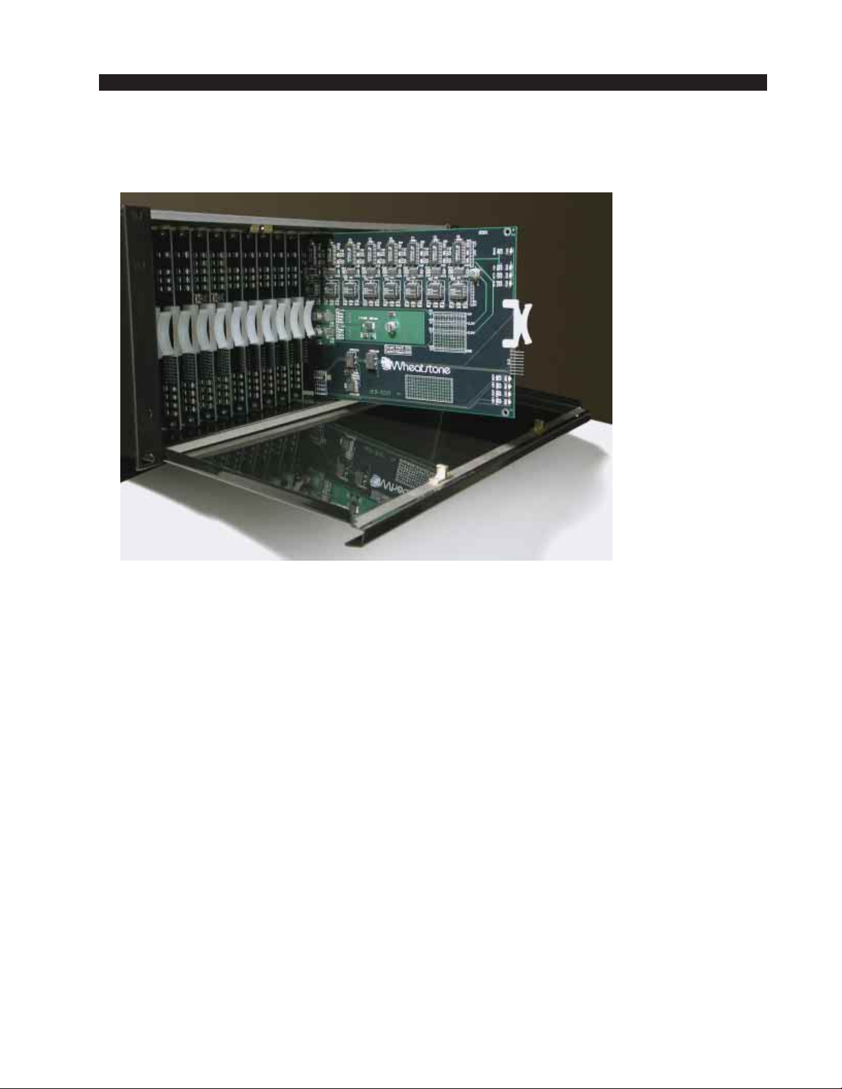
The 2001 chassis may be configured to suit a variety of I/O card
complements including—analog or digital audio input and output cards,
chassis expansion and audio network cards. A system may include a single
cage, multiple co-located cages, or a central chassis connected to one or more
satellite frames in a star configuration. All audio input and output signal
connections are made via a family of I/O connector modules that plug into
rear of the chassis. Power supply, serial control, audio network and ethernet
connections are also made on the rear of the chassis.
The backplane itself is entirely connectorized and contains a minimal
number of passive components. Further, the backplane assembly may be
removed rather easily in the rare case that service is required.
page 2 – 42001 / Jul 01
Page 24

HARDWARE
Chassis Configuration Guidelines
While new 2001 systems are pre-configured to customer specifications
at Wheatstone’s factory, future expansion of a system may require some reconfiguration of existing hardware to accommodate new resources.
Audio Slots
Audio I/O cards may be mounted in almost any slot, though there are
some basic guidelines and considerations to take into account when filling
a master or remote chassis. Room for future input and output expansion
should be taken into consideration. Further, it is useful to group input and
output cards by type (e.g. analog inputs, AES outputs, etc.) and to leave a few
blank positions following each group.
Reserved Slots
The master chassis must have a host CPU card installed in slot 22.
Systems requiring Audio Network cards must have them installed beginning
at slot 1 of the master chassis.
Remote racks must also have an Audio Network card installed in slot 1.
Stacking cards used to expand the master chassis should be located as
close to the ends of the chassis backplane as possible. One Stacking card per
chassis is required.
Note: Stacked systems connect up to 4 co-located chassis into a larger virtual
chassis (i.e. a single master chassis and up to three expansion racks).
Backplane T ermination
The high frequency nature of the electrical signals on the backplane
require that active terminator circuits be present at both ends of the chassis
backplane. The backplane assembly has special terminator card slots at each
end of its circuit board.
The master chassis has a terminator card installed at the far left end only.
The right hand termination in a master chassis is performed by the host CPU
circuit board, always installed in slot 22. Multiple CPU systems move right
end termination off the CPU circuit card onto a special terminator board
installed in slot 21.
All other frames require that terminator cards be installed in both the far
left and far right terminator card slots.
?
page 2 – 52001 / Jul 01
Page 25

HARDWARE
Digital Input Card (AES-2024)
Overview
There are two versions of digital audio input cards for the 2001:
• AES-2024/8 card will accept up to 8, AES-3 formatted stereo sources
(i.e. 16 mono channels);
• AES-2024/16 card will accept up to 16, AES-3 formatted stereo sources
(i.e. 32 mono channels);
A Signal Definitions form in the supplied XPoint software allows the
user to set attributes for the input channels including signal name, type,
circuit #, etc. The 16 (32) input channels may be configured as mono signals
(one channel), stereo signals (two channels), or 5.1 surround sound signals
(six channels) wired in any combination. Signals may span across input
cards (e.g. a surround sound signal may have 2 channels on one input card,
and 4 on a different input card).
Note: While it is possible to split the 8 (16) stereo AES inputs into 16 (32)
mono channels, there are still only 8 (16) physical wires, each containing the
2-channel AES formatted data.
A dedicated sample rate converter for each input re-clocks the incoming
audio data and phase locks it to the system’s master sample rate clock.
Embedded logic routes each channel of audio data into an available time slot
of the input card’s TDM bus. One TDM bus is allocated for each 8 input card,
2 TDM’s are used by the 16 input card.
AES Input Interface
The balanced, digital audio inputs on the AES-2024 card are transformer
coupled. AES receivers strip off the received sample rate clock and audio
data for further processing by sample rate converters. The balanced interface
operates at a nominal peak-peak input voltage of +5V with an input
impedance of 110Ω and conforms to the AES-3 1992 electrical specification. Note that Channel Status data is not forwarded.
While unbalanced SPDIF formatted input signals may be connected to
the HI and LO inputs of an AES input channel (leave the shield floating), it
is recommended that a BALUN or other external matching device be
inserted to convert the SPDIF impedance to 110Ω and signal level to at least
1V p-p. Note that the optional BNC rear panel input impedance is internally
fixed at 75Ω.
Internal Programming Options
There are no internal programming options on the AES-2024 input card.
2001 / Jul 01
2001 / Oct 03
page 2 – 6
Page 26
HARDWARE
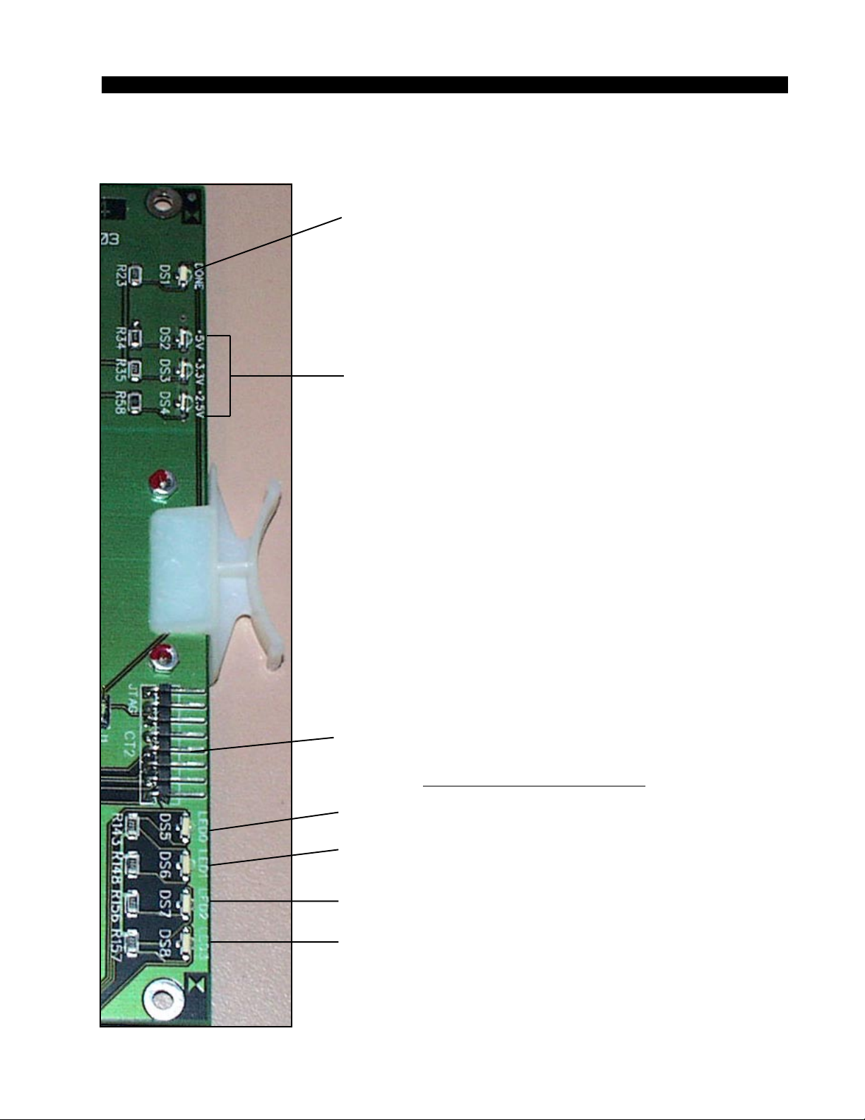
Digital Input Card Status LED’s
DONE LED (DS1) - Normally OFF;
ON when programming the FPGA,
Flashes when system clock is missing.
POWER SUPPLY STATUS (DS2-DS4) - ON indicates
power supply is OK.
2001 / Jul 01
2001 / Oct 03
JTAG HEADER - FPGA programming - factory use only.
AUXILIARY STATUS LED’s
ACTIVITY LED (DS5) - flashes on messages.
RACK ID DIPSWITCH (DS6) - ON = when SW1 pos.1 is ON,
otherwise OFF.
MUTE STATUS (DS7) - ON when the input channels
are muted.
CFG STATUS (DS8) - ON when card is not
configured.
page 2 – 7
Page 27
HARDWARE
Hook-Ups
All user wiring to the AES-2024 card takes place at the rear I/O connectors
modules: DB, 2DB, 8BNC or 8RJ-45. The DB module has one female DB-25
connector and 2DB has two DB connectors for audio input connections. The
BNC module contains eight BNC connectors for use with 75 ohm digital audio
equipment, likewise the 8RJ-45 module contains eight RJ-45 connectors for
use in balanced, unshielded twisted pair (UTP) wiring systems.
DB-25 (for AES-2024/8)—Digital Audio Connections
These include eight input sources. Pinout drawing on page 2-12 shows all
wiring connections at a glance.
Pin 24 – HI
Pin 12 – LO AES 1 In
Pin 25 – SH
Pin 1O – HI
Pin 23 – LO AES 2 In
Pin 11 – SH
Pin 21 – HI
Pin 9 – LO AES 3 In
Pin 22 – SH
Pin 7 – HI
Pin 20 – LO AES 4 In
Pin 8 – SH
Pin 18 – HI
Pin 6 – LO AES 5 In
Pin 19 – SH
Pin 4 – HI
Pin 17 – LO AES 6 In
Pin 5 – SH
Pin 15 – HI
Pin 3 – LO AES 7 In
Pin 16 – SH
Pin 1 – HI
Pin 14 – LO AES 8 In
Pin 2 – SH
2DB-25 (for AES-2024/16)—Digital Audio Connections
Upper DB-25 include eight (1-8) input sources. Pinout drawing on page
2-12a shows all wiring connections at a glance.
Pin 24 – HI
Pin 12 – LO AES 1 In
Pin 25 – SH
Pin 1O – HI
Pin 23 – LO AES 2 In
Pin 11 – SH
2001 / Jul 01
2001 / Oct 03
page 2 – 8
Page 28
HARDWARE
Pin 21 – HI
Pin 9 – LO AES 3 In
Pin 22 – SH
Pin 7 – HI
Pin 20 – LO AES 4 In
Pin 8 – SH
Pin 18 – HI
Pin 6 – LO AES 5 In
Pin 19 – SH
Pin 4 – HI
Pin 17 – LO AES 6 In
Pin 5 – SH
Pin 15 – HI
Pin 3 – LO AES 7 In
Pin 16 – SH
Pin 1 – HI
Pin 14 – LO AES 8 In
Pin 2 – SH
Lower DB-25 include eight (9-16) input sources. Pinout drawing on page 2-12a
shows all wiring connections at a glance.
Pin 24 – HI
Pin 12 – LO AES 9 In
Pin 25 – SH
Pin 1O – HI
Pin 23 – LO AES 10 In
Pin 11 – SH
Pin 21 – HI
Pin 9 – LO AES 11 In
Pin 22 – SH
Pin 7 – HI
Pin 20 – LO AES 12 In
Pin 8 – SH
Pin 18 – HI
Pin 6 – LO AES 13 In
Pin 19 – SH
Pin 4 – HI
Pin 17 – LO AES 14 In
Pin 5 – SH
Pin 15 – HI
Pin 3 – LO AES 15 In
Pin 16 – SH
Pin 1 – HI
Pin 14 – LO AES 16 In
Pin 2 – SH
2001 / Jul 01
2001 / Oct 03
page 2 – 9
Page 29
HARDWARE
8 BNC—Digital Audio Connections
This panel is used only for AES-2024/8 card. Pinout drawing on page
2-12b shows all wiring connections at a glance.
BNC 1 Pin 1 – HI
BNC 1 Pin 2 – SH
BNC 2 Pin 1 – HI
BNC 2 Pin 2 – SH
BNC 3 Pin 1 – HI
BNC 3 Pin 2 – SH
BNC 4 Pin 1 – HI
BNC 4 Pin 2 – SH
BNC 5 Pin 1 – HI
BNC 5 Pin 2 – SH
BNC 6 Pin 1 – HI
BNC 6 Pin 2 – SH
BNC 7 Pin 1 – HI
BNC 7 Pin 2 – SH
BNC 8 Pin 1 – HI
BNC 8 Pin 2 – SH
AES 1 In
AES 2 In
AES 3 In
AES 4 In
AES 5 In
AES 6 In
AES 7 In
AES 8 In
8 RJ-45—Digital Audio Connections
For AES-2024/8 digital input connections use RJ-45 #1-4 connectors,
and for AES-2024/16 use RJ-45 #1-8 connectors. Pinout drawing on page
2-12c shows all wiring connections at a glance.
2001 / Jul 01
2001 / Oct 03
RJ-45#1 Pin 3 – HI
RJ-45#1 Pin 6 – LO
RJ-45#1 Pin 1 – HI
RJ-45#1 Pin 2 – LO
RJ-45#2 Pin 3 – HI
RJ-45#2 Pin 6 – LO
RJ-45#2 Pin 1 – HI
RJ-45#2 Pin 2 – LO
RJ-45#3 Pin 3 – HI
RJ-45#3 Pin 6 – LO
RJ-45#3 Pin 1 – HI
RJ-45#3 Pin 2 – LO
RJ-45#4 Pin 3 – HI
RJ-45#4 Pin 6 – LO
RJ-45#4 Pin 1 – HI
RJ-45#4 Pin 2 – LO
RJ-45#5 Pin 3 – HI
RJ-45#5 Pin 6 – LO
RJ-45#5 Pin 1 – HI
RJ-45#5 Pin 2 – LO
AES 1 In
AES 2 In
AES 3 In
AES 4 In
AES 5 In
AES 6 In
AES 7 In
AES 8 In
AES 9 In
AES 10 In
page 2 – 10
Page 30
HARDWARE
RJ-45#6 Pin 3 – HI
RJ-45#6 Pin 6 – LO
RJ-45#6 Pin 1 – HI
RJ-45#6 Pin 2 – LO
RJ-45#7 Pin 3 – HI
RJ-45#7 Pin 6 – LO
RJ-45#7 Pin 1 – HI
RJ-45#7 Pin 2 – LO
RJ-45#8 Pin 3 – HI
RJ-45#8 Pin 6 – LO
RJ-45#8 Pin 1 – HI
RJ-45#8 Pin 2 – LO
AES 11 In
AES 12 In
AES 13 In
AES 14 In
AES 15 In
AES 16 In
2001 / Jul 01
2001 / Oct 03
page 2 – 11
Page 31
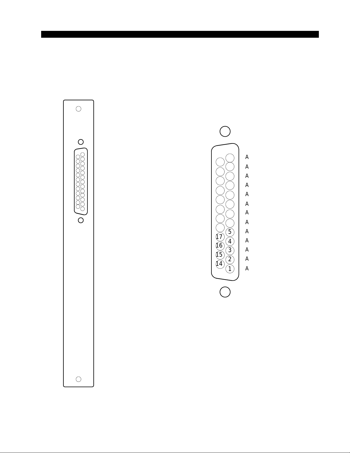
A
D
HARDWARE
DB Panel
Digital Input Connections
for AES-2024/8
I/O PORTS
("A" DB-25)
AES 1 IN SH
AES 1 IN HI
AES 2 IN LO
AES 3 IN SH
AES 3 IN HI
AES 4 IN LO
AES 5 IN SH
AES 5 IN HI
AES 6 IN LO
AES 7 IN SH
AES 7 IN HI
AES 8 IN LO
25
24
23
22
21
20
19
18
17
16
15
14
13
12
11
10
9
8
7
6
5
4
3
2
1
AUDIO GROUN
AES 1 IN LO
AES 2 IN SH
AES 2 IN HI
AES 3 IN LO
AES 4 IN SH
AES 4 IN HI
AES 5 IN LO
AES 6 IN SH
AES 6 IN HI
AES 7 IN LO
AES 8 IN SH
AES 8 IN HI
2001 / Jul 01
2001 / Oct 03
page 2 – 12
Page 32
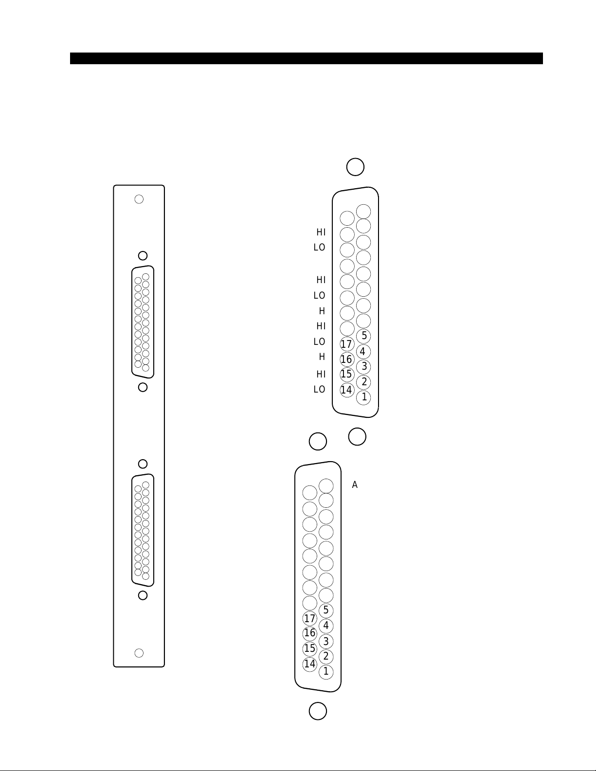
HARDWARE
)
)
2DB Panel
Digital Input Connections
for AES-2024/16
A
B
I/O PORTS
(Upper "A"
DB-25
AES 9 IN SH
AES 9 IN HI
AES10 IN LO
AES11 IN SH
AES11 IN HI
AES12 IN LO
AES13 IN SH
AES13 IN HI
AES14 IN LO
AES15 IN SH
AES15 IN HI
AES16 IN LO
AES 1 IN SH
AES 1 IN HI
AES 2 IN LO
AES 3 IN SH
AES 3 IN HI
AES 4 IN LO
AES 5 IN SH
AES 5 IN HI
AES 6 IN LO
AES 7 IN SH
AES 7 IN HI
AES 8 IN LO
25
24
23
22
21
20
19
18
17
16
15
14
13
12
11
10
9
8
7
6
5
4
3
2
1
13
25
12
24
11
23
10
22
21
20
19
18
17
16
15
14
AUDIO GROUND
AES 9 IN LO
AES10 IN SH
AES10 IN HI
AES11 IN LO
AES12 IN SH
AES12 IN HI
AES13 IN LO
AES14 IN SH
AES14 IN HI
AES15 IN LO
AES16 IN SH
AES16 IN HI
AUDIO GROUND
AES 1 IN LO
AES 2 IN SH
AES 2 IN HI
AES 3 IN LO
9
AES 4 IN SH
8
AES 4 IN HI
7
5
3
2
1
AES 5 IN LO
AES 6 IN SH
AES 6 IN HI
AES 7 IN LO
AES 8 IN SH
AES 8 IN HI
6
4
I/O PORTS
(Lower "B"
DB-25
page 2 – 12a
2001 / Jul 01
2001 / Oct 03
page 2 – 13
Page 33
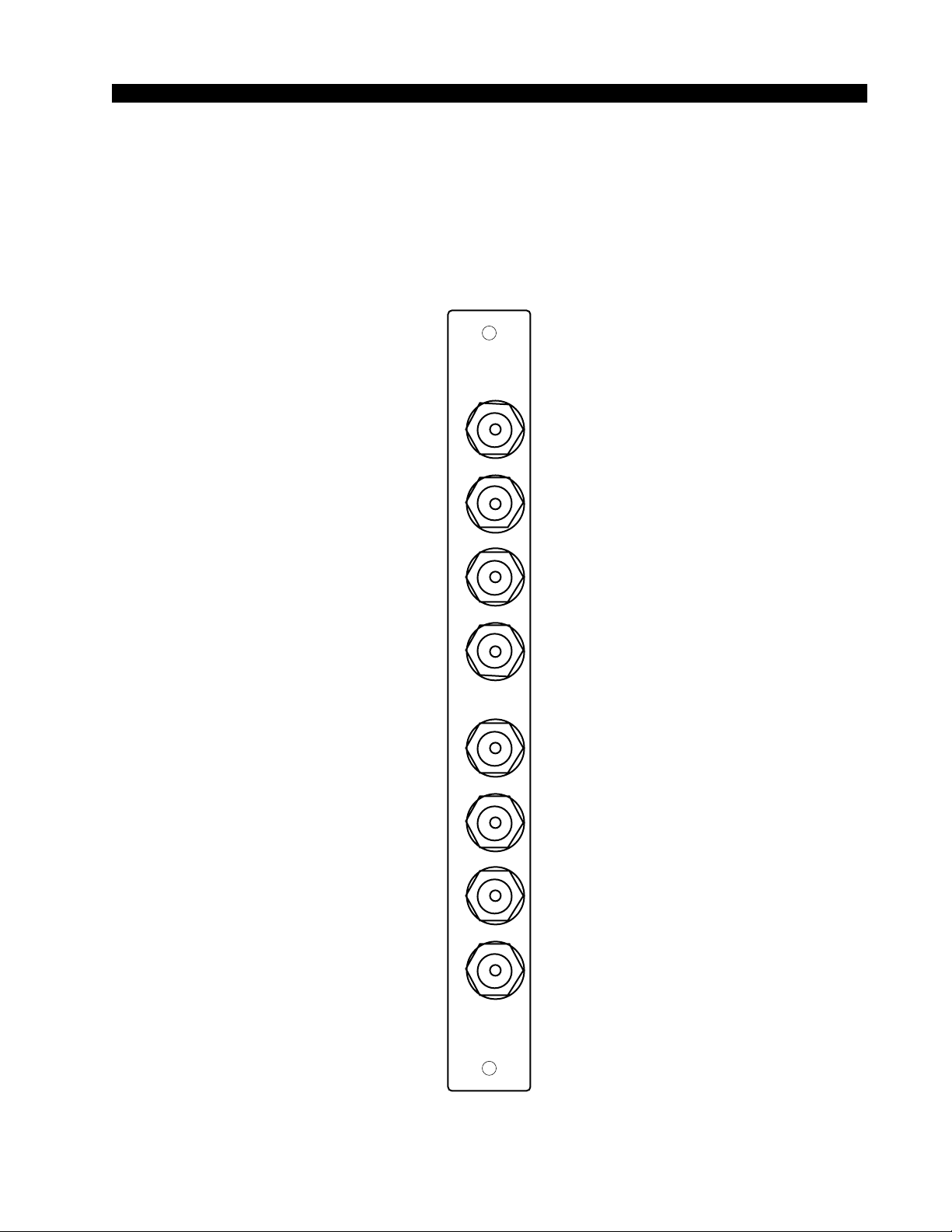
HARDWARE
8 BNC Panel
Digital Input Connections
for AES-2024/8
1
AES1 IN
AES2 IN
AES3 IN
AES4 IN
AES5 IN
AES6 IN
HI
SH
HI
SH
HI
SH
HI
SH
HI
SH
HI
SH
ΩΩ
75ΩΩ
2001 / Jul 01
2001 / Oct 03
AES7 IN
AES8 IN
HI
SH
HI
SH
8
page 2 – 12b
page 2 – 14
Page 34
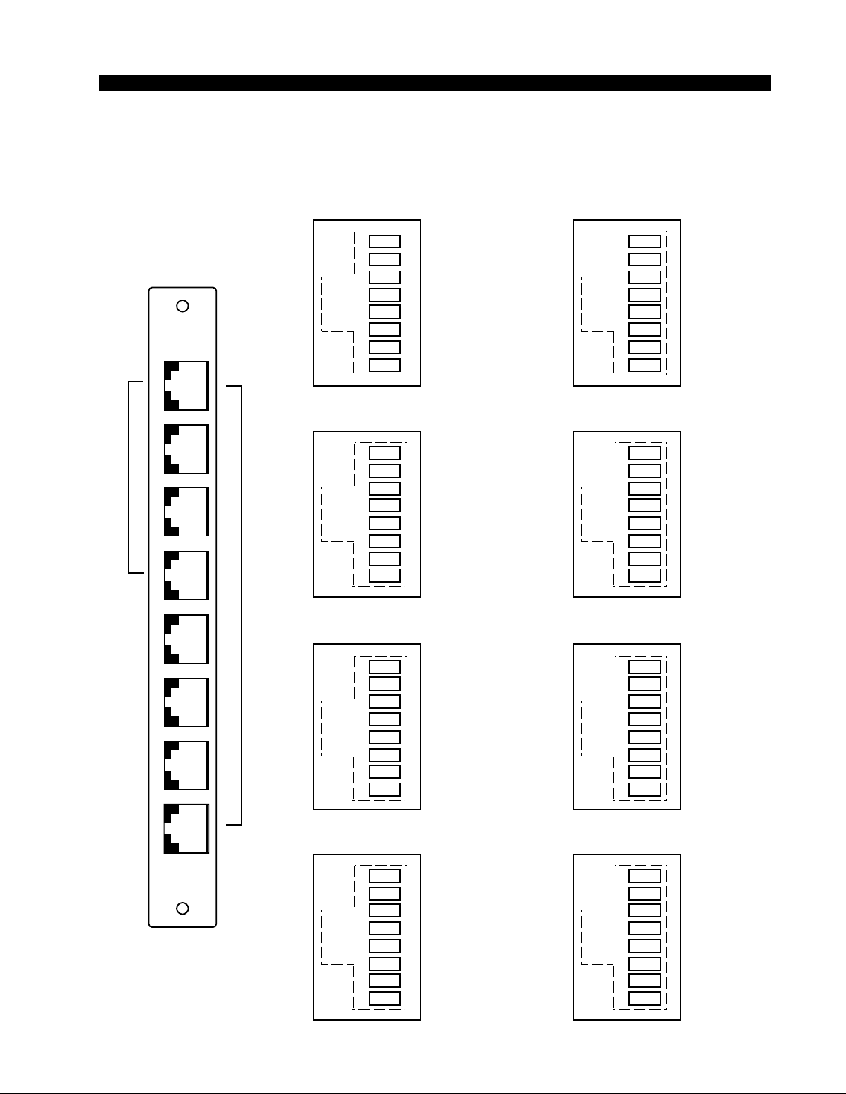
HARDWARE
8RJ Panel
Digital Input Connections
FOR
AES-2024/8
RJ-45 #1
1
2
3
4
5
6
1
7
8
AES 2 IN HI
AES 2 IN LO
AES 1 IN HI
AES 1 IN LO
RJ-45 #2
1
2
3
4
5
6
7
8
FOR
AES-2024/16
AES 4 IN HI
AES 4 IN LO
AES 3 IN HI
AES 3 IN LO
RJ-45 #3
RJ-45 #5
1
2
3
4
5
6
7
8
RJ-45 #6
1
2
3
4
5
6
7
8
RJ-45 #7
AES 10 IN HI
AES 10 IN LO
AES 9 IN HI
AES 9 IN LO
AES 12 IN HI
AES 12 IN LO
AES 11 IN HI
AES 11 IN LO
2001 / Jul 01
2001 / Oct 03
1
2
3
4
5
6
7
8
RJ-45 #4
8
1
2
3
4
5
6
7
8
AES 6 IN HI
AES 6 IN LO
AES 5 IN HI
AES 5 IN LO
AES 8 IN HI
AES 8 IN LO
AES 7 IN HI
AES 7 IN LO
1
2
3
4
5
6
7
8
RJ-45 #8
1
2
3
4
5
6
7
8
AES 14 IN HI
AES 14 IN LO
AES 13 IN HI
AES 13 IN LO
AES 16 IN HI
AES 16 IN LO
AES 15 IN HI
AES 15 IN LO
page 2 – 12c
page 2 – 15
Page 35

HARDWARE
Analog Input Card (ADI-2001)
Overview
The Analog input cards accept up to 8 stereo analog audio sources (i.e.16
mono channels). A Signal Definitions form in the supplied XPoint software
allows the user to set attributes for the input channel hardware including signal
name, type, circuit #, etc. The 16 input channels may be configured as mono
signals (one channel), stereo signals (two channels), or 5.1 surround sound
signals (six channels) in any combination. Signals may span across input cards
(e.g. a surround sound signal may have 4 channels on one input card, and 2
channels on a different input card).
The balanced, line level analog input signals are buffered and converted to
the digital domain by 24bit A-D converters operating at the system’s master
sample rate. Embedded logic routes each channel of audio data into an
available time slot of the input card’s TDM bus. One TDM bus is allocated for
each input card.
Analog Input Interface
The balanced analog input stages are direct coupled, unity gain circuits and
operate at a nominal input level of +4dBu. The input impedance is 20kΩ. A
+4dBu input signal will result in a -20dBFS digital output level at any of the
selected AES outputs. The maximum analog input signal level is +24 dBu
providing 20 dB of headroom above the nominal input level.
Reference Notes:
0dBu = .7746 V RMS, +4dBu = 1.23V RMS
dBFS = dB Full Scale Digital
-20dBFS = +4dBu
Internal Programming Options
There are no internal programming options on the ADI-2001 card.
page 2 – 132001 / Jul 01
Page 36
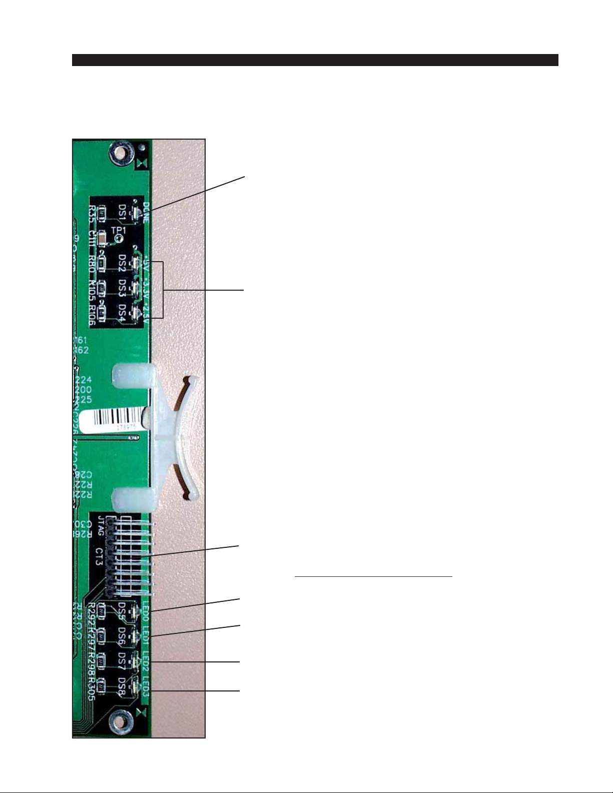
HARDWARE
Analog Input Card Status LED’ s
DONE LED (DS1) - Normally OFF;
ON when programming the FPGA ,
Flashes when system clock is missing.
POWER SUPPLY STATUS (DS2-DS4) - ON indicates
power supply is OK.
JTAG HEADER - FPGA programming - factory use only.
AUXILIARY STATUS LED’s
ACTIVITY LED (DS5) - flashes on messages.
RACK ID DIPSWITCH (DS6) - ON = when SW1 pos.1 is ON,
otherwise OFF.
MUTE STATUS (DS7) - ON when the input channels
are muted.
CFG STATUS (DS8) - ON when card is not
configured.
page 2 – 142001 / Jul 01
Page 37
HARDWARE
Hook-Ups
All user wiring to the ADI-2001 card takes place at the rear I/O connectors
modules: 2DB or 8RJ-45. The 2DB module has two female DB-25 connectors for
audio input connections. The 8RJ-45 module contains eight RJ-45 connectors for use
in balanced, unshielded twisted pair (UTP) wiring systems.
Upper DB-25—Analog Audio Connections
These include four (1-4) input sources. Pinout drawing on page 2-17 shows all
wiring connections at a glance.
Pin 24 – HI
Pin 12 – LO Channel 1 (Stereo 1 Lt) In
Pin 25 – SH
Pin 10 – HI
Pin 23 – LO Channel 2 (Stereo 1 Rt) In
Pin 11 – SH
Pin 21 – HI
Pin 9 – LO Channel 3 (Stereo 2 Lt) In
Pin 22 - SH
Pin 7 – HI
Pin 20 – LO Channel 4 (Stereo 2 Rt) In
Pin 8 – SH
Pin 18 – HI
Pin 6 – LO Channel 5 (Stereo 3 Lt) In
Pin 19 – SH
Pin 4 – HI
Pin 17 – LO Channel 6 (Stereo 3 Rt) In
Pin 5 – SH
Pin 15 – HI
Pin 3 – LO Channel 7 (Stereo 4 Lt) In
Pin 16 – SH
Pin 1 – HI
Pin 14 – LO Channel 8 (Stereo 4 Rt) In
Pin 2 – SH
Lower DB-25—Analog Audio Connections
These include four (5-8) input sources. Pinout drawing on page 2-17 shows all
wiring connections at a glance.
Pin 24 – HI
Pin 12 – LO Channel 9 (Stereo 5 Lt) In
Pin 25 – SH
Pin 10 – HI
Pin 23 – LO Channel 10 (Stereo 5 Rt) In
Pin 11 – SH
Pin 21 – HI
Pin 9 – LO Channel 11 (Stereo 6 Lt) In
Pin 22 - SH
page 2 – 152001 / Jul 01
Page 38
HARDWARE
Pin 7 – HI
Pin 20 – LO Channel 12 (Stereo 6 Rt) In
Pin 8 – SH
Pin 18 – HI
Pin 6 – LO Channel 13 (Stereo 7 Lt) In
Pin 19 – SH
Pin 4 – HI
Pin 17 – LO Channel 14 (Stereo 7 Rt) In
Pin 5 – SH
Pin 15 – HI
Pin 3 – LO Channel 15 (Stereo 8 Lt) In
Pin 16 – SH
Pin 1 – HI
Pin 14 – LO Channel 16 (Stereo 8 Rt) In
Pin 2 – SH
8 RJ-45—Analog Audio Connections
Pinout drawing on pages 2-18 shows all wiring connections at a glance.
RJ-45#1 Pin 3 – HI
RJ-45#1 Pin 6 – LO
RJ-45#1 Pin 1 – HI
RJ-45#1 Pin 2 – LO
RJ-45#2 Pin 3 – HI
RJ-45#2 Pin 6 – LO
RJ-45#2 Pin 1 – HI
RJ-45#2 Pin 2 – LO
RJ-45#3 Pin 3 – HI
RJ-45#3 Pin 6 – LO
RJ-45#3 Pin 1 – HI
RJ-45#3 Pin 2 – LO
RJ-45#4 Pin 3 – HI
RJ-45#4 Pin 6 – LO
RJ-45#4 Pin 1 – HI
RJ-45#4 Pin 2 – LO
RJ-45#5 Pin 3 – HI
RJ-45#5 Pin 6 – LO
RJ-45#5 Pin 1 – HI
RJ-45#5 Pin 2 – LO
RJ-45#6 Pin 3 – HI
RJ-45#6 Pin 6 – LO
RJ-45#6 Pin 1 – HI
RJ-45#6 Pin 2 – LO
RJ-45#7 Pin 3 – HI
RJ-45#7 Pin 6 – LO
RJ-45#7 Pin 1 – HI
RJ-45#7 Pin 2 – LO
RJ-45#8 Pin 3 – HI
RJ-45#8 Pin 6 – LO
RJ-45#8 Pin 1 – HI
RJ-45#8 Pin 2 – LO
Channel 1 (Stereo1 Lt) In
Channel 2 (Stereo 1 Rt) In
Channel 3 (Stereo 2 Lt) In
Channel 4 (Stereo 2 Rt) In
Channel 5 (Stereo 3 Lt) In
Channel 6 (Stereo 3 Rt) In
Channel 7 (Stereo 4 Lt) In
Channel 8 (Stereo 4 Rt) In
Channel 9 (Stereo 5 Lt) In
Channel 10 (Stereo 5 Rt) In
Channel 11 (Stero 6 Lt) In
Channel 12 (Stereo 6 Rt) In
Channel 13 (Stereo 7 Lt) In
Channel 14 (Stereo 7 Rt) In
Channel 15 (Stereo 8 Lt) In
Channel 16 (Stereo 8 Rt) In
page 2 – 162001 / Jul 01
Page 39
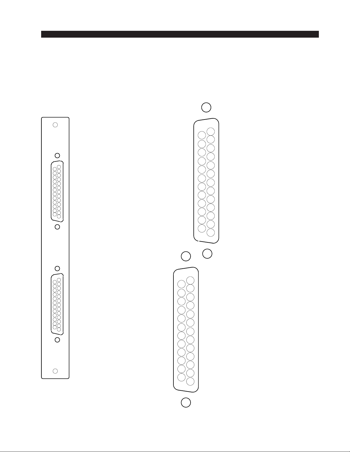
HARDWARE
)
)
2DB Panel
Analog Input Connections
AUDIO GROUND
CHANNEL 1 (STEREO 1 LT) IN SH
A
I/O PORTS
(Upper "A"
DB-25
CHANNEL 1 (STEREO 1 LT) IN HI
CHANNEL 2 (STEREO 1 RT) IN LO
CHANNEL 3 (STEREO 2 LT) IN SH
CHANNEL 3 (STEREO 2 LT) IN HI
CHANNEL 4 (STEREO 2 RT) IN LO
CHANNEL 5 (STEREO 3 LT) IN SH
CHANNEL 5 (STEREO 3 LT) IN HI
CHANNEL 6 (STEREO 3 RT) IN LO
CHANNEL 7 (STEREO 4 LT) IN SH
CHANNEL 7 (STEREO 4 LT) IN HI
CHANNEL 8 (STEREO 4 RT) IN LO
25
24
23
22
21
20
19
18
17
16
15
14
13
12
CHANNEL 1 (STEREO 1 LT) IN LO
CHANNEL 2 (STEREO 1 RT) IN SH
11
CHANNEL 2 (STEREO 1 RT) IN HI
10
CHANNEL 3 (STEREO 2 LT) IN LO
9
CHANNEL 4 (STEREO 2 RT) IN SH
8
CHANNEL 4 (STEREO 2 RT) IN HI
7
CHANNEL 5 (STEREO 3 LT) IN LO
6
CHANNEL 6 (STEREO 3 RT) IN SH
5
CHANNEL 6 (STEREO 3 RT) IN HI
4
CHANNEL 7 (STEREO 4 LT) IN LO
3
CHANNEL 8 (STEREO 4 RT) IN SH
2
CHANNEL 8 (STEREO 4 RT) IN HI
1
CHANNEL 9 (STEREO 5 LT) IN SH
CHANNEL 9 (STEREO 5 LT) IN HI
CHANNEL 10 (STEREO 5 RT) IN LO
CHANNEL 11 (STEREO 6 LT) IN SH
CHANNEL 11 (STEREO 6 LT) IN HI
CHANNEL 12 (STEREO 6 RT) IN LO
CHANNEL 13 (STEREO 7 LT) IN SH
CHANNEL 13 (STEREO 7 LT) IN HI
B
CHANNEL 14 (STEREO 7 RT) IN LO
CHANNEL 15 (STEREO 8 LT) IN SH
CHANNEL 15 (STEREO 8 LT) IN HI
CHANNEL 16 (STEREO 8 RT) IN LO
25
24
23
22
21
20
19
18
17
16
15
14
13
12
11
10
AUDIO GROUND
CHANNEL 9 (STEREO 5 LT) IN LO
CHANNEL 10 (STEREO 5 RT) IN SH
CHANNEL 10 (STEREO 5 RT) IN HI
CHANNEL 11 (STEREO 6 LT) IN LO
9
CHANNEL 12 (STEREO 6 RT) IN SH
8
CHANNEL 12 (STEREO 6 RT) IN HI
7
CHANNEL 13 (STEREO 7 LT) IN LO
6
CHANNEL 14 (STEREO 7 RT) IN SH
5
CHANNEL 14 (STEREO 7 RT) IN HI
4
CHANNEL 15 (STEREO 8 LT) IN LO
3
CHANNEL 16 (STEREO 8 RT) IN SH
2
CHANNEL 16 (STEREO 8 RT) IN HI
1
I/O PORTS
(Lower "B"
DB-25
page 2 – 172001 / Jul 01
Page 40
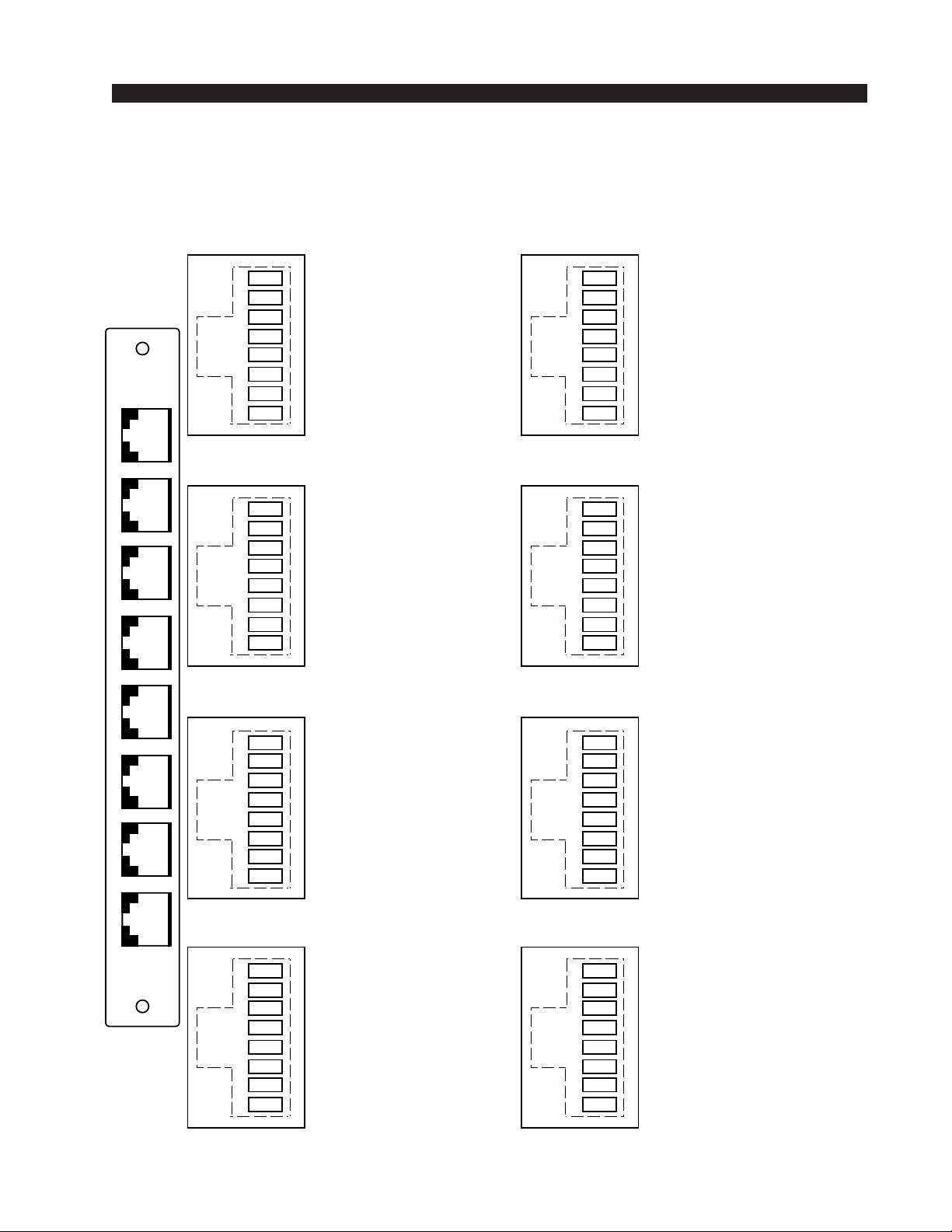
HARDWARE
8RJ Panel
Analog Input Connections
RJ-45 #1
1
2
3
4
5
6
1
7
8
CHANNEL 2 (STEREO 1 RT) IN HI
CHANNEL 2 (STEREO 1 RT) IN LO
CHANNEL 1 (STEREO 1 LT) IN HI
CHANNEL 1(STEREO 1 LT) IN LO
RJ-45 #2
1
2
3
4
5
6
7
8
CHANNEL 4 (STEREO 2 RT) IN HI
CHANNEL 4 (STEREO 2 RT) IN LO
CHANNEL 3 (STEREO 2 LT) IN HI
CHANNEL 3 (STEREO 2 LT) IN LO
RJ-45 #5
1
2
3
4
5
6
7
8
RJ-45 #6
1
2
3
4
5
6
7
8
CHANNEL 10 (STEREO 5 RT) OUT HI
CHANNEL 10 (STEREO 5 RT) OUT LO
CHANNEL 9 (STEREO 5 LT) OUT HI
CHANNEL 9 (STEREO 5 LT) IN LO
CHANNEL 12 (STEREO 6 RT) IN HI
CHANNEL 12 (STEREO 6 RT) IN LO
CHANNEL 11 (STEREO 6 LT) IN HI
CHANNEL 11 (STEREO 6 LT) IN LO
RJ-45 #3
1
2
3
4
5
6
7
8
CHANNEL 6 (STEREO 3 RT) IN HI
CHANNEL 6 (STEREO 3 RT) IN LO
CHANNEL 5 (STEREO 3 LT) IN HI
CHANNEL 5 (STEREO 3 LT) IN LO
RJ-45 #4
8
1
2
3
4
5
6
7
8
CHANNEL 8 (STEREO 4 RT) IN HI
CHANNEL 8 (STEREO 4 RT) IN LO
CHANNEL 7 (STEREO 4 LT) IN HI
CHANNEL 7 (STEREO 4 LT) IN LO
RJ-45 #7
1
2
3
4
5
6
7
8
RJ-45 #8
1
2
3
4
5
6
7
8
CHANNEL 14 (STEREO 7 RT) IN HI
CHANNEL 14 (STEREO 7 RT) IN LO
CHANNEL 13 (STEREO 7 LT) IN HI
CHANNEL 13 (STEREO 7 LT) IN LO
CHANNEL 16 (STEREO 8 RT) IN HI
CHANNEL 16 (STEREO 8 RT) IN LO
CHANNEL 15 (STEREO 8 LT) IN HI
CHANNEL 15 (STEREO 8 LT) IN LO
page 2 – 182001 / Jul 01
Page 41

HARDWARE
Digital Output Card (DO-2001)
Overview
Each Digital Output card provides 8 physical AES-3 formatted outputs.
The eight physical AES outputs are divided into 16 channels or circuits in
software to allow the greatest routing flexibility. A Signal Definitions form
in the supplied XPoint software allows the user to set attributes for the output
channels including signal name, type, circuit #, etc. The 8 AES outputs are
configured in software to be any combination of mono, stereo or 5.1 output
signals. For example, the card is normally configured as 8 stereo outputs, but
might also be configured as, 4 stereo outputs and 8 mono outputs. Many
combinations are possible up to the card’s 16 channel limit. 5.1 signals may
span across two DO-2001 output cards.
Each output card listens for connection commands from the CPU card,
and then uses this information to connect the appropriate sources to their
selected output channels. The selected audio data is fed to AES transmitters
which format the 24 bit audio data according to the AES-3 standard.
Note: While it is possible to split the 8 stereo AES outputs into 16 mono
channels, there are still only 8 physical wires, each containing the 2-channel
AES formatted data.
AES Output Interface
The balanced digital audio outputs on the DO-2001 card are transformer
coupled and exhibit a nominal output impedance of 110Ω. This interface
operates at a nominal output voltage of +5V p-p and conforms to the AES3 1992 electrical specification. The DO-2001 output cards operate at unity
gain and transmit 24bit audio data word lengths at the system sample rate.
Output sample rate is set to 44.1 kHz or 48 kHz via certain settings on the
CPU-2001 card. Optionally, the CPU’s External AES Sync input may be
used to slave the system to a user provided 44.1 kHz or 48 kHz reference rate.
Please refer to the CPU-2001 hardware section for details on external
synchronization.
The digital output signal reference level is -20dBFS. A +4dBu analog
input signal yields a -20dBFS digital output signal. Channel Status implementation complies with rules for “Standard implementation” as described
in the AES-3 1992 specification.
page 2 – 192001 / Jul 01
Page 42
HARDWARE
AES Channel Status Implementation
The following embedded channel status information is transmitted at the
AES digital outputs along with the audio data.
Note: Channel Status bits are identically set for channels 1 and 2.
CHANNEL STATUS: PROFESSIONAL
DATA USE: AUDIO (normal mode)
EMPHASIS: NO EMPHASIS
SOURCE Fs LOCK: LOCKED
SAMPLE FREQUENCY: 44.1 kHz or 48 kHz*
CHANNEL MODE: STEREO
USER BITS MODE: NONE
AUX BITS USE: 24 BIT - main audio
AUDIO WORD LENGTH: 24 BIT
REFERENCE SIGNAL: NOT A REFERENCE SIGNAL
ORIGIN: NOT INDICATED
DESTINATION: NOT INDICATED
SAMPLE #: Ø
TIME OF DAY: ØØ : ØØ : ØØ
BLOCK CRC: IS VALID
Internal Programming Options
DO-2001PCB SW2
POSITION
FUNCTION
* The Sample Rate frequency
reported in the channel status
block depends upon a dipswitch
setting on the DO-2001 circuit
board. DipSW2 - pos.3: OFF =
48 kHz, ON = 44.1 kHz.
NOTE: When changing the audio sample rate of
the Bridge 2001 Digital Audio Network Router,
changes must be made in the following places:
DO-2001 Digital Output Card, CPU-2001 Host
CPU, OAN-2001 Audio Network Card, CEX-2001
Stacking Card, and QAT-2001 Quad Audio Network Card. See the appropriate manual sections
for details.
ON OFF
1
2
3
4
UNUSED
UNUSED
CHANNEL STATUS Fs
CHANNEL STATUS
IMPLEMENTATION
N/A N/A
N/A N/A
44.1 kHz 48 kHz
MINIMUM STANDARD
Internal programming is made via PCB mounted dipswitch SW2.
Note: Dipswitch SW2 position 3 sets the reported output sample rate
frequency transmitted in a channel status block. This dipswitch does not
change the physical sample rate.
2001 / Jul 01
2001 / Mar 05
page 2 – 20
Page 43
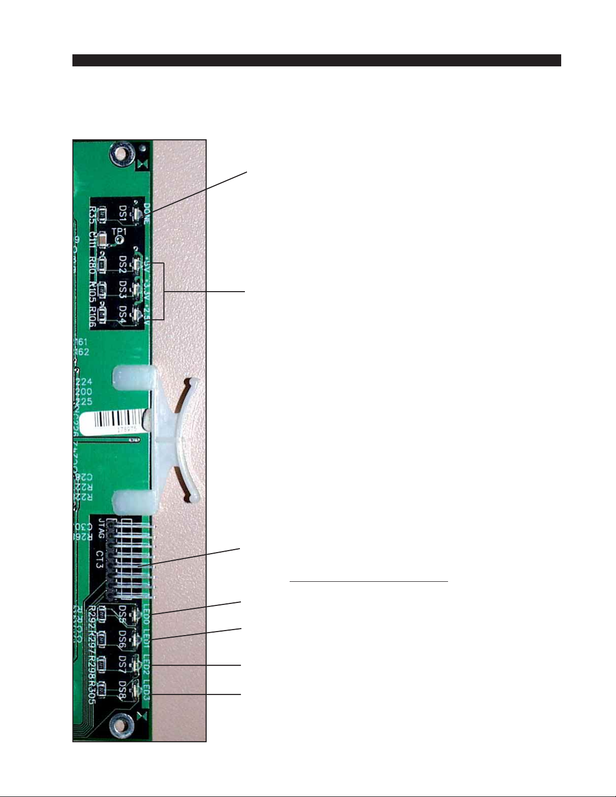
HARDWARE
Digital Output Card Status LED’ s
DONE LED (DS1) - Normally OFF;
ON when programming the FPGA ,
Flashes when system clock is missing.
POWER SUPPLY STATUS (DS2-DS4) - ON indicates
power supply is OK.
JTAG HEADER - FPGA programming - factory use only.
AUXILIARY STATUS LED’s
ACTIVITY LED (DS5) - flashes on messages.
RACK ID DIPSWITCH (DS6) - ON = when SW1 pos.1 is ON,
otherwise OFF.
MUTE STATUS (DS7) - ON when the output channels
are muted.
CFG STATUS (DS8) - ON when card is not
configured.
page 2 – 212001 / Jul 01
Page 44
HARDWARE
Hook-Ups
All user wiring from the DO-2001 card takes place at the rear I/O
connectors modules: DB and 8 BNC. The DB module has one female DB25 connector for digital audio output connections. The 8 BNC module
contains eight BNC connectors for use with 75 ohm digital audio equipment.
DB-25—Digital Audio Connections
These include eight outputs. Pinout drawing on page 2-24 shows all
wiring connections at a glance.
Pin 24 – HI
Pin 12 – LO AES 1 Out
Pin 25 – SH
Pin 1O – HI
Pin 23 – LO AES 2 Out
Pin 11 – SH
Pin 21 – HI
Pin 9 – LO AES 3 Out
Pin 22 – SH
Pin 7 – HI
Pin 20 – LO AES 4 Out
Pin 8 – SH
Pin 18 – HI
Pin 6 – LO AES 5 Out
Pin 19 – SH
Pin 4 – HI
Pin 17 – LO AES 6 Out
Pin 5 – SH
Pin 15 – HI
Pin 3 – LO AES 7 Out
Pin 16 – SH
Pin 1 – HI
Pin 14 – LO AES 8 Out
Pin 2 – SH
8 BNC—Digital Audio Connections
Pinout drawing on page 2-25 shows all wiring connections at a glance.
BNC 1 Pin 1 – HI
BNC 1 Pin 2 – SH
BNC 2 Pin 1 – HI
BNC 2 Pin 2 – SH
BNC 3 Pin 1 – HI
BNC 3 Pin 2 – SH
AES 1 Out
AES 2 Out
AES 3 Out
page 2 – 222001 / Jul 01
Page 45
HARDWARE
BNC 4 Pin 1 – HI
BNC 4 Pin 2 – SH
BNC 5 Pin 1 – HI
BNC 5 Pin 2 – SH
BNC 6 Pin 1 – HI
BNC 6 Pin 2 – SH
BNC 7 Pin 1 – HI
BNC 7 Pin 2 – SH
AES 4 Out
AES 5 Out
AES 6 Out
AES 7 Out
BNC 8 Pin 1 – HI
BNC 8 Pin 2 – SH
AES 8 Out
8 RJ-45—Digital Audio Connections
For digital output connections use RJ-45 #1-4 connectors. Pinout drawing
on page 2-26 shows all wiring connections at a glance.
RJ-45#1 Pin 3 – HI
RJ-45#1 Pin 6 – LO
RJ-45#1 Pin 1 – HI
RJ-45#1 Pin 2 – LO
RJ-45#2 Pin 3 – HI
RJ-45#2 Pin 6 – LO
RJ-45#2 Pin 1 – HI
RJ-45#2 Pin 2 – LO
RJ-45#3 Pin 3 – HI
RJ-45#3 Pin 6 – LO
RJ-45#3 Pin 1 – HI
RJ-45#3 Pin 2 – LO
RJ-45#4 Pin 3 – HI
RJ-45#4 Pin 6 – LO
RJ-45#4 Pin 1 – HI
RJ-45#4 Pin 2 – LO
AES 1 Out
AES 2 Out
AES 3 Out
AES 4 Out
AES 5 Out
AES 6 Out
AES 7 Out
AES 8 Out
page 2 – 232001 / Jul 01
Page 46
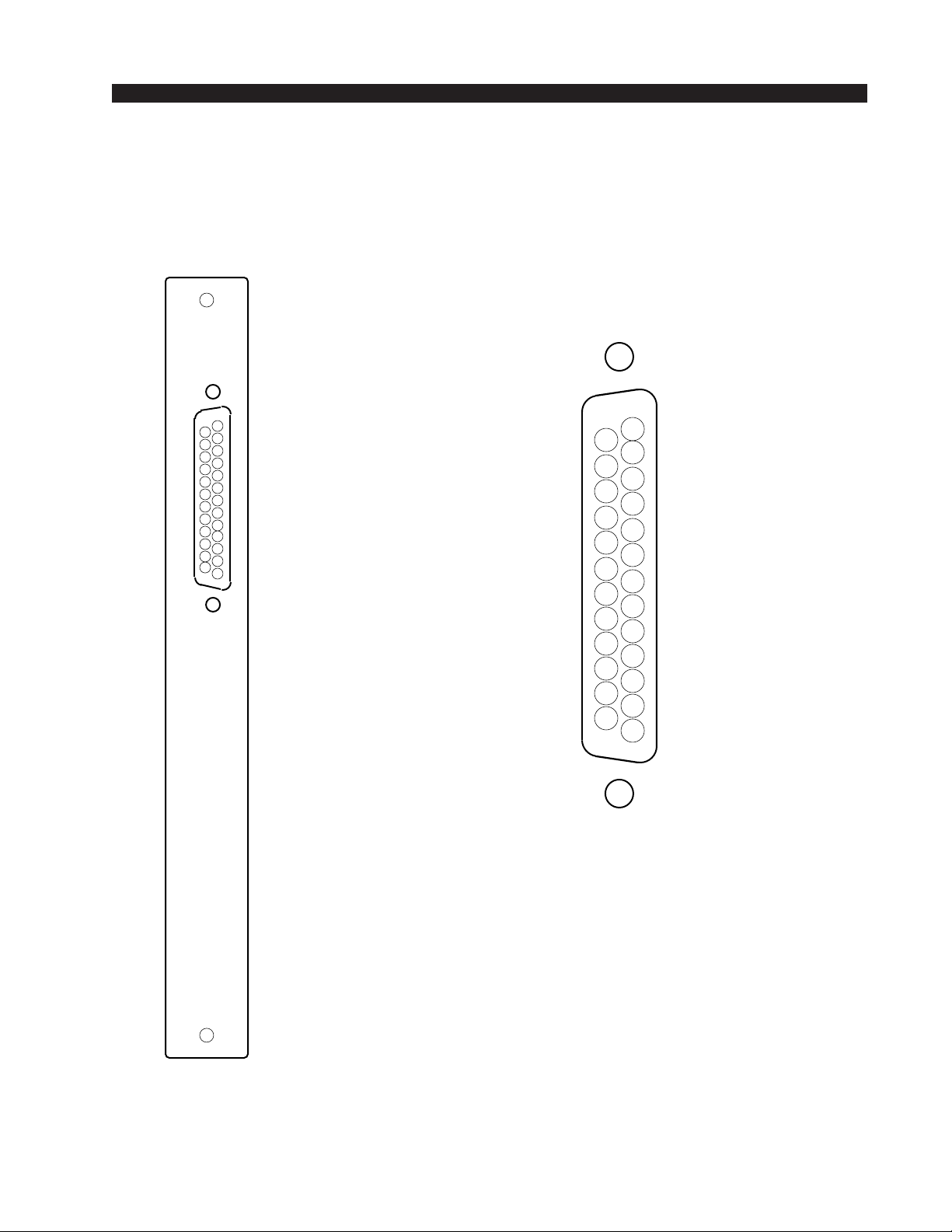
D
A
HARDWARE
DB Panel
Digital Output Connections
I/O PORTS
("A" DB-25)
AES 1 OUT SH
AES 1 OUT HI
AES 2 OUT LO
AES 3 OUT SH
AES 3 OUT HI
AES 4 OUT LO
AES 5 OUT SH
AES 5 OUT HI
AES 6 OUT LO
AES 7 OUT SH
AES 7 OUT HI
AES 8 OUT LO
25
24
23
22
21
20
19
18
17
16
15
14
13
12
11
10
9
8
7
6
5
4
3
2
1
AUDIO GROUN
AES 1 OUT LO
AES 2 OUT SH
AES 2 OUT HI
AES 3 OUT LO
AES 4 OUT SH
AES 4 OUT HI
AES 5 OUT LO
AES 6 OUT SH
AES 6 OUT HI
AES 7 OUT LO
AES 8 OUT SH
AES 8 OUT HI
page 2 – 242001 / Jul 01
Page 47
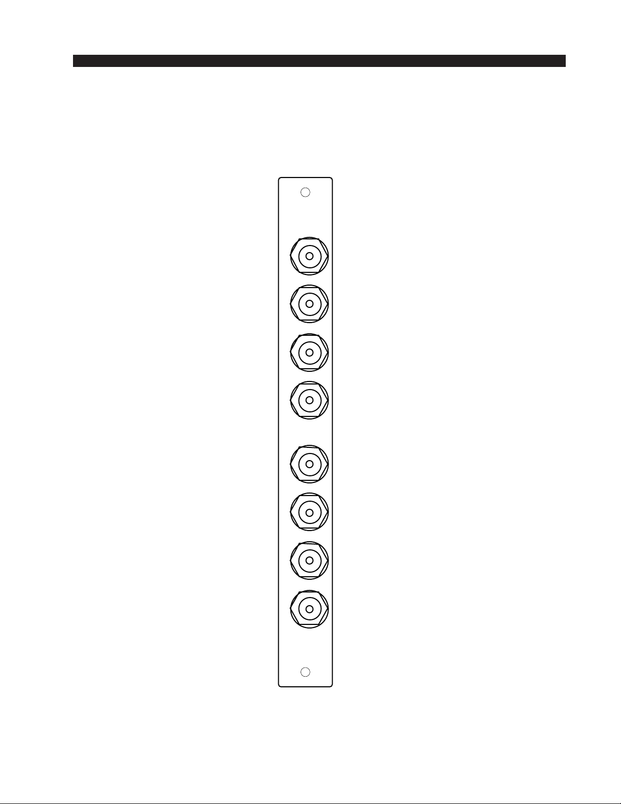
HARDWARE
I
I
I
I
I
I
I
I
8 BNC Panel
Digital Output Connections
use for 75 ohm AES-3 Id
1
based systems
AES1 OUT
AES2 OUT
AES3 OUT
AES4 OUT
AES5 OUT
AES6 OUT
H
SH
H
SH
H
SH
H
SH
75Ω
H
SH
H
SH
AES7 OUT
AES8 OUT
H
SH
H
SH
8
page 2 – 252001 / Jul 01
Page 48
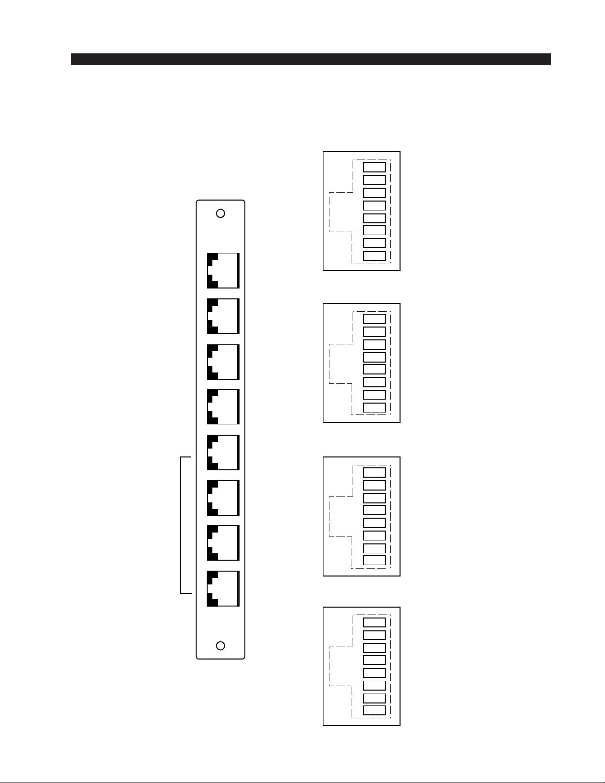
HARDWARE
8RJ Panel
Digital Output Connections
RJ-45 #1
AES 2 OUT HI
1
AES 2 OUT LO
2
3
AES 1 OUT HI
4
5
6
AES 1 OUT LO
1
RJ-45 #2
7
8
NOT USED
FOR
DIGITAL OUTPUT
CARD
1
2
3
4
5
6
7
8
RJ-45 #3
1
2
3
4
5
6
7
8
RJ-45 #4
AES 4 OUT H
AES 4 OUT LO
AES 3 OUT HI
AES 3 OUT LO
AES 6 OUT HI
AES 6 OUT LO
AES 5 OUT HI
AES 5 OUT LO
8
1
2
3
4
5
6
7
8
AES 8 OUT HI
AES 8 OUT LO
AES 7 OUT HI
AES 7 OUT LO
page 2 – 262001 / Jul 01
Page 49

HARDWARE
Analog Output Card (AO-2001)
Overview
Each Analog Output card provides 16 physical monaural output channels
. These output channels are configured in software to be any combination of
mono, stereo or 5.1 output signals. A Signal Definitions form in the supplied
XPoint software allows the user to set attributes for the output channels
including signal name, type, circuit #, etc. For example, the card may be
configured as 8 stereo outputs, or, 4 stereo outputs and 8 mono outputs. Many
combinations are possible up to the card’s 16 channel limit. Note that 5.1
signals may span across two AO-2001 output cards.
Each output card listens for connection commands from the CPU card
and then uses this information to connect the appropriate sources to their
selected output channels. The selected audio data is fed to 24 bit, twochannel digital-to-analog converters. D-A converter outputs are buffered by
integrated differential output drivers.
Analog Output Interface
Each balanced, unity gain output will drive loads up to 600Ω and behaves
much like a transformer in that either side of the balanced output may be
grounded. The analog outputs are direct coupled with an output impedance
of 50Ω and a nominal output signal level of +4dBu yielded from an analog
input signal of +4dBu (-20dBFs digital) .
Internal Programming Options
There are no internal programming options on the AO-2001 card.
page 2 – 272001 / Jul 01
Page 50
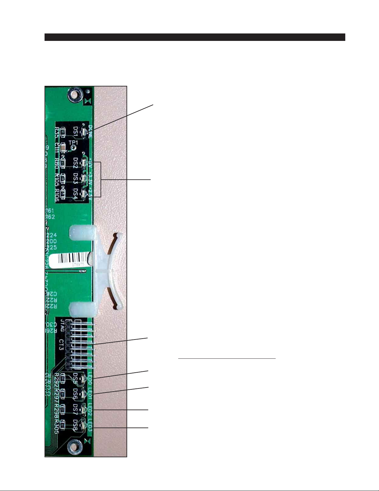
HARDWARE
Analog Output Card Status LED’s
DONE LED (DS1) - Normally OFF;
ON when programming the FPGA ,
Flashes when system clock is missing.
POWER SUPPLY STATUS (DS2-DS4) - ON indicates
power supply is OK.
JTAG HEADER - FPGA programming - factory use only.
AUXILIARY STATUS LED’s
ACTIVITY LED (DS5) - flashes on messages.
RACK ID DIPSWITCH (DS6) - ON = when SW1 pos.1 is ON,
otherwise OFF.
MUTE STATUS (DS7) - ON when the output channels
are muted.
CFG STATUS (DS8) - ON when card is not
configured.
page 2 – 282001 / Jul 01
Page 51
HARDWARE
Hook-Ups
All user wiring from the AO-2001 card takes place at the rear I/O
connectors modules (2DB and 8RJ). The 2DB module has two DB-25
connectors and 8RJ has eight RJ-45 connectors for audio output connections.
Upper DB-25—Analog Audio Connections
These include four (1-4) outputs. Pinout drawing on page 2-31 shows all
wiring connections at a glance.
Pin 24 – HI
Pin 12 – LO Channel 1 (Stereo 1 Lt) Out
Pin 25 – SH
Pin 10 – HI
Pin 23 – LO Channel 2 (Stereo 1 Rt) Out
Pin 11 – SH
Pin 21 – HI
Pin 9 – LO Channel 3 (Stereo 2 Lt) Out
Pin 22 - SH
Pin 7 – HI
Pin 20 – LO Channel 4 (Stereo 2 Rt) Out
Pin 8 – SH
Pin 18 – HI
Pin 6 – LO Channel 5 (Stereo 3 Lt) Out
Pin 19 – SH
Pin 4 – HI
Pin 17 – LO Channel 6 (Stereo 3 Rt) Out
Pin 5 – SH
Pin 15 – HI
Pin 3 – LO Channel 7 (Stereo 4 Lt) Out
Pin 16 – SH
Pin 1 – HI
Pin 14 – LO Channel 8 (Stereo 4 Rt) Out
Pin 2 – SH
Lower DB-25—Analog Audio Connections
These include four (5-8) outputs. Pinout drawing on pages 2-31 shows all
wiring connections at a glance.
Pin 24 – HI
Pin 12 – LO Channel 9 (Stereo 5 Lt) Out
Pin 25 – SH
Pin 10 – HI
Pin 23 – LO Channel 10 (Stereo 5 Rt) Out
Pin 11 – SH
Pin 21 – HI
Pin 9 – LO Channel 11 (Stereo 6 Lt) Out
Pin 22 - SH
page 2 – 292001 / Jul 01
Page 52
HARDWARE
Pin 7 – HI
Pin 20 – LO Channel 12 (Stereo 6 Rt) Out
Pin 8 – SH
Pin 18 – HI
Pin 6 – LO Channel 13 (Stereo 7 Lt) Out
Pin 19 – SH
Pin 4 – HI
Pin 17 – LO Channel 14 (Stereo 7 Rt) Out
Pin 5 – SH
Pin 15 – HI
Pin 3 – LO Channel 15 (Stereo 8 Lt) Out
Pin 16 – SH
Pin 1 – HI
Pin 14 – LO Channel 16 (Stereo 8 Rt) Out
Pin 2 – SH
8 RJ-45—Analog Audio Connections
Pinout drawing on pages 2-32 shows all wiring connections at a glance.
RJ-45#1 Pin 3 – HI
RJ-45#1 Pin 6 – LO
RJ-45#1 Pin 1 – HI
RJ-45#1 Pin 2 – LO
RJ-45#2 Pin 3 – HI
RJ-45#2 Pin 6 – LO
RJ-45#2 Pin 1 – HI
RJ-45#2 Pin 2 – LO
RJ-45#3 Pin 3 – HI
RJ-45#3 Pin 6 – LO
RJ-45#3 Pin 1 – HI
RJ-45#3 Pin 2 – LO
RJ-45#4 Pin 3 – HI
RJ-45#4 Pin 6 – LO
RJ-45#4 Pin 1 – HI
RJ-45#4 Pin 2 – LO
RJ-45#5 Pin 3 – HI
RJ-45#5 Pin 6 – LO
RJ-45#5 Pin 1 – HI
RJ-45#5 Pin 2 – LO
RJ-45#6 Pin 3 – HI
RJ-45#6 Pin 6 – LO
RJ-45#6 Pin 1 – HI
RJ-45#6 Pin 2 – LO
RJ-45#7 Pin 3 – HI
RJ-45#7 Pin 6 – LO
RJ-45#7 Pin 1 – HI
RJ-45#7 Pin 2 – LO
RJ-45#8 Pin 3 – HI
RJ-45#8 Pin 6 – LO
RJ-45#8 Pin 1 – HI
RJ-45#8 Pin 2 – LO
Channel 1 (Stereo1 Lt) Out
Channel 2 (Stereo 1 Rt) Out
Channel 3 (Stereo 2 Lt) Out
Channel 4 (Stereo 2 Rt) Out
Channel 5 (Stereo 3 Lt) Out
Channel 6 (Stereo 3 Rt) Out
Channel 7 (Stereo 4 Lt) Out
Channel 8 (Stereo 4 Rt) Out
Channel 9 (Stereo 5 Lt) Out
Channel 10 (Stereo 5 Rt) Out
Channel 11 (Stero 6 Lt) Out
Channel 12 (Stereo 6 Rt) Out
Channel 13 (Stereo 7 Lt) Out
Channel 14 (Stereo 7 Rt) Out
Channel 15 (Stereo 8 Lt) Out
Channel 16 (Stereo 8 Rt) Out
page 2 – 302001 / Jul 01
Page 53
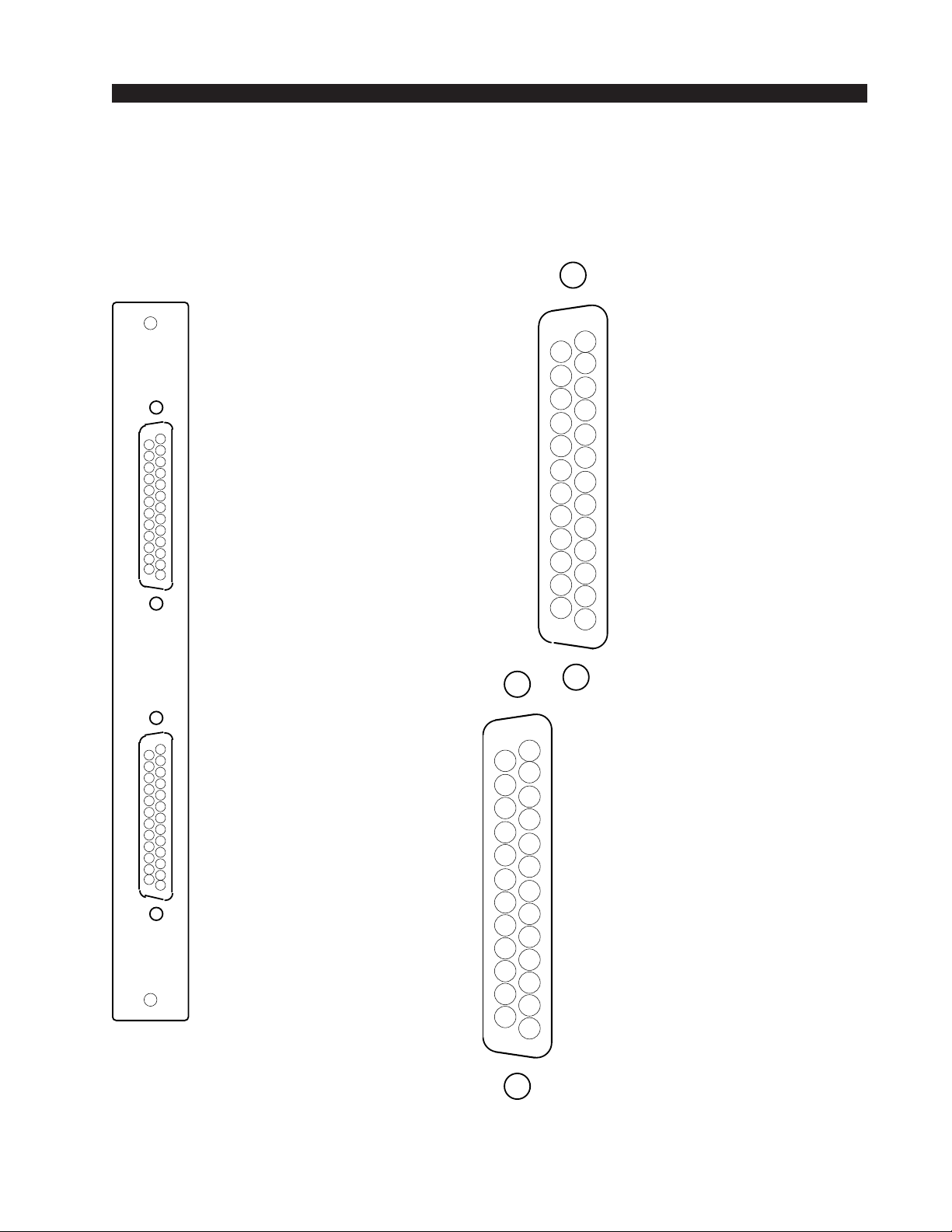
)
)
A
I/O PORTS
(Upper "A"
DB-25
HARDWARE
2DB Panel
Analog Output Connections
13
CHANNEL 1 (STEREO 1 LT) OUT SH
CHANNEL 1 (STEREO 1 LT) OUT HI
CHANNEL 2 (STEREO 1 RT) OUT LO
CHANNEL 3 (STEREO 2 LT) OUT SH
CHANNEL 3 (STEREO 2 LT) OUT HI
CHANNEL 4 (STEREO 2 RT) OUT LO
CHANNEL 5 (STEREO 3 LT) OUT SH
CHANNEL 5 (STEREO 3 LT) OUT HI
CHANNEL 6 (STEREO 3 RT) OUT LO
CHANNEL 7 (STEREO 4 LT) OUT SH
CHANNEL 7 (STEREO 4 LT) OUT HI
CHANNEL 8 (STEREO 4 RT) OUT LO
25
24
23
22
21
20
19
18
17
16
15
14
12
11
10
9
8
7
6
5
4
3
2
1
AUDIO GROUND
CHANNEL 1 (STEREO 1 LT) OUT LO
CHANNEL 2 (STEREO 1 RT) OUT SH
CHANNEL 2 (STEREO 1 RT) OUT HI
CHANNEL 3 (STEREO 2 LT) OUT LO
CHANNEL 4 (STEREO 2 RT) OUT SH
CHANNEL 4 (STEREO 2 RT) OUT HI
CHANNEL 5 (STEREO 3 LT) OUT LO
CHANNEL 6 (STEREO 3 RT) OUT SH
CHANNEL 6 (STEREO 3 RT) OUT HI
CHANNEL 7 (STEREO 4 LT) OUT LO
CHANNEL 8 (STEREO 4 RT) OUT SH
CHANNEL 8 (STEREO 4 RT) OUT HI
CHANNEL 9 (STEREO 5 LT) OUT SH
CHANNEL 9 (STEREO 5 LT) OUT HI
CHANNEL 10 (STEREO 5 RT) OUT LO
CHANNEL 11 (STEREO 6 LT) OUT SH
CHANNEL 11 (STEREO 6 LT) OUT HI
CHANNEL 12 (STEREO 6 RT) OUT LO
CHANNEL 13 (STEREO 7 LT) OUT SH
CHANNEL 13 (STEREO 7 LT) OUT HI
B
CHANNEL 14 (STEREO 7 RT) OUT LO
CHANNEL 15 (STEREO 8 LT) OUT SH
CHANNEL 15 (STEREO 8 LT) OUT HI
CHANNEL 16 (STEREO 8 RT) OUT LO
25
24
23
22
21
20
19
18
17
16
15
14
12
CHANNEL 9 (STEREO 5 LT) OUT LO
CHANNEL 10 (STEREO 5 RT) OUT SH
11
CHANNEL 10 (STEREO 5 RT) OUT HI
10
CHANNEL 11 (STEREO 6 LT) OUT LO
9
CHANNEL 12 (STEREO 6 RT) OUT SH
8
CHANNEL 12 (STEREO 6 RT) OUT HI
7
CHANNEL 13 (STEREO 7 LT) OUT LO
6
CHANNEL 14 (STEREO 7 RT) OUT SH
5
CHANNEL 14 (STEREO 7 RT) OUT HI
4
CHANNEL 15 (STEREO 8 LT) OUT LO
3
CHANNEL 16 (STEREO 8 RT) OUT SH
2
CHANNEL 16 (STEREO 8 RT) OUT HI
1
I/O PORTS
(Lower "B"
DB-25
page 2 – 312001 / Jul 01
AUDIO GROUND
13
Page 54
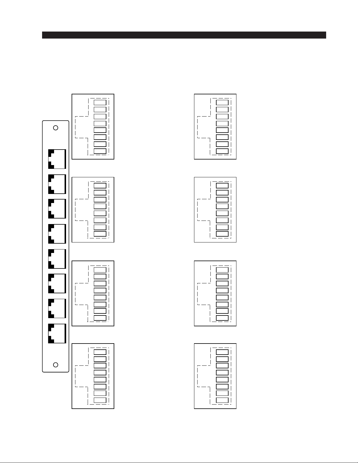
HARDWARE
8RJ Panel
Analog Output Connections
RJ-45 #1
CHANNEL 2 (STEREO 1 RT) OUT HI
1
CHANNEL 2 (STEREO 1 RT) OUT LO
2
3
4
5
6
1
7
8
CHANNEL 1 (STEREO 1 LT) OUT HI
CHANNEL 1 (STEREO 1 LT) OUT LO
RJ-45 #2
CHANNEL 4 (STEREO 2 RT) OUT HI
1
2
CHANNEL 4 (STEREO 2 RT) OUT LO
3
CHANNEL 3 (STEREO 2 LT) OUT HI
4
5
6
CHANNEL 3 (STEREO 2 LT) OUT LO
7
8
RJ-45 #3
RJ-45 #5
1
2
3
4
5
6
7
8
RJ-45 #6
1
2
3
4
5
6
7
8
RJ-45 #7
CHANNEL 10 (STEREO 5 RT) OUT HI
CHANNEL 10 (STEREO 5 RT) OUT LO
CHANNEL 9 (STEREO 5 LT) OUT HI
CHANNEL 9 (STEREO 5 LT) OUTLO
CHANNEL 12 (STEREO 6 RT) OUT HI
CHANNEL 12 (STEREO 6 RT) OUT LO
CHANNEL 11 (STEREO 6 LT) OUT HI
CHANNEL 11 (STEREO 6 LT) OUT LO
1
CHANNEL 6 (STEREO 3 RT) OUT HI
2
CHANNEL 6 (STEREO 3 RT) OUT LO
3
CHANNEL 5 (STEREO 3 LT) OUT HI
4
5
CHANNEL 5 (STEREO 3 LT) OUT LO
6
7
8
RJ-45 #4
8
1
CHANNEL 8 (STEREO 4 RT) OUT HI
2
CHANNEL 8 (STEREO 4 RT) OUT LO
3
CHANNEL 7 (STEREO 4 LT) OUT HI
4
5
CHANNEL 7 (STEREO 4 LT) OUT LO
6
7
8
RJ-45 #8
1
CHANNEL 14 (STEREO 7 RT) OUT HI
2
CHANNEL 14 (STEREO 7 RT) OUT LO
3
CHANNEL 13 (STEREO 7 LT) OUT HI
4
5
CHANNEL 13 (STEREO 7 LT) OUT LO
6
7
8
1
CHANNEL 16 (STEREO 8 RT) OUT HI
2
CHANNEL 16 (STEREO 8 RT) OUT LO
3
CHANNEL 15 (STEREO 8 LT) OUT HI
4
5
CHANNEL 15 (STEREO 8 LT) OUT LO
6
7
8
page 2 – 322001 / Jul 01
Page 55

HARDWARE
Host CPU (CPU-2001)
Overview
The host CPU card used in the Bridge 2001 incorporates a PC/104
computer mounted on a backplane interface card (the HC-2001 PCB). The
host computer utilizes RAM, a flash disk (which emulates a standard IDE
hard drive) and an Ethernet port. There is no hard disk drive. Keyboard,
floppy controller and video ports are for factory use only. The host CPU board
must only be present in the “master chassis” of a single tier switch.
The purpose of the CPU card is to provide control of the 2001 system
including the master chassis and any other chassis connected via Stacking or
Audio Network cards. The CPU communicates to the XPoint Configuration
PC and XY Controller GUI’s via TCP/IP over Ethernet, via a backplane
command bus to the other cards in its switch, and via RS-485 serial links to
existing XY Controllers and Wheatstone consoles. The CPU also phase locks
the crosspoint switch and attached remote racks to an on board crystal
oscillator or an external AES “black” reference source.
Hardware and software configuration as well as real time crosspoint
information is saved in non-volatile storage on the CPU card and is restored
at power up or reset. This configuration information provides details to the
host application running on the CPU such as the specific audio hardware
available, serial port allocation, I/O signal names, etc. and may be modified
via the Configuration GUI. Switching information is dynamically controlled
via both hardware based XY Controllers and PC based XY GUI’s. Network
IP address configuration of the CPU is handled by the provided DOS utility
application Networkconfig.exe. System configuration is discussed in detail in
the following sections.
Multi CPU / Failover CPU Systems
Multiple CPU’s may optionally be present in large “Multi-Tier” configurations. For the sake of clarity, a single CPU system is assumed in this
discussion. Please consult the factory for multi-cpu system details. S
A
PPENDIX
“2”
FOR DETAILS ON FAILOVER
CPU
OPERATION
.
CPU-2001 BIOS Settings/Format
BIOS Setup and formatting of the Host CPU is completed prior to the
testing of your 2001 Switch at the Wheatstone factory. There are no user
adjustable settings. Please contact customer support with questions regarding the PC/104 SBC BIOS settings or flash disk formatting.
2001 / Jul 01
EE
page 2 – 33
Page 56
HARDWARE
Ethernet IP Addressing
Wheatstone 2001 digital audio network routers ship with the host CPU IP
address set for 192.168.1.160 and the personal computer’s NIC set for
192.168.1.212. Stand-alone systems (not interfaced to a station’s existing
network) require no IP address changes.
Before the switch will be recognized on your network, you will most likely
need to re-configure the host CPU and XPoint PC’s IP addresses. To change
the host CPU IP address, a utility application, NETWORKCONFIG.EXE,
supplied on the XPoint CD-ROM must be run. See the Appendix 1 for detailed
information.
Ethernet Interface Wiring
Stand-alone systems are defined as a host rack connected to a XPoint
configuration PC and not interfaced to a station’s existing network. Standalone systems are “point to point” configurations and are connected by a CAT5 crossover cable.
Networked systems are defined as a host rack connected directly to an
existing Ethernet network hub. Networked systems are connected to the
network hub via a straight (pin to pin) CAT-5 cable. Typical CAT-5 cable pinouts are included in the “Hook Ups” section near the end of this
CHAPTER
.
Internal Programming Options
All internal programming options are made via PCB mounted dipswitches
and jumpers. Dipswitches and jumpers setting shown in the table below:
CPU (HC-2001A PCB)
NAME REF.DES. DEFAULT
RACK-ID
48H_44.1L
AUTODETECT SW8 pos1 ON
CPU_RESET
MSR_SELECT
485_A_TERM
485_B_TERM
RS-232 GND
AGND to DGND
SW7
J6
SW5
SW9
SW1, SW2
SW3, SW4
J1
J4
0000 (ALL OFF)
OPEN
OPEN
OPEN
BIAS TERMINATION
BIAS TERMINATION
OPEN for 485
OPEN
page 2 – 342001 / Jul 01
Page 57
HARDWARE
Switch Settings
DIPSW1-SW4 RS-485 Termination
These four, 4-position dipswitches configure the 485 port termination as
follows:
SW1-SW4
POSITION BIASED TERM PASSIVE TERM UNTERMINATED
1 - TX10Ω
2 - TX+
3 - TX4 - 120Ω
Choices are Unterminated, Normal Termination, or BIAS Termination on
the transmit and receive lines. SW1 and SW2 are for Port A, and SW3 and
SW4 are for Port B. SW1 and SW3 are for the RS-485 transmitter’s
termination on the CPU; SW2 and SW4 are for receiver terminations.
An RS-485 bus may only be BIAS TERMINATED at one end. All
applicable Bridge 2001 OAN and CPU cards are set for BIAS TERMINATION by default. All peripheral devices are set for NO TERMINATION by
default. Set the TERMINATION to ON for the last controller or console only,
in a RS-485 chain.
FUNCTION
ON=10Ω BYPASS
ON=750Ω PULLUP
ON=750Ω PULLDOWN
ON=120Ω PARALLEL
OFF*
ON*
ON*
ON*
ON
OFF
OFF
ON
OFF
OFF
OFF
OFF
SW5 - CPU RESET
This momentary pushbutton switch allows CPU to be reset without power
down of system. Holding for two seconds will cause the FPGA to be
reprogrammed also.
DIPSW6 - Utility Switches
Pos.1 - DIP4 - not used
Pos.2 - DIP5 - not used
Pos.3 - C6 - not used
Pos.4 - C7 - not used
DIPSW7 - Rack ID
Default is all OFF (Rack ID 1, binary ØØØØ) for a master rack CPU.
Note: Rack ID numbers are coded in binary.
Rack ID 1 equals binary Ø‚ Rack ID 2 equals binary 1, etc.
Rack ID’s are set at the factory. Incorrect setting of these switches can cause
system malfunction.
DIPSW8
Pos.1 - Autodetect - default is “ON”
Autodetect will sense the presence of an external AES input clock and
slave the system to this AES reference. If the AES reference fails (wire breaks,
2001 / Jul 01
2001 / Apr 03
page 2 – 35
Page 58

HARDWARE
etc.) the system will revert to onboard crystal reference until AES input
returns. Autodetect disabled forces system to ignore AES reference and
always use the onboard crystal and bypass PLL.
Pos.2 - not used
Pos.3 - not used
Pos.4 - not used
SW9 - Master Select
This momentary pushbutton switch may be used to command transfer
of CPU mastering from one CPU to other in a dual CPU system.
Jumper Settings
J1 - RS-232 GND - default is “OPEN”
J1 is inserted if Port A is to be used as a RS-232 port rather than RS-
485. The jumper shorts DB-9 connector Pin 8 to ground which must be
used for the RS-232 ground reference.
J2 - not used
J3 - not used
J4 - AGND to DGND - default is “CLOSED”
J4 connects Audio Ground to Digital Ground.
J5 - FPGA PGM - momentary shorting will reprogram the FPGA.
J6 - 48 or 44.1kHz Sample Rate Select*
Selects 48kHz or 44.1 kHz as Master Fs; derived from onboard crystal
oscillators.
J6 open - 48 kHz
J6 shunted - 44.1 kHz
Serial Interface Ports
Serial ports A and B are typically used to connect remotely located XY
controllers and Wheatstone consoles to the switch via 4-wire RS-485.
These ports are configured from the Xpoint GUI and are setup at the
factory as follows:
PORT A - RS-485, 38400 bps, XY controller port
PORT B - RS-485, 9600 bps, Console port
Note: Serial port A may be setup for RS-232 operation via jumper setting
J1.
*NOTE: When changing the audio sample rate of the Bridge
2001 Digital Audio Network
Router, changes must be made
in the following places: DO-2001
Digital Output Card, CPU-2001
Host CPU, OAN-2001 Audio
Network Card, CEX-2001 Stacking Card, and QAT-2001 Quad
Audio Network Card. See the
appropriate manual sections for
details.
2001 / Jul 01
2001 / Mar 05
page 2 – 36
Page 59
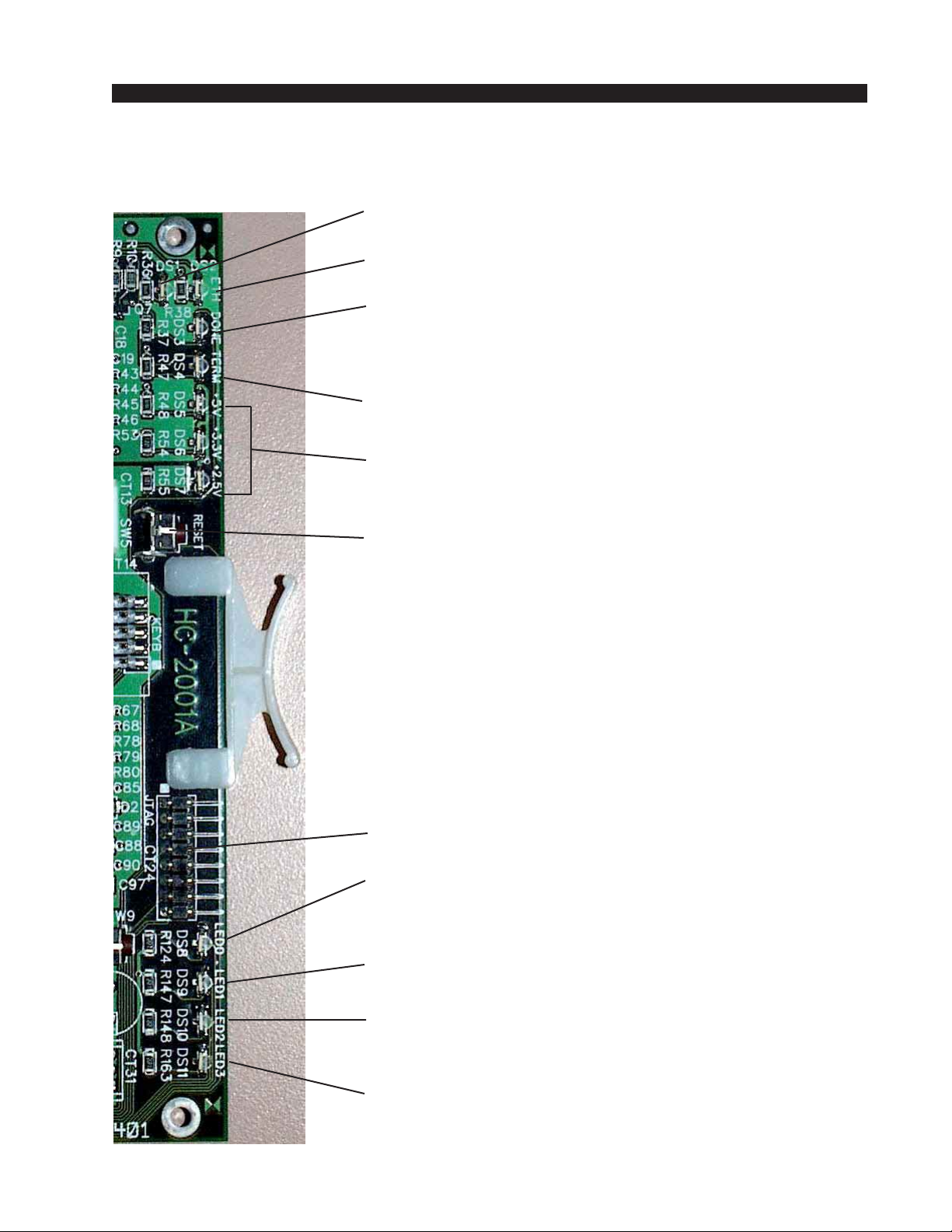
HARDWARE
CPU Card Status LED’s
ETHERNET ACTIVITY (DS1) - ON indicates TCP/IP
activity.
ETHERNET LINK (DS2) - ON indicates Ethernet
is link OK.
DONE LED (DS1) - Normally OFF;
ON when programming the FPGA,
Flashes when system clock is missing.
BACKPLANE TERM FAULT (DS4) - lights on termination
fault.
POWER SUPPLY STATUS (DS5-DS7) - ON indicates
power supply is OK.
RESET SWITCH (SW5) - momentary pushbutton. Hold for
2 seconds for complete reset of
CPU and FPGA.
JTAG HEADER - FPGA programming - factory use only.
BACKPLANE RESPONSE (DS8) - lights if the CPU is not
responding to backplane
messages.
CLOCK PHASE (DS9) - ON indicates that the EXT AES
ref is out of phase (unlocked).
BUFFER OVERFLOW (DS10) - ON indicates buffer
problem. Contact support
or reset system.
CLOCK MASTER (DS11) - ON indicates CPU is driving
backplane clock.
page 2 – 372001 / Jul 01
Page 60

HARDWARE
Hook-Ups
All user wiring to and from CPU card takes place at the rear I/O connector
module (PWIH-2001) that plugs into the extreme left-hand slot (if you are
looking at the rear of the cage). There are three DB-9 female serial interface
connectors, one RJ-45 Ethernet connector and two power supply connectors.
Pinout drawing on page 2-40 shows all wiring connections at a glance.
L
EFT
“A” DB-9—S
PIN 5 – AES SYNC OUT SH
P
IN
4 – AES SYNC OUT HI NOT U
PIN 9 – AES SYNC OUT LO
P
IN
3 – RX1 HI (RS-485)
P
IN
8 – RX1 LO (RS-485) / GND (RS-232)
P
IN
2 – TX (RS-232)
P
IN
7 – RX (RS-232)
P
IN
1 – TX1 HI (RS-485)
P
IN
6 – TX1 LO (RS-485)
ERIAL INTERFACE
P
ORT
SED
1 C
ONNECTIONS
R
IGHT
“B” DB-9—S
PIN 5 – AES SYNC IN SH
P
IN
PIN 9 – AES SYNC IN LO
P
IN
P
IN
P
IN
P
IN
P
IN
P
IN
L
OWER
“C” DB-9—AES SYNC P
PIN 5 – AES SYNC IN SH
P
IN
P
IN
P
IN
P
IN
P
IN
RJ-45—E
PIN 1 – TXD +
P
IN
P
IN
P
IN
P
IN
P
IN
P
IN
P
IN
ERIAL INTERFACE
P
4 – AES SYNC IN HI NOT U
3 – RX2 HI (RS-485)
8 – RX2 LO (RS-485)
2 – N/C
7 – N/C
1 – TX2 HI (RS-485)
6 – TX2 LO (RS-485)
ORT CONNECTIONS
4 – AES SYNC IN HI
9 – AES SYNC IN LO
2 – AES SYNC OUT SH
1 – AES SYNC OUT HI
6 – AES SYNC OUT LO
THERNET
C
ONNECTIONS
2 – TXD 3 – RXD +
4 – N/C
5 – N/C
6 – RXD -
7 – LN LED
8 – LK LED
ORT
SED
2 C
ONNECTIONS
2001 / Jul 01
2001 / Nov 02
page 2 – 38
Page 61
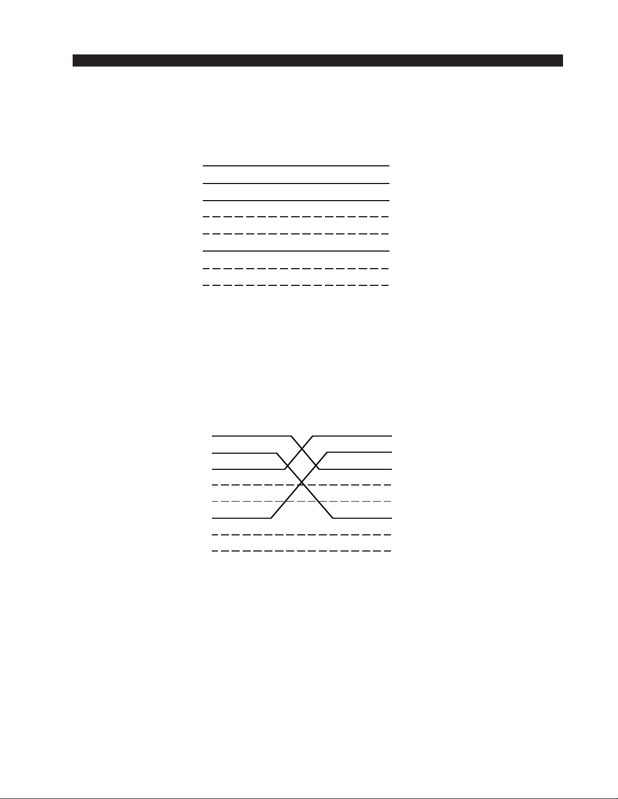
HARDWARE
/C
/C
/CN/C
/C
/C
/CN/C
/C
/C
/CN/C
T
PIN
White/Orange
Orange
RJ-45
Plug
White/Green
Blue
White/Blue
Green
White/Brown
Brown
U
SED FOR CONNECTING THE HOST
T
YPICAL
1
2
3
4
5
6
7
8
YPICAL
E
THERNET
TXD +
TXD RXD +
N
RXD N
N
CPU
C
MODULE TO YOUR NETWORK HUB
ROSSOVER
C
ABLE
C
PIN
ABLE
White/Orange
1
Orange
2
White/Green
3
Blue
4
White/Blue
5
Green
6
White/Brown
7
Brown
8
RJ-45
Plug
.
PIN
White/Orange
Orange
RJ-45
Plug
U
SED FOR SIMPLE “POINT TO POINT” CONNECTIONS BETWEEN THE SUPPLIED
C
ONFIGURATION
White/Green
Blue
White/Blue
Green
White/Brown
Brown
PC’S NIC
TXD +
1
TXD -
2
RXD +
3
4
N
5
RXD -
6
N
7
N
8
CARD AND THE
HOST CPU
RXD +
RXD -
TXD +
N
TXD N
N
MODULE
PIN
White/Green
1
Green
2
White/Orange
3
Blue
4
White/Blue
5
Orange
6
White/Brown
7
Brown
8
.
RJ-45
Plug
XP
page 2 – 392001 / Jul 01
Page 62
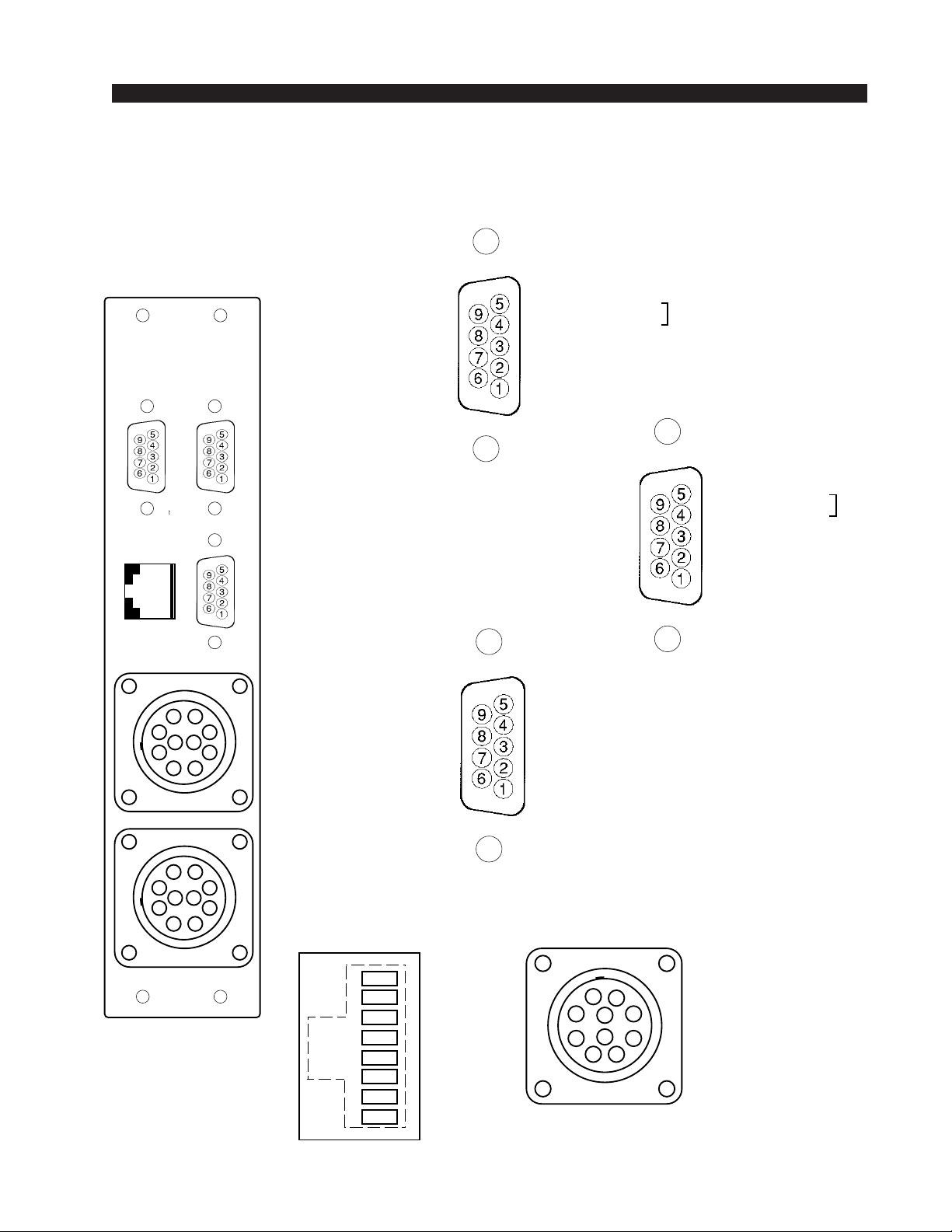
HARDWARE
r
A
B
C
D
E
F
G
H
I
J
L
R
T
PWIH Panel
I/O Connections
(Left"A" DB-9)
I/O PORTS
SERIA
AB
ETHE
NE
C
NOT
- AES SYNC OUT LO
USED
*
RX1 LO (RS-485)
RX (RS-232)
TX1 LO (RS-485)
*
This pin is
RS-232 GND when
J1 is installed on CPU
I/O PORTS
(Lower "C" DB-9)
AES SYNC IN LO
AES SYNC OUT LO
N/C
N/C
AES SYNC OUT SH
AES SYNC OUT HI
RX1 HI (RS-485)
TX (RS-232)
TX1 HI (RS-485)
NOT
- AES SYNC IN LO
USED
RX2 LO (RS-485)
TX2 LO (RS-485)
AES SYNC IN SH
AES SYNC IN HI
N/C
AES SYNC OUT SH
AES SYNC OUT HI
N/C
NOT
USED
I/O PORTS
(Right "B" DB-9)
AES SYNC IN SH
AES SYNC IN HI
RX2 HI (RS-485)
N/C
TX2 HI (RS-485)
NOT
USED
Ethernet
POWER SUPPLY
CONNECTOR
A) AUDIO COMMON
B) + 16V
C) - 16V
D) DIGITAL COMMON
E) N/C
F) DIGITAL COMMON
G) + DIGITAL
H) + DIGITAL
I) N/C
J) N/C
page 2 – 40
2001 / Jul 01
2001 / Nov 02
PWR
Connecto
(RJ-45)
1
2
3
4
5
6
7
8
TXD +
TXD -
RXD +
N/C
N/C
RXD -
LN LED
LK LED
Page 63
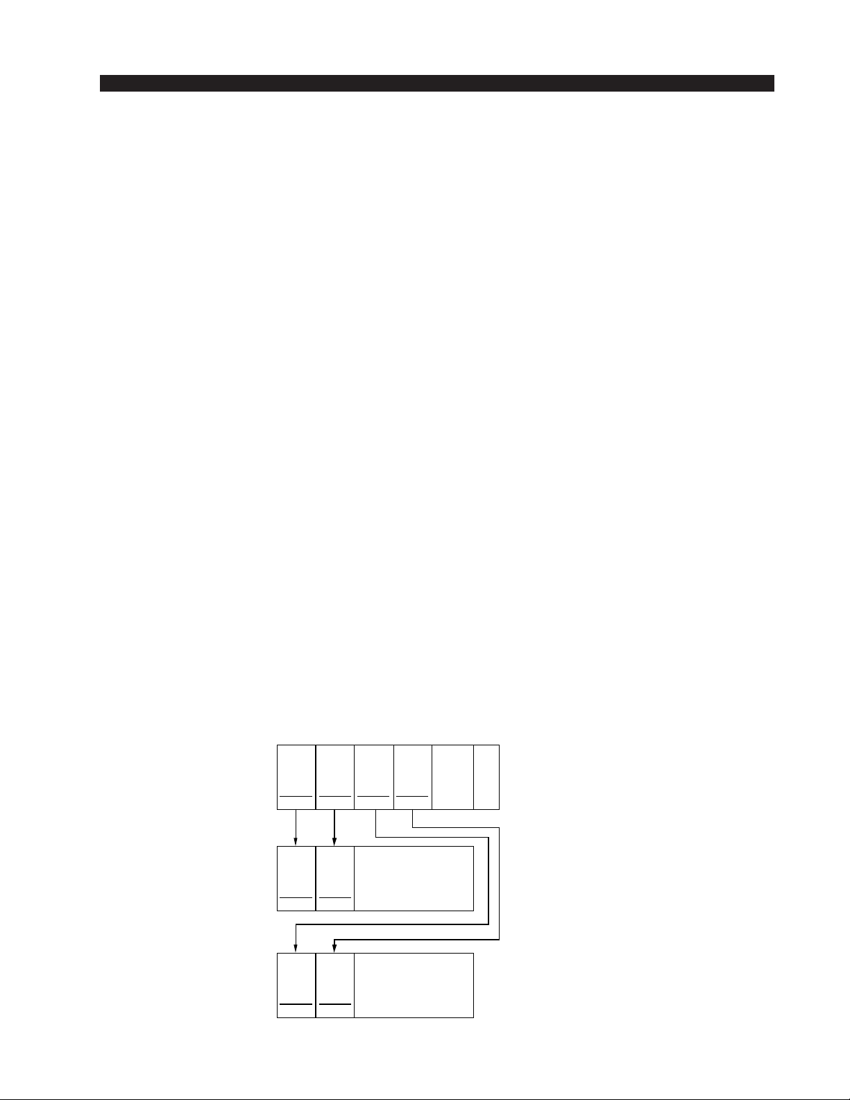
HARDWARE
Audio Network Card
(OAN-2001)
Overview
The Audio Network card is used to connect a master chassis to a remote
chassis via a fiber optic link or CAT-5 cable. Audio Network cards must be
installed in pairs (i.e. an Audio Network card in the master chassis communicates to a companion Audio Network card in the remote chassis). An
Audio Network card selects up to 64 mono channels (32 stereo signals), in
four blocks of 16 channels, for bi-directional transport to the companion
Audio Network card. The companion Audio Network card in turn may place
these channels onto the appropriate number of consecutive remote chassis
TDMs (1-4, depending on the number of channels). The CPU card controls
the configuration of the Audio Network cards (local channels being driven
to the remote Audio Network card / TDMs being driven by the remote Audio
Network card).
Between local and remote racks within a single tier, Audio Network
cards are used to bring data in from and send data out to remote racks. No
provision is made to configure Input and Output cards in a remote chassis
to communicate directly with each other. The remote racks are similar to the
local chassis; with up to 4 TDMs populated per Audio Network card. A
remote chassis cannot be daisy chained to another remote chassis.
In a Multi-Tiered environment, Audio Network cards are used as the
inter-connections between the Hub switch and up to 14 Satellite switches.
These “inter-connect” Audio Network cards must all reside in the local racks
of each tier. In addition, at least one of these inter-connecting Audio
Network cards must reside in the master chassis of each satellite tier (in order
to drive the clock).
LOCAL
REMOTE
REMOTE
OAN
#1
LOCAL
PRI
OAN
#1
REMOTE
PRI
OAN
#n
REMOTE
PRI
OAN
#2
LOCAL
SEC
OAN
#2
REMOTE
SEC
OAN
#n
REMOTE
SEC
OAN
#3
LOCAL
PRI
OAN
#4
LOCAL
SEC
RACK
ID5
RACK
IDn
RACK
ID1
C
P
U
MASTER
RACK
REMOTE
CHASSIS
#1
REMOTE
CHASSIS
#n
page 2 – 412001 / Jul 01
Page 64
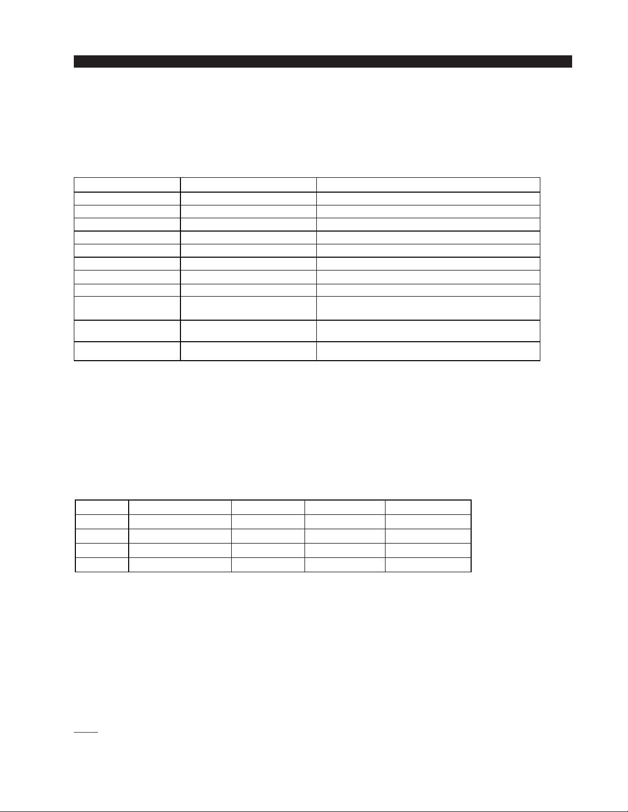
HARDWARE
Internal Programming Options
All internal programming are made via PCB mounted dipswitches.
Dipswitch settings are shown in the table below:
OAN-2001 PCB
NAME REF.DES.
RACK-ID
LOCAL/REMOTE
SECONDARY/PRIMARY
SAMPLE RATE
MEDIA
485_A_TERM
485_B_TERM
BPSCR J1
CLOCK ENABLE J3
SOCKETED CLOCK
ENABLE
RESET J2, J4 = not installed
SW7
SW5 pos. LOCAL/REMOTE
SW5 pos. SECONDARY/PRIMARY
SW5 pos. 48kHz / 44kHz
SW5 pos. FIBER / CAT 5
SW1, SW3
SW2, SW4
J5
see Breakout Table - DIPSW7 Rack ID
LOCAL=OFF
SECONDARY=OFF
48kHz=OFF
FIBER=OFF
see Breakout Table - DIPSW1-4 485 Termination
see Breakout Table - DIPSW1-4 485 Termination
ALWAYS SHORTED ETHERNET MODE SETTING
OPEN=Y1&Y2
DISABLED
GRN=DISABLED
SHORT=RESET
REMOTE=ON
PRIMARY=ON
44.1kHz=ON
CAT5=ON
SHORT PINS 1&2=Y1 ENABLED
SHORT PINS 2&3=Y2 ENABLED
SHORT PINS 1&2=Y3 ENABLED
Switch Settings
DIPSW1-SW4 - 485 Termination
SW1-SW4
POSITION BIASED TERM PASSIVE TERM UNTERMINATED
1 - TX10Ω
2 - TX+
3 - TX4 - 120Ω
These four 4-position dipswitches configure the 485 port termination as
follows:
Choices are Unterminated, Normal Termination, or BIAS Termination
on the transmit and receive lines. SW1 and SW2 are for Port A, and SW3 and
SW4 are for Port B. SW1 and SW3 are for the RS-485 transmitter’s
termination; SW2 and SW4 are for receiver terminations.
An RS-485 bus may only be BIAS TERMINATED at one end. All
applicable Bridge 2001 OAN and CPU cards are set for BIAS TERMINATION by default. All peripheral devices are set for NO TERMINATION by
default. Set the TERMINATION to ON for the last controller or console
only, in a RS-485 chain.
FUNCTION
ON=10Ω BYPASS
ON=750Ω PULLUP
ON=750Ω PULLDOWN
ON=120Ω PARALLEL
OFF*
ON*
ON*
ON*
ON
OFF
OFF
ON
OFF
OFF
OFF
OFF
* Default
page 2 – 422001 / Jul 01
Page 65

HARDWARE
applicable Bridge 2001 OAN and CPU cards are set for BIAS TERMINATION by default. All peripheral devices are set for NO TERMINATION
by default. Set the TERMINATION to ON for the last controller or
console only, in a RS-485 chain.
DIPSW5
Pos.1 - Local/Remote (Clock source)
The Local/Remote setting is required to configure OAN cards such
that a Local card will operate from the backplane clock/sync references.
A Remote card would likewise infer that clock/sync are to be extracted
from Fiber/CAT5 and driven onto backplane.
• The system’s master chassis must have only one LOCAL-PRIMARY
OAN card connected to each companion remote chassis.
• Each remote chassis must have only one REMOTE-PRIMARY
OAN card.
Pos.2 - Secondary/Primary
Some system configurations may have multiple OAN cards in each
rack. The Primary setting is used to distinguish which OAN card will act
as the Clock/Sync master in the Remote chassis. Additional OAN cards
must be set to Secondary. Secondary cards will not transmit/receive
control information since this would duplicate the Primary card.
• The system’s master chassis must have only one LOCAL-PRIMARY
OAN card connected to a companion remote chassis.
• Each remote chassis must have only one REMOTE-PRIMARY
OAN card.
Pos.3 - 48kHz / 44.1kHz*
Selects the system’s sample rate frequency; 48 or 44.1 kHz.
If Y1 and Y2 are populated with surface mount clock oscillators, and
Y3 is not installed (default), then 3 pin jumper posts J3 must be used to
select the correct frequency. A jumper shunt between the center pin and
pin closest to Y1 selects Y1 (48 kHz) and likewise a shunt to pin closest
to Y2 selects Y2 (44.1 kHz).
The clock oscillator on the Audio Network card must match the
system’s master clock frequency. If the system audio sample rate is 48
kHz, then the clock reference must be 24.576 MHz and likewise for 44.1
kHz, a 22.5792 MHz clock is necessary. If only Y3, a DIP socketed clock
is populated and not Y1 or Y2, then the appropriate matching clock
frequency must be installed in Y3.
Pos.4 - Fiber/CAT5
Selects whether the audio network connection to the companion Audio
Network card will be made through either optical fiber or copper CAT-5
cable.
*NOTE: When changing the audio sample rate of the Bridge
2001 Digital Audio Network
Router, changes must be made
in the following places: DO-2001
Digital Output Card, CPU-2001
Host CPU, OAN-2001 Audio
Network Card, CEX-2001 Stacking Card, and QAT-2001 Quad
Audio Network Card. See the
appropriate manual sections for
details.
2001 / Jul 01
2001 / Mar 05
page 2 – 43
Page 66
HARDWARE
DIPSW7 - Rack ID
If the OAN card is a Remote-Primary Audio Network Card, this OAN
card must supply the Rack ID to its backplane from the 4 bit onboard switch.
Remote Rack ID’s must be 5 or higher.
SW7 RACK ID
SW7
ON
ON ON
OFF
MASTER CPU
RESERVED
FOR
STACKING
USED FOR
AUDIO
NETWORK
CHASSIS
RACK ID
1
2
3
4
5
6
7
8
9
10
11
12
13
14
15
16
RACK ID8
OFF OFF OFF OFF
OFF OFF OFF ON
OFF OFF
OFF OFF ON ON
OFF ON OFF OFF
OFF ON OFF ON
OFF
OFFONONON
ON OFF OFF OFF
ON OFF OFF ON
ON OFF ON OFF
ON OFF ON ON
ON ON OFF OFF
ON ON
ON ON ON OFF
ON ON ON ON
RACK ID4 RACK ID2 RACK ID1
OFF
OFF
ON
• Each remote chassis must have only one REMOTE-PRIMARY OAN
card.
Note: Rack ID numbers are coded in binary: Rack ID 1 equals binary Ø‚ Rack
ID 2 equals binary 1, etc.
Rack ID’s are set at the factory. Incorrect setting of these switches can cause
system malfunction.
Jumper Settings
J1 - Ethernet Mode Setting
Always shorted.
J2 - Reset
Momentary shorting does a complete reset.
page 2 – 442001 / Jul 01
Page 67

HARDWARE
J3, J5 - Clock Selection
OAN cards are designed to have two clock options - surface mounted
crystals, or a socketed crystal. Surface mount crystals can be used without
crystal in socket - just short the pins closest to the desired crystal (J3) to
enable it. Or insert the desired crystal into the socket and enable it by shorting
the enable line (J5) to the crystal.
If Y1 and Y2 are populated with surface mount clock oscillators, and Y3
is not installed (default), then 3 pin jumper posts J1 must be used to select
the correct frequency. A jumper shunt between the center pin and pin closest
to Y1 selects Y1 (48 kHz) and likewise a shunt to pin closest to Y2 selects
Y2 (44.1 kHz).
J4 - Reset - not used
page 2 – 452001 / Jul 01
Page 68
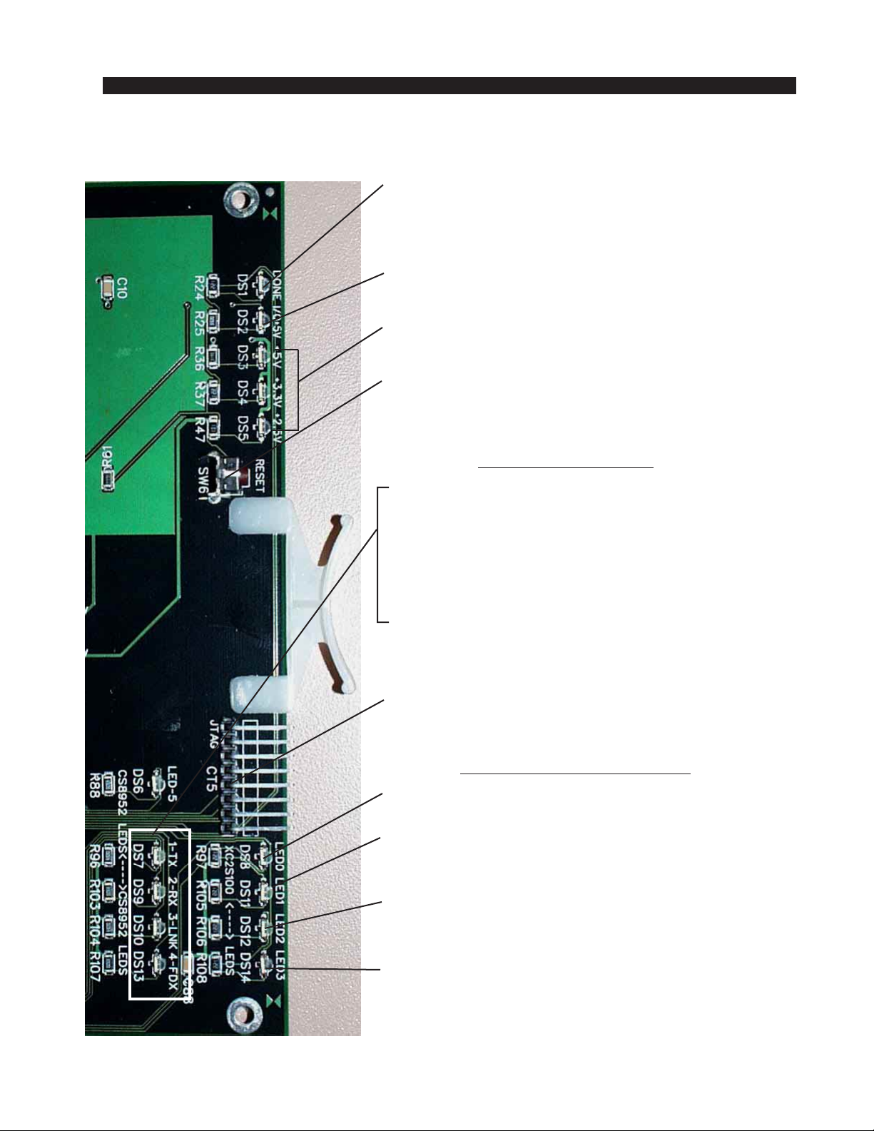
HARDWARE
OAN Card Status LED’s
DONE LED (DS1) - Normally OFF;
ON when programming the FPGA,
Flashes when system clock is missing.
I/O INTERFACE (DS2) - lights when the rear
panel card is powered.
POWER SUPPLY STATUS (DS3-DS5) -
ON indicates power supply is OK.
RESET SWITCH (SW6) - momentary pushbutton.
Resets the OAN card.
LINK STATUS LED’s
TX STATUS (DS7) - ON indicates that the data
transmission link is OK.
RX STATUS (DS9) - ON indicates that the data
receive link is OK.
LINK STATUS (DS10) - ON indicates that a hardware
link is established.
FULL DUPLEX (DS13) -ON indicates that the link is
in full duplex mode.
JTAG HEADER - FPGA programming - factory use only.
AUXILIARY STATUS LED’s
ACTIVITY LED (DS8) - flashes on messages.
CLOCK MASTER (DS11) - ON indicates that this OAN
card supplies the backplane clock.
COMM ERROR (DS12) - Normally OFF.
ON for errors.
CFG/BUFFER ERROR (DS14) - Normally OFF.
Flashes when the card is not configured.
Once configured, the LED indicates buffer errors.
page 2 – 462001 / Jul 01
Page 69

HARDWARE
/CN/C
/CN/C
/CN/CN/CN/C
Hook-Ups
All user wiring to and from OAN-2001 Card takes place at the rear I/O
connector module (ONI-2001). CAT5 or multi-mode optical fiber Audio
Network connections to companion OAN cards are made via RJ-45 or SC type
optical connectors. There are also two female DB-9 serial port connectors for
use as RS-485/RS232 communication links to Wheatstone consoles and XY
controllers. Pinout drawing on page 2-49 shows all wiring connections at a
glance.
Upper “A” DB-9—Serial Interface Port 1 Connector
Pin 3 – RX1 HI (RS-485)
Pin 8 – RX1 LO (RS-485)
Pin 1 – TX1 HI (RS-485)
Pin 6 – TX1 LO (RS-485)
Pin 2 – TX1 (RS-232)
Pin 7 – RX1 (RS-232)
Pin 5 - GND
Lower “B” DB-9—Serial Interface Port 2 Connector
Pin 3 – RX2 HI (RS-485)
Pin 8 – RX2 LO (RS-485)
Pin 1 – TX2 HI (RS-485)
Pin 6 – TX2 LO (RS-485)
Pin 2 – TX2 (RS-232)
Pin 7 – RX2 (RS-232)
Pin 5 - GND
RJ-45—CAT5 Audio Network Connector
Pin 1 – TXD +
Pin 2 – TXD Pin 3 – RXD +
Pin 4 – N/C
Pin 5 – N/C
Pin 6 – RXD -
Pin 7 – N/C
Pin 8 – N/C
CAT5 Crossover Cable for OAN to OAN Connections
RJ-45
Plug
White/Orange
Orange
White/Green
Blue
White/Blue
Green
White/Brown
Brown
PIN
TXD +
1
TXD -
2
RXD +
3
4
N
5
RXD -
6
N
7
8
RXD +
RXD -
TXD +
TXD N
PIN
White/Green
1
Green
2
White/Orange
3
Blue
4
White/Blue
5
Orange
6
White/Brown
7
Brown
8
RJ-45
Plug
page 2 – 472001 / Jul 01
Page 70
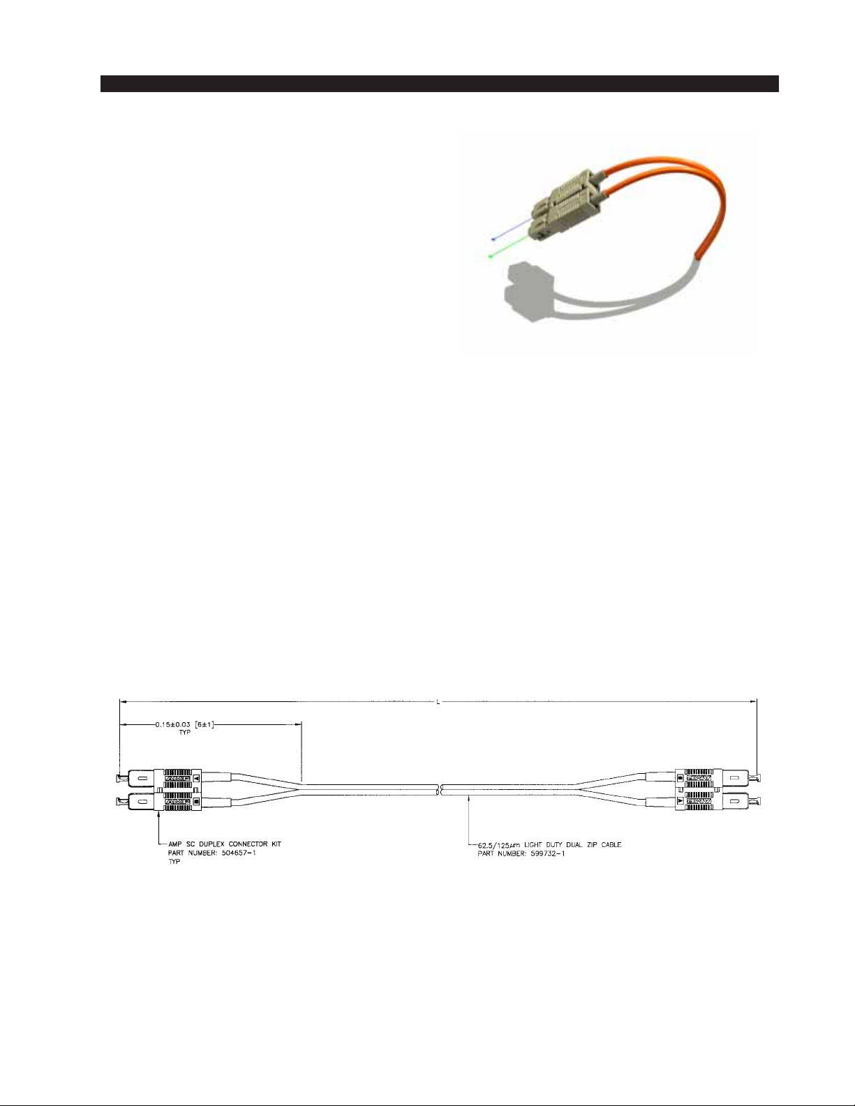
HARDWARE
Optical Fiber Interface
Connector Type
The OAN audio network card provides a
SC Duplex style connector for interfacing
optical fiber. The SC (subscription channel)
connector is a low insertion loss, locking
mechanism with excellent strain relief characteristics. The following AMP® part number may be used to reference the physical
characteristics of the required mating connector.
AMP SC Duplex connector Kit Part Number: 504657-1
Optical Fiber
The typical optical fiber cable required in this application is a
multimode, glass core cable, with a core/cladding size of 62.5/125
µ
suitable for low-to-moderate-speed data links (≤100Mbps). The fullduplex nature of the audio network interface requires one fiber for
transmit, and one for receive; hence dual zip cables are recommended.
m,
Optical fiber cables are manufactured with a variety of jacket
materials, which directly affect cable cost, including Thermoplastic
Elastomer (TPE), Kynar® and Teflon® FEP. Physical properties of the
jacket material determine a cable’s resistance to abrasions, flame
retardancy, etc. Check local codes to be sure the cable you plan on
using is compliant in your application.
DIMENSIONS IN [ ] ARE IN INCHES.
page 2 – 482001 / Jul 01
Page 71
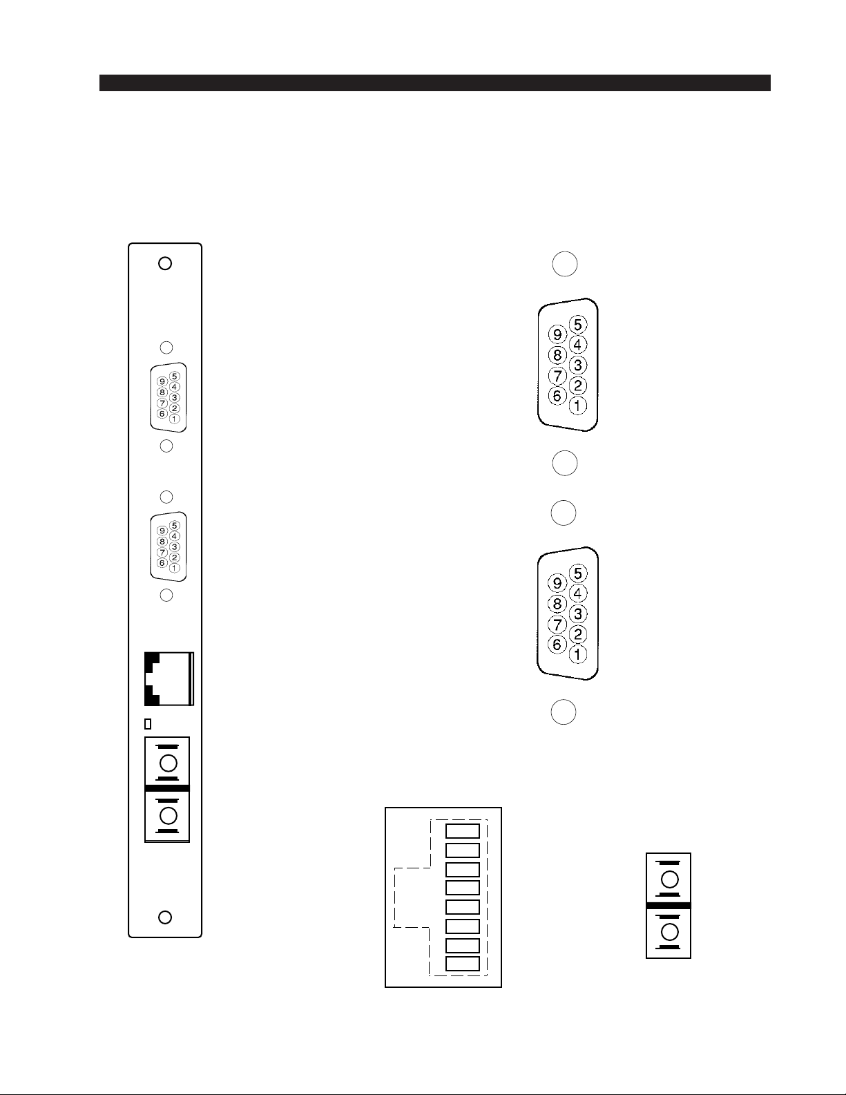
SERIAL
+
-
+
-
A
B
I/O Connections
I/O PORTS
(Upper "A"
DB-9)
HARDWARE
ONI Panel
RX1 LO (RS-485)
RX1 (RS-232)
TX1 LO (RS-485)
N/C
GND
N/C
RX1 HI (RS-485)
TX1 (RS-232)
TX1 HI (RS-485)
CAT 5
OK
OPTO
I/O PORTS
(Lower "B"
DB-9)
Audio Network
Connector
(RJ-45)
N/C
RX2 LO (RS-485)
RX2 (RS-232)
TX2 LO (RS-485)
1
2
3
4
5
6
7
8
TXD
TXD
RXD
N/C
N/C
RXD
N/C
N/C
GND
N/C
RX2 HI (RS-485)
TX2 (RS-232)
TX2 HI (RS-485)
Audio Network
(SC Connector)
TX
RX
page 2 – 492001 / Jul 01
Page 72
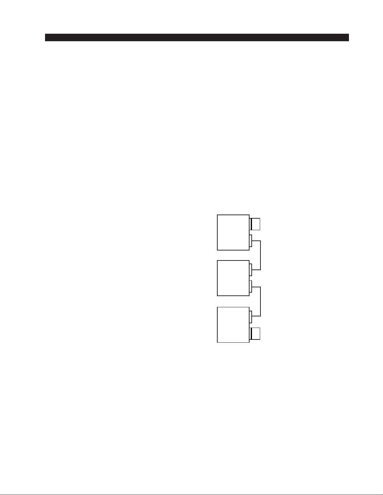
HARDWARE
Stacking Card (CEX-2001)
Overview
The Stacking card is used to connect up to 4 co-located racks into a larger
virtual chassis. The stacking approach is most useful when configuring
medium to large centrally located systems which employ a large number of
analog or digital audio I/O cards. Stacked racks allow full physical access to
all 32 TDM busses by expanding the number of available slots. Remember,
a single chassis has 22 slots which can accommodate a maximum of 20 I/O
cards, whereas a four rack stacked system for example has 88 slots. Only one
chassis (the master chassis) may have an active CPU card.
Configuring the Virtual Chassis
Each stacked chassis must have a single
CEX-2001 chassis expansion card installed in
Slot 1. Each CEX-2001 card is chained together
using the provided high density multipin cables,
similar to that used in SCSI interfaces (pinouts are
NOT identical to SCSI). A cable from Rack1 connects to Rack 2, Rack 2 to Rack 3, etc. The supplied
termination plugs must be fitted to the unused
connectors at both ends of the chain.
MASTER
STACK
RACK IDØ
CAGE 1
RACK ID1
TERMINATOR
CABLE
TDM Assignment
CABLE
When configuring stacked systems, attention
must be given to the number of TDM busses allocated to the master chassis and each expansion rack.
The number of TDM busses in a rack determines the
CAGE n
RACK IDn
TERMINATOR
number of input cards allowed in a rack. Each input
card uses one TDM bus.
The 4 position dipswitch SW3 allows the user to allocate TDM busses in
groups of 8, with each switch position allocating 8 TDM busses. The first
position of SW3 on the CEX-2001 in the master chassis must always be ON,
and conversely the first position of SW3 on the remaining CEX-2001 cards
installed in the expansion racks must always be OFF. How you set the
remaining 3 positions of dipswitch SW3 on each CEX-2001 card determines
how many TDM busses are available to each rack. For example, assume a 2
rack system: switch ON SW3, positions 1 & 2 on the master rack CEX-2001
and SW3, positions 3 & 4 on the second rack’s CEX-2001 card. The master
rack and the expansion rack now each drive 16 TDM’s, giving each rack the
ability to house up to 16 input cards each.
page 2 – 502001 / Jul 01
Page 73
H A R D W A R E
OPEN=SOCKET
CEX-2001 Rack ID
The CEX -2001 Rack ID numbering scheme differs significantly from the
methods used on OAN-2001 and CPU-2001 circuit boards. Stacked racks
have Rack ID’s of 1 through 4 inclusive. The Rack ID numbers for stacked
frames are a by-product of the TDM assignment dipswitch setting described
in the previous section. Each position, 1-4, of the four position dipswitch SW3
also corresponds to Rack ID’s 1-4. The Master rack is always Rack ID 1. The
Rack ID of a stacked expansion rack is always equal to the first position of
SW3 that was turned ON to assign TDM’s on the rack’s CEX-2001 circuit
board . Using the previous two rack TDM Assignment example, the master
Rack ID is 1 and the second Rack ID is 3.
CEX-2001 Configuration Rules
• Dipswitch SW3 serves a dual function, TDM assign plus Rack ID.
• Rack ID in the XP GUI is equal to the 1st SW3 position thrown on a CEX
card.
• The Master rack CEX card always has SW3-1 ON, all others have SW3-1
OFF.
• Each rack must drive at least 8 TDM’s, but not more than 24 TDM’s.
Internal Programming Options
All internal programming choices are made via PCB mounted dipswitches.
Dipswitch functions are shown in the table below.
CEX-2001 PCB
NAME REF.DES.
DRIVERS / RACK-ID
CRYSTAL SELECT
RESET J2
SW3
0000
J1
DEFAULT
SHORT L/R=L/R CRYSTAL
Switch Settings
DIPSW1
This four position dipswitch, SW1, is not used.
SW2 - Reset
Momentary pushbutton resets the stacking card.
DIPSW3 - TDM ASSIGN/RACK ID
SW3 settings are unique for each CEX-2001 card installed. SW3 assigns
TDM busses to its rack and supplies the chassis’ Rack ID to the system
software and XPoint GUI. Please refer to the “Configuring the Virtual
Chassis” section earlier in this chapter for details.
2001 / Jun 02
2001 / Jul 01
page 2 – 51
Page 74

HARDWARE
Jumper Settings
J1 - Crystal Select
Stacking cards are designed to have two clock options - surface
mounted crystals, or a socketed crystal. Surface mount crystals can be
used without crystal in socket - just short the pins closest to the desired
crystal to enable it. Or insert the desired crystal into the socket and
enable it by shorting the enable line to the crystal.
If Y1 and Y2 are populated with surface mount clock oscillators,
and Y3 is not installed (default), then 3 pin jumper posts J1 must be
used to select the correct frequency. A jumper shunt between the center
pin and pin closest to Y1 selects Y1 (48 kHz) and likewise a shunt to
pin closest to Y2 selects Y2 (44.1 kHz).
The clock oscillator on the Stacking card must match the system’s
master clock frequency. If the system audio sample rate is 48 kHz, then
the clock reference must be 24.576 MHz and likewise for 44.1 kHz, a
22.5792 MHz clock is necessary. If only Y3, a DIP socketed clock is
populated and not Y1 or Y2, then the appropriate matching clock
frequency must be installed in Y3.
NOTE: When changing the audio sample rate of the Bridge
2001 Digital Audio Network
Router, changes must be made
in the following places: DO-2001
Digital Output Card, CPU-2001
Host CPU, OAN-2001 Audio
Network Card, CEX-2001 Stacking Card, and QAT-2001 Quad
Audio Network Card. See the
appropriate manual sections for
details.
J2 - Reset
Momentary shorting of this jumper will reset the card and program
the FPGA.
2001 / Jul 01
2001 / Mar 05
page 2 – 52
Page 75
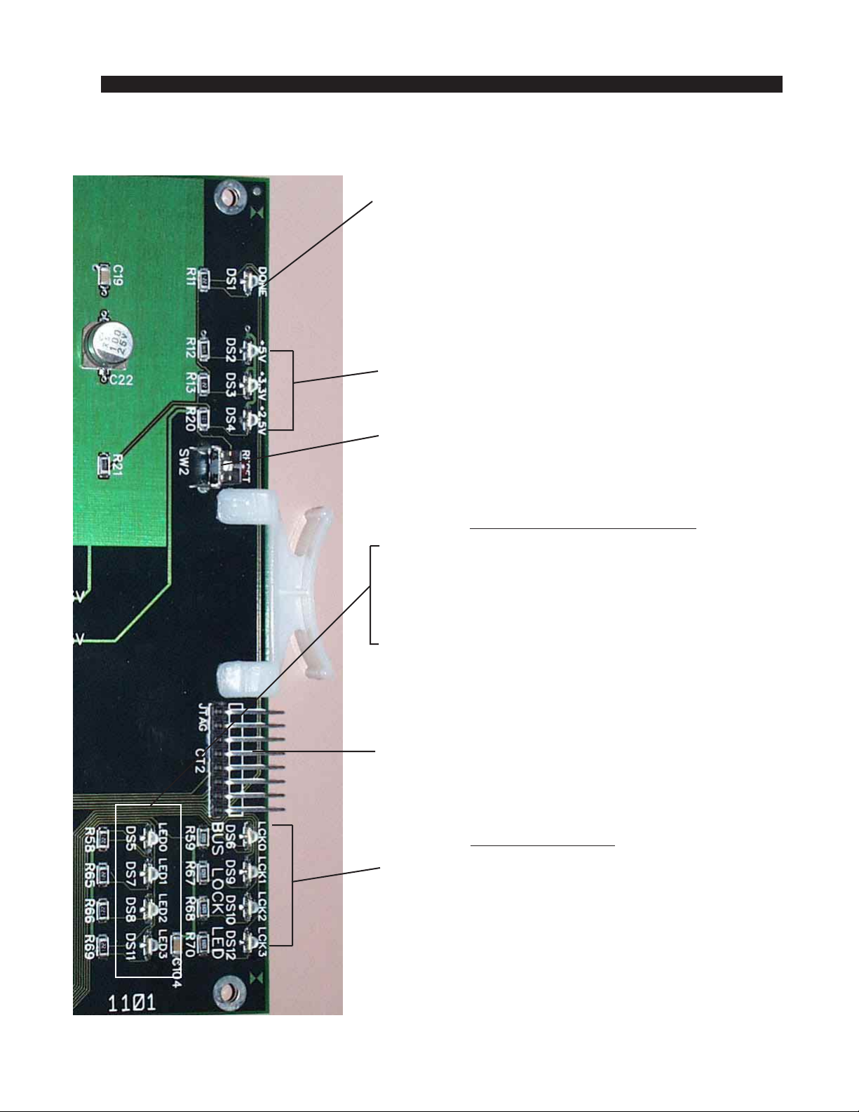
HARDWARE
Stacking Card Status LED’ s
DONE LED (DS1) - Normally OFF;
ON when programming the FPGA ,
Flashes when system clock is missing.
POWER SUPPLY STATUS (DS2-DS4) -
ON indicates power supply is OK.
RESET SWITCH (SW2) - momentary pushbutton.
Resets the OAN card.
AUXILIARY STATUS LED’s
ACTIVITY LED (DS5) - flashes on messages.
BUS 0 LOCK STATUS (DS7) - ON when Bus 0 not locked.
(DS8) - not used, always OFF.
CFG STATUS (DS11) - ON when card is not
configurated.
JTAG HEADER - FPGA programming - factory use only.
BUS LOCK LED’s
LED’s (DS6, DS9, DS10, DS12) ON indicates
unallocated TDM busses- all four LED’s should be OFF
when operational.
page 2 – 532001 / Jul 01
Page 76
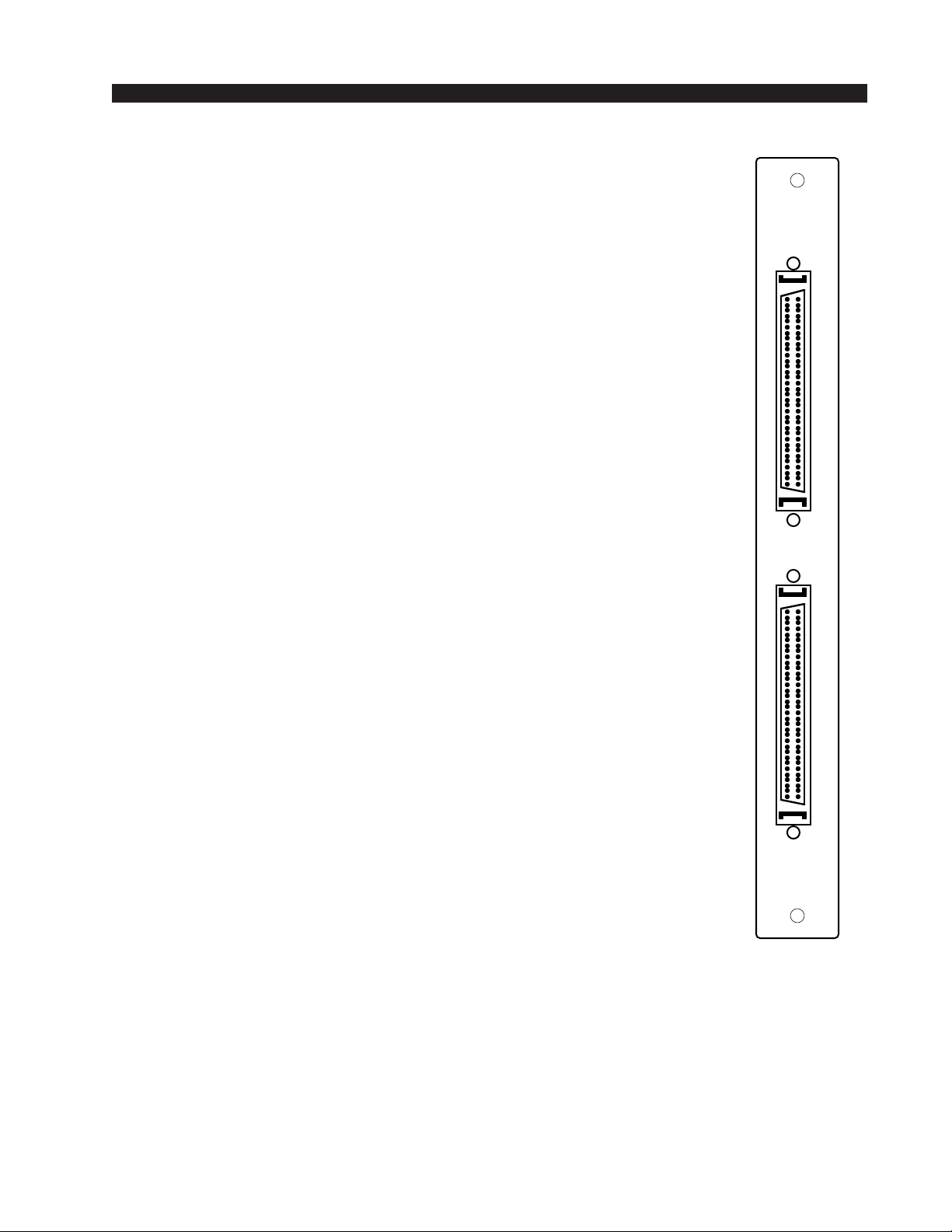
HARDWARE
Hook-Ups
All user wiring to and from Stacking Card takes place at the rear I/O
connectors module (CEI-2001). There are two specially wired high density
SCSI type connectors for looping the Stacking cards together.
1
2
page 2 – 542001 / Jul 01
Page 77
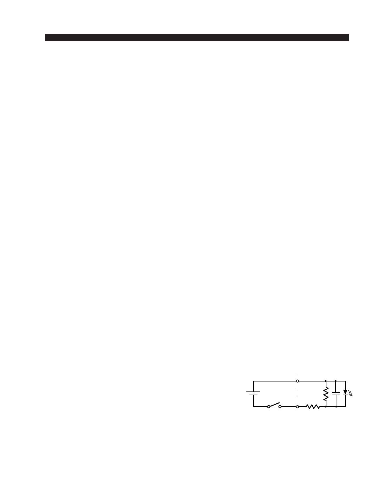
HARDWARE
Logic Input/Output Card
(LIO-2001)
Overview
The LIO-2001 is a programmable hardware GPI with a feature set
designed for broadcast studio control applications. Twelve independent,
opto-isolated solid state relay inputs and outputs may be programmed
through the XPoint GUI software to function as routable logic or trigger
ports.
Routable logic allows the user to make logic signal crosspoints in the
same way audio crosspoints are made. For instance, a closure on logic input
port 1 can be cross connected to logic output port 1. Later, the same closure
on input port 1 can be routed to logic output port 2, 3 or 4 etc. as required.
The output ports may be programmed to follow the input port state or to
invert it. Defining this behavior is useful when configuring the hardware for
normally closed applications. Input and output ports may be configured as
logic I/O only or may be “attached” to an audio signal. Routable logic
signals may be included as part of a Salvo.
Trigger ports allow the user to program a logic input to fire a predefined
Salvo or to make a temporary audio connection. Salvos make or break
multiple audio and/or logic crosspoints, while temporary audio connections are useful for IFB or EAS applications. When an input port is defined
as a trigger port, the corresponding output port is automatically allocated
for tally back. Tally back outputs provide a momentary closure whenever
the corresponding input is activated. Note that trigger ports serve one,
predefined function and are not routable.
See Configuring Logic I/O section in the Software Setup guide.
Input Ports
Each of the twelve LH1522AB solid state relay
input ports are configured as a floating photodiode,
(i.e. + input is the opto’s anode, - input is the opto’s
cathode). A 475 ohm current limiting resistor in
series with each negative input supports an external
supply voltage range of +5Vdc to +15Vdc. For
external supply voltages between +15Vdc and
+24Vdc, install a current limiting resistor of 220
ohms in series with each + input connection. Maximum forward photodiode current is 50mA.
When interfacing to a logic input port, we recommend the positive side
be connected to a fixed, positive dc voltage and the negative side switched
to ground to activate the logic input.
2001 / Jul 01
2001 / Jul 02
EXT
+5V - +15V
SIMPLE INPUT EXAMPLE
ROUTER
LIO IN
page 2 – 55
Page 78
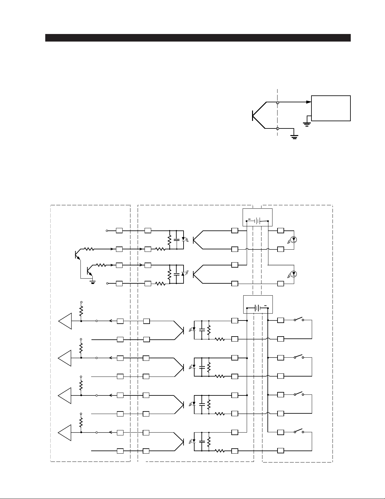
Output Ports
HARDWARE
Each of the twelve LH1522AB solid state relay outputs
may be configured in software to function as normally
open or normally closed circuits when cross connected to
an input. Routable output ports can be programmed to
ROUTER
LIO OUT
default to the ON, OFF or CURRENT states when disconnected from an input port.
All outputs feature linear ac/dc operation, current limiting and a low on resistance, typically 10 ohms.
Normal Operating Load Limits: 120mA, ±100V
Safety Note: The LIO-2001 is NOT designed to safely switch AC mains
power.
Typical Input/Output Circuit
ROUTER ANP-600
LIO IN
LIO OUT
25
12
24
11
ON TALLY
OFF TALLY
MMD #1
DIGITAL
DIGITAL
+5V
11
15
2
5
12
25
24
11+5V
SIMPLE OUTPUT EXAMPLE
EXT DEVICE
PLAY IN
GND
EXT V+
+
5
ON TALLY
LED
15
OFF TALLY
LED
2
2001 / Jul 01
2001 / Jul 02
+5V
+5V
+5V
+5V
EXT ON
DGND
EXT OFF
DGND
COUGH
DGND
TB
DGND
EXT V+
+
LIO OUT LIO IN
16
4
3
17
1
23
14
10
12
25
11
24
10
23
9
22
12
25
11
24
10
23
9
22
16
ON
23
3
OFF
10
1
COUGH
4
14
TB
17
page 2 – 56
Page 79

HARDWARE
Software Programming
For details on programming the LIO-2001, please refer to the “Logic I/O
Control” chapter in the XPoint Software Setup Guide later in this manual.
Internal Programming Options
There are no user programming options on the LIO-2001 card.
Jumper / Dipswitch Settings
J1 - Not installed.
J2 - Default IN - FPGA reset enable.
J3 - Not installed.
SW1-4 - Not used.
2001 / Jul 01
page 2 – 57
Page 80
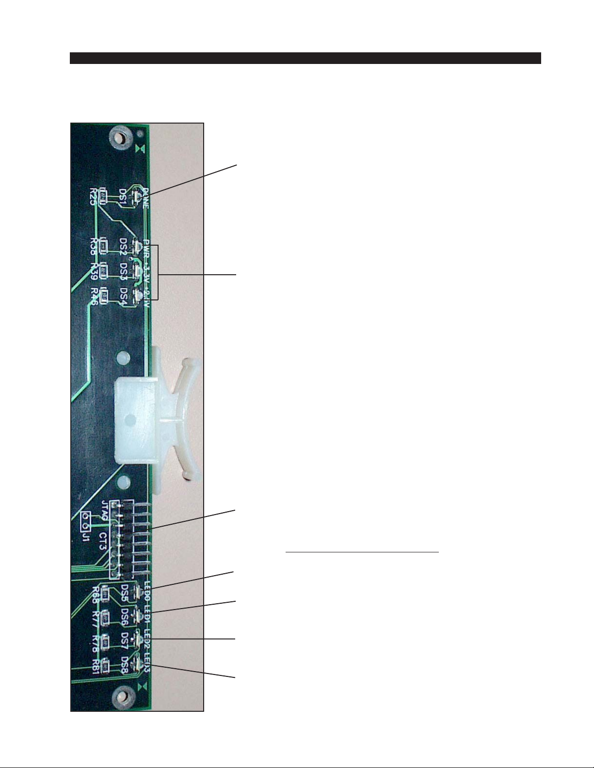
HARDWARE
Logic Input/Output Card Status LED’ s
DONE LED (DS1) - Normally OFF;
ON when programming the FPGA,
Flashes when system clock is missing.
POWER SUPPLY STATUS (DS2-DS4) - ON indicates
power supply is OK.
2001 / Jul 01
2001 / Jul 02
JTAG HEADER - FPGA programming - factory use only.
AUXILIARY STATUS LED’s
SYS ACTIVITY LED (DS5) - Flashes on config messages.
INPUT PORT ACTIVITY (DS6) - Flashes on logic input
message.
OUTPUT PORT ACTIVITY (DS7) - Flashes on logic output
message.
CFG STATUS (DS8) - ON when card is not configured.
page 2 – 58
Page 81

HARDWARE
Hook-Ups
All user wiring to the LIO-2001 card takes place at the 2DB rear
I/O connector module. The 2DB module has two female DB-25
connectors for logic input and output connections.
Upper DB-25—Logic Input Connections
These include 12 input sources. Pinout drawing on page 2-61 shows
all wiring connections at a glance.
Pin 12 – Logic 1 In +
Pin 25 – Logic 1 In -
Pin 11 – Logic 2 In +
Pin 24 – Logic 2 In -
Pin 10 – Logic 3 In +
Pin 23 – Logic 3 In -
Pin 9 – Logic 4 In +
Pin 22 – Logic 4 In -
Pin 8 – Logic 5 In +
Pin 21 – Logic 5 In -
Pin 7 – Logic 6 In +
Pin 20 – Logic 6 In -
Pin 6 – Logic 7 In +
Pin 19 – Logic 7 In -
Pin 5 – Logic 8 In +
Pin 18 – Logic 8 In -
Pin 4 – Logic 9 In +
Pin 17 – Logic 9 In -
Pin 3 – Logic 10 In +
Pin 16 – Logic 10 In -
Pin 2 – Logic 11 In +
Pin 15 – Logic 11 In -
Pin 1 – Logic 12 In +
Pin 14 – Logic 12 In -
Lower DB-25—Logic Output Connections
These include 12 output sources. Pinout drawing on page 2-61
shows all wiring connections at a glance.
Pin 12 – Logic 1 Out +
Pin 25 – Logic 1 Out -
Pin 11 – Logic 2 Out +
Pin 24 – Logic 2 Out -
Pin 10 – Logic 3 Out +
Pin 23 – Logic 3 Out -
Pin 9 – Logic 4 Out +
Pin 22 – Logic 4 Out -
2001 / Jul 01
2001 / Jul 02
page 2 – 59
Page 82

Pin 8 – Logic 5 Out +
Pin 21 – Logic 5 Out -
Pin 7 – Logic 6 Out +
Pin 20 – Logic 6 Out -
Pin 6 – Logic 7 Out +
Pin 19 – Logic 7 Out -
Pin 5 – Logic 8 Out +
Pin 18 – Logic 8 Out -
Pin 4 – Logic 9 Out +
Pin 17 – Logic 9 Out -
Pin 3 – Logic 10 Out +
Pin 16 – Logic 10 Out -
Pin 2 – Logic 11 Out +
Pin 15 – Logic 11 Out -
Pin 1 – Logic 12 Out +
Pin 14 – Logic 12 Out -
HARDWARE
2001 / Jul 01
2001 / Jul 02
page 2 – 60
Page 83
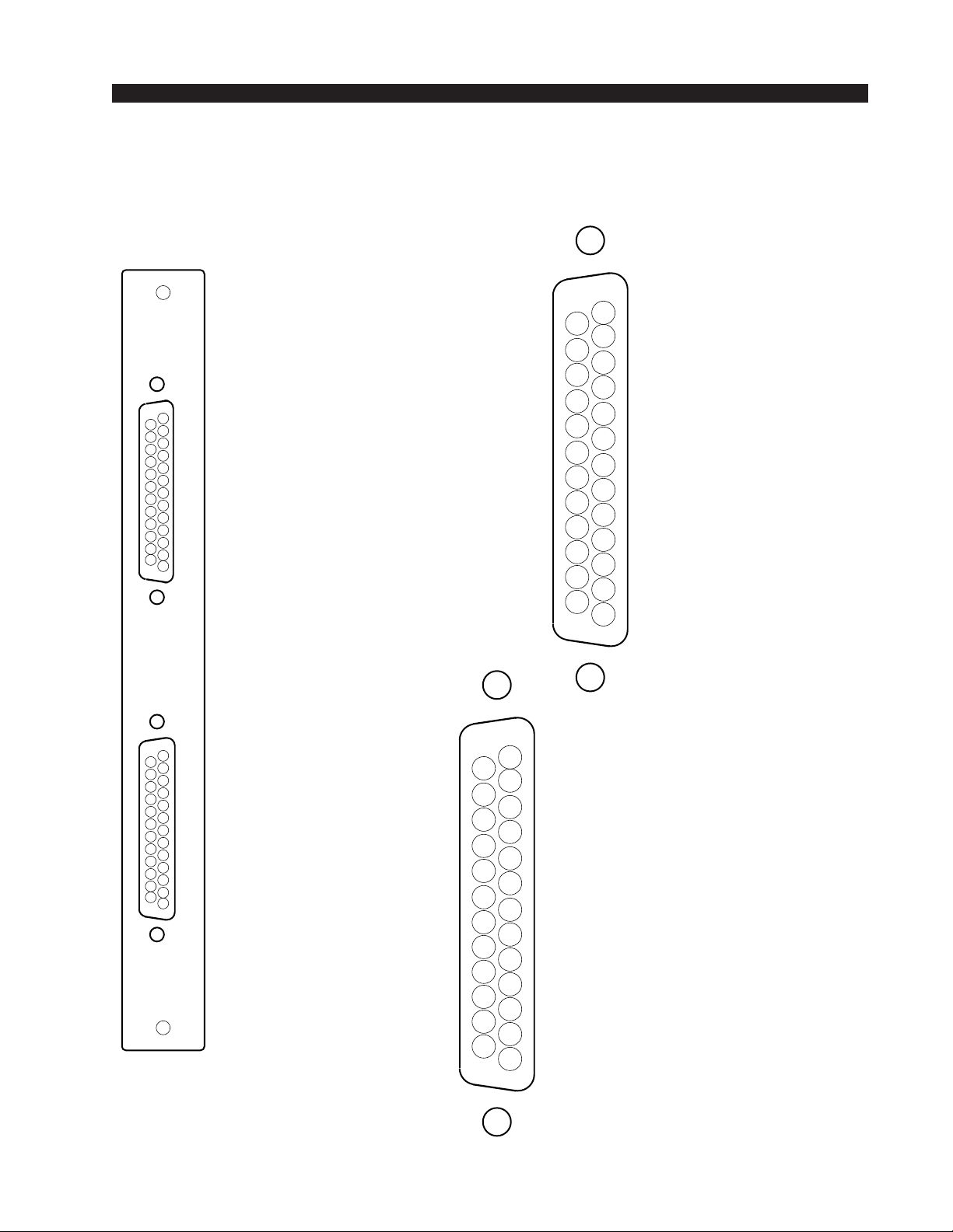
HARDWARE
2DB Panel
Logic I/O Connections
A
B
LOGIC IN PORTS
(Upper "A" DB-25)
LOGIC 1 OUT LOGIC 2 OUT LOGIC 3 OUT LOGIC 4 OUT LOGIC 5 OUT LOGIC 6 OUT LOGIC 7 OUT -
LOGIC 8 OUT -
LOGIC 9 OUT LOGIC 10 OUT LOGIC 11 OUT LOGIC 12 OUT -
LOGIC 1 IN LOGIC 2 IN LOGIC 3 IN -
LOGIC 4 IN LOGIC 5 IN LOGIC 6 IN LOGIC 7 IN LOGIC 8 IN LOGIC 9 IN -
LOGIC 10 IN LOGIC 11 IN -
LOGIC 12 IN -
13
25
12
24
11
23
10
22
9
21
8
20
7
19
6
18
5
17
4
16
3
15
2
14
1
13
25
12
24
11
23
10
22
9
21
8
20
7
19
6
18
5
17
4
16
3
15
2
14
1
AUDIO GROUND
LOGIC 1 OUT +
LOGIC 2 OUT +
LOGIC 3 OUT +
LOGIC 4 OUT +
LOGIC 5 OUT +
LOGIC 6 OUT +
LOGIC 7 OUT +
LOGIC 8 OUT +
LOGIC 9 OUT +
LOGIC 10 OUT +
LOGIC 11 OUT +
LOGIC 12 OUT +
AUDIO GROUND
LOGIC 1 IN +
LOGIC 2 IN +
LOGIC 3 IN +
LOGIC 4 IN +
LOGIC 5 IN +
LOGIC 6 IN +
LOGIC 7 IN +
LOGIC 8 IN +
LOGIC 9 IN +
LOGIC 10 IN +
LOGIC 11 IN +
LOGIC 12 IN +
LOGIC OUT PORTS
(Lower "B" DB-25)
2001 / Jul 01
2001 / Jul 02
page 2 – 61
Page 84
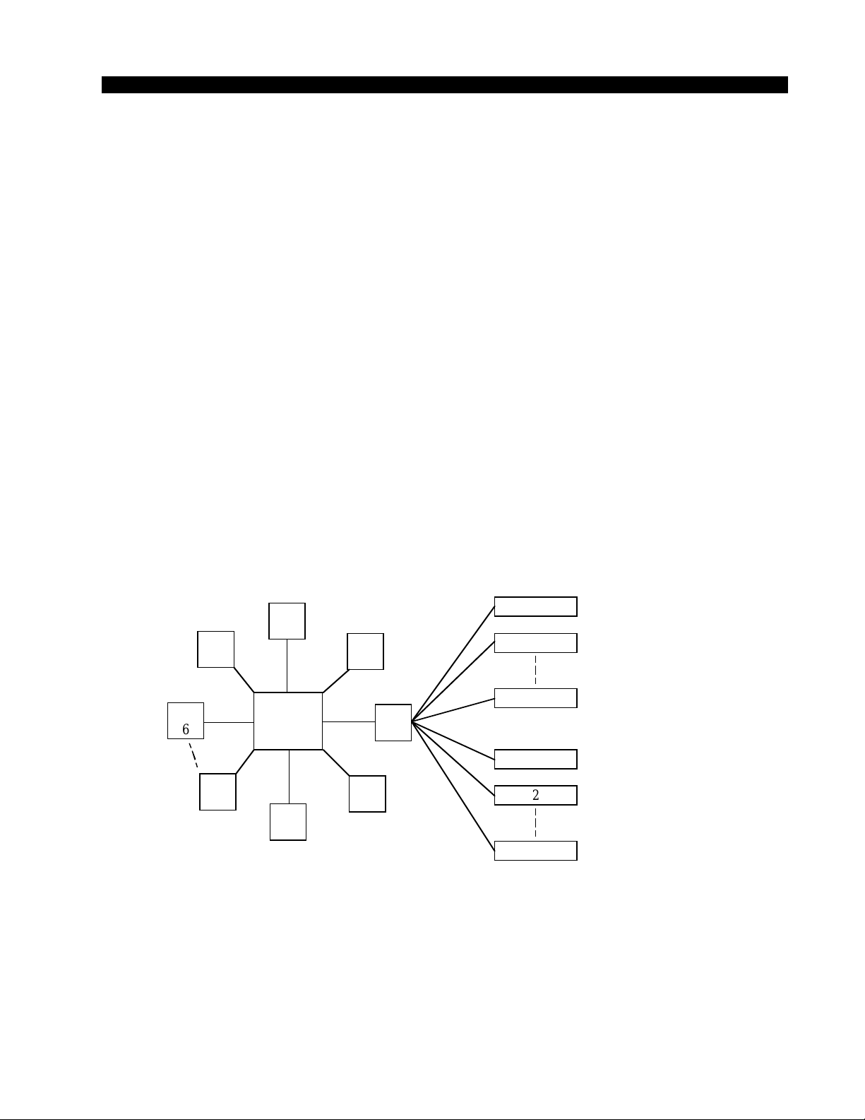
HARDWARE
Quad Audio Network Card
(QA T-2001)
Overview
The Quad Audio Network card provides a robust and deterministic link
between multiple audio racks or control surfaces via fiber optic or CAT-5
cable. The 4 ports, A,B,C & D, may be independently configured in hardware
for either audio or control surface connections. Ports configured for Audio
Transport are called “AT” links, while ports configured for control surface use
are called “MT” or Mixer Transport links. Wheatstone’s XPoint software is
used to map the QAT ports to specific control surfaces and audio racks.
In a Multi-Tiered system, QAT cards are used as the “spoke” connections
between the Hub switch and up to 14 Remote Tiers. Control surfaces and
Satellite cages may then be connected to the master racks of the remote Tiers
through additional QAT cards.
SURFACES
1
2
6
1
2
6
TIER
6
TIER
5
TIER
13
TIER
4
TIER1
MASTER
HUB
TIER
14
TIER
3
TIER
15
TIER
2
SATELLITE RACKS
Audio transport links must be installed in pairs (i.e. a QAT Network port
in the master chassis communicates to a companion QAT port or OAN card
in the remote chassis). Each QAT port transceives up to 64 mono channels (32
stereo signals). Each AT port must be configured as Local or Remote, and
Primary or Secondary. All Local/Primary ports transmit the sample rate clock
while all Remote/Primary ports receive the sample rate clock and drive it onto
its local backplane.
2001 / Jul 01
2001 / Sep 03
page 2 – 62
Page 85
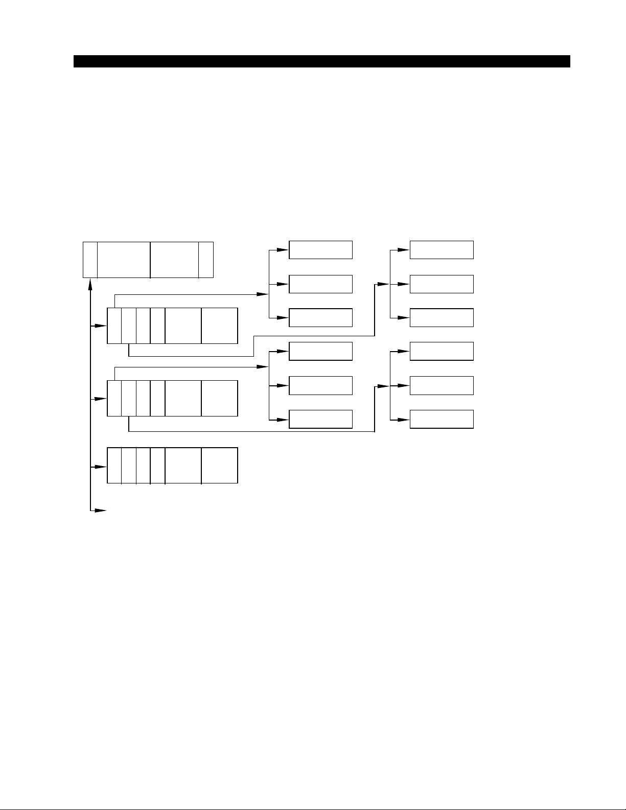
HARDWARE
In systems incorporating control surfaces and DSP, each control surface
link is made to a QAT port co-located with its corresponding DSP cards.
These “MT” ports carry all fader, switch, logic, LCD meter, source and
destination information to and from the control surface and the companion
DSP cards located in the Remote Tier racks. Local/Remote and Primary/
Secondary settings do NOT apply to ports configured as Mixer Transport
links.
HUBS SURFACES
MASTER RACK HUB
Q
A
AUDIO
T
Q
Q
A
B
C
D
D
A
A
S
T
T
P
PRODUCTION HUB
Q
Q
D
A
A
S
T
T
P
Q
Q
D
A
A
S
T
T
P
SPARE
C
LOGIC
AIR HUB
D
SPAUDIO LOGIC
D
SPAUDIO LOGIC
NEWS HUB
D
AUDIO
S
P
P
U
LOGIC
B
SURF 1
C
SURF 2
D
SURF 3
B
PROD SURF 1
C
PROD SURF 2
D
PROD SURF 3
A
B
C
A
B
C
TYPICAL QAT SIGNAL FLOW
SATELLITE
RACKS
AIR RACK 1
AIR RACK 2
AIR RACK 3
PROD RACK 1
PROD RACK 2
PROD RACK 3
While the QAT provides a tremendous amount of flexibility and routing
power, please note the following design aspects:
• There is no audio data on an MT link.
• Control surfaces may not be daisy chained together off a single MT port.
• Audio cards in a remote chassis do not communicate directly with each other.
• In a single Tier configuration, a remote chassis cannot be daisy chained to
another remote chassis.
2001 / Jul 01
2001 / Sep 03
page 2 – 63
Page 86
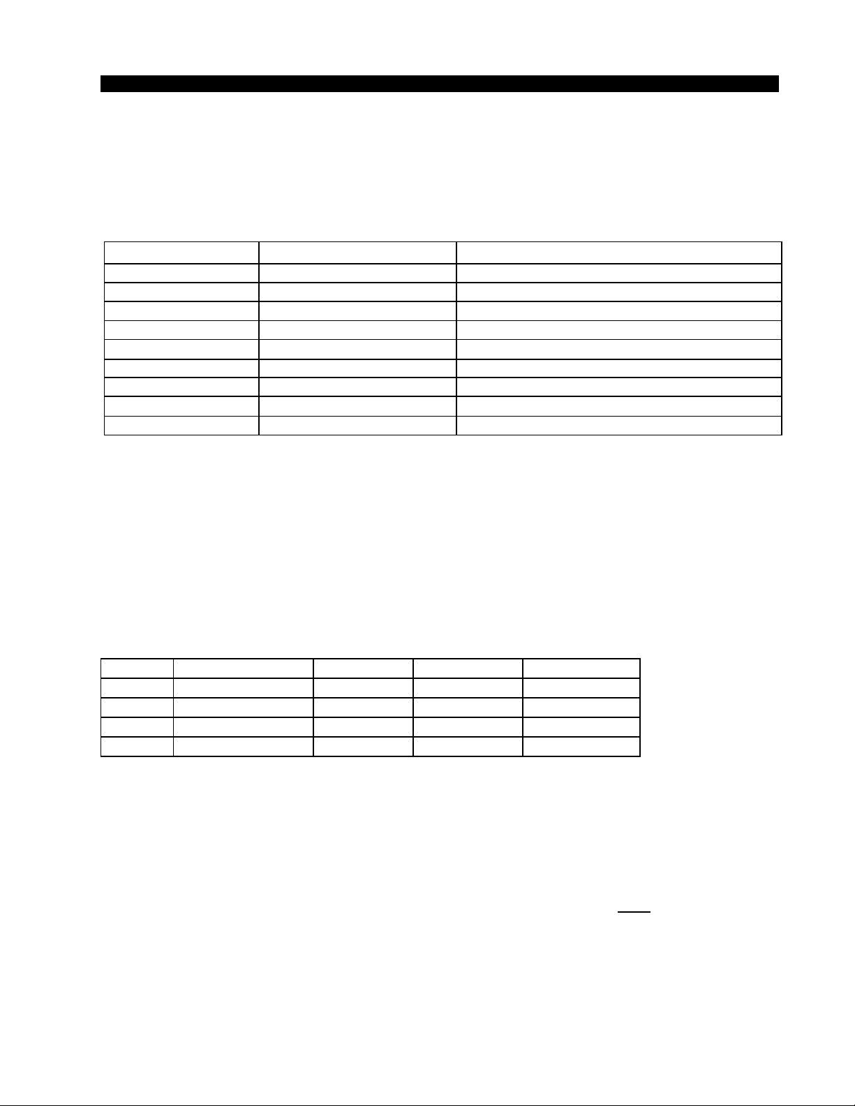
HARDWARE
Internal Programming Options
All internal programming are made via PCB mounted dipswitches.
Dipswitch settings are shown in the table below:
QAT-2001 PCB
NAME REF.DES.
RACK-ID
LOCAL/REMOTE
PRIMARY/SECONDARY
MEDIA
AUDIO/CONSOLE
SAMPLE RATE J3
485_A_TERM
485_B_TERM
RESET SHORT=RESET
SW6
SW9 (Ports A B C D)
SW8 (Ports A B C D)
SW7 (Ports A B C D)
SW10 (Ports A B C D)
SW4, SW5
SW1, SW2
J1, J2 = not installed
see Breakout Table - DIPSW6 Rack ID
LOCAL=ON
PRIMARY=ON SECONDARY=OFF
CAT5=ON FIBER=OFF
AUDIO=ON CONSOLE=OFF
48kHz=OPEN
see Breakout Table - DIPSW 1, 2, 4 &5 485 Termination
see Breakout Table - DIPSW1, 2, 4 &5 485 Termination
REMOTE=OFF
44.1kHz=SHORT
Switch Settings
DIPSW1, SW2, SW4 & SW5 - 485 Termination
These four 4-position dipswitches configure the 485 port termination as
follows:
SW1-SW4
POSITION BIASED TERM PASSIVE TERM UNTERMINATED
1 - TX10Ω
2 - TX+
3 - TX4 - 120Ω
Choices are Unterminated, Normal Termination, or BIAS Termination on
the transmit and receive lines. SW4 and SW5 are for Port A, and SW1 and
SW2 are for Port B. SW2 and SW5 are for the RS-485 transmitter’s
termination; SW1 and SW4 are for receiver terminations.
An RS-485 bus may only be BIAS TERMINATED at one end. All
applicable Bridge 2001 QAT and CPU cards are set for BIAS TERMINATION by default. All peripheral devices are set for NO TERMINATION by
default. Set the TERMINATION to ON for the last controller or console only,
in a RS-485 chain.
FUNCTION
ON=10Ω BYPASS
ON=750Ω PULLUP
ON=750Ω PULLDOWN
ON=120Ω PARALLEL
OFF*
ON*
ON*
ON*
ON
OFF
OFF
ON
OFF
OFF
OFF
OFF
* Default
2001 / Jul 01
2001 / Sep 03
page 2 – 64
Page 87

HARDWARE
DIPSW7 - Fiber/CAT5 Ports A-B-C-D
Selects whether the audio network or control surface connection will be
made through optical fiber or copper CAT-5 cable.
DIPSW8 - Primary/Secondary Ports A-B-C-D
Some system configurations may have multiple QAT cards in each rack.
The Primary setting is used to distinguish which QAT port will act as the
Clock/Sync master in the Remote chassis. All other AT ports in the Remote
rack must be set to Secondary.
• The system’s master chassis must have only one LOCAL-PRIMARY
QAT port connected to each companion Remote chassis.
• Each Remote chassis must have only one REMOTE-PRIMARY QAT
port.
DIPSW9 - Local/Remote (Clock Source) Ports A-B-C-D
The Local/Remote setting is required to configure QAT ports such that a
Local card will operate from the backplane clock/sync references. A Remote
Primary port would likewise infer that clock/sync are to be extracted from
Fiber/CAT5 and driven onto backplane. Local/Remote does not apply when
the port type is set to CONSOLE.
• The system’s master chassis must have only one LOCAL-PRIMARY
QAT port connected to each companion Remote chassis.
• Each Remote chassis must have only one REMOTE-PRIMARY QAT
port.
DIPSW10 - Audio/Console (Port Type) Ports A-B-C-D
Selects the type of equipment connected to each of the 4 QAT ports.
• Select AUDIO to connect a remote or master cage to the port.
• Select CONSOLE to connect a control surface to the port.
SW3 - Reset
Momentary switch resets the LAN chip, press and hold also resets the
FPGA.
2001 / Jul 01
2001 / Sep 03
page 2 – 65
Page 88
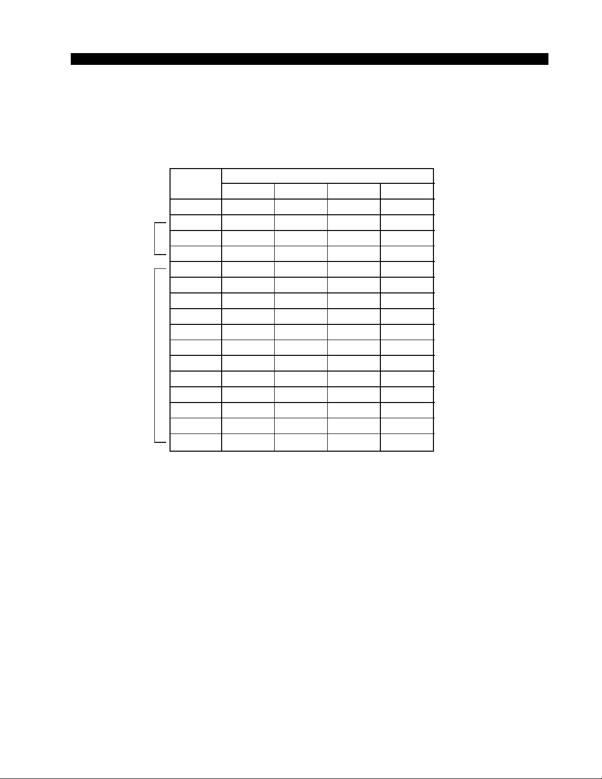
HARDWARE
DIPSW6 - Rack ID
If the QAT card is a Remote-Primary Audio Network Card, this QAT card
must supply the Rack ID to its backplane from the 4 bit onboard switch. Remote
Rack ID’s must be 5 or higher.
SW6 RACK ID
SW7
OFF OFF ON
MASTER CPU
RESERVED
FOR
STACKING
USED FOR
AUDIO
NETWORK
CHASSIS
RACK ID
1
2
3
4
5
6
7
8
9
10
11
12
13
14
15
16
RACK ID8
RACK ID4 RACK ID2 RACK ID1
OFF OFF OFF OFF
OFF OFF OFF ON
OFF OFF ON OFF
OFF OFF ON ON
OFF ON OFF OFF
OFF ON OFF ON
OFF ON ON OFF
OFF ON ON ON
ON OFF OFF OFF
ON
ON OFF ON OFF
ON OFF ON ON
ON ON OFF OFF
ON ON OFF ON
ON ON ON OFF
ON ON ON ON
• Each remote chassis must have only one REMOTE-PRIMARY QAT card.
Note: Rack ID numbers are coded in binary: Rack ID 1 equals binary Ø‚ Rack
ID 2 equals binary 1, etc.
Rack ID’s are set at the factory. Incorrect setting of these switches can cause
system malfunction.
Jumper Settings
J1 - Factory Use Only - Reset
Momentary shorting does a complete reset.
J2 - Factory Use Only- Watchdog Disable
Normally installed; Remove to disable watchdog reset.
J3 - Sample Rate Select - 48kHz / 44.1kHz*
Selects the system’s sample rate frequency; 48kHz or 44.1 kHz.
An open jumper selects 48 kHz, and a shunt selects 44.1 kHz.
2001 / Jul 01
2001 / Sep 032001 / Mar 05
*NOTE: When changing the audio sample rate of the Bridge
2001 Digital Audio Network
Router, changes must be made
in the following places: DO-2001
Digital Output Card, CPU-2001
Host CPU, OAN-2001 Audio
Network Card, CEX-2001 Stacking Card, and QAT-2001 Quad
Audio Network Card. See the
appropriate manual sections for
details.
page 2 – 66
Page 89
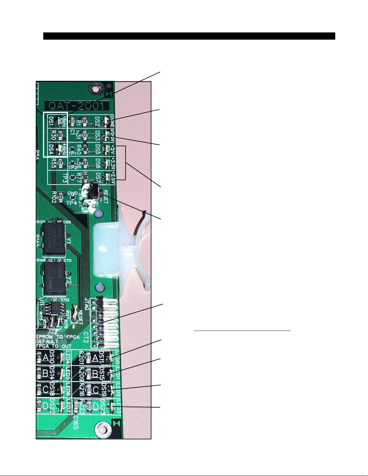
HARDWARE
QA T Card Status LED’ s
SAMPLE RATE STATUS DS1 - ON indicates that the rate is 48 kHz
DS4 - ON indicates that the rate is 44.1 kHz
DONE LED (DS2) - Normally OFF;
ON when programming the FPGA,
Flashes when system clock is missing.
FIBER INTERFACE (DS3) - lights when Fiber rear
panel card is powered.
POWER SUPPLY STATUS (DS5-DS7) -
ON indicates power supply is OK.
RESET SWITCH (SW3) - momentary pushbutton.
Resets the QAT card.
JTAG HEADER - FPGA programming - factory use only.
AUXILIARY STATUS LED’s
FLOW CONTROL (DS11) - Normally flashes; Stuck ON
indicates problem.
SURF MSG (DS15) - Normally Flashes; Stuck ON indicates
surf coefficent comm problem.
SURF CTL MSG (DS19)- Normally Flashes; Stuck ON
indicates surf control message problem.
2001 / Jul 01
2001 / Sep 03
SURF COMM ERROR (DS22) - Normally Flashes;
Stuck indicates surface comm problem.
page 2 – 67
Page 90
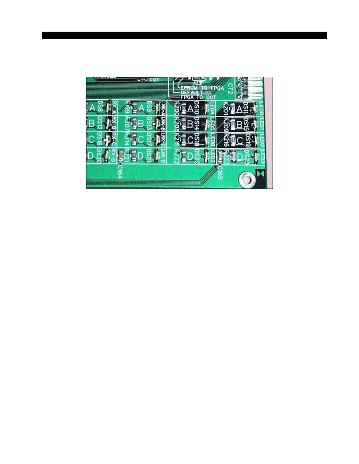
HARDWARE
LINK STATUS LED’s
RX STATUS (DS8,12,16,20) - ON indicates that the data
A, B, C or D receive link is OK.
LINK STATUS (DS9,13,17,21) - ON indicates that a hard ware A, B, C or D link is established.
ACTIVITY LED (DS10) - Flashes on port messages.
CLOCK MASTER (DS14) - ON indicates that this QAT card supplies the
backplane clock.
COMM ERROR (DS18) - Normally OFF; ON for errors.
CFG/BUFFER ERROR (DS23) - Normally OFF; Flashes when the card is
not configured. Once configured, DS23
indicates buffer errors.
2001 / Jul 01
2001 / Sep 03
page 2 – 68
Page 91
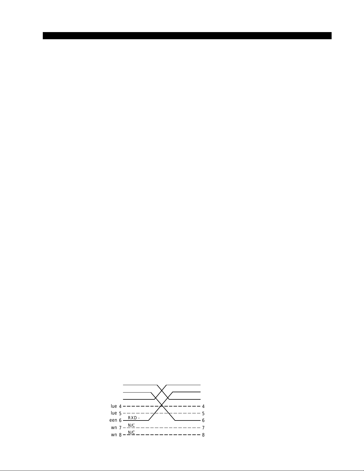
HARDWARE
/CN/C
/C
/C
/CN/C
/C
/C
Hook-Ups
All user wiring to and from QAT-2001 Card takes place at the two rear I/O
connector modules: The QCT-2001 is used for CAT5 connections made via four
RJ-45 connectors. The QOT-2001 is used for multi-mode optical fiber connections made via four SC type optical connectors (optical fiber interface described
on the page 2-48). There are also female DB-9 serial port connectors (two on the
QCT-2001 panel and one on the QOT-2001 panel) for use as RS-485/RS-232
communication links to Wheatstone consoles and XY controllers. Pinout drawings on pages 2-70 and 2-71 shows all wiring connections at a glance.
Upper “A” DB-9—Serial Interface Port 1 Connector
Pin 3 – RX1 HI (RS-485)
Pin 8 – RX1 LO (RS-485)
Pin 1 – TX1 HI (RS-485)
Pin 6 – TX1 LO (RS-485)
Pin 2 – TX1 (RS-232)
Pin 7 – RX1 (RS-232)
Pin 5 - GND
*Lower “B” DB-9—Serial Interface Port 2 Connector
(*not available on the optional fiber optic rear panel)
Pin 3 – RX2 HI (RS-485)
Pin 8 – RX2 LO (RS-485)
Pin 1 – TX2 HI (RS-485)
Pin 6 – TX2 LO (RS-485)
Pin 2 – TX2 (RS-232)
Pin 7 – RX2 (RS-232)
Pin 5 - GND
“A”, “B”, “C”, “D” RJ-45—CAT5 Audio Network Connectors
Pin 1 – TXD +
Pin 2 – TXD Pin 3 – RXD +
Pin 4 – N/C
Pin 5 – N/C
Pin 6 – RXD -
Pin 7 – N/C
Pin 8 – N/C
CAT5 Crossover Cable for QAT to QAT Connections
RJ-45
Plug
White/Orange
Orange
White/Green
Blue
White/Blue
Green
White/Brown
Brown
PIN
1
2
3
4
5
6
7
8
TXD +
TXD -
RXD +
N
N
RXD -
N
RXD +
RXD TXD +
N
N
TXD N
PIN
White/Green
1
Green
2
White/Orange
3
Blue
4
White/Blue
5
Orange
6
White/Brown
7
Brown
8
RJ-45
Plug
2001 / Jul 01
2001 / Sep 03
page 2 – 69
Page 92
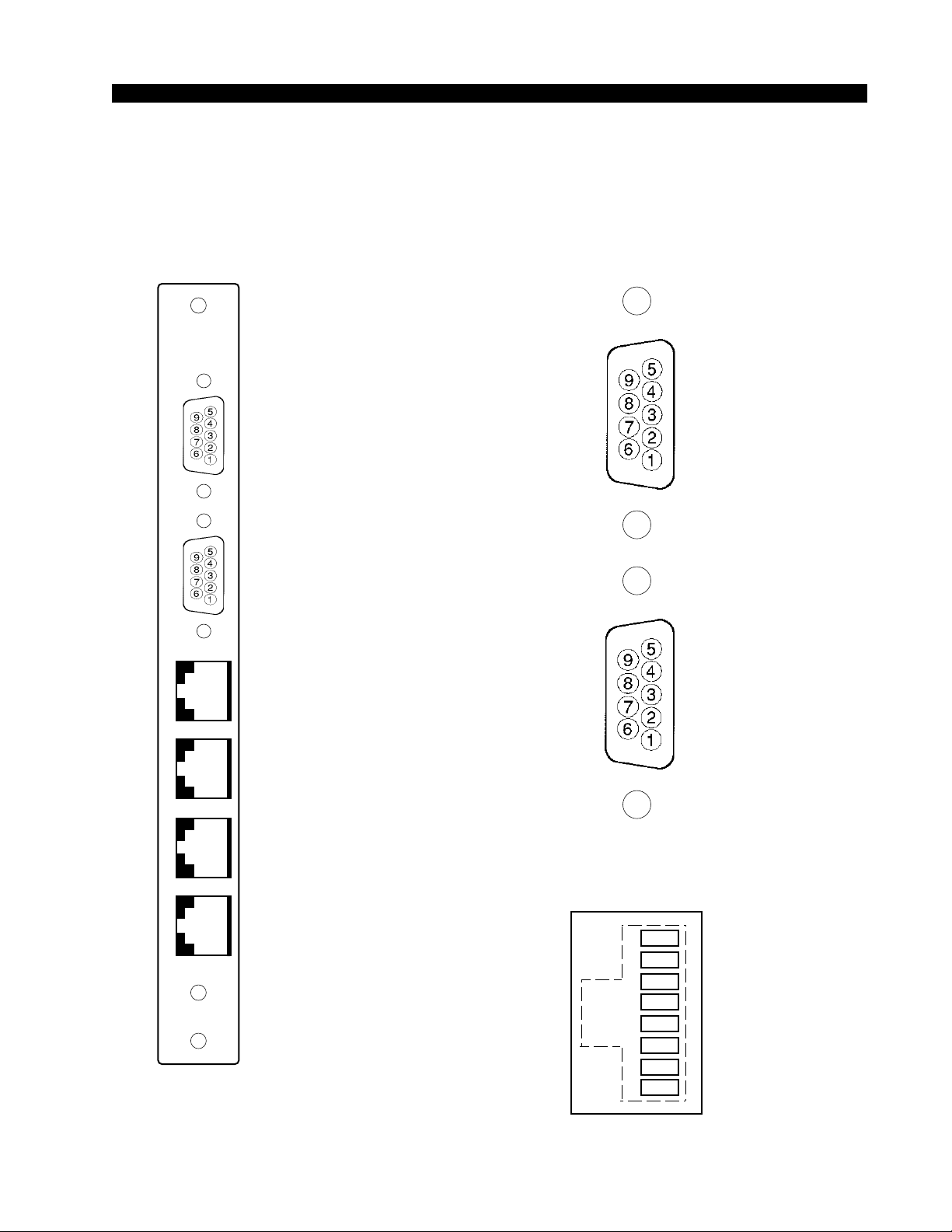
SERIAL
AAB
C
D
B
+
-
+
-
I/O Connections
I/O PORTS
(Upper "A"
DB-9)
HARDWARE
QCT Panel
RX1 LO (RS-485)
RX1 (RS-232)
TX1 LO (RS-485)
N/C
GND
N/C
RX1 HI (RS-485)
TX1 (RS-232)
TX1 HI (RS-485)
OK
CAT 5
I/O PORTS
(Lower "B"
DB-9)
"A", "B", "C" & "D")
RX2 LO (RS-485)
RX2 (RS-232)
TX2 LO (RS-485)
Audio Network
Connector
(RJ-45
N/C
GND
N/C
RX2 HI (RS-485)
TX2 (RS-232)
TX2 HI (RS-485)
1
2
3
4
5
6
7
8
TXD
RXD
N/C
N/C
N/C
N/C
TXD
RXD
2001 / Jul 01
2001 / Sep 03
page 2 – 70
Page 93
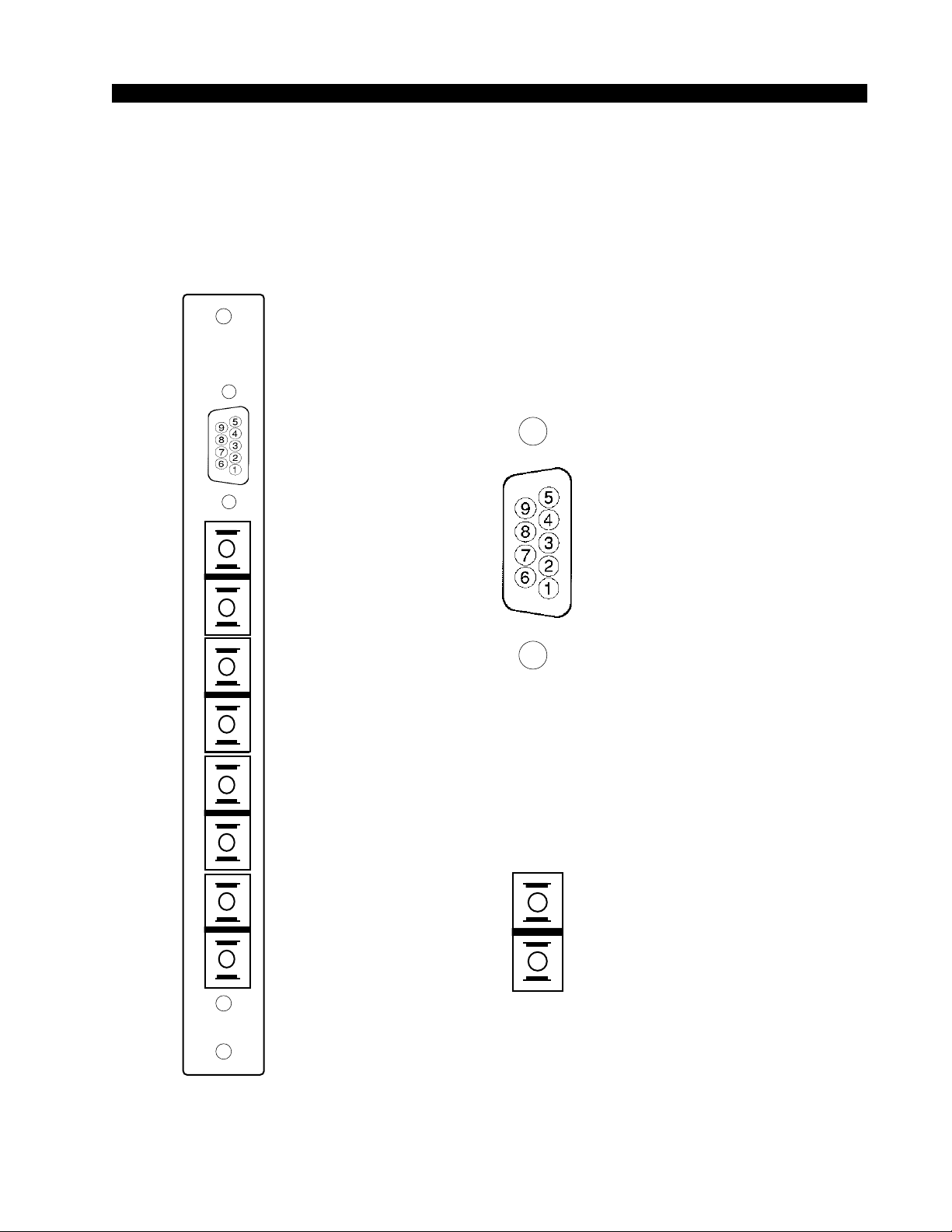
HARDWARE
ABCDA
QOT Panel
I/O Connections
SERIAL
N/C
RX1 LO (RS-485)
RX1 (RS-232)
TX1 LO (RS-485)
I/O PORTS
(Upper "A"
DB-9)
GND
N/C
RX1 HI (RS-485)
TX1 (RS-232)
TX1 HI (RS-485)
Audio Network
(SC Connector
"A", "B", "C" & "D")
TX
RX
OK
OPTO
2001 / Jul 01
2001 / Sep 03
page 2 – 71
Page 94

HARDWARE
Digital Signal Processor Card
(DSP-2001)
Overview
The DSP-2001 card is the digital signal processing card used by the
Bridge System to mix and condition input signals. DSP cards in a given
system are physically identical. Their fuctionality is determined by input
and mix software which is loaded into each DSP card’s memory on surface
powerup. Wheatstone’s XPoint software is used to map each DSP card to
specific control surfaces and audio racks.
DSP cards are installed in pairs for radio style control surfaces, with one
DSP card acting as an input signal conditioner and the other as a mix
engine. Larger production and television surfaces with 5.1 surround
capabilities have a dedicated Master Mix engine along with multiple Mix
and Input DSP cards. The exact number of DSP cards requisite in large
systems is a function of the number of input channels and mix bus
requirements.
Each input fader has a dedicated DSP channel which is responsible for
gain, mode, phase, EQ, dynamics and metering. Likewise, each output mix
has a dedicated DSP channel responsible for summing, gain, mode,
metering and EQ/Dynamics on 5.1 Master mix outputs. DSP cards receive
instructions from control surfaces in real time over a Mixer Transport or
“MT” link. The mix engine DSP’s combine all of the console audio signals
as directed by a console’s faders, knobs and switches to produce the
various Program, Aux Send, Mix Minus and Monitor output mixes.
Racks may be fitted with one or more backup or “self healing” DSP
cards. If a hardware problem disables a primary DSP card, the affected
surface will load the appropriate code into one of the backup DSP cards and
continue to function. Replacing the faulty primary DSP card will return the
surface to normal operation, freeing the backup card for future use.
Warning messages present on the surface and in the XPoint GUI indicate
that a card has failed and requires attention.
Internal Programming Options
All internal programming are made via PCB mounted switches.
2001 / Jul 01
2001 / Sep 03
page 2 – 72
Page 95

HARDWARE
Switch Settings
SW1 - DSP Reset Switch
Momentary press and hold resets the DSP and reloads software from surface.
DIPSW2 -
Not used
Jumper Settings
J1 - Factory Use Only - Watchdog Reset
Momentary shorting does a complete reset.
J2 - Factory Use Only - Watchdog Reset
Momentary shorting does a complete reset.
J3 - Factory Use Only- Watchdog Disable
Normally installed; Remove to disable watchdog reset.
2001 / Jul 01
2001 / Sep 03
page 2 – 73
Page 96
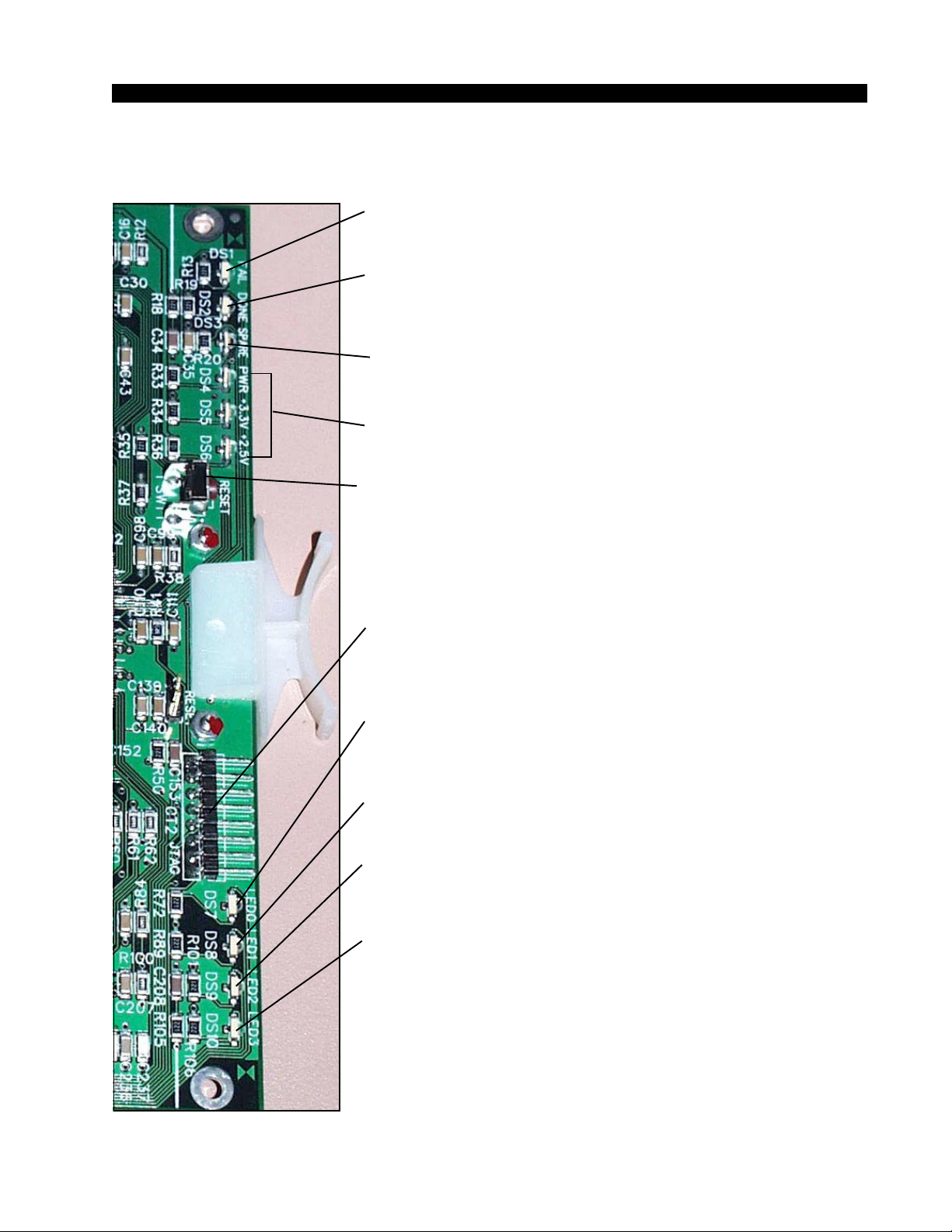
HARDWARE
DSP Card Status LED’ s
FAIL (DS1) - Normally OFF;
Lights to indicate card failure.
DONE LED (DS2) - Normally OFF;
ON when programming the FPGA,
Flashes when system clock is missing.
ERROR (DS3) - Normally OFF;
Lights to indicate clock error.
POWER SUPPLY STATUS (DS4-DS6) - ON indicates
power supply is OK.
RESET SWITCH (SW1) - momentary pushbutton. Hold for
2 seconds for complete reset of
CPU and FPGA.
JTAG HEADER - FPGA programming - factory use only.
BACKPLANE RESPONSE (DS7) - lights as the card
responds to backplane
messages.
MESSAGE (DS8) - ON indicates that messages are being
received from control surface.
SYNCH (DS9) - ON indicates clock SYNCH signal.
CONFIGURATION (DS10) - ON indicates card needs
configuration from HOST.
NOTE: Normal operation is (3) power status LEDs always ON,
all other LEDs OFF, except DS7 lights once every
≈ 40 seconds and DS8 flickers in response to control
changes on the control surface.
2001 / Jul 01
2001 / Jul 03
2001 / Sep 03
page 2 – 74
Page 97

HARDWARE
Microphone Card (MIC-2001)
Overview
The Microphone input/output cards accept 8 mono microphone input
audio sources and provides 8 mono direct output channels. A Signal Defini-
tions form in the supplied XPoint software allows the user to set attributes for
the input and output channels hardware including signal name, type, circuit
#, etc.
The balanced, mic level input signals are amplified by a remote controlled
dual stage preamplifier. Each preamplified microphone signal is fed to a
balanced, line level direct output. The preamplified microphone signal is also
converted to the digital domain by 24bit A-D converters operating at the
system’s master sample rate. Embedded logic routes each channel of audio
data into an available time slot of the card’s TDM bus. One TDM bus is
allocated for each card.
Analog Input Interface
The MIC-2001 uses an electronically balanced, monolithic preamplifier
capable of a wide range of input signals. While all microphone inputs employ
high frequency filtering components, be sure to install a high quality
microphone cable to help eliminate unwanted EMI and RFI artifacts.
Preamp specifications:
Nominal Mic Level = - 50dBm (2mV RMS), 150 ohms
Max input level = -10dBu
Headroom = 20dB
Gain Max = 84dB
Gain Range = +20 to +80dB
Phantom Power = 32V
Direct Output Level = 10dB steps
Internal Programming Options
There are no internal programming options on the MIC-2001 card.
2001 / Jul 01
2001 / Oct 03
page 2 – 75
Page 98
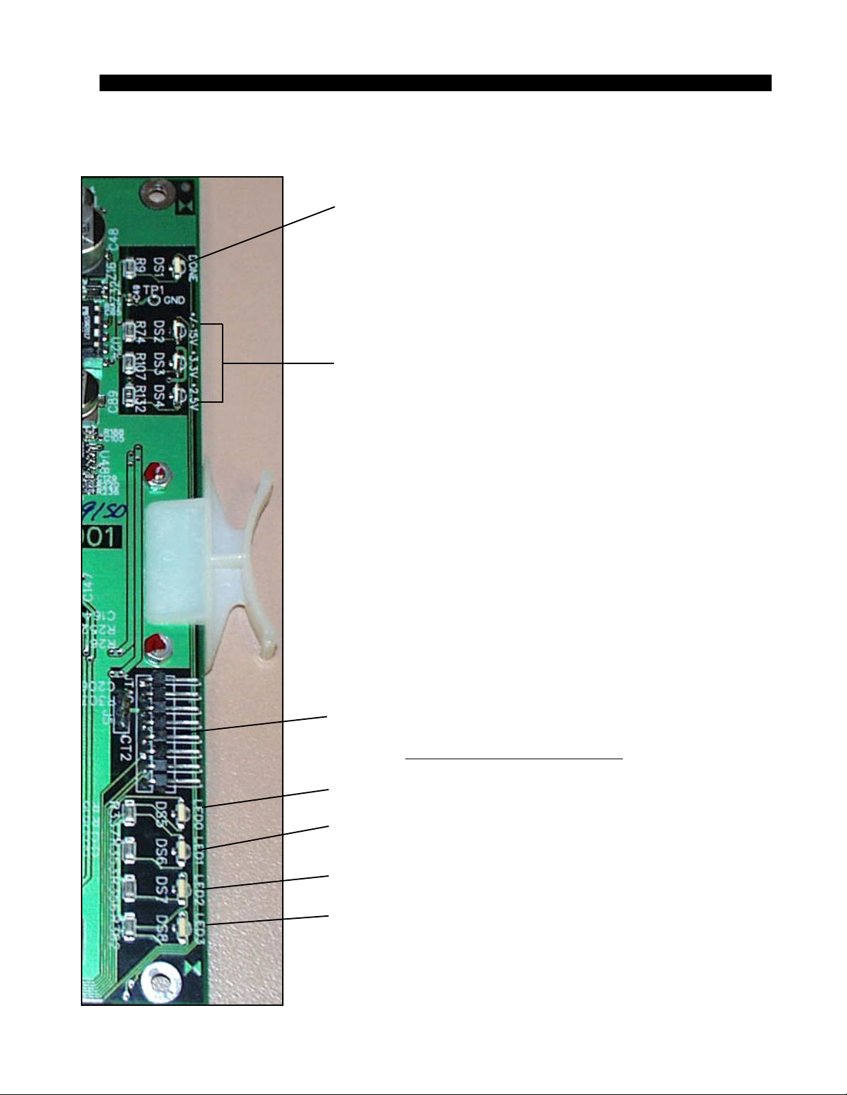
HARDWARE
Microphone Card Status LED’s
DONE LED (DS1) - Normally OFF;
ON when programming the FPGA,
Flashes when system clock is missing.
POWER SUPPLY STATUS (DS2-DS4) - ON indicates
power supply is OK.
2001 / Jul 01
2001 / Oct 03
JTAG HEADER - FPGA programming - factory use only.
AUXILIARY STATUS LED’s
ACTIVITY LED (DS5) - flashes on messages.
DS6 - NOT USED
MUTE STATUS (DS7) - ON when the input channels
are muted.
CFG STATUS (DS8) - ON when card is not
configured.
page 2 – 76
Page 99
HARDWARE
Hook-Ups
All user wiring to the MIC-2001 card takes place at the rear I/O connectors
modules: 2DB or 8RJ-45. The 2DB module has two female DB-25 connectors
for audio input/output connections. The 8RJ-45 module contains eight RJ-45
connectors for use in balanced, unshielded twisted pair (UTP) wiring systems.
Upper DB-25—Analog Audio Input Connections
These include eight mic input sources. Pinout drawing on page 2-79
shows all wiring connections at a glance.
Pin 24 – HI
Pin 12 – LO Mic 1 In
Pin 25 – SH
Pin 10 – HI
Pin 23 – LO Mic 2 In
Pin 11 – SH
Pin 21 – HI
Pin 9 – LO Mic 3 In
Pin 22 - SH
Pin 7 – HI
Pin 20 – LO Mic 4 In
Pin 8 – SH
Pin 18 – HI
Pin 6 – LO Mic 5 In
Pin 19 – SH
Pin 4 – HI
Pin 17 – LO Mic 6 In
Pin 5 – SH
Pin 15 – HI
Pin 3 – LO Mic 7 In
Pin 16 – SH
Pin 1 – HI
Pin 14 – LO Mic 8 In
Pin 2 – SH
Lower DB-25—Analog Audio Output Connections
These include eight direct output sources. Pinout drawing on page 2-79
shows all wiring connections at a glance.
Pin 24 – HI
Pin 12 – LO Direct 1 Out
Pin 25 – SH
Pin 10 – HI
Pin 23 – LO Direct 2 Out
Pin 11 – SH
Pin 21 – HI
Pin 9 – LO Direct 3 Out
Pin 22 - SH
2001 / Jul 01
2001 / Oct 03
page 2 – 77
Page 100
HARDWARE
Pin 7 – HI
Pin 20 – LO Direct 4 Out
Pin 8 – SH
Pin 18 – HI
Pin 6 – LO Direct 5 Out
Pin 19 – SH
Pin 4 – HI
Pin 17 – LO Direct 6 Out
Pin 5 – SH
Pin 15 – HI
Pin 3 – LO Direct 7 Out
Pin 16 – SH
Pin 1 – HI
Pin 14 – LO Direct 8 Out
Pin 2 – SH
8 RJ-45—Analog Audio Connections
For analog input connections use 1-4 connectors, and for direct output use 58 connectors. Pinout drawing on page 2-80 shows all wiring connections at a
glance.
2001 / Jul 01
2001 / Oct 03
RJ-45#1 Pin 3 – HI
RJ-45#1 Pin 6 – LO
RJ-45#1 Pin 1 – HI
RJ-45#1 Pin 2 – LO
RJ-45#2 Pin 3 – HI
RJ-45#2 Pin 6 – LO
RJ-45#2 Pin 1 – HI
RJ-45#2 Pin 2 – LO
RJ-45#3 Pin 3 – HI
RJ-45#3 Pin 6 – LO
RJ-45#3 Pin 1 – HI
RJ-45#3 Pin 2 – LO
RJ-45#4 Pin 3 – HI
RJ-45#4 Pin 6 – LO
RJ-45#4 Pin 1 – HI
RJ-45#4 Pin 2 – LO
RJ-45#5 Pin 3 – HI
RJ-45#5 Pin 6 – LO
RJ-45#5 Pin 1 – HI
RJ-45#5 Pin 2 – LO
RJ-45#6 Pin 3 – HI
RJ-45#6 Pin 6 – LO
RJ-45#6 Pin 1 – HI
RJ-45#6 Pin 2 – LO
RJ-45#7 Pin 3 – HI
RJ-45#7 Pin 6 – LO
RJ-45#7 Pin 1 – HI
RJ-45#7 Pin 2 – LO
RJ-45#8 Pin 3 – HI
RJ-45#8 Pin 6 – LO
RJ-45#8 Pin 1 – HI
RJ-45#8 Pin 2 – LO
Mic 1 In
Mic 2 In
Mic 3 In
Mic 4 In
Mic 5 In
Mic 6 In
Mic 7 In
Mic 8 In
Direct 1 Out
Direct 2 Out
Direct 3 Out
Direct 4 Out
Direct 5 Out
Direct 6 Out
Direct 7 Out
Direct 8 Out
page 2 – 78
 Loading...