


Read this manual before using product. Failure
X-SERIES 13" AUGERS
X130-74, X130-84, X130-94
ASSEMBLY AND OPERATION MANUAL
to follow instructions and safety precautions can
result in serious injury, death, or property
damage. Keep manual for future reference.
Part Number: 30787 R1
Revised: 22/7/2013

This product has been designed and constructed according to general engineering
standardsa. Other local regulations may apply and must be followed by the operator.
We strongly recommend that all personnel associated with this equipment be trained
in the correct operational and safety procedures required for this product. Periodic
reviews of this manual with all employees should be standard practice. For your
convenience, we include this sign-off sheet so you can record your periodic reviews.
Date Employee Signature Employer Signature
a. Standards include organizations such as the American Society of Agricultural and Biological Engineers,
American National Standards Institute, Canadian Standards Association, International Organization for
Standardization, and/or others.

WHEATHEART - X13 SERIES AUGERS
X1374, X1384, X1394
TABLE OF CONTENTS
1. Introduction.......................................................................................................................... 7
1.1. Overview .................................................................................................................. 8
1.1.1. Auger Power Source .................................................................................. 8
1.1.2. Grain Transfer Boot.................................................................................... 9
1.1.3. Grain Hopper............................................................................................ 10
1.1.4. Auger Tube Hydraulic Lift......................................................................... 11
2. Safety .................................................................................................................................. 13
2.1. General Safety Information .................................................................................... 13
2.2. Assembly Safety..................................................................................................... 14
2.3. ............................................................................................................................... 15
2.4. Operating Safety .................................................................................................... 15
2.5. Hydraulic Safety..................................................................................................... 15
2.6. PTO Driveline Safety.............................................................................................. 16
2.7. Tire Safety.............................................................................................................. 16
2.8. Transport Safety..................................................................................................... 17
2.9. Storage Safety........................................................................................................ 17
2.10. Maintenance Safety.............................................................................................. 17
2.11. Safety Decals....................................................................................................... 18
2.11.1. Decal Installation.................................................................................... 18
2.11.2. Safety Decal Locations........................................................................... 18
3. Assembly ............................................................................................................................ 23
3.1. General Assembly.................................................................................................. 23
3.2. Identify Auger Tube Sections................................................................................. 25
3.3. Assemble the Main Auger Tube............................................................................. 28
3.4. Install the Boot on the Auger tube.......................................................................... 29
3.5. Install Boot Bearing, Lower Sprocket, and Drive Chain ......................................... 31
3.6. Install the Boot Tow Bar......................................................................................... 32
3.7. Install the Discharge Spout .................................................................................... 33
3.8. Set the Thrust Adjuster........................................................................................... 33
3.9. Apply Logo and Model Decals................................................................................ 34
3.10. Auger Tube Truss Assembly................................................................................ 35
3.10.1. X130-74 Auger Tube Truss Assembly.................................................... 35
3.10.2. X130-84/X130-94 Auger Tube Truss Assembly..................................... 40
3.11. Assemble the Auger Frame................................................................................. 49
3.12. Installing the Hydraulic Cylinders......................................................................... 56
3.13. Assemble Wheel Hubs and Install Tires............................................................... 57
3.14. Attaching the Auger Tube to the Frame............................................................... 58
3.15. Connecting Hydraulic Hose to Cylinders.............................................................. 61
3.16. Install Low Profile Intake Hopper.......................................................................... 65
3.17. Installing the Hopper Lift Arm and Winch............................................................. 69
3.18. Install the Hitch Jack ........................................................................................... 72
3.19. Connecting the PTO Driveline.............................................................................. 72
3.20. Auger-to-Tractor Hookup...................................................................................... 74
30787 R1 3

WHEATHEART - X13 SERIES AUGERS
X1374, X1384, X1394
TABLE OF CONTENTS
4. Transport............................................................................................................................. 77
4.1. Transport Procedure............................................................................................... 77
5. Placement ........................................................................................................................... 81
5.1. Placement Procedure............................................................................................. 81
5.2. Positioning Tractor for Right-angle Drive Operation............................................... 85
6. Operation ............................................................................................................................ 87
6.1. Pre-operation Checklist......................................................................................... 87
6.2. Operator Controls................................................................................................... 88
6.2.1. PTO Drive Operation................................................................................ 89
6.2.2. Hydraulics Operation................................................................................ 89
6.3. Operating Procedures ............................................................................................ 90
6.3.1. Initial Start-Up........................................................................................... 90
6.3.2. Normal Start.............................................................................................. 91
6.3.3. Normal Shutdown..................................................................................... 92
6.3.4. Emergency Stop / Full-Tube Restart ........................................................ 93
6.3.5. Reverser Operation .................................................................................. 94
6.3.6. Lowering & Completion............................................................................. 97
7. Maintenance........................................................................................................................ 99
7.1. Maintenance Intervals ............................................................................................ 99
7.2. Fluids and Lubricants ........................................................................................... 100
7.3. Maintenance Procedures...................................................................................... 100
7.3.1. Visual Inspection..................................................................................... 100
7.3.2. Hydraulic Hose and Coupler Inspection ................................................. 101
7.3.3. Machine Greasing................................................................................... 101
7.3.4. Hopper Lift Cable Inspection .................................................................. 103
7.3.5. Winch and Pulley Servicing.................................................................... 103
7.3.6. Swing Tube Coupler Chain Servicing..................................................... 104
7.3.7. Boot and Hopper Chain Drive Servicing................................................. 105
7.3.8. Gearbox Oil Level................................................................................... 106
7.3.9. Machine Cleaning................................................................................... 107
7.3.10. Tire Pressure Check............................................................................. 107
7.3.11. Wheel Bearings Repack....................................................................... 107
7.3.12. Wheel Bolt Tightening........................................................................... 107
7.3.13. Cable Adjustment (X130-74) ................................................................ 108
7.3.14. Cable Adjustment (X130-84, X130-94)................................................. 109
7.3.15. Changing Gearbox Oil.......................................................................... 110
8. Storage.............................................................................................................................. 111
9. Troubleshooting ............................................................................................................... 113
4 30787 R1

WHEATHEART - X13 SERIES AUGERS
X1374, X1384, X1394
10. Appendix......................................................................................................................... 115
10.1. Specifications..................................................................................................... 115
10.2. Bolt Torque Values ............................................................................................ 116
Warranty Registration ........................................................................................................... 119
Limited Warranty................................................................................................................... 121
30787 R1 5

WHEATHEART - X13 SERIES AUGERS
X1374, X1384, X1394
6 30787 R1

WHEATHEART - X13 SERIES AUGERS 1. INTRODUCTION
X1374, X1384, X1394
1. Introduction
Congratulations on the purchase of your new Wheatheart X13 Series Auger. This
equipment will complement your agricultural operation by safely and efficiently
moving grain, pulse crops, fertilizer, and any other granular materials.
Many of the features incorporated into this machine are the result of suggestions
made by customers like you. Your new Wheatheart auger will serve you well if
you understand how it operates, and if you use it and care for it properly. This
manual is intended to help you learn how to operate and maintain your
equipment in a safe, efficient, and trouble-free manner. Please read this manual
before you use your new grain auger .
This manual covers all X13 Series augers built by Wheatheart Manufacturing.
Use the table of contents as a guide when searching for specific information.
Keep this manual in a safe place for future reference and for ordering
replacement parts.
Should any information remain unclear after thoroughly reviewing this manual,
contact your Wheatheart Dealer for clarification before operating your auger.
Knowing the serial number and date of purchase will save time in getting your
questions answered. Please write down this information in the space provided
below.
30787 R1 7
1. INTRODUCTION WHEATHEART - X13 SERIES AUGERS
1.1. OVERVIEW X1374, X1384, X1394
1.1. OVERVIEW
X13 augers are equipped with standard features that include a hydraulically
controlled main auger tube lift, a low-profile grain hopper (left or right side
operation), service access doors, and a PTO driveline for auger power.
Available option kits include:
• Hydraulic Winch
• Hydraulic Power Swing for Hopper
• Electric Power Swing for Hopper
• Right Angle Drive
• 540 RPM PTO Reverser
• 1000 RPM PTO Drive and Reverser
1.1.1. AUGER POWER SOURCE
The power source for the auger is a standard 540 RPM tractor PTO (see Figure
1.1). An optional Right-Angle PTO Drive kit allows the auger to be powered by a
tractor positioned at a 90 degree angle to the auger (Figure 1.2).
An optional 1000 RPM PTO Drive kit provides a speed reducer that allows use
with 1000 RPM PTO tractors, as well as reverser capability that is used to rotate
the auger flightings in the reverse direction (transferring grain in the auger tube
back to the hopper).
An optional 540 RPM Reverser kit provides a similar reverser capability for
540 RPM PTO connections.
Figure 1.1 Standard PTO Driveline
8 30787 R1
WHEATHEART - X13 SERIES AUGERS 1. INTRODUCTION
GRAIN TRANSFER BOOT
SWING ARM SPOUT HEAD
OVERFLOW
PTO DRIVELINE
HITCH
HITCH JACK
SPOUT HEAD
SERVICE HATCH
CLEAN-OUT HATCH
MANUAL WINCH (HOPPER)
BALL
VALVE
PANEL
X1374, X1384, X1394 1.1. OVERVIEW
Figure 1.2 Right Angle PTO Driveline Kit
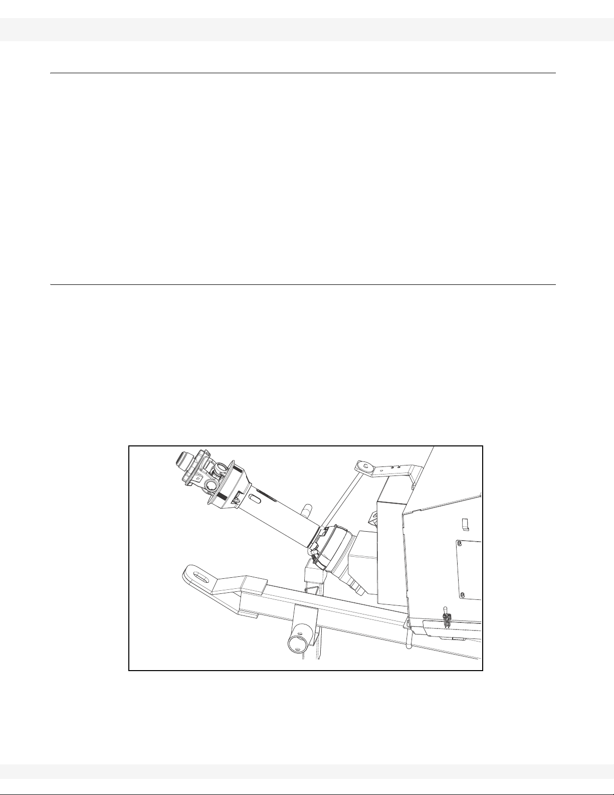
1.1.2. GRAIN TRANSFER BOOT
The grain transfer boot is located at the bottom of the main auger tube, and
contains gearing for power transfer as well as flights for transferring grain.
30787 R1 9
Figure 1.3 Grain Transfer Boot
1. INTRODUCTION WHEATHEART - X13 SERIES AUGERS
1.1. OVERVIEW X1374, X1384, X1394
PTO driveline connection (including connection to the optional 540 RPM PTO
Reverser and 1000 RPM PTO Drive) is provided on the back of the boot, above
the tractor hitch (and hitch jack).
The ball valve used to raise or lower the main auger tube is located on the side of
the boot (see figure below), as is the manual winch used to raise and lower the
grain hopper (see section 6.1. for further information on auger controls).
Several access hatches are provided for maintenance and repair (the swing arm
spout head access hatch is shown below), as well as an overflow panel on the
swing-arm spout head and a clean-out hatch at the bottom of the boot.
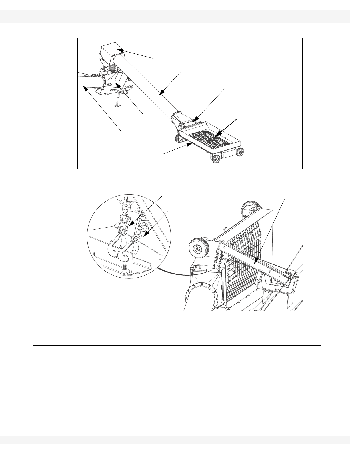
1.1.3. GRAIN HOPPER
The low-profile grain hopper is designed to be rolled into position to receive grain
for transfer through the boot to the auger discharge spout. Ground clearance can
be adjusted by raising or lowering the position of the hopper wheel axles.
The grain hopper must be lifted and secured for transport using the hopper lift
arm, winch (hydraulic or manual operation, according to the installed option), and
transport chain and hook (see Figure 1.5).
The grain hopper provides service to the side of the auger that it is installed on,
but the hopper, lift arm, and winch can be quickly reconfigured to install the
hopper on the other side if required.
Do not approach, open or close the maintenance hatch located on the transition
between the swing are tube and the hopper unless all power to the auger is
locked out.
DANGER
Rotating Auger Hazard
Contact with rotating flighting will result in
amputation or severe laceration.
DO NOT operate with guards removed or
modified.
Keep hands and feet away from rotating
auger.
Tie up long hair and remove jewelry.
DO NOT wear loose-fitting clothing or items
that could become caught.
Shut off and lock out the power source before
unplugging or cleaning.
10 30787 R1
WHEATHEART - X13 SERIES AUGERS 1. INTRODUCTION
INTAKE HOPPER
FLIGHTS AND
SWING ARM
MAINTENANCE HATCH
SPOUT HEAD
MAIN AUGER TUBE
BOOT
FLIGHT GUARDING
WINCH CABLE AND HOOK
SAFETY CHAIN AND HOOK
HOPPER LIFT ARM
X1374, X1384, X1394 1.1. OVERVIEW
Figure 1.4 Grain Hopper
Figure 1.5 Grain Hopper Lifted into Transport Position
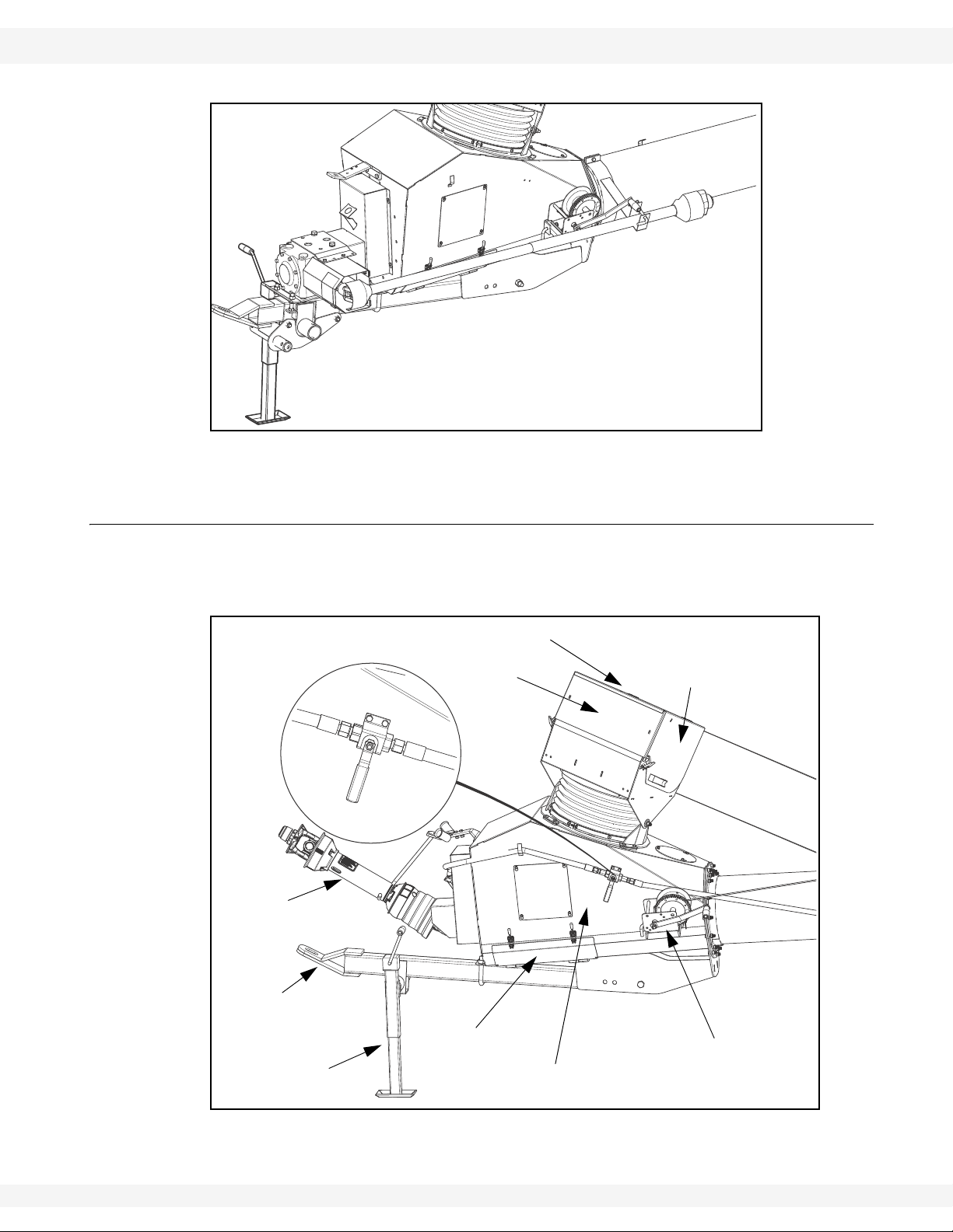
1.1.4. AUGER TUBE HYDRAULIC LIFT
The auger tube is raised and lowered using two single-acting hydraulic cylinders
powered by the hydraulic supply of the connected tractor . The main auger tube is
raised by extending the cylinders, and lowered by allowing the cylinders to
retract.
A hydraulic ball valve mounted on the side of the grain pick-up boot controls flow
of hydraulic fluid to the lift cylinders, and with appropriate use of the hydraulic
controls on the connected tractor, allows the main auger tube to be raised,
lowered, or locked at a specific height during operation (see “Operator Controls”
30787 R1 11
on page 79).

1. INTRODUCTION WHEATHEART - X13 SERIES AUGERS
1.1. OVERVIEW X1374, X1384, X1394
12 30787 R1
WHEATHEART - X13 SERIES AUGERS 2. SAFETY
X1374, X1384, X1394 2.1. GENERAL SAFETY INFORMATION
2. Safety
2.1. GENERAL SAFETY INFORMATION
The Safety Alert symbol identifies important safety messages on the product and
in the manual. When you see this symbol, be alert to the possibility of personal
injury or death. Follow the instructions in the safety messages.
Why is SAFETY important?
• Accidents disable and kill.
• Accidents cost.
• Accidents can be avoided.
SIGNAL WORDS: Note the use of the signal words DANGER, WARNING,
CAUTION, and NOTICE with the safety messages. The appropriate signal word
for each message has been selected using the definitions below as a guideline.
DANGER
Indicates an imminently hazardous situation
that, if not avoided, will result in serious injury
or death.
WARNING
Indicates a hazardous situation that, if not
avoided, could result in serious injury or
death.
CAUTION
Indicates a hazardous situation that, if not
avoided, may result in minor or moderate
injury.
NOTICE
Indicates a potentially hazardous situation that, if not
avoided, may result in property damage.
30787 R1 13

2. SAFETY WHEATHEART - X13 SERIES AUGERS
2.2. ASSEMBLY SAFETY X1374, X1384, X1394
YOU are responsible for the SAFE use and maintenance of your equipment.
YOU must ensure that you and anyone else who is going to work around the
equipment understands all procedures and related SAFETY information
contained in this manual.
Remember, YOU are the key to safety. Good safety practices not only protect
you, but also the people around you. Make these practices a working part of your
safety program.
Important: Below are general instructions that apply to all safety practices. Any instructions
specific to a certain safety practice (e.g., Operational Safety), can be found in the
appropriate section. Always read the complete instructional sections and not just
these safety summaries before doing anything with the equipment.
• It is the equipment owner, operator, and maintenance personnel's responsibility to read and understand ALL safety instructions, safety decals, and manuals and follow them when assembling, operating, or maintaining the
equipment. All accidents can be avoided.
• Equipment owners must give instructions and review the information initially
and annually with all personnel before allowing them to operate this product.
Untrained users/operators expose themselves and bystanders to possible
serious injury or death.
• Use this equipment for its intended purposes only.
• Do not modify the equipment in any way without written permission from the
manufacturer. Unauthorized modification may impair the function and/or
safety, and could affect the life of the equipment. Any unauthorized modification of the equipment voids the warranty.
• Do not allow any unauthorized person in the work area.
2.2. ASSEMBLY SAFETY
• Read and understand the instructions to get to know the sub-assemblies and
hardware that make up the equipment before preceding to assemble the
product.
• Do not take chances with safety. The components are large, heavy, and can
be hard to handle. Always use the proper tools, stands, jacks, and hoists for
the job.
• Always have two or more people assembling the equipment. Because of the
weight, do not attempt assembly alone.
14 30787 R1
WHEATHEART - X13 SERIES AUGERS 2. SAFETY
Figure 2.1
X1374, X1384, X1394 2.3.
2.3.
2.4. OPERATING SAFETY
• Ensure guards
are installed
and secure.
• Clear the work
area of
untrained people.
• Clean the
work area to
prevent slipping or tripping.
• Have a fully
equipped first
aid kit and fire
extinguisher
on hand and
know how to
use them.
• Be certain the
PTO driveline
is securely
attached to the
auger and to
the tractor.
• Before starting the tractor,
be certain that
the PTO is in
the off position.
• Keep hands,
feet, hair, and
clothing away
from all moving or rotating parts.
2.5. HYDRAULIC SAFETY
• Always place all tractor hydraulic controls in neutral before disconnecting
from tractor or working on hydraulic system.
• Make sure that all components in the hydraulic system are kept in good condition and are clean.
30787 R1 15
2. SAFETY WHEATHEART - X13 SERIES AUGERS
2.6. PTO DRIVELINE SAFETY X1374, X1384, X1394
• Replace any worn, cut, abraded, flattened, or crimped hoses.
• Do not attempt any makeshift repairs to the hydraulic fittings or hoses by
using tape, clamps, or cements. The hydraulic system operates under
extremely high-pressure. Such repairs create a hazardous and unsafe condition because they will fail suddenly.
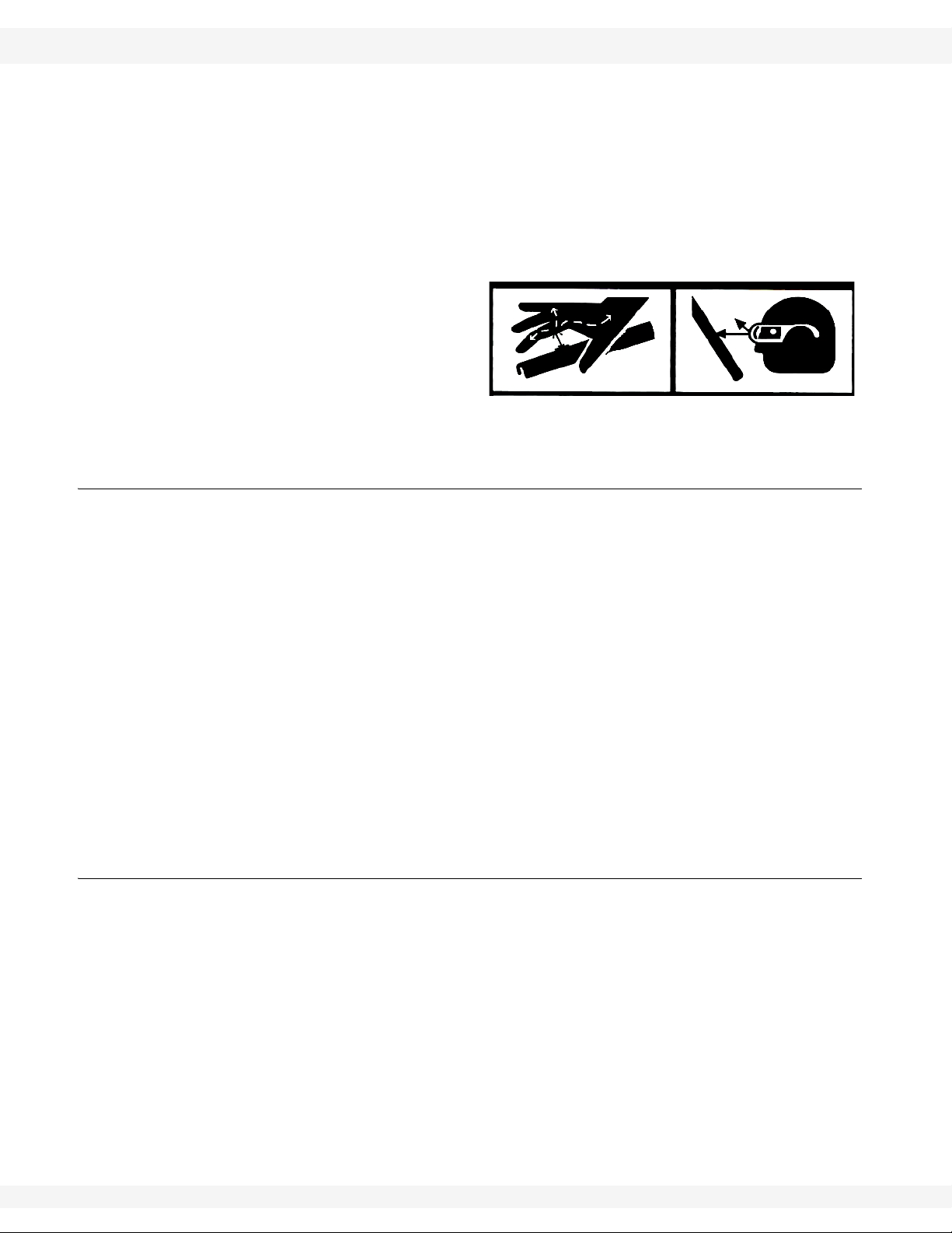
• Wear proper hand and eye protection when searching for a high-pressure
hydraulic leak. Do not use hands. Use a piece of wood or cardboard as a
backstop to isolate and identify a leak.
• If injured by a concentrated
high-pressure stream of
hydraulic fluid, seek medical
attention immediately. Serious infection or toxic reaction
can develop from hydraulic
fluid piercing the skin surface.
2.6. PTO DRIVELINE SAFETY
• To prevent serious injury or death:
• Keep body, hair, and clothing away from rotating PTO driveline.
• Do not operate equipment unless all driveline, tractor, and equipment shields
are in place and in good working order.
• Make certain the driveline shields turn freely on driveline.
• Make certain the driveline is securely attached at both ends.
• Do not exceed operating speed of 540 rpm.
• Keep u-joint angles small and equal. Do not exceed maximum recommended
length for PTO driveline.
• Do not exceed manufacturer’s recommended operating length.
• Set the tractor brake and block wheels on the tractor and the implement to
insure proper spacing of the PTO shaft at all times.
• Make sure driveline is properly secured to prevent damage during transport.
2.7. TIRE SAFETY
• Failure to follow proper procedures when mounting a tire on a wheel or rim
can produce an explosion that may result in serious injury or death.
• Do not attempt to mount a tire unless you have the proper equipment and
experience to do the job.
• Have a qualified tire dealer or repair service perform required tire maintenance.
• When replacing worn tires, make sure they meet the original tire specifications. Never undersize the replacement tire.
• Do not weld to the tire rim with the tire mounted on the rim. This action may
cause an explosion which could result in serious injury or death.
• Inflate tires to the manufacturers's recommended pressure.
16 30787 R1

WHEATHEART - X13 SERIES AUGERS 2. SAFETY
X1374, X1384, X1394 2.8. TRANSPORT SAFETY
2.8. TRANSPORT SAFETY
• Ensure tires are inflated to the tire manufacturer’s recommended pressure.
• Make sure that all lights and reflectors required by the local highway and
transport authorities are in place, are functioning, and can be seen clearly by
all overtaking and oncoming traffic.Check with local authorities regarding
transportation of agricultural equipment on public roads. Obey all applicable
laws and regulations.
• Be sure the unit is hitched securely to the towing vehicle.
• Do not allow riders while transporting.
• Display a Slow Moving Vehicle (SMV) emblem when transporting below 15
mph (24 km/h).
• Use hazard-warning flashers when transporting with a tractor unless prohibited.
• Keep to the right and yield the right-of-way to allow faster traffic to pass.
• Never transport faster than the road terrain or conditions will safely allow.
• Use caution when turning corners or meeting traffic.
• Use caution when approaching height-limiting objects.
• Be especially careful when transporting during times of limited visibility (rain,
snow, fog, dusk, or at night). If you can, wait for a more appropriate time to
move the equipment.
• Do not transport auger on a slope greater than 20°—the auger may overturn.
• The manual winch must be in the locked position. To lock, turn handle clockwise until you hear two clicks. Also ensure that the locking pin and clips are in
place on the hopper lift arm.
2.9. STORAGE SAFETY
• Store in an area away from human activity.
• Do not permit children to play on or around the stored machine.
2.10. MAINTENANCE SAFETY
• Shut off and disable the power source before working on the machine.
• Ensure service area is clean and dry.
• Ensure electrical outlets and tools are properly grounded.
• Use proper tools for the job and wear appropriate safety gear.
• Ensure there is adequate lighting to perform the job safely.
• Place chocks in front and behind the wheels to prevent the machine from rolling.
• Use extra caution when cleaning and servicing augers because flighting
edges can be sharp.
• Follow proper procedures when mounting a tire on a rim. If in doubt, have a
qualified tire repair service perform the required maintenance.
• Install and secure all guards after maintenance work is completed.
30787 R1 17
2. SAFETY WHEATHEART - X13 SERIES AUGERS
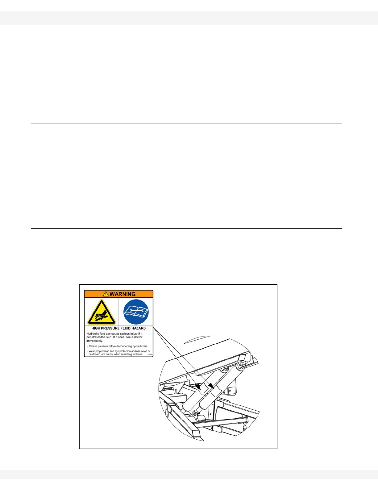
DECAL #17100
2.11. SAFETY DECALS X1374, X1384, X1394
2.11. SAFETY DECALS
• Keep safety decals clean and legible at all times.
• Replace safety decals that are missing or have become illegible. See decal
location figures that follow.
• Replaced parts must display the same decal(s) as the original part.
• Safety decals are available from your distributor, dealer, or factory.
2.11.1. DECAL INSTALLATION
1. Decal area must be clean and dry, with a temperature above 50°F (10°C).
2. Decide on the exact position before you remove the backing paper.
3. Align the decal over the specified area and carefully press the small portion
with the exposed sticky backing in place.
4. Slowly peel back the remaining paper and carefully smooth the remaining
portion of the decal in place.
5. Small air pockets can be pierced with a pin and smoothed out using the sign
backing paper.
2.11.2. SAFETY DECAL LOCATIONS
Replicas of the safety decals that are attached to the equipment are shown in the
figure(s) that follow. Proper safety procedures require that you familiarize
yourself with the various safety decals and the areas or particular functions that
the decals apply to, as well as the safety precautions that must be taken to avoid
serious injury, death, or damage.
18 30787 R1
Figure 2.2
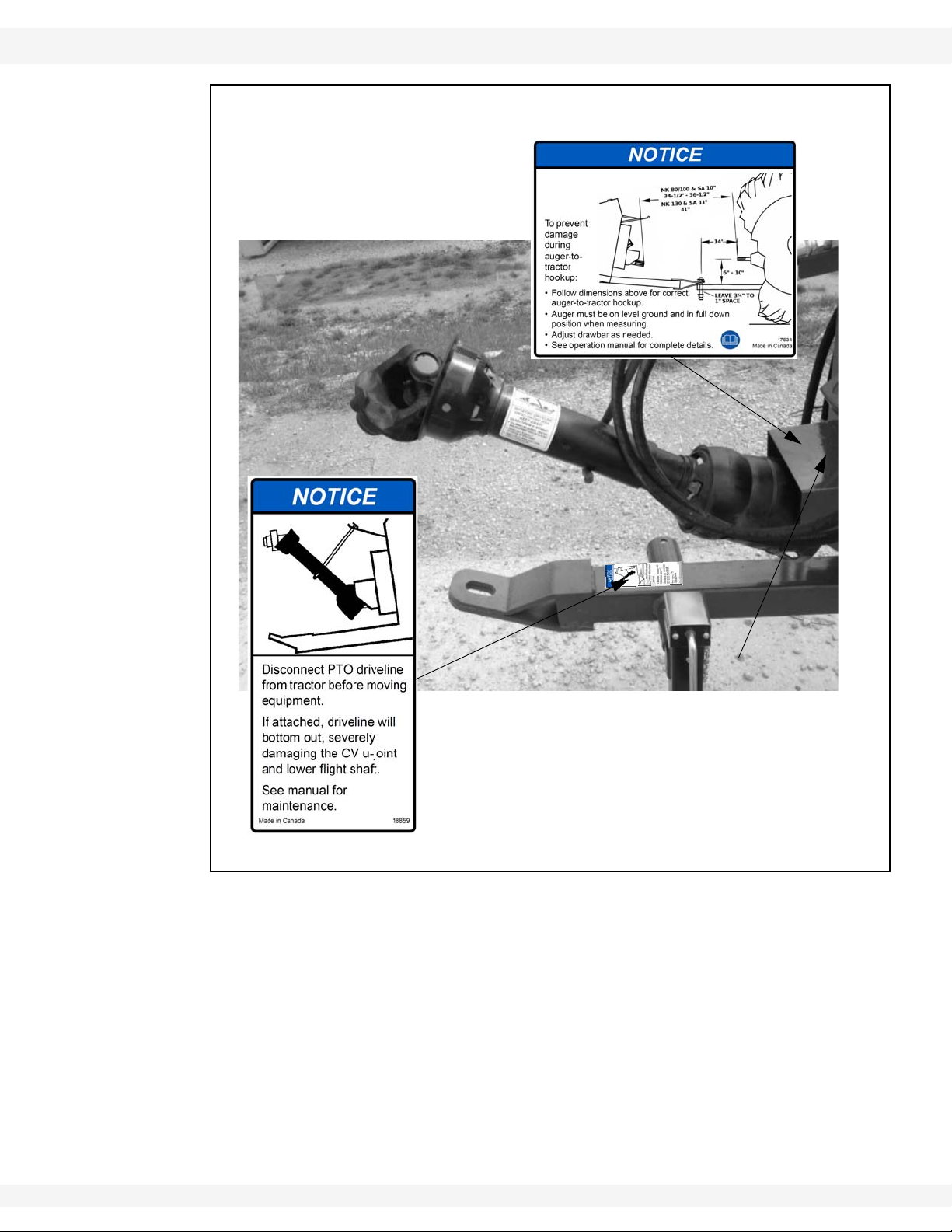
WHEATHEART - X13 SERIES AUGERS 2. SAFETY
DECAL #18859
DECAL #17531
X1374, X1384, X1394 2.11. SAFETY DECALS
30787 R1 19
Figure 2.3
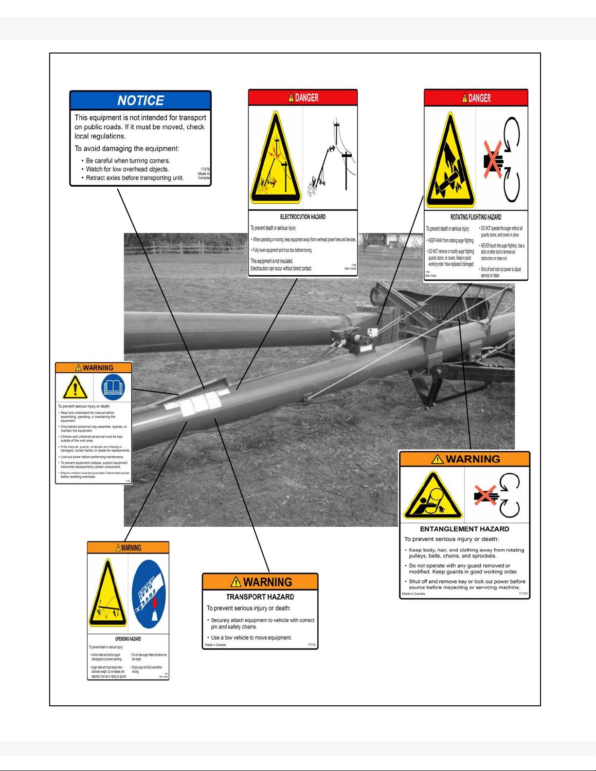
2. SAFETY WHEATHEART - X13 SERIES AUGERS
DECAL #17098
DECAL #17097
DECAL #17096
DECAL #17101
DECAL #17113
DECAL # 17378
DECAL #17398
(LOCATED ON HOPPER
CHAIN GUARD)
2.11. SAFETY DECALS X1374, X1384, X1394
Figure 2.4
20 30787 R1
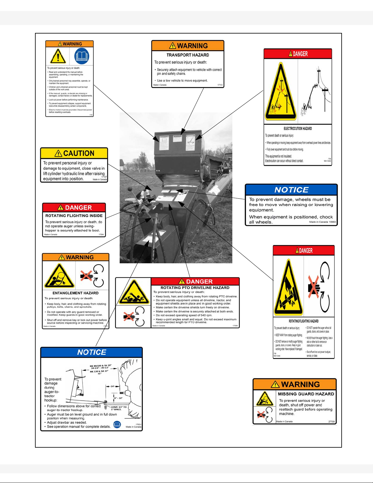
WHEATHEART - X13 SERIES AUGERS 2. SAFETY
DECAL #17099
DECAL #17107
DECAL #19960
DECAL #17531
DECAL #17098
DECAL #17101
DECAL #17094
DECAL #17096
DECAL #17113
DECAL #17398
PLACED ON MACHINE BEHIND
GUARD
DECAL #27709
X1374, X1384, X1394 2.11. SAFETY DECALS
Figure 2.5
30787 R1 21

2. SAFETY WHEATHEART - X13 SERIES AUGERS
DECAL # 27516
2.11. SAFETY DECALS X1374, X1384, X1394
Figure 2.6
22 30787 R1

WHEATHEART - X13 SERIES AUGERS 3. ASSEMBLY
WARNING Before continuing, ensure you have read and underst and the relevant information
in the safety section. Safety information is provided to help prevent serious injury, death, or
property damage.
X1374, X1384, X1394 3.1. GENERAL ASSEMBLY
3. Assembly
Familiarize yourself with all the sub-assemblies and hardware making up the
auger. Do not take chances with safety. The components are large, heavy, and
can be hard to handle. Be sure to use the proper tools, stands, jacks, and hoists
for the job.
Important: These instructions are written on the assumption that 2 or more people will be
available for the assembly procedure. Because of the weight, it is unwise to
attempt assembly of the auger alone.
Note: When tightening all fasteners, see the Appendix for proper torque specifications.
3.1. GENERAL ASSEMBLY
1. Select an assembly area that is level, has a firm or hard surface and is free of
debris. Be sure it is large enough to allow access from all sides when the
components are being assembled.
2. If assembling inside a building, be sure the ceiling is at least 14’ (4.27 m) high
to provide clearance when installing the undercarriage
3. Bring all the tools, blocks, stands, jacks, and hoists to the assembly area
before starting.
4. The following tools and equipment are required to assemble the machine:
• 11-14 support stands (tube section supports, three per tube)
• Four saw horses (1200 lb / 544.3 kg bearing capacity)
• One Standard socket set and wrench set
• One torque wrench
• One standard 25’ (7.62 m) tape measure
• One 2’ level
• One 8” level magnetic
• Two C-clamps or vise grips
• One picker with minimum reach of 12’ (3.66 m) 4000-6000 lb
(1 814 - 2 722 kg) lifting capacity
• One 100’ (30 m) measuring tape
• One tire gauge
• One tire chuck
• 6-10 wood blocks (2x4's or smaller)
• Grease
• Impact wrench and sockets
• Two or more steel punches (for aligning bolt holes)
30787 R1 23

3. ASSEMBLY WHEATHEART - X13 SERIES AUGERS
3.1. GENERAL ASSEMBLY X1374, X1384, X1394
See Table 3.1. for a list of assembly procedures.
Table 3.1. X13 Auger Assembly Procedures
Procedure Page
Identify Auger Tube Sections page 25
Assemble the Main Auger Tube page 28
Install the Boot on the Auger tube page 29
Install the Boot Tow Bar page 32
Install the Discharge Spout page 33
Set the Thrust Adjuster page 33
Apply Logo and Model Decals page 34
Auger Tube Truss Assembly page 35
Assemble the Auger Frame page 49
Installing the Hydraulic Cylinders page 56
Assemble Wheel Hubs and Install Tires page 57
Attaching the Auger Tube to the Frame page 58
Connecting Hydraulic Hose to Cylinders page 61
Install Low Profile Intake Hopper page 65
Installing the Hopper Lift Arm and Winch page 69
Install the Hitch Jack page 72
Connecting the PTO Driveline page 72
Auger-to-Tractor Hookup page 74
24 30787 R1
WHEATHEART - X13 SERIES AUGERS 3. ASSEMBLY
X1374, X1384, X1394 3.2. IDENTIFY AUGER TUBE SECTIONS
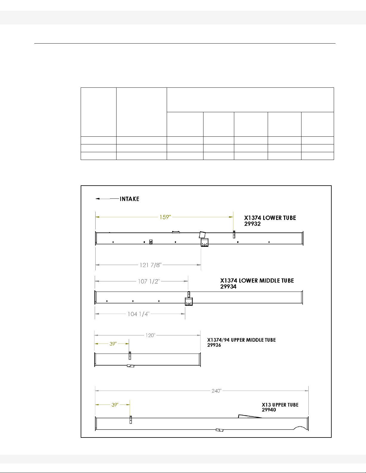
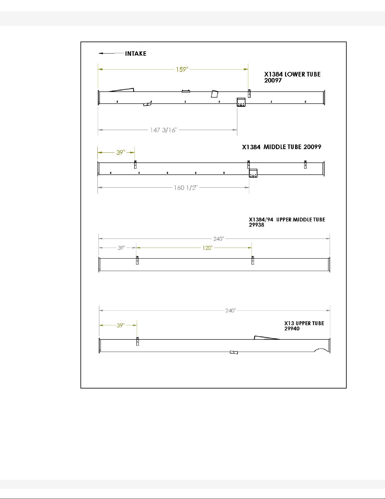
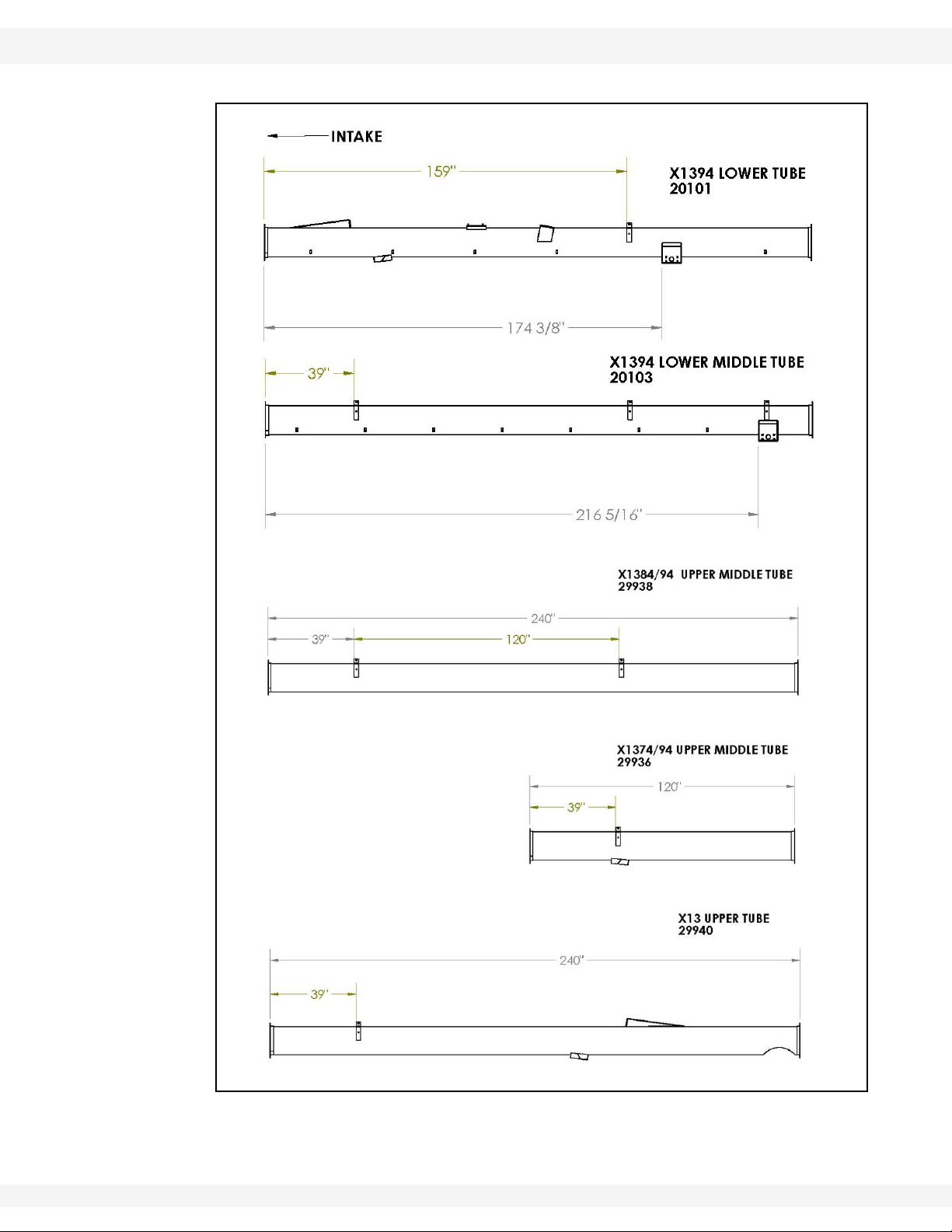
3.2. IDENTIFY AUGER TUBE SECTIONS
Note: See Table 3.2 for the number of tube sections and their part numbers and
lengths. Assemble the auger starting with the discharge section and working
toward the intake section.
Table 3.2 Tube Section Information, by Model
Tube Bundle Part Numbers
Total Number
Model
X130-74 4 29932* 29934* -- 29936** 29940*
X130-84 4 20097* 20099* 29938* -- 29940*
X130-94 5 20101* 20103* 29938* 29936** 29940*
*20’ [6.10 m]
**10’ [3.05 m]
of Tube
Sections
(Starting from Boot [intake] moving toward
Discharge)
Lower
Tube
Lower
Middle
Tube
Middle
Tube
Upper
Middle
Tube
Upper
Tube
Figure 3.1 X130-74 Auger Tube Sections
30787 R1 25
3. ASSEMBLY WHEATHEART - X13 SERIES AUGERS
3.2. IDENTIFY AUGER TUBE SECTIONS X1374, X1384, X1394
Figure 3.2 X130-84 Auger Tube Sections
26 30787 R1
WHEATHEART - X13 SERIES AUGERS 3. ASSEMBLY
X1374, X1384, X1394 3.2. IDENTIFY AUGER TUBE SECTIONS
Figure 3.3 X130-94 Auger Tube Sections
30787 R1 27
3. ASSEMBLY WHEATHEART - X13 SERIES AUGERS
1/2” LOCKNUT
7/16” X 1-1/4” BOLTS
7/16”
1/2” X 4” BOLT
LOCKNUTS
3.3. ASSEMBLE THE MAIN AUGER TUBE X1374, X1384, X1394
3.3. ASSEMBLE THE MAIN AUGER TUBE
See Table 3.3. for a list of hardware required to assemble the main auger tube.
Table 3.3. Parts Required, Assembling the Main Auger Tube
Part Number Description X130-74 X130-84 X130-94
18974 1/2” x 4” bolts 3 3 4
17750 1/2” locknuts 3 3 4
18698 7/16'' X 1-1/4'' bolts 48 48 64
17593 7/16” locknuts 48 48 64
1. Align tube sections on a series of support stands, placing a support stand at
the end of each tube. If possible, make sure that support stand height is
equal across all tubes to ensure that tubes are level with each other.
Otherwise, use some form of shim to keep the tubes level across all of the
support stands.
Important: Always strap tubes to the support stands to prevent the tubes from rolling off the
stands and onto the floor.
2. Working from the spout end (upper tube) to the discharge end (lower tube),
connect the tubes together as shown in Figure 3.4, as described below:
a. Align flightings to ensure a continual spiral of auger surface, and connect
flight shafts with 1/2” x 4” bolts and 1/2” locknuts.
b. As flight shafts are connected, slide tube sections together and secure with
7/16'' X 1-1/4'' GR8 bolts and 7/16” locknuts.
28 30787 R1
Figure 3.4 Connecting Auger Tubes and Flights
WHEATHEART - X13 SERIES AUGERS 3. ASSEMBLY
1/2” LOCKNUT
1/2” X 4” GR8 BOLT
X1374, X1384, X1394 3.4. INSTALL THE BOOT ON THE AUGER TUBE
3.4. INSTALL THE BOOT ON THE AUGER TUBE
.\
See Table 3.4. for a list of parts required to install the boot on the auger tube.
Table 3.4. Parts Required, Installing the Boot on the Auger Tube
Part Number Description Amount
29991 X13 boot assembly 1
29999 X13 boot-tube attach plate 1
18698 7/16” X 1-1/4” bolts 21
17593 7/16” locknuts 21
WARNING
Components are heavy and create a crushing
hazard if improperly handled. Be sure to use
proper hoisting equipment and procedures,
and ensure lifting apparatus is secure. Lock
out the lifting apparatus before working
around or under the raised components;
failure to do so may cause serious personal
injury.
Note: The gearbox is sent from the factory filled half way with EP90 gear oil. Before
further assembly, check oil level to make certain the gearbox is half full. Add oil if
necessary. Do not use grease.
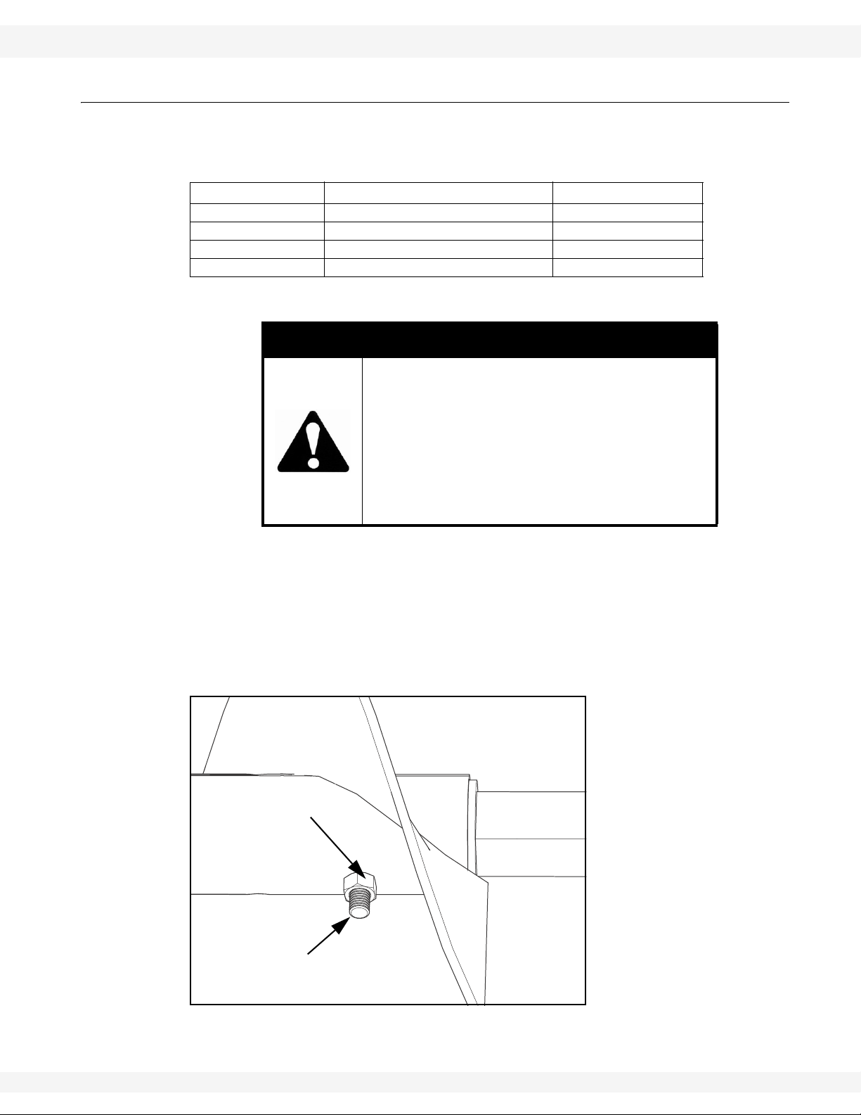
1. The boot flighting comes pre installed on the end of the lower tube flighting
shaft (See Figure 3.5). Ensure that the flighting is fastened with a
1/2'' X 4” GR8 bolt and 1/2” locknut before proceeding.
30787 R1 29
Figure 3.5 Check Boot Flight Bolt and Nut
3. ASSEMBLY WHEATHEART - X13 SERIES AUGERS
TUBE FLANGE
BOOT-TUBE
TOP BOOT-TUBE
ATTACH PLATE
BOTTOM BOOT-TUBE ATTACH
PLATE BOLTS (3)
BOLTS (2)
ATTACH PLATE
3.4. INSTALL THE BOOT ON THE AUGER TUBE X1374, X1384, X1394
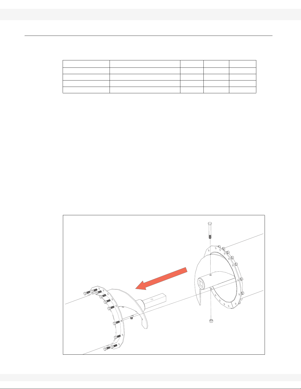
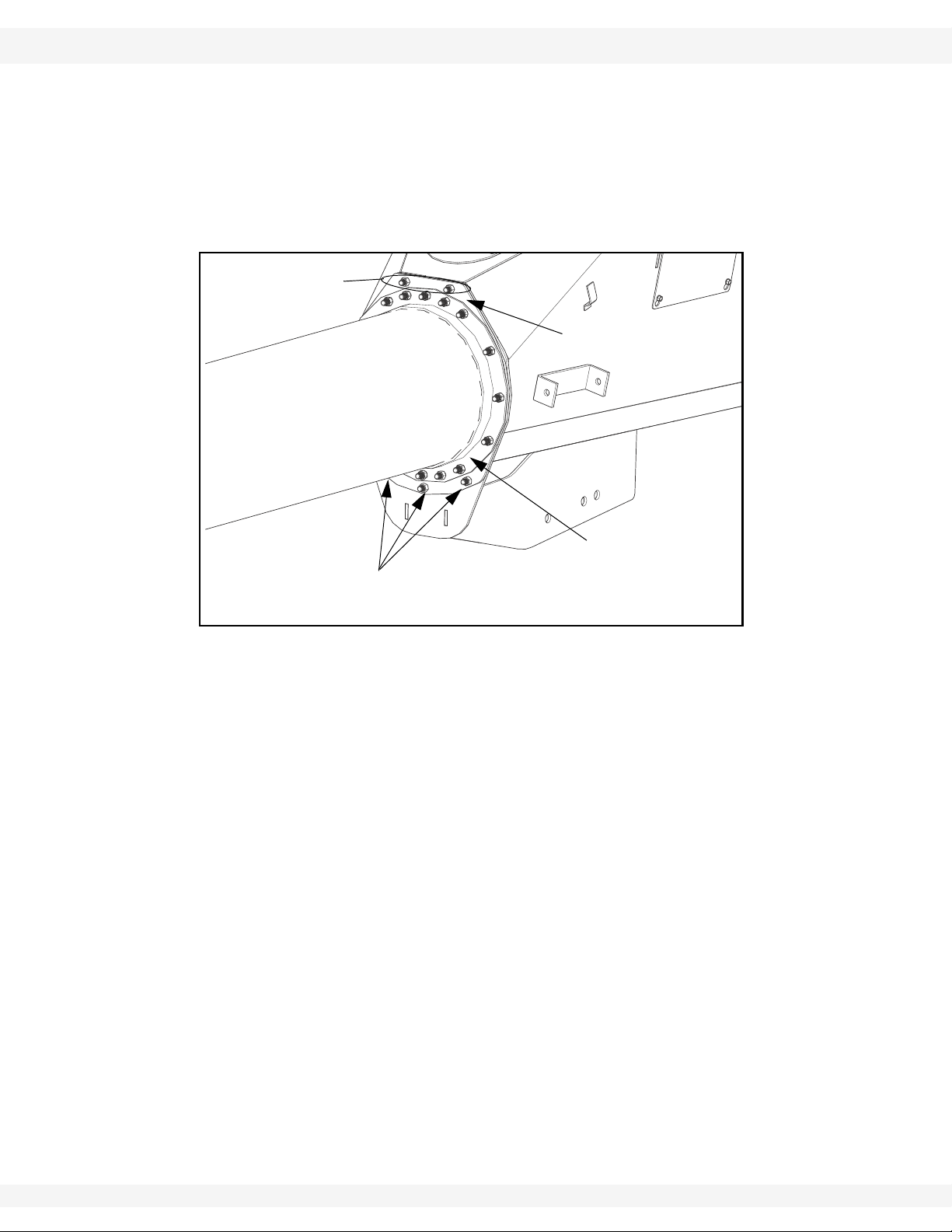
2. Slip the boot-tube attach plate over the boot flighting. Position the plate with
flat edge facing up (see Figure 3.6), and fasten with five 7/16” x 1-1/4” GR8
bolts inserted from the boot side of the flange and 7/16” locknuts.
3. Slip the boot assembly over the lower flighting shaft and attach it to the
flange on the lower tube with 14 7/16” x 1-1/4” GR8 bolts and
7/16” locknuts (see Figure 3.6).
Figure 3.6 Installing the Boot on the Auger Tube
4. Insert the remaining boot attach plate bolts, secure with locknuts, and tighten
all flange and boot attach plate nuts fully (do not overtighten).
30 30787 R1

WHEATHEART - X13 SERIES AUGERS 3. ASSEMBLY
2” RIM WASHER
DRIVE
5/8” X 2” BOLTS
5/8” LOCKNUTS
LOWER
SPROCKET
SQUARE KEY
LOCK COLLAR
LOWER BEARING
CHAIN
AND FLANGE
X1374, X1384, X1394 3.5. INSTALL BOOT BEARING, LOWER SPROCKET, AND DRIVE CHAIN
3.5. INSTALL BOOT BEARING, LOWER SPROCKET, AND DRIVE CHAIN
See Table 3.5. for a list of part s required to install the boot bearing, lower
sprocket, and drive chain.
Table 3.5. Parts Required, Installing the Boot Bearing, Lower Sprocket,
and Drive Chain
Part Number Description Amount
20084 2” rim washer 1
20015 2” lower bearing, 4-bolt flange, lock collar 1
18541 Square key, 3/8" x 3-3/8" 1
18525 Lower sprocket, 80b18 x 1-3/4” 1
19781
19134
19991 5/8” x 2” bolts 4
19600 5/8” locknuts 4
1. Install the lower sprocket as follows:
a. Slide the 2” wide rim flat washer onto lower flight shaft.
b. Slide the lower bearing over the flighting shaft, and bolt it loosely in place
with four 5/8” X 2” bolts and 5/8” locknuts.
Drive chain (80b37 roller chain)
#80 chain connector
1
1
c. Ensure that the flight shaft shoulder is seated against washer and lower
bearing.
d. Position the lock collar tightly against the bearing, then tighten the collar set
screw against the flighting shaft.
e. Install the 3/8” x 3-3/8” square key on the flighting shaft, then slide the
lower sprocket onto the flighting shaft. Align lower sprocket face with upper
sprocket face using a straight edge, then tighten set screws.
Figure 3.7 Installing Boot Bearing, Sprocket, and Chain
30787 R1 31

3. ASSEMBLY WHEATHEART - X13 SERIES AUGERS
3/4” X 5-1/2” BOLT
3/4” X 3-1/2” X 5” SQUARE U-BOLT
3/4” LOCKNUTS
BOOT
T
O
W
B
A
R
AND 3/4” LOCKNUT
CHANNEL
3.6. INSTALL THE BOOT TOW BAR X1374, X1384, X1394
Note: It is recommended you use a thread locking compound that meets or exceeds
Loctite Blue© on all set screws.
Important: To prevent premature failure of the lower bearing, ensure it has been assembled
in the correct sequence.
2. Loop the drive chain around upper and lower sprockets. Push the flighting
shaft down until the chain is tensioned to within about 1/4” deflection, then
tighten the 4 bolts on the bottom bearing. Oil the chain lightly.
Note: For ease of PTO installation, sprocket shield should be attached after the instal-
lation of the PTO driveline. See “Connecting the PTO Driveline” on page 72.
3.6. INSTALL THE BOOT TOW BAR
See Table 3.6. for a list of parts required to install the boot tow bar.
Table 3.6. Parts Required, Installing the Boot Tow Bar
Part Number Description Amount
29983 Tow bar
29997 3/4” x 5-1/2” bolt
19601 3/4” locknut
28487 3/4” x 3-1/2” x 5” square U-bolt
1
1
3
1
1. Insert the tow bar into the boot channel, and secure the back end loosely with
a 3/4” x 5-1/2” bolt and 3/4” locknut through the back hole in the boot channel
(under the boot).
2. Tightly secure the middle of the tow bar in the channel with a
3/4” x 3-1/2” x 5” square U-bolt and two 3/4” locknuts.
3. Fully tighten the 3/4” nut on the 3/4” x 5-1/2” bolt.
Figure 3.8 Installing the Boot Tow Bar
32 30787 R1

WHEATHEART - X13 SERIES AUGERS 3. ASSEMBLY
SPOUT
7/16” X 1-1/4” BOLTS [18698]
7/16” LOCKNUTS
[17593]
Figure 3.10
X1374, X1384, X1394 3.7. INSTALL THE DISCHARGE SPOUT
3.7. INSTALL THE DISCHARGE SPOUT
1. Align the discharge spout over the opening in the upper tube.
2. Attach the discharge spout with two 7/16” x 1-1/4” GR 8 bolts [18698] and
7/16” locknuts [17593].
Figure 3.9 Installing the Discharge Spout
3.8. SET THE THRUST ADJUSTER
1. Remove the upper bearing lock collar (if necessary).
2. Slide the lock collar and bushing onto the shaft and attach the 1-1/2” nut.
3. Turn the nut until it is snug against the bushing, then turn it so that the shaft
moves an additional 1/4” away from the top plate.
4. Secure the lock collar and tighten the set screw.
5. Install the cover over the two longer 5/8” bolt s. Secure with two
5/8” whiz-nuts.
30787 R1 33

3. ASSEMBLY WHEATHEART - X13 SERIES AUGERS
LOWER MIDDLE TUBE
UPPER TUBE
WHEATHEART LOGO, CENTRED ON SIDE OF UPPER TUBE
AUGER MODEL
(DISCHARGE SIDE)
3.9. APPLY LOGO AND MODEL DECALS X1374, X1384, X1394
3.9. APPLY LOGO AND MODEL DECALS
1. Prepare surface by cleaning
thoroughly with soap and water.
Surface must be clean and free of dirt,
grime, rust and oil. To clean oily
surface, wipe with clean cloth and
solvent cleaner or isopropyl alcohol.
2. Position the decal on the tube and
apply masking tape along the top,
creating a gate hinge. Figure A
demonstrates.
3. Remove backing paper from decal 6"
from the top and use the squeegee to
adhere decal to the tube, as seen in
Figure B. Start at the top center of the
decal and work your way outward both
left and right using overlapping
strokes.
4. As you work your way down the decal,
peel back the backing paper 6" at a
time. Repeat Step 3 until the entire
decal has been applied to the tube.
See Figure C as an example.
5. Once the entire decal has been
properly adhered to the tube, carefully
remove tape.
6. Inspect the decal for air pockets; if
found, remove them by punching a tiny
hole with a pin and then squeegee the surface flat.
7. Squeegee the corners and edges of the decal to ensure proper adhesion and
to prevent premature peeling.
34 30787 R1
Figure 3.11 Logo and Model Decal Locations

WHEATHEART - X13 SERIES AUGERS 3. ASSEMBLY
X1374, X1384, X1394 3.10. AUGER TUBE TRUSS ASSEMBLY
3.10. AUGER TUBE TRUSS ASSEMBLY
• X130-74 augers use a double cable truss on the top of the auger tube “X13074 Auger Tube Truss Assembly” on page 35).
• X130-84 and X130-94 augers use a combination of rigid tube trussing on top
of the auger tube and cable trussing on the sides of the auger tube (see
“X130-84/X130-94 Auger Tube Truss Assembly” on page 40).
3.10.1. X130-74 AUGER TUBE TRUSS ASSEMBLY
INSTALL THE X130-74 CABLE BRIDGES
See Table 3.7. for a list of part s required to install the X130-74 cable bridges.
See Figure 3.12 for a detailed diagram.
Table 3.7. Parts Required, Installing X130-74 Cable Bridges
Part Number Description Amount
20017 High truss tower
18988WH Low truss towers
20105 Truss cable attach bracket
18698 7/16” x 1-1/4” GR8 bolts
17593 7/16” locknut
1
2
1
8
8
1. Fasten the three truss towers to the provided brackets (welded to the
appropriate tube sections):
a. Position the high truss tower in the centre position, and position the low
truss towers toward the spout and intake ends.
b. Use two 7/16” x 1-1/4” GR8 bolts and 7/16” locknuts to fasten each cable
bridge in place.
2. Install the truss cable attach bracket as shown in the diagram, using two
7/16” x 1-1/4” GR8 bolts and 7/16” locknuts.
30787 R1 35

3. ASSEMBLY WHEATHEART - X13 SERIES AUGERS
TRUSS CABLE
HIGH TRUSS
LOW
ATTACH BRACKET
7/16” LOCKNUTS
7/16” X 1-1/4” BOLTS
7/16” X 1-1/4” BOLTS
7/16” LOCKNUTS
TRUSS TOWER
LOW
TRUSS TOWER
TOWER
3.10. AUGER TUBE TRUSS ASSEMBLY X1374, X1384, X13 94
Figure 3.12 X130-74 Truss Towers and Truss Cable Attach Brackets
36 30787 R1

WHEATHEART - X13 SERIES AUGERS 3. ASSEMBLY
X1374, X1384, X1394 3.10. AUGER TUBE TRUSS ASSEMBLY
INSTALL THE X130-74 TRUSS CABLES
There are two cable runs on the X130-74, a long cable run between the upper
tube and the lower tube, and a short cable run between the lower tube and the
upper middle tube:
• The first (short) run is made up of a single 73’ cable.
• The second (long) run is made up of two separate cables: one 85’ 6” long
and one 36’ long.
See Table 3.8. for a list of parts required to install the X130-74 truss cables. See
Figure 3.13 for a detailed diagram.
Table 3.8. Parts Required, X130-74 Truss Cables
Part Number Description Amount
27502 73’ cable 1
27503 85’ 6” cable 1
20090 36’ cable 1
17464 Turnbuckle 2
19331 1/2” eyebolts 6
18990 3/8” cable clamps 12
19333 5/16” cable clamps 10
17750 1/2” locknuts 6
Note: X130-74 truss cables should be tightened to provide a 1” upward bow in the
auger tube, as measured at the auger tube spout end.
1. Ensure that the tube is supported by at least 3 stands (one at each end and
one in the middle).
2. Shim the stands (use wood blocks) at the spout end approximately
7” (17.8 cm) higher than the other stands to provide the required curve.
3. For the first (short) cable run, attach an eyebolt to each end of the 73’ truss
cable using two 3/8” cable clamps, doubling-back about
12” (30.5 cm) of cable.
4. Connect one of the eyebolts to one side of the truss cable attach bracket
using a 1/2” locknut threaded fully onto the eyebolt shaft, but not further than
1/4”.
5. Pull the cable:
• over the high (middle) truss tower,
• under the tube and around the middle cable return bracket,
• back over the middle cable bridge,
• and back to the truss cable attach bracket
6. Connect the second eyebolt on the remaining end of the cable to the other
side of the truss cable attach bracket using a 1/2” locknut threaded fully onto
the eyebolt shaft, but not further than 1/4”.
7. For the second (long) cable run:
• Thread the 36’ cable through the cable guide on the underside of the
lower tube, and pull the cable through until there is an equal length of
cable on each side of the tube.
30787 R1 37

3. ASSEMBLY WHEATHEART - X13 SERIES AUGERS
3.10. AUGER TUBE TRUSS ASSEMBLY X1374, X1384, X13 94
• Attach eyebolts to the ends of the 36’ cable [20090] with two 3/8” cable
clamps [18990], using about 10" (25.4 cm) - 12" (30.5 cm) of cable.
Tighten securely.
• Insert each eyebolt into a separate turnbuckles, and secure by threading
on a 1/2” locknut fully onto the eyebolt shaft, but not further than 1/4”.
8. Starting at the lower tube, pull the 85’6” cable:
• over the low and high truss towers (fasten loosely with 5/16” cable
clamps)
• under the tube and around the cable return bracket at the upper tube (fasten loosely with a 5/16” cable clamp)
• back over the truss towers on the opposite side (fasten loosely with 5/16”
cable clamps), providing equal lengths of cable on both sides of the tube.
Important: The 85’ 6” cable must be installed on the outside of the high (middle) truss tower .
9. Insert an eyebolt into the unconnected side of each of the turnbuckles (whose
other sides are connected to the 36’ cable), and secure by threading on a 1/2”
locknut fully onto the eyebolt shaft, but not further than 1/4”.
10. Thread the end of each side of the 85’6” cable through the appropriate
turnbuckle eyebolt, and pull the cable snug. Double-back the cable and
secure in place with 2 cable clamps doubling-back about 12”
(30.5 cm) of cable.
Note: If there isn’t enough cable, loosen the clamps on the opposite eyebolt and adjust
the cable. Retighten clamps.
Important: Truss cables must be tightened to provide a 1” upward bow on the spout end.
Blocks and shims can be used to elevate the spout to help create the required
bow while tightening the truss cables, but the 1” bow is measured with the spout
end unsupported.
11. Tighten the eyebolts on the second (long) cable run evenly to take the
remaining slack out of the truss cable. Once this cable run is tightened,
repeat for the first (short) cable run.
12. Check for proper side-to-side alignment and then tighten the cable clamps on
the cable bridges and the cable return brackets.
38 30787 R1

WHEATHEART - X13 SERIES AUGERS 3. ASSEMBLY
1
/
2
”
L
O
C
K
N
U
T
E
Y
E
B
O
L
T
C
A
B
L
E
G
U
I
D
E
S
3
/
8
”
C
A
B
L
E
C
L
A
M
P
S
E
Y
E
B
O
L
T
S
T
U
R
N
B
U
C
K
L
E
3
/
8
”
C
A
B
L
E
C
L
A
M
P
S
C
A
B
L
E
R
E
T
U
R
N
5
/
1
6
”
C
A
B
L
E
C
L
A
M
P
B
R
A
C
K
E
T
7
3
’
C
A
B
L
E
8
5
’
6
”
C
A
B
L
E
5
/
1
6
”
C
A
B
L
E
C
L
A
M
P
S
5
/
1
6
”
C
A
B
L
E
C
L
A
M
P
3
6
’
C
A
B
L
E
X1374, X1384, X1394 3.10. AUGER TUBE TRUSS ASSEMBLY
Figure 3.13 X130-74 Truss Cable Installation
30787 R1 39

3. ASSEMBLY WHEATHEART - X13 SERIES AUGERS
3.10. AUGER TUBE TRUSS ASSEMBLY X1374, X1384, X13 94
3.10.2. X130-84/X130-94 AUGER TUBE TRUSS ASSEMBLY
INSTALL X130-84/X130-94 TRUSS TOWERS AND TRUSS TUBES
See Table 3.9. for a list of part s required to install the X130-84/X130-94 truss
towers and truss tubes, as well as for figure references that apply to the
diagrams below.
• For the X130-84 models, see Figure 3.14 and Figure 3.15.
• For the X130-94 models, see Figure 3.16 and Figure 3.17.
Note: Due to rigidity of the tubular trussing, X130-84 and X130-94 truss tubes should
be tightened to provide only a small upward bow (approximately 1”) at the auger
tube spout end.
Note: When assembling the truss system, do not fully tighten any bolts until specifi-
cally instructed to do so.
1. Attach p airs of low and high truss tower brackets to the truss-attach
brackets welded to auger tube, using four of 7/16” x 1-1/4” bolts and locknuts
per pair.
2. Thread a 1” hex nut as far as possible onto the threaded rod end of a long
adjuster tube.
3. Insert the threaded rod end of the long adjuster tube into the truss tube
anchor, and bolt the opposite end to a truss joiner plate that has been first
bolted to the adjacent low truss tower.
4. Thread an second 1” nut a short distance onto the threaded rod end of the
long adjuster tube.
5. Work from one end of the tube toward the centre and install:
a. Install tube truss joiner plates between truss tower pairs.
Note: Truss towers connect to their truss joiner plate using a 1/2” x 1-1/2” bolt and
locknut.
Note: T russ joiner plates must be oriented correctly when installed. Always ensure that
the three 7/16” bolt holes should be closest to the discharge spout, and the 5/8”
bolt hole should be closest to the boot.
b. long tubes between truss joiner plates bolted between high truss pairs;
Note: Truss tubes connect to truss joiner plates using three 7/16'' x 1-3/4'' bolts and
locknuts where there are three bolt holes on the end of the tube, and with a
single 5/8'' x 2'' bolt and locknut where there is a single bolt hole at the end of the
tube. A four-hole truss adjuster plate is required.
c. cross-brace tubes between truss joiner plates and tabs between truss
tower pairs (keep cross-brace bolts loose until Step 13.)
Note: A single cross-brace tube is positioned between the low truss towers and
adjacent high truss towers. Two cross braces tubes are required between two
adjacent
high truss towers.
Note: Cross-brace tubes use 1/2” x 1-1/2” bolts and locknuts at the truss joiner plate
and at the tab between truss tower pairs.
6. Install the tube adjust plate, and attach the short adjuster tube to it as follows:
a. bolt the tube adjust plate between the high truss tower bracket pair (see
the diagram for your specific model);
40 30787 R1

WHEATHEART - X13 SERIES AUGERS 3. ASSEMBLY
X1374, X1384, X1394 3.10. AUGER TUBE TRUSS ASSEMBLY
b. thread a 1” nut fully onto the threaded rod end of a short adjuster tube,
then insert threaded rod into the truss tube adjuster plate;
c. thread a second 1” nut a short distance onto the threaded rod.
7. Repeat the above process for the discharge side of the tube.
8. Ensure that the 1” nuts on the long and short adjuster tubes are loose. Pairs
of 1” nuts on adjuster tubes (short and long) should be rotated away from
each other to ensure that the nuts are not placing any tension on the truss
tubes or truss brackets.
9. Ensure that auger tube sections are supported in such a way that the tube is
as straight as possible. Use additional supports, shims, and blocks as
required.
10. Long adjust tubes:
• Rotate the 1" hex nut pairs on both long adjust tubes toward each other
until they lock together tightly on either side of their respective truss tube
anchors (spout end and boot end).
• When fully tightened, the truss tower brackets should remain positioned at
a 90 degree angle with respect to the auger tube, and should not lean to
either side.
11. Short adjust tubes:
• Tighten the two 1" hex nuts on the inside of the tube adjust plate until
there is enough tension in the truss tubes to create a slight upward bow in
the tube (1” as measured from the tube support and the top of the tube,
just before the tube cap).
• When tightening the nuts, alternate between the two nuts frequently
enough to ensure that they are tightened equally, and that the same
amount of threaded rod is exposed on each side.
• Rotate the remaining 1” nuts on the short adjuster tubes until they lock
tightly on each side of the tube adjust plate.
12. Install pairs of cross-brace clamps where the cross-brace tubes cross in an
“X” pattern using two 7/16” x 1-1/4” bolts and locknuts, and tighten fully.
13. Fully tighten cross-brace tube nuts at the truss joiner plates and at the tab
between truss tower pairs.
14. Check that all nuts are firmly tightened.
30787 R1 41

3. ASSEMBLY WHEATHEART - X13 SERIES AUGERS
3.10. AUGER TUBE TRUSS ASSEMBLY X1374, X1384, X13 94
Table 3.9. X130-84 and X130-94 Truss Towers and Tubes Parts Reference
Fig Ref Part # Part Description MKX130-84 MKX130-94
1 17459WH Low truss tower bracket 4 4
2 17460WH High truss tower bracket 10 12
3 20047WH Long adjuster tube 2 2
4 n/a Truss tube anchor 1 1
5 20341WH Truss joiner plate, triple 6 7
6 20337WH Truss tube 4 5
7 20078WH Cross-brace tube 6 8
8 17405 Cross-brace clamps 4 6
9 20036 Truss tube adjuster plate 7 7
10 20046 Short truss tube adjuster tube 2 2
11 20338 Four-hole truss adjuster plate 6 7
12 20080 1” nut 8 8
13
14
15
16
18698
17593
19981
17593
19991
19600
19589
17750
7/16” x 1-1/4” bolts
7/16” locknuts
7/16” x 1-3/4” bolts
7/16” locknuts
5/8” X 2” bolt
5/8” locknut
1/2'' X 1-1/2” bolt
1/2” locknut
32 36
18 21
6 7
18 22
42 30787 R1

WHEATHEART - X13 SERIES AUGERS 3. ASSEMBLY
1
2
2
2
2
2
1
13
13
X1374, X1384, X1394 3.10. AUGER TUBE TRUSS ASSEMBLY
Figure 3.14 X130-84 Truss Towers
30787 R1 43

3. ASSEMBLY WHEATHEART - X13 SERIES AUGERS
6
16
6
15
14
7
8
8
3
6
10
10
6
6
3
5
10
6
11
7
14
1
1
16
16
5
6
7
15
9
10
7
7
7
5
7
3
13
6
11
7
10
16
4
3
12
12
12
12
15
14
3.10. AUGER TUBE TRUSS ASSEMBLY X1374, X1384, X13 94
Figure 3.15 X130-84 Truss Tubes
44 30787 R1

WHEATHEART - X13 SERIES AUGERS 3. ASSEMBLY
1
2
2
2
2
2
1
2
13
13
X1374, X1384, X1394 3.10. AUGER TUBE TRUSS ASSEMBLY
Figure 3.16 X130-94 Truss Towers
30787 R1 45

3. ASSEMBLY WHEATHEART - X13 SERIES AUGERS
5
7
8
16
11
16
11
3
6
10
10
6
7
7
6
3
7
6
6
12
12
6
3
7
8
6
6
5
11
14
12
9
15
5
7
7
10
12
10
10
6
4
3
14
15
16
15
11
14
16
13
3.10. AUGER TUBE TRUSS ASSEMBLY X1374, X1384, X13 94
Figure 3.17 X130-94 Truss Tubes
46 30787 R1

WHEATHEART - X13 SERIES AUGERS 3. ASSEMBLY
X1374, X1384, X1394 3.10. AUGER TUBE TRUSS ASSEMBLY
INSTALL X130-84/X130-94 CABLE TRUSSING
See Table 3.10. for a list of parts required to install the X130-84/X130-94 truss
cables, as well as for figure references that apply to the Figure 3.18 (X130-84
shown, X130-94 is similar).
1. Attach eyebolts to both ends of a truss cable with two 3/8” cable clamp s using
about 10" (25.4 cm) - 12" (30.5 cm) of cable. Tighten securely.
2. Thread the cable through the cable return bracket on the underside of the
lower tube, and pull the cable through until there is an equal length of cable
on each side of the tube. Secure the cable to the cable return bracket with a
5/16” cable clamp.
3. Insert the cable eyebolts into separate turnbuckle bodies and secure with 1/2”
locknuts threaded fully onto the eyebolt shaft, but not further than 1/4”.
4. Attach eyebolts to the unconnected ends of both turnbuckle bodies, and
secure with 1/2” locknuts threaded fully onto the eyebolt shaft, but not further
than 1/4”.
5. Thread the second cable through the cable return bracket on the underside of
the upper tube, and pull the cable through until there is an equal length of
cable on each side of the tube.
6. Pull the ends of both cables over the truss cable supports, loosely attaching
the truss cables to each truss cable support with a 5/16” cable clamps.
7. Thread the unconnected ends of the second cable through the unconnected
eyebolts on the turnbuckle bodies, pull tight, and then secure with two
3/8” cable clamps. Tighten securely.
8. Tighten the cables by adjusting the eyebolt locknuts. These cables must be
very tight.
9. Tighten the 5/16” cable clamps at the lower tube and upper tube cable return
brackets.
10. If the tube has a curve to one side, tighten the turnbuckle on the opposite
side, while loosening the other turnbuckle slightly if required.
11. Tighten the cable clamps on all cable supports and arms.
Table 3.10. Parts Required, X130-84 and X130-94 Truss Cables
Fig Ref Part # Part Description MKX130-84 MKX130-94
1
2 18990 3/8” cable clamp 8 8
3 20085 70’ Cable 2 2
4 n/a Lower tube cable return bracket 1 1
5 19333 5/16” cable clamp 16 18
6 17464 Turnbuckle 2 2
7 n/a Upper tube cable return bracket 1 1
8 n/a Truss cable supports 7 7
30787 R1 47
19331
17750
Eyebolt
1/2” locknut
4
4
4
4

3. ASSEMBLY WHEATHEART - X13 SERIES AUGERS
8
5
4
5
4
2
1
6
1
2
3
7
3
5
7
3.10. AUGER TUBE TRUSS ASSEMBLY X1374, X1384, X13 94
Figure 3.18 X130-84, X130-94 Truss Cables
48 30787 R1

WHEATHEART - X13 SERIES AUGERS 3. ASSEMBLY
X1374, X1384, X1394 3.11. ASSEMBLE THE AUGER FRAME
3.11. ASSEMBLE THE AUGER FRAME
Table 3.11. provides a list of parts required to assemble the auger frame.
Table 3.11. Parts Required, Assemble Auger Frame
X130-74 X130-84 X130-94 Description Amount
20035 20035 20035 3-piece axle 1
29912 29917 29922 Frame arm 2
29951 29951 29951 Stabilizer cross member 1
29954 29954 29954 Transport stand 1
20241 20241 20241 Scissor support 1
29914 29919 29924 Lower scissor 2
20049 20049 20049 Lower scissor attach pin 2
18097 18097 18097 1” rim washer 4
18098 18098 18098 1/4” x 1-3/4” cotter pin 4
29910 29910 29910 Bowtie 1
29911 29911 29911 Bowtie cross brace 1
29916 29921 29926 Upper scissor 1
20240 20240 20240 Transport rest 1
29929 29929 29929 Scissor pin 2
29962 29962 29962 Frame attach spacer 2
19975 19975 19975 3/8” x 1-1/4” bolt 4
17402 17402 17402 3/8” locknut 4
19589 19589 19589 1/2” x 1-1/2” bolt 22
19974 19974 19974 1/2 x 1-3/4” bolt 4
17750 17750 17750 1/2” locknut 26
19592 19592 19592 3/4” x 2” bolt 8
19601 19601 19601 3/4” locknut 8
19991 19991 19991 5/8” x 2” bolts 8
19600 19600 19600 5/8” locknuts 8
18698 18698 18698 7/16” x 1-1/4” bolt 2
17593 17593 17593 7/16” nut 2
n/a n/a n/a 4” wood blocks (2x4, similar) 2
30787 R1 49

3. ASSEMBLY WHEATHEART - X13 SERIES AUGERS
3.11. ASSEMBLE THE AUGER FRAME X1374, X1384, X1394
WARNING
Components are heavy and create a crushing
and pinching hazard if improperly handled. Be
sure to use proper hoisting equipment and
procedures, and ensure lifting apparatus is
secure. Lockout the lifting apparatus before
working around or under the raised
components. Failure to do so may cause
serious personal injury .
1. Ensure the workspace is clear and large enough to accommodate assembly
of the auger.
2. Lower the assembled 3-piece axle to the floor, supported on two 4" blocks
under each side, and positioned so that the lower frame arm flanges face
toward the assembly area.
3. Install frame arms on each side of the 3-piece axle:
a. Position frame arms so that the pin-flange ends are angled toward the
centre of the work area, and position the opposite ends (flanged, with bolt
holes) so that the frame arm flange bolt holes align with the 3-piece axle
bolt holes.
b. Use four 3/4'' x 2'' bolts and 3/4'' locknuts to connect each lower frame arm
to respective axle end flanges.
c. Support the frame arms along their length with 4” blocks.
4. Install the stabilizer cross member (bolt loosely, until tube is dropped into
place) using four 1/2'' x 1-1/2'' bolts and 1/2'' locknuts on each side.
5. Install the scissor rest (bolt loosely, until tube is dropped into place) using
1/2'' x 1-1/2'' bolts and 1/2'' locknuts.
6. Install the transport stand on the 3-piece axle using four 3/8'' x 1-1/4'' bolts
and 3/8'' locknuts for each tube. Ensure that the transport stand is oriented
as shown in the diagram.
50 30787 R1

WHEATHEART - X13 SERIES AUGERS 3. ASSEMBLY
3-PIECE AXLE
SCISSOR REST
TRANSPORT STAND
STABILIZER
1/2” X 1-1/2” BOLT
1/2” LOCKNUT
3/8” X 1-1/4” BOLTS
3/8” LOCKNUTS
3/4” X 2” BOLTS
3/4” LOCKNUTS
1/2” X 1-1/2” BOLTS
1/2” LOCKNUTS
CROSS MEMBER
F
R
A
M
E
A
R
M
F
R
A
M
E
A
R
M
X1374, X1384, X1394 3.11. ASSEMBLE THE AUGER FRAME
Figure 3.19 Assembling the Lower Frame Arms to the 3-Piece Axle
30787 R1 51

3. ASSEMBLY WHEATHEART - X13 SERIES AUGERS
1” SAE WASHER
1/4” X 1-3/4” COTTER PIN
LOWER SCISSOR
ATTACH PIN
1/4” X 1-3/4” COTTER PIN
1” SAE WASHER
LOWER SCISSOR
3.11. ASSEMBLE THE AUGER FRAME X1374, X1384, X1394
7. Elevate the frame arm with a support stand placed under the stabilizer cross
member, and place another support stand so it can be used to support the
bowtie end of the lower scissor arms as they are installed.
8. Lift the lower scissors into position, with the narrow ends positioned at the
pins flanges on the 3-piece axle, and the wide ends elevated on the support
stands. Use lower scissor attach pins to attach the narrow ends of the arms
to the flanges on the 3-piece axle, and secure each pin with a 1” SAE washer
and 1/4” x 1-3/4” cotter pin.
52 30787 R1
Figure 3.20 Installing the Lower Scissors

WHEATHEART - X13 SERIES AUGERS 3. ASSEMBLY
1/2” X 1-1/2” BOLT
5/8” LOCKNUTS
1/2” LOCKNUT
5/8” X 2” BOLTS
1/2” X 1-1/2”
1/2” LOCKNUT
BOWTIE
BOWTIE
CROSS BRACE
BOLT
X1374, X1384, X1394 3.11. ASSEMBLE THE AUGER FRAME
9. Lift the bowtie into place, and bolt it to the lower scissors with eight
5/8'' x 2'' bolts and 5/8'' locknuts per side. A steel punch may be necessary to
align bolt holes.
10. Install the bow tie cross-brace using four 1/2'' x 1-1/2'' bolts and 1/2''
locknuts.
30787 R1 53
Figure 3.21 Installing the Bowtie and Bowtie Cross-Brace

3. ASSEMBLY WHEATHEART - X13 SERIES AUGERS
1/2” LOCKNUTS
1/2” X 1-3/4” BOLTS
7/16” LOCKNUT
UPPER SCISSOR
SCISSOR PIN
SCISSOR
SUPPORT
7/16” X 1-1/4 BOLT
3.11. ASSEMBLE THE AUGER FRAME X1374, X1384, X1394
11. Install the upper scissor:
a. Install the scissor support on the upper scissor using 1/2'' x 1-3/4'' GR8
bolts and 1/2'' locknuts.
b. Lift and position the upper scissor with pin flanges aligned with pin flanges
of the bowtie.
c. Connect the upper scissor to the lower scissors with a greased scissor pin
inserted in each side of the bowtie.
d. Lock the scissor pins in place with 7/16'' x 1-1/4'' bolts and 7/16'' locknuts.
Figure 3.22 Attaching the Scissor Support and the Upper Scissor
54 30787 R1

WHEATHEART - X13 SERIES AUGERS 3. ASSEMBLY
1/2” X 1-1/2” BOLTS
1/2” LOCKNUTS
FRAME ATTACH SPACER
TUBE
ATTACH
BRACKET
X1374, X1384, X1394 3.11. ASSEMBLE THE AUGER FRAME
12. Use four 1/2 x 1-1/2 bolts and four 1/2” locknuts to loosely install four frame
attach spacers on the four upper and lower tube attach brackets (the sp acers
must be free to move during the tube installation process).
Note: The frame attach spacer bolts should remain loose until after the tube has been
installed on the frame, then tightened fully.
Figure 3.23 Installing Frame Attach Spacers on Tube Attach Brackets
13. Mount wheels to hubs on axle with 6 wheel bolts (See “Assemble Wheel
Hubs and Install Tires” on page 57.)
Note: Before installing the wheels check to make sure the hub and wheel mounting
surfaces are free from rust and debris.
14. Install tires, finger tighten the wheel bolts, and verify that the wheel is sitting
flush on the hub. Torque the wheel bolts to 80 ft-lb (±10 ft-lb) of torque while
using the appropriate criss-cross pattern, refer to the Appendix for specifications. If in doubt have a qualified tire repair service perform the required
maintenance.
15. Install hydraulic cylinders (See “Installing the Hydraulic Cylinders” on
page 56.)
30787 R1 55

3. ASSEMBLY WHEATHEART - X13 SERIES AUGERS
SECURE WITH 1” X 3-3/8” CYLINDER PINS
AND 1” EXTERNAL HITCH CLIPS
3.12. INSTALLING THE HYDRAULIC CYLINDERS X1374, X1384, X1394
3.12. INSTALLING THE HYDRAULIC CYLINDERS
1. Position the cylinders on the cylinder lugs. The rod end of the cylinder must
be attached to the bowtie so that the rod extends towards the intake (Figure
3.31).
Note: The cylinder ports must face each other.
2. Pin the cylinder in place using 1” x 3-3/8” cylinder pins and 1” external hitch
clips (see Figure 3.24).
Figure 3.24 Installing Hydraulic Cylinders
56 30787 R1

WHEATHEART - X13 SERIES AUGERS 3. ASSEMBLY
Figure 3.25 Wheel Hub Parts
X1374, X1384, X1394 3.13. ASSEMBLE WHEEL HUBS AND INSTALL TIRES
3.13. ASSEMBLE WHEEL HUBS AND INSTALL TIRES
For each axle extension (29961) and hub assembly (17013) pair:
1. Remove any dirt from spindle and hub.
2. Thoroughly pack wheel bearings and cups with a good grade of bearing
grease.
3. Place large bearing into hub and carefully tap in seal.
4. Slip hub onto the axle extension spindle and insert small bearing and washer.
5. Tighten slotted spindle nut until hub drags slightly. Back off nut about 1/4 turn
until hub turns freely.
6. Install cotter pin and dust cap.
Note: Installing tires may not leave you with enough clearance to position and attach
undercarriage once auger tube is raised. If so, install wheels after assembly is
complete.
7. Inflate tires to recommendations on tire side wall. Wheels may be mounted
on hubs at this time using 6 wheel bolts.
8. Raise the three-piece axle, fully insert the axle extension and wheel, and
secure the axle extension with an axle pin (20008) and a 7/16”-3/4”, 1/8” DIA
hairpin (19463).
30787 R1 57

3. ASSEMBLY WHEATHEART - X13 SERIES AUGERS
3.14. ATTACHING THE AUGER TUBE TO THE FRAME X1374, X1384, X1394
3.14. ATTACHING THE AUGER TUBE TO THE FRAME
Table 3.12. provides a list of parts required to attach the auger tube to the frame.
Table 3.12. Parts Required, Attaching the Auger Tube to the Frame
X130-74/84 X130-94 Description Amount
29950 29950 Stabilizer brackets 2
29952 29953 Stabilizer braces 2
29995 29995 1-3/4” x 19” lower frame attach pin 2
28584 28584 5/16” x 2-1/2” roll pin 4
20079 20079 1-3/4” x 18” upper scissor frame attach pin 2
28584 28584 5/16” x 2-1/2” roll pin 2
27589 27589 5/8” x 2-1/2” bolts 1
19991 19991 5/8” x 2” bolts 1
19600 19600 5/8” locknuts 2
WARNING
Components are heavy and create a crushing
and pinching hazard if improperly handled. Be
sure to use proper hoisting equipment and
procedures, and ensure lifting apparatus is
secure before working around or under the
raised components. Failure to do so may
cause serious personal injury.
1. Ensure that the four frame attach spacers are loosely installed on the upper
and lower tube attach brackets (see Figure 3.23).
2. Arrange a strong sling around the auger tube. Attach the sling to a crane,
block and tackle, or a front end loader, and lift the auger tube high enough to
remove the stands from underneath the auger.
3. Move tube over top of the assembled frame, ensuring that the tube is
centered on the scissor frame before proceeding.
4. Connect tube to the lower frame arms:
a. Lift the lower frame arms to align with the lower frame attach spacers.
b. Grease the 1-3/4" x 19" lower frame attach pin.
c. Insert stabilizer brackets between the lower frame arm and the tube frame
attach spacers, and insert them through the lower frame arm tube
connection flange holes, stabilizer brackets, and through the frame attach
spacers.
d. Secure the lower frame attach pin with 5/16" x 2-1/2" roll pins.
58 30787 R1

WHEATHEART - X13 SERIES AUGERS 3. ASSEMBLY
5/16” X 2-1/2” ROLL PIN
1-3/4” X 19” LOWER FRAME
ATTACH PIN
STABILIZER
BRACKETS
5/8” X 2” BOLT
5/8” LOCKNUT
5/8” X 2” BOLT
5/8” LOCKNUT
5/8” X 2-1/2” BOLT
5/8” LOCKNUT
X1374, X1384, X1394 3.14. ATTACHING THE AUGER TUBE TO THE FRAME
Figure 3.26 Inserting the Lower Frame Attach Pins
Figure 3.27 Stabilizer Braces (Installed)
5. Attach the two stabilizer braces between the Stabilizer brackets and the
stabilizer cross members as follows: use a 5/8" x 2" bolt [19991] and locknut
[19600] and a 5/8" x 2-1/2" bolt [27589] and locknut [19600] to connect the
stabilizer braces to the S tabilizer brackets, and connect the remaining ends of
the stabilizer braces to the stabilizer cross member (one on each side, using
30787 R1 59
the end flanges at the frame) with two 5/8" x 2" bolts and locknuts.

3. ASSEMBLY WHEATHEART - X13 SERIES AUGERS
1-3/4” X 18” UPPER SCISSOR
FRAME ATTACH PIN
5/16” X 2-1/2” ROLL PIN
[28584]
FRAME ATTACH SPACER
3.14. ATTACHING THE AUGER TUBE TO THE FRAME X1374, X1384, X1394
6. Connect tube to the scissor lift:
e. Adjust the tube height and frame position until the upper frame attach
spacers are aligned with the tube connection flange holes at the top of the
upper scissor arm.
f. Grease the 1-3/4" x18” upper scissor frame att ach pin, and insert it through
the upper scissor flange hole (one on either side), through the frame attach
spacer, and then through the frame spacer and upper scissor flange hole
on the opposite side.
g. Secure the upper scissor attach pins with two 5/16” x 2-1/2” roll pins.
h. Lower the scissor lift until it rests lightly on the frame.
60 30787 R1
Figure 3.28 Connecting Tube to the Scissor Lift

WHEATHEART - X13 SERIES AUGERS 3. ASSEMBLY
Note:
Important:
X1374, X1384, X1394 3.15. CONNECTING HYDRAULIC HOSE TO CYLINDERS
3.15. CONNECTING HYDRAULIC HOSE TO CYLINDERS
Table 3.13. provides a list of parts required to connect hydraulic hose to the lift
cylinders.
Table 3.13. Parts Required, Connecting Hydraulic Hose to Cylinders
Part Number Description Amount
28480 Steel T 1
28478 Steel elbow 1
20058/20059/20060 X13 hydraulic hose assembly 1
28468 Hose, 3/8'' X 2', 2500 PSI 1
----- Ball valve 1
9900800 1/4” x 3/4” bolt 2
28449 1/4” locknuts 2
Refer to the Appendix for hydraulic fitting tightening specifications.
1. Remove plugs from the hydraulic cylinder.
2. Install a steel elbow fitting on the port of either of the two cylinders.
3. Attach steel T fitting to the port on the other cylinder.
4. Connect one end of the short hydraulic hose between one steel T fitting port,
and connect the remaining end to the elbow fitting on the other cylinder.
5. Connect the end of the long hose to the remaining steel T fitting port.
6. Lay the long hose along the upper scissor frame and tube (Figure 3.31).
7. Secure the hydraulic hose along the top of the upper scissor and on the tube
using the welded hose clips.
8. Provide slack or a loop between each secured point.
9. Bend tops of welded clips over slightly to retain hose.
10. Connect ball valve to the boot using the ball valve bracket and two 1/4" x 3/4"
bolts and locknuts (Figure 3.32).
Do not make bends in hydraulic hose too tight. The bends must have a radius of
at least 4” to prevent failure of the hose.
30787 R1 61

3. ASSEMBLY WHEATHEART - X13 SERIES AUGERS
STEEL TEE
STEEL ELBOW
HOSE,3/8''X2',2500PSI
X13HydraulicHoseAssembly
3.15. CONNECTING HYDRAULIC HOSE TO CYLINDERS X1374, X1384, X1394
Figure 3.29 Hydraulic Fittings on Cylinders
62 30787 R1

WHEATHEART - X13 SERIES AUGERS 3. ASSEMBLY
HOSE,3/8''X2',2500PSI
STEELTEE
(28480)
STEELELBOW
(28478)
X13HydraulicHoseAssembly
(20058/20059/20060)
(28468)
BALL VALVE
(on Boot)
PIONEER COUPLER
(To Tractor Hydraulic Supply)
X1374, X1384, X1394 3.15. CONNECTING HYDRAULIC HOSE TO CYLINDERS
Figure 3.30 X13 Scissor Lift Hydraulics
30787 R1 63

3. ASSEMBLY WHEATHEART - X13 SERIES AUGERS
3.15. CONNECTING HYDRAULIC HOSE TO CYLINDERS X1374, X1384, X1394
Figure 3.31 Running Hydraulic Hose Through Frame
64 30787 R1

WHEATHEART - X13 SERIES AUGERS 3. ASSEMBLY
1/4” X 3/4” BOLTS
AND 1/4” LOCKNUTS
X1374, X1384, X1394 3.16. INSTALL LOW PROFILE INTAKE HOPPER
3.16. INSTALL LOW PROFILE INTAKE HOPPER
Figure 3.32 Installing the Ball Valve on the Boot
WARNING
Components are heavy and create a crushing
hazard if improperly handled. Be sure to use
proper hoisting equipment and procedures,
and ensure lifting apparatus is secure.
Lockout the lifting apparatus before working
around or under the raised components.
Failure to do so may cause serious personal
injury.
Table 3.14. provides a list of parts required to install the low profile intake hopper.
30787 R1 65

3. ASSEMBLY WHEATHEART - X13 SERIES AUGERS
5/8” X 1-1/2” BOLTS
5/8” LOCKNUT
5/8” LOCKNUT
TRANSITION
3.16. INSTALL LOW PROFILE INTAKE HOPPER X1374, X1384, X1394
Table 3.14. Parts Required, Install Low Profile Intake Hopper
Part Number Description Amount
29978 Low profile hopper 1
20013 Spout head and tube 1
29977 Transition 1
20051 Cable attach bracket 1
17522 Wheel 4
----- Wheel pins 4
29980 Inspection hatch bar 1
----- Hairclip connectors 1
19224 Woodruff key 1
29166 Spout head retainer 4
29152 Spout head spacer 4
19538 5/16” x 3/4” bolt 10
18698 7/16” x 1-1/4” bolt 15
17593 7/16” locknut 15
19590 5/8” x 1-1/2” bolts 2
19600 5/8” locknuts 2
1. Attach the transition to the intake hopper with two 5/8” x 1-1/2” bolt s and 5/8”
locknuts (19600). DO NOT over-tighten; tighten to a slightly loose fit only as
these bolts act as pivot points (Figure 3.33).
Figure 3.33 Installing the Transition
2. Clean dirt and paint from inside the u-joint and flighting shaft end, grease the
shaft end, then insert a Woodruff key (Figure 3.34).
3. Raise and support the hopper tube spout head on a stand about 50” high.
4. Open the service door on the transition, then bring the tube and transition
together guiding the flight shaft into the u-joint (Figure 3.34).
5. Secure the tube to the pivot-connector on the hopper with twelve
7/16” x 1-1/4” bolts and 7/16” locknuts.
6. Tighten set screws on u-joints, then close and secure the service door.
66 30787 R1

WHEATHEART - X13 SERIES AUGERS 3. ASSEMBLY
50”
7/16” X 1-1/4” BOLTS
7/16” LOCKNUTS
WOODRUFF KEY
X1374, X1384, X1394 3.16. INSTALL LOW PROFILE INTAKE HOPPER
7. Attach the 4 solid wheels to the 4 hopper corners with the axle pins and
hairpins. There are 3 height settings (Figure 3.35) that can be used
according to preference.
8. To connect the intake hopper to the auger boot, the swing head spout door
must first be opened. To do so, open the spring clasps and rotate the spout
door open, so that it lies down on the top of the swing tube.
9. Check that the u-joint spline and splined shaft on the lower gear box are
clean, then apply a light film of grease on this splined shaft.
10. Shift the position of the hopper so that the spout head is supported above the
hopper, centred on the shaft of the gear box.
11. Lower the spout head onto the boot while guiding the splined universal joint
onto the splined gearbox shaft. Once positioned, the swivel ring should be
resting flat on the boot surface.
12. Install spout head spacers, followed by spout-head retainers, using ten
5/16" x 3/4" GR2 bolts (Figure 3.36).
13. Lubricate the universal joint and then close the safety discharge door.
Important: Always keep the discharge door closed during operation.
30787 R1 67
Figure 3.34 Connection the Flighting and Tube

3. ASSEMBLY WHEATHEART - X13 SERIES AUGERS
CABLE ATTACH BRACKET
7/16” X 1-1/4” BOLTS
AND 7/16” LOCKNUTS
INSPECTION HATCH BAR
AND HAIRCLIPS
WHEEL, WHEEL PIN, AND
HAIRCLIP
SPOUT HEAD SPACER
SPOUT HEAD RETAINER
5/16” X 3/4” GR2 BOLT
3.16. INSTALL LOW PROFILE INTAKE HOPPER X1374, X1384, X1394
Figure 3.35 Connecting the Wheels, Inspection Hatch Bar, and Hopper
Cable Attach Bracket
Figure 3.36 Connecting the Spout Head to the Boot
68 30787 R1

WHEATHEART - X13 SERIES AUGERS 3. ASSEMBLY
X1374, X1384, X1394 3.17. INSTALLING THE HOPPER LIFT ARM AND WINCH
3.17. INSTALLING THE HOPPER LIFT ARM AND WINCH
Table 3.15 provides a list of parts required to install the intake hopper lift arm and
winch.
Table 3.15 Parts Required, Installing the Hopper Lift Arm and Winch
Part Number Description Amount
20030 Hopper lift arm assembly 1
19152 Manual winch assembly 1
18074 Mount pin 1
19463 Hairpin 1
18698 7/16” x 1-1/4” bolts 4
17593 7/16” locknuts 4
1. Determine which side of the auger the hopper will be operating on.
Note: Feed side of hopper must face the main auger when in transport.
2. Position the hopper lift arm assembly on the mount bracket on top of the
lower auger tube with the arm overhanging the side of the auger that the
hopper will be operating on.
3. Fasten hopper lift arm assembly to the mount bracket with four 7/16” x 1-1/4”
bolts and 7/16” locknuts (Figure 3.37).
4. Install winch and winch bracket assembly to auger boot (opposite to side of
hopper operation) with one mount pin and a hairpin (Figure 3.38).
5. Thread the cable through the hopper lift arm and pull the cable to the winch.
6. Wrap the over and around the winch spool at least three times, then insert
the cable end through the hole provided in the side of the spool and secure
the end with the provided cable clamp (Figure 3.39).
7. To place hopper into transport position, attach cable hook to hook on the
hopper transition, then fully raise hopper with intake side facing main auger.
Secure hopper to lift arm by connecting the safety chain (Figure 3.40) to the
hopper cable attach bracket.
30787 R1 69

3. ASSEMBLY WHEATHEART - X13 SERIES AUGERS
7/16 X 1-1/4” BOLTS
7/16” LOCKNUTS
MOUNT PIN
HAIRPIN
WINCH ASSEMBLY
BOOT WINCH BRACKET
3.17. INSTALLING THE HOPPER LIFT ARM AND WINCH X1374, X1384, X1394
Figure 3.37 Installing the Lift Arm
Figure 3.38 Installing the Manual Winch to on the Boot
70 30787 R1

WHEATHEART - X13 SERIES AUGERS 3. ASSEMBLY
CABLE CLAMP
SAFETY CHAIN
AND HOOK
WINCH CHAIN
AND HOOK
X1374, X1384, X1394 3.17. INSTALLING THE HOPPER LIFT ARM AND WINCH
Figure 3.39 Connecting the Winch Cable to Spool
30787 R1 71
Figure 3.40 Transport Position, Safety Chain and Winch Hook

3. ASSEMBLY WHEATHEART - X13 SERIES AUGERS
3.18. INSTALL THE HITCH JACK X1374, X1384, X1394
3.18. INSTALL THE HITCH JACK
The jack is attached to the auger with a pin at the pivot point. To install:
1. Elevate the auger boot (intake end) approximately 2’ (5.08 cm) with a frontend loader and sling, and install the jack in a vertical position. Secure with
supplied pin.
2. Place a board beneath the jack before setting it on the ground, then lower the
auger until the jack is seated. Remove front-end loader from auger.
Note: Jack can be rotated 90° for transport or operation.
WARNING
Jack is designed for raising or lowering auger
hitch only.
Do not get on or beneath auger while
supported by or while jack is being operated.
3.19. CONNECTING THE PTO DRIVELINE
Table 3.16 provides a list of parts required to connect the PTO driveline.
Table 3.16 Parts Required, Connecting the PTO Driveline
Part Number Description Amount
20042 PTO transport strap 1
18537 PTO transport saddle 1
29140 PTO CV driveline 1
20062 Sprocket cover 1
18546 3/8” roll pin 1
18541 3/8” x 2-1/2” square key 1
19589 1/2” x 1-1/2” bolt 2
17750 1/2” locknut 2
19538 5/16” x 3/4” bolts 4
19980 5/16” locknuts 4
1. Install the PTO transport strap using two 1/2” x 1-1/2” bolts and two
1/2” nuts.
2. Clean paint or dirt off of PTO driveline and flighting shaft ends before
assembly.
3. Ensure that the 3/8” x 2-1/2” square key is in place on the flighting shaft.
4. Slide plain end of PTO driveline onto flighting shaft. Make sure that the
3/8” holes are lined up.
5. Carefully tap in a 3/8” roll pin. Tighten the set screw on the PTO shaft.
6. Install the sprocket shield on the boot using four 5/16” x 3/4” bolts.
7. Loosely install the sprocket shield on the boot using four 5/16” x 3/4” bolts.
8. Slide the PTO transport saddle through the support strap on the boot and
rest the PTO driveline in it.
9. Install the sprocket shield using four 5/16” x 3/4” bolts and locknuts.
72 30787 R1

WHEATHEART - X13 SERIES AUGERS 3. ASSEMBLY
TRANSPORT STRAP
1/2” X 1-1/2” BOLTS
1/2” LOCKNUTS
PTO DRIVELINE
TRANSPORT SADDLE
3/8” ROLL PIN
PTO
SPROCKET
SHIELD
SQUARE KEY
5/16” X 3/4” BOLTS
AND 5/16” LOCKNUTS
X1374, X1384, X1394 3.19. CONNECTING THE PTO DRIVELINE
Figure 3.41 PTO Driveline, Parts and Assembly
30787 R1 73

3. ASSEMBLY WHEATHEART - X13 SERIES AUGERS
3.20. AUGER-TO-TRACTOR HOOKUP X1374, X1384, X1394
3.20. AUGER-TO-TRACTOR HOOKUP
Important: Auger must be correctly connected to the tractor for all operations, including
transport, raising, placement, and augering grain.
The final stage of the assembly is attaching the auger to the tractor.
When attaching the auger to your tractor, you must leave the correct spacing
between the bottom of the tractor drawbar and the top of the securing device on
the hitch pin.
• To secure, use 2 nuts locked against each other.
• The space should be about 3/4" (1.91 cm) to 1" (2.54 cm) as shown below
• The bolt/hitch pin must be 1” x 5” minimum.
Figure 3.42 Auger-to-Tractor Hookup
MEASUREMENTS BETWEEN DRAWBAR AND DRIVELINE
Since the auger and tractor become an integral unit during transport, placement,
and operation, the configuration and measurements between the tractor drawbar
and the tractor PTO driveline are very important.
The figure below illustrates the ideal measurements. Most tractors fall into this
range.
• Dimension (B) may range from 6” (15.2 cm) to 10” (25.4 cm) with 8” (20.3
cm) being ideal.
• If dimensions (A) and (B) on your tractor are as shown, then dimension
(C), which is critical, will be correct.
• If (A) and (B) vary on your tractor from the recommended dimensions,
consult the table below for potential problems and their solutions.
74 30787 R1

WHEATHEART - X13 SERIES AUGERS 3. ASSEMBLY
X1374, X1384, X1394 3.20. AUGER-TO-TRACTOR HOOKUP
Figure 3.43 Measurements Between Drawbar and PTO Driveline
MEASUREMENT PROBLEM SOLUTION
If (A) is less than 14” (35.6
cm) (C) will be less than
the recommended 41”
(104.1 cm)
If (A) is more than 14”
(35.6 cm) (C) may be
more than the recommended 41” (104.1 cm)
• The PTO driveline will bottom out
when auger is in raised position.
• This will cause damage to the
PTO driveline, the bearing, or
the boot housing.
• The PTO driveline will separate
from the auger in the lowered
position.
• This will cause damage to
equipment and/or injury to
• Pull out or lengthen the tractor drawbar as needed to
make (C) 41” (104.1 cm)
when the auger is in full down
position.
• Shorten distance (C) to the
recommended 41” (104.1 cm)
by attaching hitch to tractor
drawbar at a point closer to
the tractor PTO shaft.
personnel.
If (B) is more than 10”
(25.4 cm) (C) (between
tractor PTO shaft and
auger input shaft) shortens more quickly when
auger is being raised
• The u-joint angle on the PTO
driveline will be too severe in the
raised position.
• The PTO driveline will bottom out
before auger is fully raised.
• This will cause damage to the
PTO driveline, flight shaft,
bearing, and boot.
• Raise the tractor drawbar
until dimension (B) is within
the recommended 6” to 10”
(15.2 cm - 25.4 cm).
30787 R1 75

3. ASSEMBLY WHEATHEART - X13 SERIES AUGERS
3.20. AUGER-TO-TRACTOR HOOKUP X1374, X1384, X1394
76 30787 R1

WHEATHEART - X13 SERIES AUGERS 4. TRANSPORT
WARNING Before continuing, ensure you have read and underst and the relevant information
in the safety section. Safety information is provided to help prevent serious injury, death, or
property damage.
X1374, X1384, X1394 4.1. TRANSPORT PROCEDURE
4. Transport
DANGER
Electrocution hazard:
• This auger is not insulated.
• Keep auger away from overhead power
lines and devices.
• Electrocution can occur without direct
contact.
• Fully lower auger before moving.
Electrocution will result in serious injury or
death.
CAUTION
Always tow auger in the lowered position.
Disconnect PTO driveline from tractor for
transport and placement.
4.1. TRANSPORT PROCEDURE
This auger is designed to be transported and operated without unhitching unit
from tractor.
1. Place auger in full down position.
• Disconnect PTO driveline from tractor.
• Seat roller track shoe against the upper trackstop with slight tension on
the lift cable.
2. Fully retract wheel axles. Jack up each wheel in turn, and secure axles with
axle pin and snap pin. See Figure 4.1 for jack lug and axle pin locations.
30787 R1 77

4. TRANSPORT WHEATHEART - X13 SERIES AUGERS
AXLE
AXLE PIN
JACK LUG
4.1. TRANSPORT PROCEDURE X1374, X1384, X1394
Figure 4.1 Retract Wheel Axles
3. Position and secure hitch pin and safety chain (See Figure 4.2). Place safety
chain through clevis welded to auger hitch tube and bolt together before
attaching to tractor.
Note: The chain must have a load rating at least as high as the auger weight.
Figure 4.2 Position and Secure Hitch Pin and Safety Chain
4. Raise intake feed hopper into transport position and secure with saddle pin
and hairpin.
Note: Do not operate auger with intake hopper in transport position. This will damage
the u-joint.
5. Place swivel jack (on side of hitch) in transport position and lock.
78 30787 R1

WHEATHEART - X13 SERIES AUGERS 4. TRANSPORT
SAFETY CHAIN
AND HOOK
WINCH CHAIN
AND HOOK
X1374, X1384, X1394 4.1. TRANSPORT PROCEDURE
Figure 4.3 Hopper in Transport Position
CAUTION
If auger wheels are partially or fully buried in
snow or grain, failure to clear the area around
the wheels before moving may cause damage
to the auger or result in serious injury.
Important: Intake feed side of hopper must face main auger when in transport (Figure 4.3)
6. Clear all untrained personnel from transport zone.
WARNING
Beware of overhead obstructions and
electrical wires and devices. X13 augers have
minimum clearances from 13'6" to 14'6"
(4.11 m to 4.42 m).
7. To place hopper into transport position:
a. Attach cable hook to the loops inside the hopper.
b. Fully raise hopper with intake side facing towards the main auger as shown
in Figure 4.3.
c. Secure hopper to lift arm with the hopper lock, saddle pins, and hairpins
provided.
30787 R1 79

4. TRANSPORT WHEATHEART - X13 SERIES AUGERS
4.1. TRANSPORT PROCEDURE X1374, X1384, X1394
NOTICE
Empty the auger before transporting. Transporting a full
auger will place excessive loads on the tube assembly,
frame, axle assembly, hitch, and towing unit.
If auger wheels are partially or fully buried in snow or grain,
do not attempt to move auger until snow or grain has been
cleared away from auger wheels.
CAUTION
Failure to secure the unit prior to transporting
could cause a serious hazard to the
occupants of the towing vehicle or other
vehicles.
NOTICE
Transporting with axles extended may cause equipment
damage and may be in violation of local transport
regulations.
WARNING
Maximum transport speed:
Do not transport faster than 15 mph
(24 km/h), or faster than road conditions
allow.
A weight imbalance between the towing
vehicle and the machine could reduce your
vehicle’s stability, handling, and braking
ability, and lead to an upset or collision.
80 30787 R1

WHEATHEART - X13 SERIES AUGERS 5. PLACEMENT
X1374, X1384, X1394 5.1. PLACEMENT PROCEDURE
5. Placement
Important: Wheels must be free to move when raising or lowering the auger.
Important: Always use a safety chain when transporting the auger.
Note: Do not place anything under the wheels of the auger for added height.
CAUTION
If hose valve remains open, a loss of hydraulic
pressure within the tractor system will allow
the auger to lower inadvertently, damaging
equipment and/or causing personal injury.
Note: When raising or lowering the auger, the intake hopper must be lifted off the
ground.
5.1. PLACEMENT PROCEDURE
1. Disconnect PTO driveline from tractor and secure in transport saddle.
NOTICE
When positioning the auger, the PTO driveline must be
disconnected from the tractor and placed in the transport
saddle to prevent damage to auger and PTO driveline.
2. Ensure that tractor and auger are securely hitched together.
Important: Use a type of hitch pin (see Auger / Tractor Hookup section) that will not allow
auger to separate from towing vehicle.
3. Disconnect the safety chain from the hopper.
4. Connect hydraulic hoses, ensure connections are tight. Check for leaks,
binding, flattening, kinks, or wear. Before connecting hose, ensure that the
quick-connect coupler on auger and tractor is clean and free of dirt by wiping
with a cloth.
Note: Because of the many different kinds of tractor hydraulic systems, the quick-
connect coupler must be supplied by the owner. Please consult your tractor
manual or dealer for the proper coupler.
NOTICE
Replacement hose and hose ends must have a minimum
strength of 2500 psi (17200 kPa) working pressure.
30787 R1 81

5. PLACEMENT WHEATHEART - X13 SERIES AUGERS
5.1. PLACEMENT PROCEDURE X1374, X1384, X1394
CAUTION
Dirt in the hydraulic system can damage the cylinder orings, causing leakage and the possible failure of the
system and personal injury.
5. Extend the wheel axles:
a. Ensure that the auger is on level ground before attempting to extend or
retract the axle extensions. Auger must be attached to tractor at all
times.
b. Using the jack supplied, insert it into one of the jack lugs located on one
end of the axle (Figure 5.1). See Figure A for jacking point. Jack must be
secured to jack lug using pin (attached to jack).
Figure 5.1 Jack Lug, Axle, and Axle Pin (Axle Retracted)
c. Raise one side at a time. Ensure that the jack is vertical. Turn the crank to
start raising the jack. Raise one side of the axle until the tire clears the
ground.
82 30787 R1

WHEATHEART - X13 SERIES AUGERS 5. PLACEMENT
EXTEND AXLE
INSERT AXLE PIN
X1374, X1384, X1394 5.1. PLACEMENT PROCEDURE
d. Remove the axle pin from the axle and slide the axle outwards until the
second set of holes line up (Figure 5.2). Reinsert the axle pin and secure
with snap pin. Lower the jack.
Figure 5.2 Extend Axle and Insert Axle Pin
e. Repeat the process on the other side of the axle to extend the other side.
6. Raise the main auger tube, if required:
a. Check that valve on hose to lift cylinder is open.
b. Raise auger to the desired height.
c. Close hose valve (after auger is positioned).
WARNING
Do not raise the auger unless the axles are in
the extended position.
Do not transport the auger unless the axles
are in the retracted position.
.
NOTICE
The hydraulic cylinders are shipped without oil and must be
charged with oil before auger is put into operation. See the
appendix for charging instructions.
WARNING
Fluid leaks in the hydraulic cylinder or hose
will allow auger to lower inadvertently.
30787 R1 83
Repair all leaks and breaks immediately.

5. PLACEMENT WHEATHEART - X13 SERIES AUGERS
5.1. PLACEMENT PROCEDURE X1374, X1384, X1394
CAUTION
If hose valve remains open, a loss of hydraulic
pressure within in the tractor system will allow
the auger to lower inadvertently, damaging
the equipment and causing personal injury.
WARNING
Do not disconnect coupler under pressure.
Relieve pressure and then disconnect.
CAUTION
Do not use auger as a hoist to raise any object
regardless of weight. This will create an
unsafe condition and will void warranty.
7. Move the auger into working position slowly. Do not unhitch and attempt to
move auger by hand.
8. Once auger is in position, chock wheels on both sides and apply the park
brake on the tractor (or chock its wheels as well) to prevent movement during
operation.
9. Fully lower hopper to the ground and remove lift cable from the hopper. See
“Lowering & Completion” on page 86 for the correct lowering procedure.
Figure 5.3 Auger Placement (Direct PTO Drive)
84 30787 R1

WHEATHEART - X13 SERIES AUGERS 5. PLACEMENT
X1374, X1384, X1394 5.2. POSITIONING TRACTOR FOR RIGHT-ANGLE DRIVE OPERATION
5.2. POSITIONING TRACTOR FOR RIGHT-ANGLE DRIVE OPERATION
1. Use the tractor to position the auger at the bin, as described in the previous
section, ensuring that the auger wheels are securely chocked, and that the
scissor lift valve is closed.
2. Position hitch jack with board underneath, then raise auger hitch slightly.
3. Relieve pressure in hydraulic hose, then disconnect from tractor and place in
the auger’s hose rack.
4. Remove safety chain and hitch pin, then move tractor.
5. Attach the support leg as shown in Figure 5.4, and secure with pin and
hairclip.
6. Place board under support leg if needed, then lower hitch jack until auger
intake weight is supported with the support leg. Place hitch jack into transport
position.
Figure 5.4 Right Angle Drive Support Leg Working (left) and Storage
Positions (right)
7. Tractor Hookup to Right Angle Drive
i. Position tractor at right angle to auger intake; chock tractor wheels and
apply brakes.
ii. Securely connect the non-separable PTO driveline to tractor (maximum
rpm is 540). Make sure all guards and master guards are in place.
iii. Do not exceed the maximum PTO operating length of 80” (2.03 m) or a
maximum angularity of 15° from the ideal 90° drive angle.
30787 R1 85

5. PLACEMENT WHEATHEART - X13 SERIES AUGERS
5.2. POSITIONING TRACTOR FOR RIGHT-ANGLE DRIVE OPERATION X1374, X1384, X1394
Figure 5.5 Tractor Position for Right Angle PTO Drive (Left Side Drive Configuration)
86 30787 R1

WHEATHEART - X13 SERIES AUGERS 6. OPERATION
WARNING Before continuing, ensure you have read and underst and the relevant information
in the safety section. Safety information is provided to help prevent serious injury, death, or
property damage.
X1374, X1384, X1394 6.1. PRE-OPERATION CHECKLIST
6. Operation
6.1. PRE-OPERATION CHECKLIST
• Tighten all fasteners.
• Adjust and/or lubricate boot chain and hopper chain.
• Ensure auger rotates freely.
• Check that tire pressure is within the manufacturer’s specification.
• Ensure wheel bolt torque is within specification.
• Check hopper winch and lift cable for damage (fraying, kinking, unraveling).
Replace as required.
• Ensure cable anchor on the winch drum is tight.
• Check gearbox oil levels.
• Grease and clean machine if needed.
• Ensure hydraulic system is functioning, is free of leaks, and the hoses are not
pinched or kinked.
• Check that truss cables are free from damage (fraying, kinking, unraveling).
Cables must be tight and properly adjusted for proper auger tube alignment.
• Ensure PTO shaft is properly installed.
• Ensure intake area and discharge spout are free of obstructions.
• Ensure tractor and auger are in line or as close to being in line as possible.
• Ensure tractor park brake is engaged and/or wheels are chocked.
• Ensure that axles are extended during auger operation.
30787 R1 87

6. OPERATION WHEATHEART - X13 SERIES AUGERS
6.2. OPERATOR CONTROLS X1374, X1384, X1394
6.2. OPERATOR CONTROLS
Figure 6.1 shows the hydraulic shut-off valve for the main auger tube hydraulic
lift cylinders.
Figure 6.2 and Figure 6.3 (respectively) show hydraulic winch and manual winch
controls for lifting and lowering the hopper to and from transport position.
For locations for PTO and hydraulic supply controls, please refer to the operating
manual for the attached tractor.
Figure 6.1 Main Auger Tube Lift Shut-off Valve
Figure 6.2 Hydraulic Hopper Winch Control (Optional)
Figure 6.3 Manual Hopper Winch
88 30787 R1

WHEATHEART - X13 SERIES AUGERS 6. OPERATION
X1374, X1384, X1394 6.2. OPERATOR CONTROLS
6.2.1. PTO DRIVE OPERATION
Correct operation of the auger requires pre-inspection of the drive system,
operator knowledge on how to shut down the system, and a general monitoring
of the system during operation.
NOTICE
When positioning the auger, the PTO driveline must be
disconnected from the tractor and placed in the transport
saddle to prevent damage to auger and PTO driveline.
GENERAL INFORMATION
Before starting the auger, ensure that:
• The PTO driveline is securely attached to the auger shaft and to the tractor.
• The PTO driveline rotating shield is in place and in good working order.
• The PTO does not exceed the maximum operating angle of 15°.
• All safety shields are in place and secure on both the tractor and the auger.
• The PTO drive on the tractor is in the off position before starting the tractor.
• The auger-to-tractor PTO hookup distances are set as specified in the decal
on the PTO shield of the auger.
• Everyone is clear of the PTO hazard area.
Note: If shear bolt in the PTO driveline fails, shut down and lock out the tractor to
replace the bolt. Use a 5/16” x 1” GR 8 bolt. Ensure the shear point is through the
shank of the bolt, not the threads.
LOCKOUT
1. Shut down the tractor and remove the ignition key.
2. If step 1 is not possible, remove the PTO driveline from the tractor.
6.2.2. HYDRAULICS OPERATION
X13 series grain augers are equipped with a standard 3/8” Pioneer Coupler used
to connect the auger hydraulic system(s) to the tractor.
Before using the hydraulics, ensure that:
• The quick connect couplers on both the auger and the tractor are clean and
free of dirt. Wipe the couplers with a clean, dry cloth.
• The hydraulic hoses are properly connected and secured; are free of leaks,
wear, and binding; and are routed away from moving parts.
• Hydraulic pressure has been relieved prior to disconnecting.
30787 R1 89

6. OPERATION WHEATHEART - X13 SERIES AUGERS
6.3. OPERATING PROCEDURES X1374, X1384, X1394
6.3. OPERATING PROCEDURES
DANGER
Rotating Auger Hazard
Contact with rotating flighting will result in
amputation or severe laceration.
DO NOT operate with guards removed or
modified.
Keep hands and feet away from rotating
auger.
Tie up long hair and remove jewelry.
DO NOT wear loose-fitting clothing or items
that could become caught.
Shut off and lock out the power source before
unplugging or cleaning.
6.3.1. INITIAL START-UP
BREAK IN
Your auger does not require an elaborate break-in. However, following a few
simple tips during the initial operation can add to the reliability and life of your
machine.
If any unusual noises or vibrations are encountered, determine the source, shut
the auger off, lock out the power source, and adjust. If unsure of the problem or
procedure, contact your local Westfield dealer.
Important: When starting the auger for the first time, be prepared for an emergency
shutdown in case of excessive vibration or noise.
1. Ensure that you have completed the checklist on page 89.
2. If everything is satisfactory, prepare for a 60 minute operation at half speed.
3. Ensure that the intake hopper is correctly positioned.
4. Ensure that the PTO drive on the tractor is in the OFF position.
5. Start the tractor and idle at low rpm. Slowly engage the PTO drive.
Note: The auger may run rough until the tube is polished.
6. Gradually begin feeding grain into the hopper, bringing the auger speed up to
about 300 rpm. Do not overfeed the hopper on initial loads; keep the feed of
grain at about half capacity.
7. After the auger tube is polished and runs fairly smoothly, proceed to unload
at full speed of 540 rpm.
8. Upon completion of the initial run, slow the auger down. Stop the auger when
it is empty of grain.
90 30787 R1

WHEATHEART - X13 SERIES AUGERS 6. OPERATION
X1374, X1384, X1394 6.3. OPERATING PROCEDURES
9. Lock out the tractor and conduct a complete inspection of the auger following
the checklist on page 89.
Important: After the initial start-up and inspection, the auger should be shut down and
inspected at least 3 more times during the first 10 hours of operation.
NOTICE
Do not run an empty auger at high speed; this results in
excessive wear. Do not exceed 540 RPM.
6.3.2. NORMAL START
NOTICE
Foreign objects can damage the auger. Remove any
obstructions from the intake and discharge areas before
operating the unit.
1. Complete the checklist on page 89.
2. Place the intake hopper in its working position.
3. Make sure the PTO drive is in the off position when starting the tractor .
4. Engage the PTO with the tractor idling to prevent unneeded stress on the
drive components and shear bolts.
5. If everything is operating normally, start running grain through the auger and
bring the auger up to speed. Maintain a speed of 300–540 rpm for maximum
efficiency and to reduce the chance of plugging.
DANGER
Rotating Flighting Hazard!
To prevent death or serious injury:
• Keep away from rotating auger flighting.
• Do not remove or modify auger flighting
guards, doors, or covers. Keep in good
working order. Have replaced if damaged.
• Do not operate the auger without all
guards, doors, and covers in place.
• Never touch the auger flighting. Use a
stick or other tool to remove an obstruction or clean out.
• Shut off and lock out power to adjust, service, or clean.
• Monitor the auger during operation for abnormal noises or vibrations.
30787 R1 91

6. OPERATION WHEATHEART - X13 SERIES AUGERS
USE OF GRAIN SPREADERS: Many grain spreaders cannot handle the
large capacity of some augers. Some augers plug, causing damage to the
flighting and other drive components. This type of damage is not covered by
warranty. Hints on how to avoid this...
• Make sure spreader is turned on.
• Center auger spout on spreader.
• Get a larger spreader, if available.
• Remove the spreader.
• Do not lower auger spout into spreader.
• Suspend the spreader from bin ceiling leaving extra room for excess
grain to flow over the spreader.
BIN LEVEL INDICATORS: These augers are fast and bins fill up quickly. A
full bin will cause auger to plug, which can damage the flighting and other
drive components. Installing quality grain-level indicators on your bins will
allow you to monitor bin filling and help prevent damage to your auger.
6.3. OPERATING PROCEDURES X1374, X1384, X1394
• If grain overflows through safety discharge door, then the auger is loaded
beyond its capacity; reduce volume of feed going into intake hopper. Remember, auger capacity will decrease as the auger’s angle increases.
6.3.3. NORMAL SHUTDOWN
NOTICE
Prolonged operation of an empty auger will cause
unnecessary wear.
1. Near the end of the load, reduce the feed of grain and decrease the auger
speed where possible.
2. Run the auger until the tube is empty.
3. When the auger is clear of grain, turn off power to the PTO.
4. Shut down and lock out the power source.
92 30787 R1

WHEATHEART - X13 SERIES AUGERS 6. OPERATION
X1374, X1384, X1394 6.3. OPERATING PROCEDURES
6.3.4. EMERGENCY STOP / FULL-TUBE RESTART
Although it is recommended that the machine be emptied before stopping, in an
emergency situation:
1. Stop or shut down the power source immediately.
2. Stop the flow of material (if applicable).
3. Correct the emergency before resuming work.
The tube may be filled with material if the machine is shut down inadvertently or
for an emergency. It is recommended that you restart with the following
procedure:
4. With the power source locked out, remove as much of the grain as possible
from the tube and intake using a piece of wood, vacuum cleaner, or other
tool. Do not use your hands.
5. If cleanout covers or safety doors have been opened or removed, close or
replace them before restarting the unit.
6. Start the tractor and engage the PTO with the tractor idling.
NOTICE
Always engage PTO with tractor engine idling. Engaging
PTO at high engine speed will result in equipment damage.
7. Bring slowly up to speed.
8. Once the auger has been started, you may resume normal operation.
30787 R1 93

6. OPERATION WHEATHEART - X13 SERIES AUGERS
Reverse
Position
Forward
Position
6.3. OPERATING PROCEDURES X1374, X1384, X1394
6.3.5. REVERSER OPERATION
The following procedures are a supplement to the instructions that begin in
“Operating Procedures” on page 90. Read and understand all instructions before
operating auger.
CAUTION
Shut down and lock out all power before
emptying boot and power before changing to
forward or reverse modes.
Ensure that PTO driveline is securely
attached before operating. Keep body, hair,
and clothing away from all moving parts
including PTO driveline.
Do not exceed reverse operating speed of
100 RPM. Do not exceed forward operating
speed of 540 RPM.
94 30787 R1
Figure 6.4 Forward and Reverse PTO Positions
(540 RPM PTO Reverser)

WHEATHEART - X13 SERIES AUGERS 6. OPERATION
Forward
Position
Reverse
Position
Reverse
Position
Forward
Position
X1374, X1384, X1394 6.3. OPERATING PROCEDURES
Figure 6.5 Forward and Reverse PTO Positions (1000 RPM PTO
Reverser)
Before Operating in the Normal Forward Mode:
1. The stub spline on the PTO driveline must be inserted into the Forward spline
coupler (see Figure 6.4 and Figure 6.5) and securely locked into place.
2. Make certain the clean out cover is secured into place on the boot before
operating.
3. The PTO drive control on the tractor must be in the off position before starting
tractor and the PTO hazard area is clear of all bystanders.
Note: All safety shields must be in place before operating.
30787 R1 95

6. OPERATION WHEATHEART - X13 SERIES AUGERS
6.3. OPERATING PROCEDURES X1374, X1384, X1394
To Operate in the Reverse Mode:
1. Insert the stub spline on the PTO driveline into the Reverse spline coupler
(see Figure 6.4 and Figure 6.5), making certain it is securely locked into
place.
2. Remove clean out cover before operating in reverse mode.
3. Operate auger slowly in reverse for a short period of time. Do not exceed
100 RPM.
4. When boot is nearly full, shut off and lock out power, then clean out grain from
boot using a stick. Do not use hands. Repeat above procedure as needed.
Important: Reversing is intended to assist in clean out of auger. It is not designed to
unplug auger. When operating in the reverse mode, auger must be monitored to
prevent boot from overfilling. Excessive back pressure will cause extensive
damage to the auger which is not covered by warranty.
DANGER
Rotating PTO Driveline Hazard!
Make certain the driveline shields turn freely
on driveline.
Make certain the driveline is securely
attached at both ends.
Do not exceed operating speed of 540 rpm.
Keep u-joint angles small and equal. Do not
exceed maximum recommended length.
Failure to heed will result in serious injury or
death.
Note: For transport or placement of auger, hook up auger to tractor with appropriate
hitch pin and safety chain, and connect hydraulic lift hose as per manual instructions.
96 30787 R1

WHEATHEART - X13 SERIES AUGERS 6. OPERATION
X1374, X1384, X1394 6.3. OPERATING PROCEDURES
6.3.6. LOWERING & COMPLETION
1. Run the unit to clean out the majority of the grain from the main auger tube,
boot, and hopper.
2. Turn off the tractor, and lock out the tractor power source (Refer to page 89
for procedure).
3. Disconnect the PTO driveline, and raise the intake hopper off the ground.
4. Remove all supports and chocks.
5. Move auger away from the bin, and ensure that there is nothing under the
auger that would make contact when the auger tube is lowered.
6. Open the main auger tube lift valve on the boot.
7. Open the tractor supply valve for the auger, and feather between on and off
to make sure that the auger tube lowers slowly.
8. If necessary, open the clean-out door on the boot and manually clean out
grain using a piece of wood, vacuum cleaner, or other tool. Do not use your
hands. Replace the clean-out cover.
9. Lift the intake feed hopper into transport position, and secure it with the
safety chain.
30787 R1 97

6. OPERATION WHEATHEART - X13 SERIES AUGERS
6.3. OPERATING PROCEDURES X1374, X1384, X1394
98 30787 R1

WHEATHEART - X13 SERIES AUGERS 7. MAINTENANCE
WARNING Before continuing, ensure you have read and underst and the relevant information
in the safety section. Safety information is provided to help prevent serious injury, death, or
property damage.
X1374, X1384, X1394 7.1. MAINTENANCE INTERVALS
7. Maintenance
NOTICE
Do not modify equipment.
Unauthorized modification may impair the function or safety
of the equipment, could affect the life of the equipment, and
will void your warranty.
7.1. MAINTENANCE INTERVALS
For details of service, refer to Section 7.3.
VISUALLY INSPECT THE UNIT
INSPECT HYDRAULIC HOSE
AND COUPLER
GREASE MACHINE
INSPECT HOPPER LIFT
CABLE
SERVICE WINCH AND
PULLEYS
SERVICE SWING TUBE
COUPLER CHAIN
SERVICE BOOT AND HOPPER
CHAIN DRIVE
CHECK GEARBOX OIL LEVEL
CLEAN MACHINE
CHECK TIRE PRESSURE
REPACK WHEEL BEARINGS
TIGHTEN WHEEL BOLTS
SERVICE TRUSS CABLES
CHANGE GEARBOX OIL
SECTION DAILY
(8000
BU)
PERIODICALLY
(40,000 BU)
BEFORE
STORAGE
AFTER
STORAGE
3-5 YEARS
(DEPENDING
ON USE)
7.3.1. Y - Y - -
7.3.2. Y - - - -
7.3.3. Y - Y - -
7.3.4. - Y - - -
7.3.5. - Y - - -
7.3.6. - Y - - -
7.3.7. - Y - - -
7.3.8. - Y - - -
7.3.9. - - Y - -
7.3.10. - - Y Y -
7.3.11. - - - - Y
7.3.12. - - - Y -
7.3.13. - - - Y -
7.3.15. - - - - Y
30787 R1 99

7. MAINTENANCE WHEATHEART - X13 SERIES AUGERS
7.2. FLUIDS AND LUBRICANTS X1374, X1384, X1394
7.2. FLUIDS AND LUBRICANTS
GEAR OIL
Use SAE approved 90W or equivalent gear oil.
GREASE
Use SAE multi-purpose high-temperature grease with extreme pressure (EP)
performance or SAE multi-purpose lithium-based grease.
7.3. MAINTENANCE PROCEDURES
7.3.1. VISUAL INSPECTION
Before beginning visual inspection, check auger wheels and ensure that all
operators are aware of safety procedures.
When inspecting, look for possible defects and for the following:
• Be sure all guards are in place, functioning, and not damaged.
• Make sure access, service, and cleanout covers are in place and secure.
• Check that all hardware is in place and secure.
• Inspect hydraulic hoses and fittings for leaks and wear. Fix or replace
where necessary.
• Inspect around the machine for evidence of hydraulic leaks.
• Examine flighting for damage or unusual wear.
• Inspect the truss cables for proper tension and possible damage such as
fraying, kinking, or unwinding.
• Inspect hopper winch cable for fraying, kinking, unwinding, or other possible damage.
• Examine tires for gashes, uneven wear, or loss of air pressure.
• Be sure all safety decals are in place and legible.
• Check the PTO shield & replace if damaged.
100 30787 R1
 Loading...