

Part Number: 30875 R0
Revised: 25/4/2014
Read this manual before using product. Failure
to follow instructions and safety precautions can
result in serious injury, death, or property
damage. Keep manual for future reference.
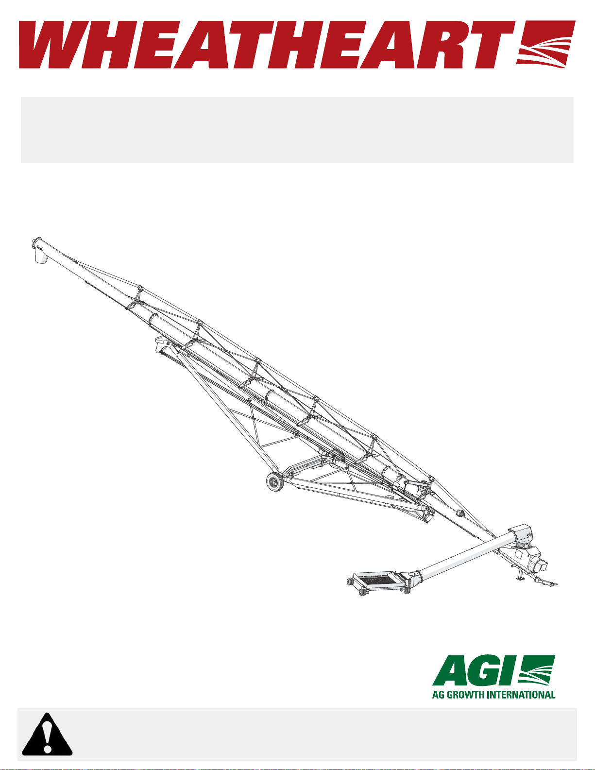
GRAIN AUGERS
X160-85/105/125
ASSEMBLY & OPERATION

This product has been designed and constructed according to general engineering
standardsa. Other local regulations may apply and must be followed by the operator.
We strongly recommend that all personnel associated with this equipment be trained
in the correct operational and safety procedures required for this product. Periodic
reviews of this manual with all employees should be standard practice. For your
convenience, we include this sign-off sheet so you can record your periodic reviews.
Date Employee Signature Employer Signature
a. Standards include organizations such as the American Society of Agricultural and Biological Engineers,
American National Standards Institute, Canadian Standards Association, International Organization for
Standardization, EN Standards, and/or others.

HEATHEART GRAIN AUGERS
W
X160-85, X160-105, X160-125
TABLE OF CONTENTS
1. Introduction .......................................................................................................................... 7
1.1. Overview .................................................................................................................. 8
1.1.1. Grain Transfer Boot and PTO Driveline...................................................... 9
1.1.2. Grain Hopper ............................................................................................ 10
1.1.3. Auger Tube Hydraulic Lift ......................................................................... 12
2. Safety .................................................................................................................................. 13
2.1. General Safety Information .................................................................................... 13
2.2. Assembly Safety..................................................................................................... 14
2.3. Operation Safety .................................................................................................... 15
2.4. PTO Safety............................................................................................................. 17
2.5. Hydraulic Safety ..................................................................................................... 17
2.6. Transport & Placement Safety ............................................................................... 18
2.7. Maintenance Safety................................................................................................ 18
2.8. Safety Decals ......................................................................................................... 19
2.8.1. Decal Installation/Replacement ................................................................ 19
2.8.2. Safety Decal Locations............................................................................. 19
2.8.3. Safety Decal Detail ................................................................................... 26
3. Assembly ............................................................................................................................ 35
3.1. General Assembly .................................................................................................. 35
3.2. Assemble the Auger Tube...................................................................................... 37
3.2.1. Identify and Arrange Auger Tube Sections............................................... 37
3.2.2. Connect Auger Tubes ............................................................................. 40
3.2.3. Install the Hydraulic Lift Cylinders ............................................................ 42
3.2.4. Install the Track Shoe and Track Stop ..................................................... 46
3.2.5. Install the Boot on the Auger Tube ........................................................... 47
3.2.6. Assemble the PTO Shield Assembly........................................................ 49
3.2.7. Install the Speed Reducer on the Boot..................................................... 50
3.2.8. Install the Boot Tow Bar ........................................................................... 53
3.2.9. Install the Discharge Spout....................................................................... 54
3.2.10. Set the Thrust Adjuster........................................................................... 55
3.2.11. Apply Logo and Model Decals on the Auger Tubes ............................... 56
3.3. Install Truss Support Towers and Truss Tubes...................................................... 58
3.4. Install Truss Cables................................................................................................
66
3.5. Assemble the Lower Frame ................................................................................... 68
3.6. Assemble the Wheel Hub and Install Tires ............................................................ 70
30875 R0 3

W
X160-85, X160-105, X160-125
TABLE OF CONTENTS
3.7. Connect the Auger Tube to the Frame ................................................................... 71
3.8. Install Lift Cylinder Cables to the Track shoe ........................................................ 74
3.9. Connect Hydraulic Hoses and Ball Valve ............................................................... 76
3.10. Connect the PTO Driveline................................................................................... 82
3.11. Connect the Intake Hopper to the Swing Tube..................................................... 83
3.12. Connect the Spout Head to the Grain Transfer Boot............................................ 87
3.13. Install the Hopper Lift Arm .................................................................................... 89
3.14. Install the Hydraulic Winch ................................................................................... 90
3.15. Power Swing Assembly ........................................................................................ 93
3.15.1. Connect the Lower Clamp to the Power Swing ...................................... 94
3.15.2. Connect the Wheels on the Power Swing .............................................. 94
3.15.3. Connect the Power Swing Wheel Assembly to the Tube ....................... 95
3.15.4. Connecting the Power Swing Wiring ...................................................... 96
3.16. Install the Hitch Jack ............................................................................................ 99
3.17. Install the Manual Container............................................................................... 100
3.18. Auger-to-Tractor Hookup.................................................................................... 101
HEATHEART GRAIN AUGERS
4. Transport........................................................................................................................... 103
4.1. Transport Position ................................................................................................ 103
5. Placement ......................................................................................................................... 107
5.1. Placement Procedure ........................................................................................... 107
6. Operation .......................................................................................................................... 113
6.1. Operator Controls ................................................................................................. 113
6.2. Pre-Operation ....................................................................................................... 115
6.2.1. Checklist ................................................................................................. 115
6.2.2. PTO Drive ............................................................................................... 116
6.2.3. Hydraulics ............................................................................................... 116
6.2.4. Electric Power Swing Operation ............................................................. 117
6.3. Operating Procedures .......................................................................................... 118
6.3.1. Initial Start-Up ......................................................................................... 119
6.3.2. Normal Start............................................................................................ 120
6.3.3. Normal Shutdown ................................................................................... 121
6.3.4. Emergency Stop / Full-Tube Restart ...................................................... 122
6.3.5. Lowering & Completion........................................................................... 122
6.3.6. Operation in Reverse.............................................................................. 123
4 30875 R0

HEATHEART GRAIN AUGERS
W
X160-85, X160-105, X160-125
7. Maintenance and Storage................................................................................................ 125
7.1. Maintenance Intervals .......................................................................................... 125
7.2. Fluids and Lubricants ........................................................................................... 126
7.3. Maintenance Procedures ..................................................................................... 126
7.3.1. Visual Inspection .................................................................................... 126
7.3.2. Hydraulic Hose and Coupler Inspection ................................................. 127
7.3.3. Machine Greasing .................................................................................. 127
7.3.4. Hopper Lift Cable Inspection .................................................................. 129
7.3.5. Winch and Pulley Servicing .................................................................... 130
7.3.6. Gearbox Coupling Shaft Servicing ......................................................... 130
7.3.7. Hopper Chain Drive Servicing ................................................................ 131
7.3.8. Gearbox Oil Level................................................................................... 132
7.3.9. Machine Cleaning................................................................................... 132
7.3.10. Tire Pressure Check............................................................................. 132
7.3.11. Wheel Bearings Repack ....................................................................... 132
7.3.12. Wheel Bolt Tightening .......................................................................... 133
7.3.13. Truss Cable Adjustment ....................................................................... 133
7.3.14. Changing Gearbox Oil .......................................................................... 134
7.4. Storage................................................................................................................. 134
7.5. Power Swing ........................................................................................................ 135
7.5.1. Power Swing Maintenance ..................................................................... 135
7.5.2. Power Swing Storage ............................................................................ 135
8. T roubleshooting............................................................................................................... 137
9. Appendix........................................................................................................................... 139
9.1. Specifications ....................................................................................................... 139
9.2. Bolt Torque Values............................................................................................... 140
9.3. Remote Transmitter Instructions .......................................................................... 142
Warranty................................................................................................................................ 145
30875 R0 5

W
X160-85, X160-105, X160-125
HEATHEART GRAIN AUGERS
6 30875 R0

WHEATHEART - GRAIN AUGERS 1. INTRODUCTION
X160-85, X160-105, X160-125
1.Introduction
Thank you for purchasing a Wheatheart grain auger. Before using, please read
this manual and understand the various features of the equipment and precautions for efficient and safe operation.
Keep this manual handy for frequent reference and to review with new
personnel. A sign-off form is supplied on the inside front cover to record your
safety reviews. Call your local distributor or dealer if you need assistance or
additional information.
This manual should be regarded as part of the equipment. Suppliers of both new
and second-hand equipment are advised to retain documentary evidence that
this manual was provided with the machine.
Serial Number:
*Serial number is located on the lower tube.
30875 R0 7
1. INTRODUCTION WHEATHEART - GRAIN AUGERS
X160-85, X160-105, X160-125
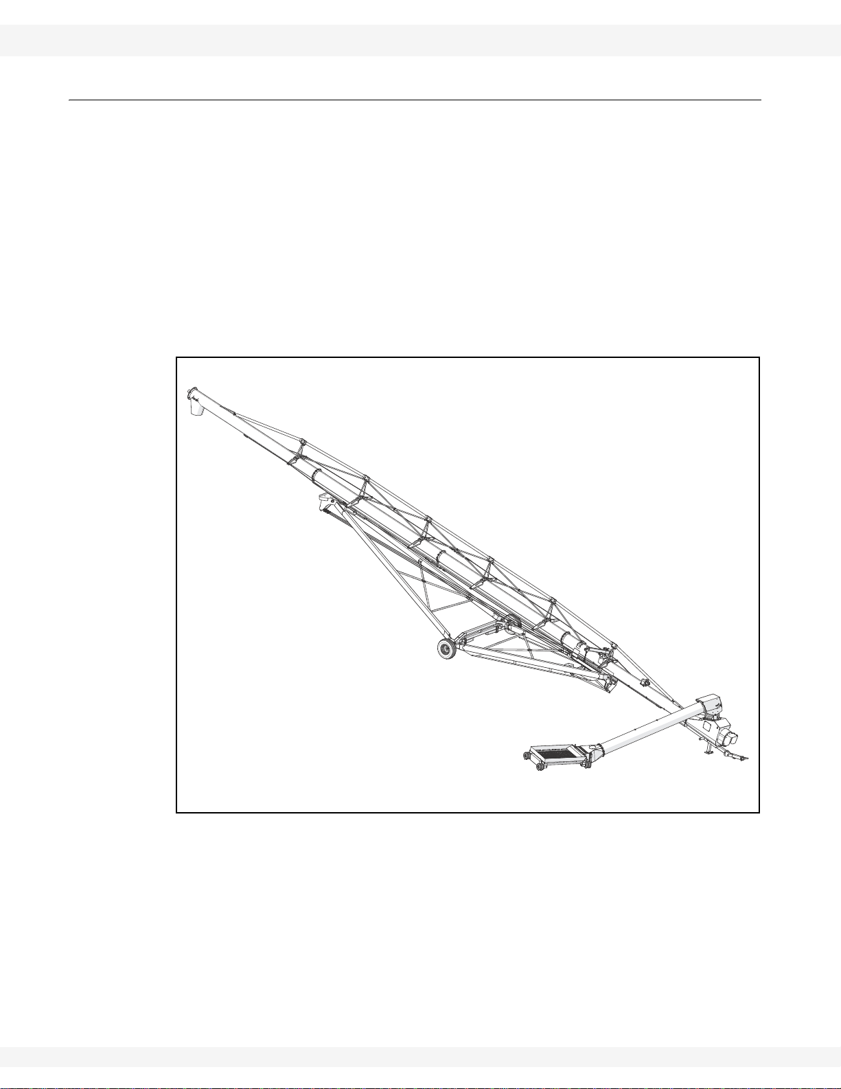
1.1. OVERVIEW
X160 augers are equipped with the following standard features:
• a high-capacity grain transfer boot
• a PTO driveline for auger power.
• a hydraulically controlled main auger tube lift
• a low-profile grain hopper (left or right side operation)
• a hydraulic winch for lifting the intake hopper
• an electric power swing for intake hopper
• a 1000 RPM PTO Drive (with forward and reverse auger direction capability)
Figure 1.1 X160 Series Auger (85’ model shown)
8 30875 R0
WHEATHEART - GRAIN AUGERS 1. INTRODUCTION
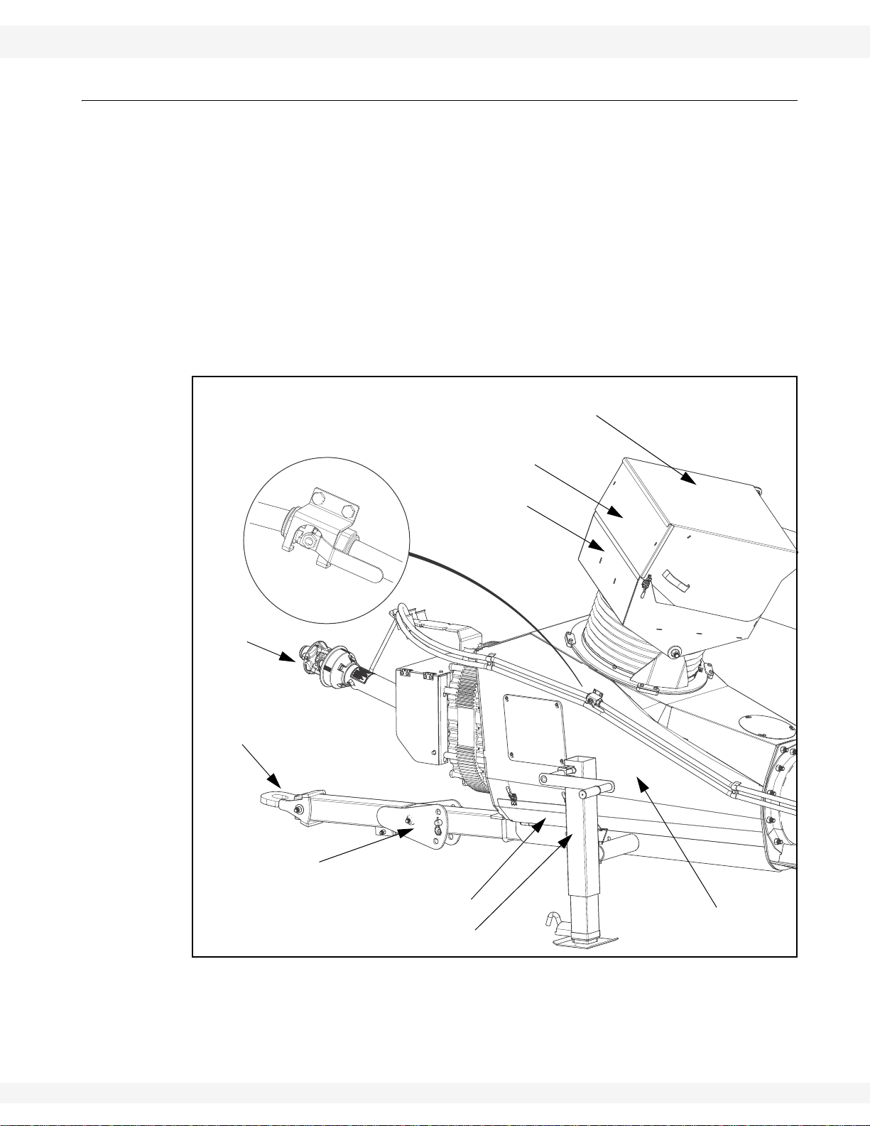
SPOUT HEAD
SPOUT HEAD SERVICE COVER
PTO DRIVELINE
HITCH
CLEAN-OUT HATCH
GRAIN TRANSFER BOOT
JACK
AUGER TUBE
LIFT VALVE
SPOUT HEAD
OVERFLOW PANEL
HITCH ANGLE
ADJUSTER
X160-85, X160-105, X160-125
1.1.1. GRAIN TRANSFER BOOT AND PTO DRIVELINE
The grain transfer boot is located at the bottom of the main auger tube, and
contains gearing for power transfer as well as flights for transferring grain.
The power source for the auger is a standard 1000 RPM tractor PTO. The PTO
driveline connections (both forward and reverse directions) are located on the
speed reducer gearbox above the tractor hitch.
The auger tube lift valve used to allow or shut off hydraulic pressure to the main
auger tube lift cylinders, and is located on the side of the boot (see figure below).
See section 6.1. for further information on auger controls.
Several access hatches are provided for maintenance and repair, as well as an
overflow panel on the swing-arm spout head and a clean-out hatch at the bottom
of the boot.
Figure 1.2 Grain Transfer Boot Features
30875 R0 9
1. INTRODUCTION WHEATHEART - GRAIN AUGERS
X160-85, X160-105, X160-125
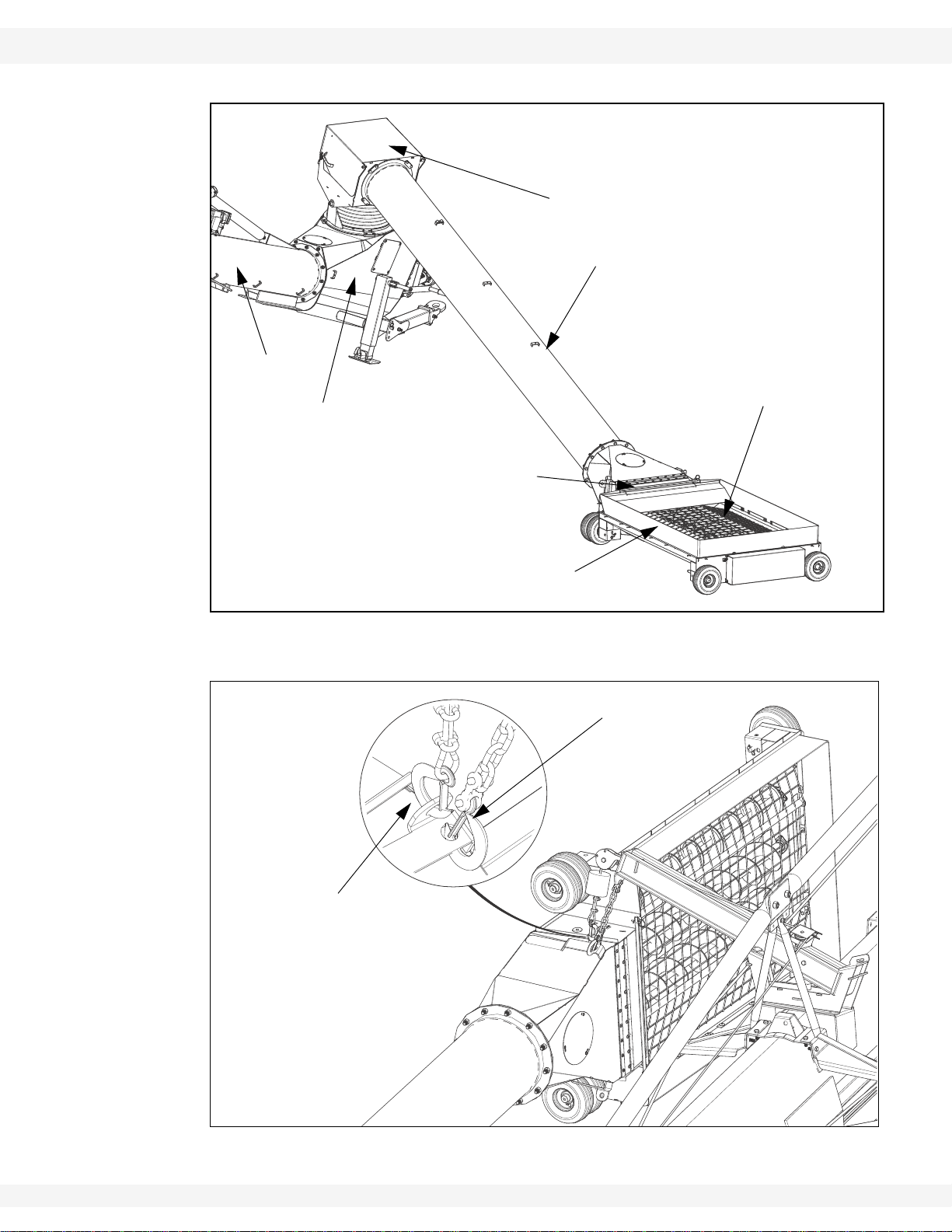
1.1.2. GRAIN HOPPER
The low-profile grain hopper is designed to be rolled into position to receive grain
for transfer through the boot to the auger discharge spout. Ground clearance can
be adjusted by raising or lowering the position of the hopper wheel axles (see
“Connect the Intake Hopper to the Swing Tube” on page 83).
The grain hopper must be lifted and secured for transport using the hopper lift
arm, hydraulic winch, and transport chain and hook (see Figure 1.4).The hopper
lift arm can be reconfigured for lifting on either side of the auger.
Do not approach, open or close the maintenance hatch located on the transition
between the swing are tube and the hopper unless all power to the auger is
locked out.
DANGER
Rotating Auger Hazard
Contact with rotating flighting will result in
amputation or severe laceration.
DO NOT operate with guards removed or
modified.
Keep hands and feet away from rotating
auger.
Tie up long hair and remove jewellery.
DO NOT wear loose-fitting clothing or items
that could become caught.
Shut off and lock out the power source before
unplugging or cleaning.
10 30875 R0
WHEATHEART - GRAIN AUGERS 1. INTRODUCTION
CLEANOUT HATCH
FLIGHTS AND FLIGHT GUARDING
INTAKE HOPPER
SWING ARM
SPOUT HEAD
BOOT
MAIN AUGER
TUBE
SAFETY CHAIN
AND HOOK
WINCH CHAIN
AND HOOK
X160-85, X160-105, X160-125
Figure 1.3 Grain Hopper
Figure 1.4 Grain Hopper Lifted into Transport Position
30875 R0 11
1. INTRODUCTION WHEATHEART - GRAIN AUGERS
X160-85, X160-105, X160-125
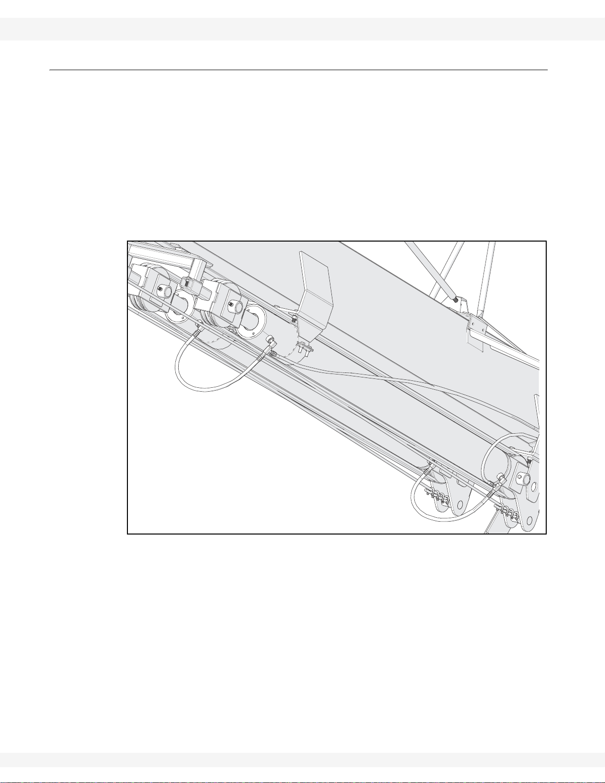
1.1.3. AUGER TUBE HYDRAULIC LIFT
The auger tube is raised and lowered using single-acting hydraulic cylinders
powered by the hydraulic supply of the connected tractor. The main auger tube is
raised by extending the cylinders, and lowered by allowing the cylinders to
retract. (see Figure 1.5).
A hydraulic ball valve mounted on the side of the grain pick-up boot controls flow
of hydraulic fluid to the lift cylinders, and with appropriate use of the hydraulic
controls on the connected tractor, allows the main auger tube to be raised,
lowered, or locked at a specific height during operation (see “Operator Controls”
on page 113).
Figure 1.5 Auger Tube Hydraulic Lift Cylinders
12 30875 R0
WHEATHEART - GRAIN AUGERS 2. SAFETY
X160-85, X160-105, X160-125
2.Safety
2.1. GENERAL SAFETY INFORMATION
The Safety Alert symbol identifies important safety messages on the product and
in the manual. When you see this symbol, be alert to the possibility of personal
injury or death. Follow the instructions in the safety messages.
Why is SAFETY important?
• Accidents disable and kill.
• Accidents cost.
• Accidents can be avoided.
SIGNAL WORDS: Note the use of the signal words DANGER, WARNING,
CAUTION, and NOTICE with the safety messages. The appropriate signal word
for each message has been selected using the definitions below as a guideline.
DANGER
Indicates an imminently hazardous situation
that, if not avoided, will result in serious injury
or death.
WARNING
Indicates a hazardous situation that, if not
avoided, could result in serious injury or
death.
CAUTION
Indicates a hazardous situation that, if not
avoided, may result in minor or moderate
injury.
NOTICE
Indicates a potentially hazardous situation that, if not
avoided, may result in property damage.
30875 R0 13

2. SAFETY WHEATHEART - GRAIN AUGERS
X160-85, X160-105, X160-125
YOU are responsible for the SAFE use and maintenance of your equipment.
YOU must ensure that you and anyone else who is going to work around the
equipment understands all procedures and related SAFETY information
contained in this manual.
Remember, YOU are the key to safety. Good safety practices not only protect
you, but also the people around you. Make these practices a working part of your
safety program.
Important: Below are general instructions that apply to all safety practices. Any instructions
specific to a certain safety practice (e.g., Operational Safety), can be found in the
appropriate section. Always read the complete instructional sections and not just
these safety summaries before doing anything with the equipment.
• It is the equipment owner, operator, and maintenance personnel's responsi-
bility to read and understand ALL safety instructions, safety decals, and man-
uals and follow them when assembling, operating, or maintaining the
equipment. All accidents can be avoided.
• Equipment owners must give instructions and review the information initially
and annually with all personnel before allowing them to operate this product.
Untrained users/operators expose themselves and bystanders to possible
serious injury or death.
• Use this equipment for its intended purposes only.
• Do not modify the equipment in any way without written permission from the
manufacturer. Unauthorized modification may impair the function and/or
safety, and could affect the life of the equipment. Any unauthorized modification of the equipment voids the warranty.
• Do not allow any unauthorized person in the work area.
2.2. ASSEMBLY SAFETY
• Read and understand the instructions to get to know the sub-assemblies and
hardware that make up the equipment before preceding to assemble the
product.
• Do not take chances with safety. The components are large, heavy, and can
be hard to handle. Always use the proper tools, stands, jacks, and hoists for
the job.
• Read and understand assembly instructions before proceeding to assemble
the product.
• Always have two or more people assembling the equipment. Because of the
weight, do not attempt assembly alone.
14 30875 R0

WHEATHEART - GRAIN AUGERS 2. SAFETY
X160-85, X160-105, X160-125
2.3. OPERATION SAFETY
• Have another trained person nearby who can shut down the auger in case of
accident. Always work with a second trained person around augers.
• Do not operate with any of the safety guards removed.
• Keep body, hair, and clothing away from moving parts. Stay away from intake
during operation.
• Inspect lift cable before using auger. Replace if frayed or damaged. Make
sure it is seated properly in cable sheaves and cable clamps are secure.
• Operate auger on level ground free of debris. If ground is uneven, anchor the
auger to prevent tipping or upending.
• Augers are not insulated. Keep away from electrical lines. Electrocution can
occur without direct contact.
• Support the discharge end and/or anchor the intake end before operating to
prevent upending.
• Do not use auger as a hoist.
• Empty auger before raising or lowering.
• Lower auger at completion of operation or when not in use. Auger could drop
rapidly in case of cable break or hydraulic failure (where applicable).
• Keep the work area clean and tidy.
• Do not get on or beneath auger when raising or lowering intake hitch jack, or
when auger is supported by hitch jack.
• Do not operate auger with the service or clean-out doors open or unlatched.
30875 R0 15
2. SAFETY WHEATHEART - GRAIN AUGERS
BIN
X160-85, X160-105, X160-125
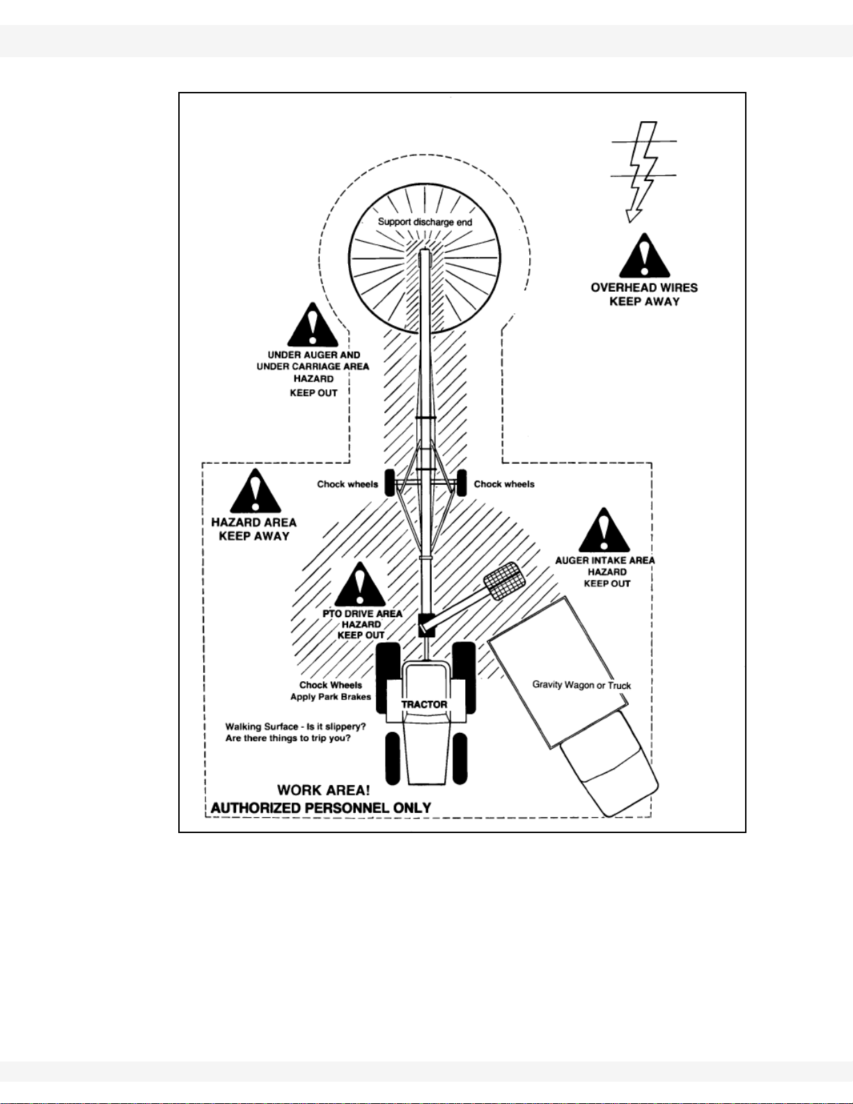
Figure 2.1 Operational Safety, Work Areas
16 30875 R0

WHEATHEART - GRAIN AUGERS 2. SAFETY
X160-85, X160-105, X160-125
2.4. PTO SAFETY
• Never use a PTO driveline without a rotating shield in good working order.
• Ensure PTO driveline is securely attached at both ends before operating.
• Before starting tractor, turn power to PTO to the off position (where applicable).
• Keep body, hair, and clothing away from rotating PTO driveline.
• Ensure the PTO driveline shields turn freely on the PTO driveline.
• Do not exceed PTO operating speed of 1000 rpm.
• Keep u-joint angles small and equal. Do not exceed recommended operating
length for PTO driveline.
2.5. HYDRAULIC SAFETY
• Wear proper hand and face protection when searching for hydraulic leaks.
Escaping fluid under pressure can penetrate the skin, causing serious injury
like gangrene. In case of accident, see a doctor immediately.
• Fluid leaks in the hydraulic lift cylinders or hoses will allow the auger to lower
inadvertently. Repair all leaks and breaks immediately. Rupture could cause
damage and/or personal injury.
• A hydraulic lift is faster than a conventional hand crank—always clear area of
personnel before raising or lowering.
• Do not disconnect hydraulic couplers when hydraulic system is pressurized.
For the correct procedure, consult this manual or your tractor manual.
• Relieve pressure before unhooking hydraulic lines.
• Inspect hydraulic fittings and hoses for damage on a daily basis. Repair if
damaged.
• Ensure that the hydraulic line(s) is (are) properly connected and secure.
• Keep hydraulic line(s) away from moving parts.
• Clean connections before connecting to equipment.
30875 R0 17
2. SAFETY WHEATHEART - GRAIN AUGERS
X160-85, X160-105, X160-125
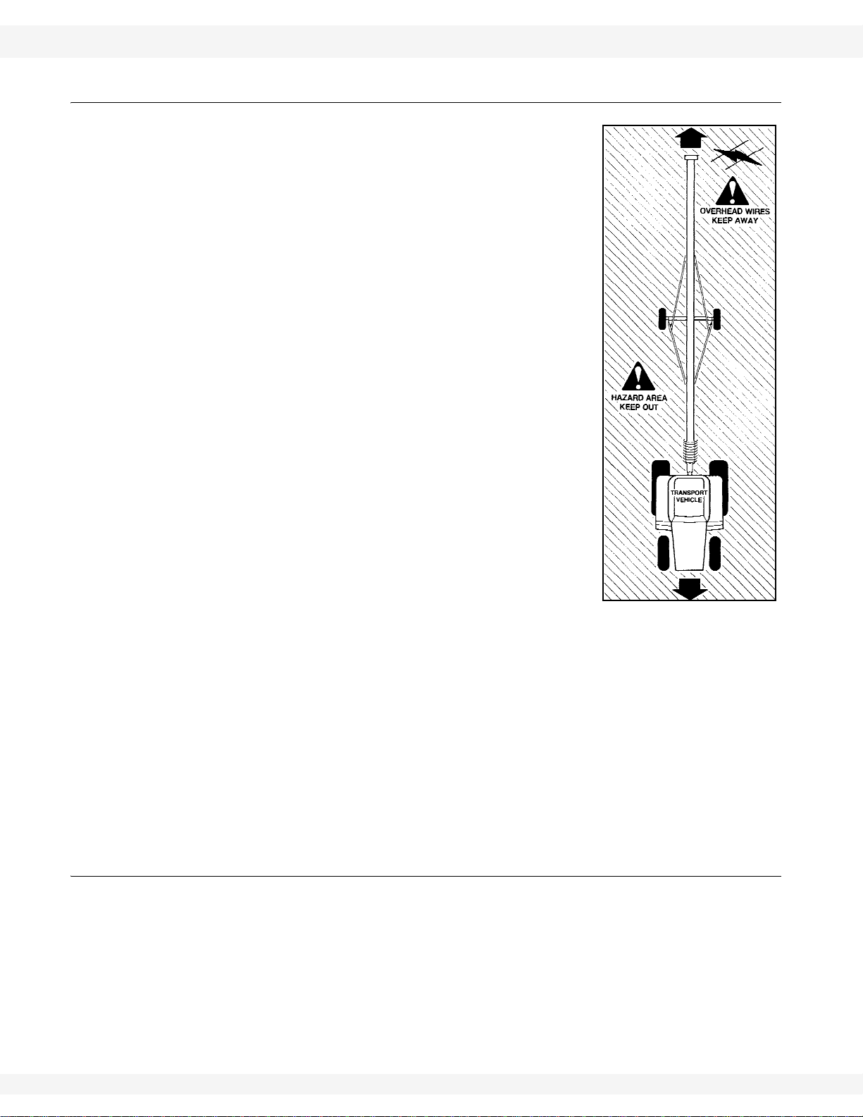
2.6. TRANSPORT & PLACEMENT SAFETY
• Transport auger in full down position with slight tension on cable.
• Properly place hitch pin and securely attach safety
chain. Use a type of hitch pin that will not allow
auger to separate from towing vehicle.
• Always attach an SMV (slow moving vehicle) sign
before transporting auger. Equip the auger with the
necessary lights for transportation where required
by law. Always use hazard warning flashers on the
tractor/towing vehicle when transporting unless
prohibited by law.
• Always travel at a safe speed, never exceeding 15
mph (24 km/hr). Reduce speed on rough surfaces
and be cautious when turning corners or meeting
traffic.
• Before raising/lowering/moving the auger, make
sure the area around the auger is clear of obstructions and/or untrained personnel. Never allow anyone to stand on or beneath auger while
transporting or placing auger.
• Do not transport auger on slopes greater than 20°.
• Wheels must be free to move when raising or lowering auger.
• Never attempt to move auger manually. To do so
will result in serious injury.
• Before moving auger, check and double check for overhead obstructions and/
or electrical wires. Electrocution can occur without direct contact.
• Disconnect PTO driveline from tractor before moving auger or tractor and
secure in transport saddle (where applicable).
• Raise intake feed hopper into transport position and lock hopper lift winch
before transporting or moving auger. Intake feed side of hopper must face
main auger when in transport position.
• Do not operate auger with intake hopper in transport position. This will cause
damage to the u-joint.
2.7. MAINTENANCE SAFETY
• Shut down and lock out all power before attempting maintenance of any kind.
Turn off the tractor and disconnect the PTO driveline and hydraulic hoses
from the tractor.
• After maintenance is complete, replace and secure all safety guards and
safety devices, and if applicable, service doors and cleanout covers.
• Support auger tube before attempting maintenance on the undercarriage
assembly. Auger should be in full down position for maintenance.
18 30875 R0

WHEATHEART - GRAIN AUGERS 2. SAFETY
X160-85, X160-105, X160-125
• Use only genuine Wheatheart replacement parts or equivalent. Replacement
parts such as intake guards, pulley guards, PTO driveline shields, winches,
and lift cables must meet ASABE standards or serious injury may result. Use
of unauthorized parts will void warranty. If in doubt, contact Wheatheart or
your Wheatheart dealer.
• Do not modify any auger components without authorization from Wheatheart.
Modification can be dangerous and result in serious injuries.
2.8. SAFETY DECALS
• Keep safety decals clean and legible at all times.
• Replace safety decals that are missing or have become illegible. See decal
location figures that follow.
• Replaced parts must display the same decal(s) as the original part.
• Replacement safety decals are available free of charge from your distributor,
dealer, or factory.
2.8.1. DECAL INSTALLATION/REPLACEMENT
1. Decal area must be clean and dry, with a temperature above 50°F (10°C).
2. Decide on the exact position before you remove the backing paper.
3. Align the decal over the specified area and carefully press the small portion
with the exposed sticky backing in place.
4. Slowly peel back the remaining paper and carefully smooth the remaining
portion of the decal in place.
5. Small air pockets can be pierced with a pin and smoothed out using the sign
backing paper.
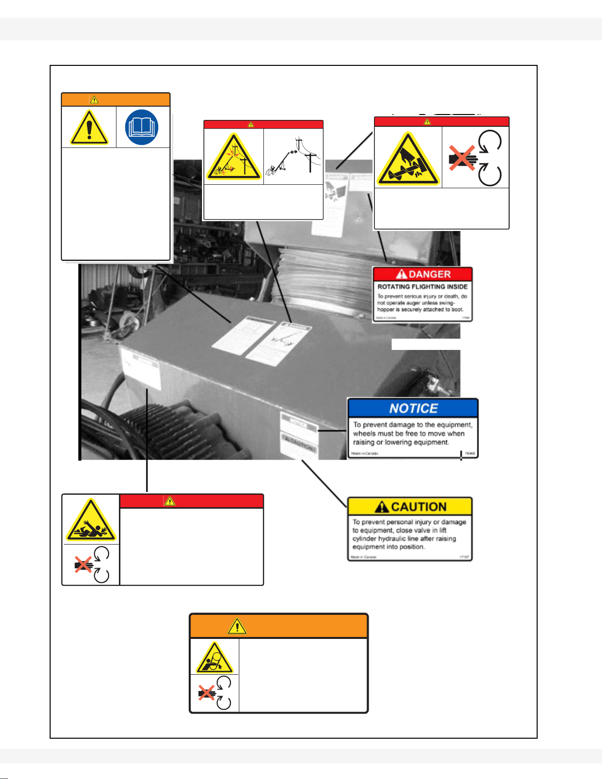
2.8.2. SAFETY DECAL LOCATIONS
Replicas of the safety decals that are attached to the equipment and their
messages are shown in the figure(s) that follow. Safe operation of the equipment
requires that you familiarize yourself with the various safety decals and the areas
or particular functions that the decals apply to, as well as the safety precautions
that must be taken to avoid serious injury, death, or damage.
Please review the decals shown. If your auger does not have these decals, they
are available upon request. Please specify which decals you need.
30875 R0 19

2. SAFETY WHEATHEART - GRAIN AUGERS
X160-85, X160-105, X160-125
Table 2.1. Safety Decal Description, Detail, and Location Information
Number Description Detail Location
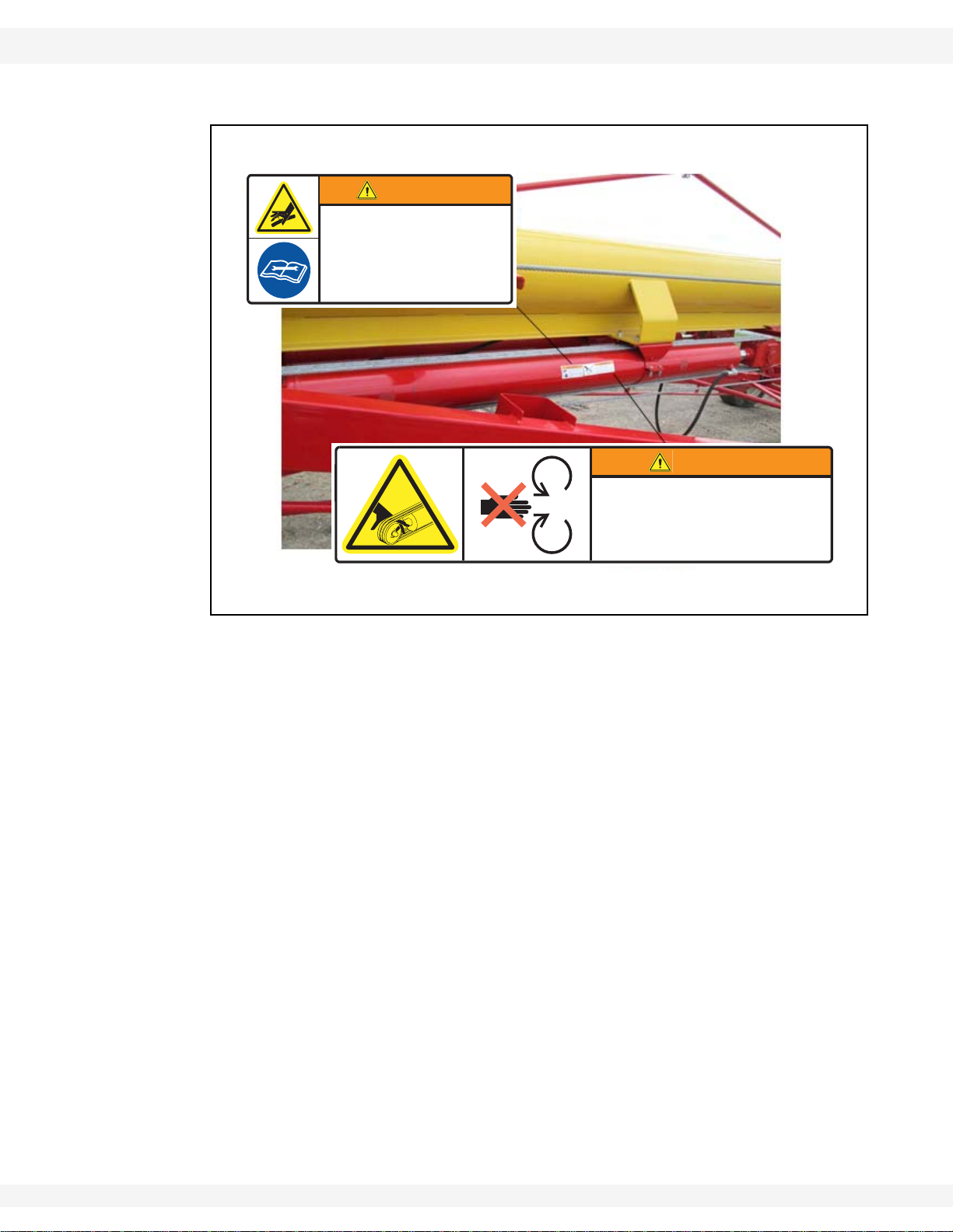
20806 High pressure fluid hazard (Warning) Figure 2.7 Figure 2.2
20809 Rotating cable sheaves hazard (Warning) Figure 2.8 Figure 2.2
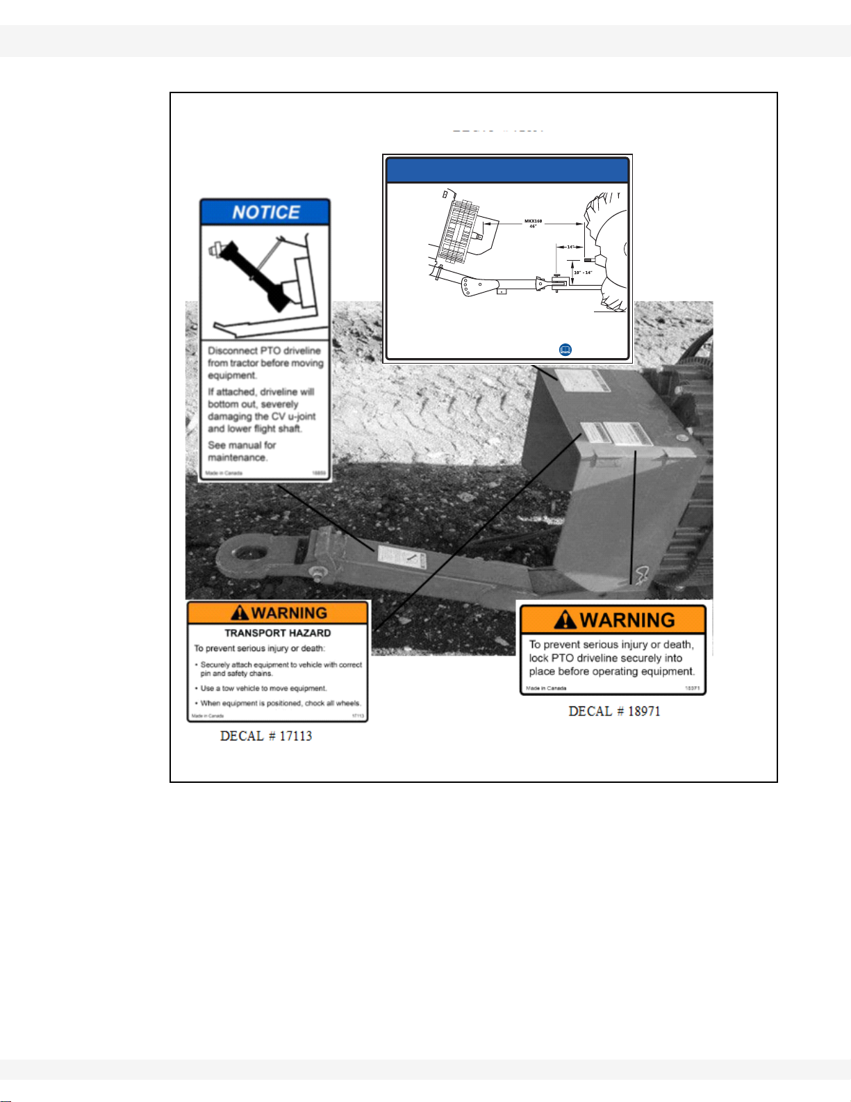
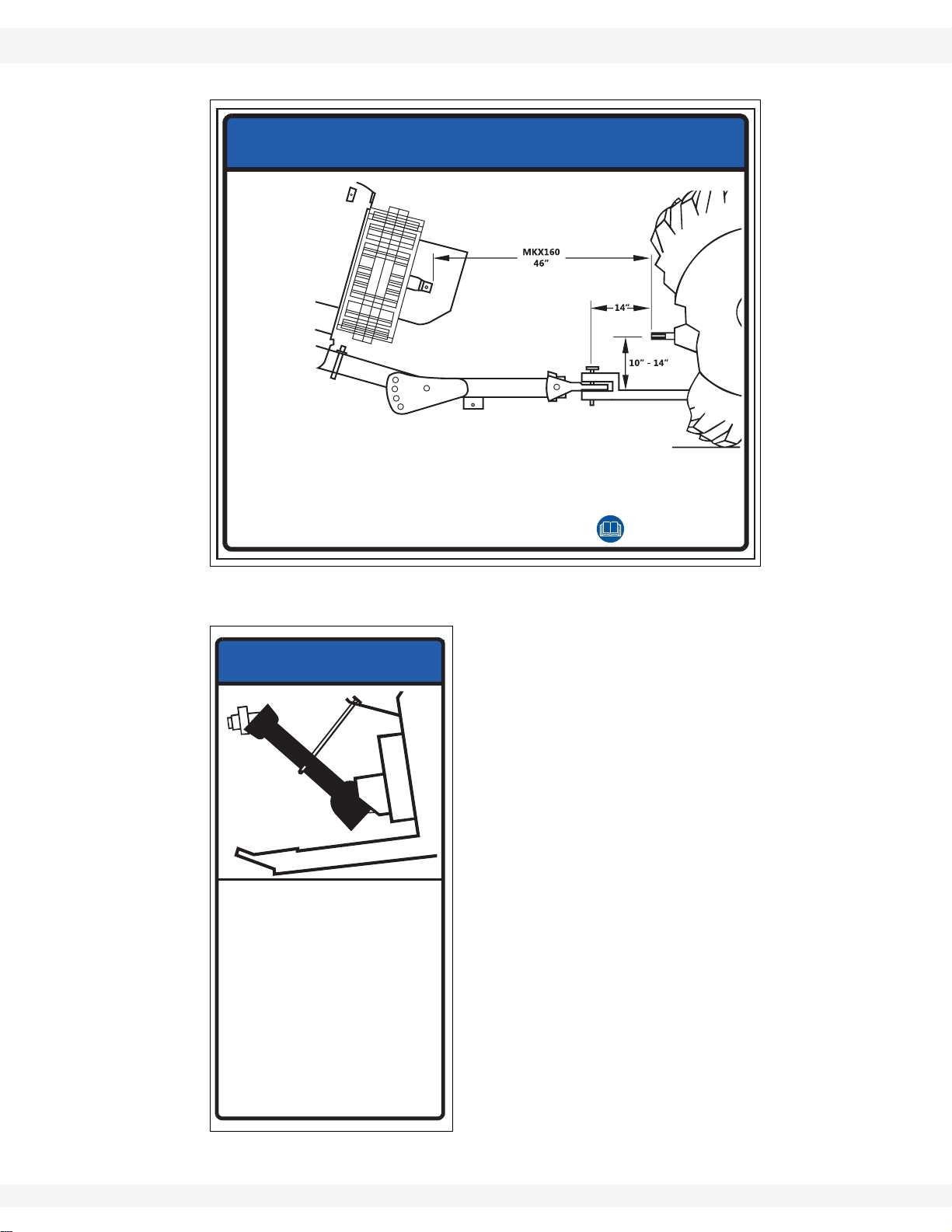
21074 Auger-to-tractor hookup (Notice) Figure 2.9
Figure 2.3
Figure 2.5
18859 Disconnect PTO driveline (Notice) Figure 2.10 Figure 2.3
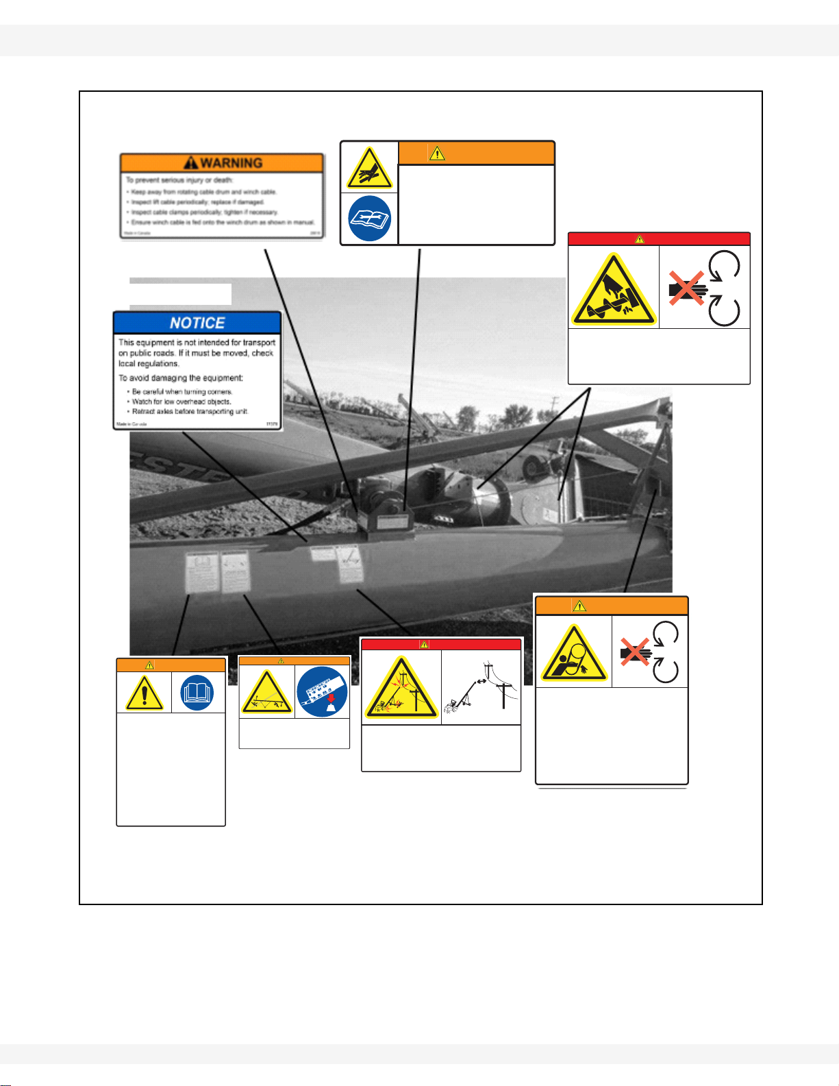
17378 Transport restrictions (Notice) Figure 2.11 Figure 2.3
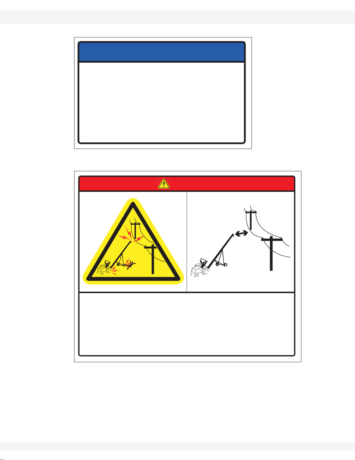
20816 Electrocution hazard (Danger) Figure 2.12
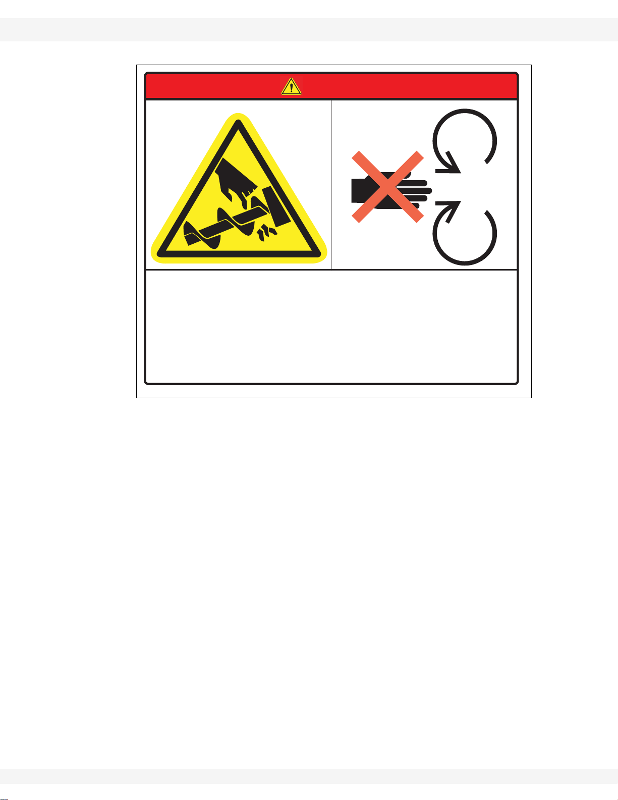
20813 Rotating flighting hazard (Danger) Figure 2.13
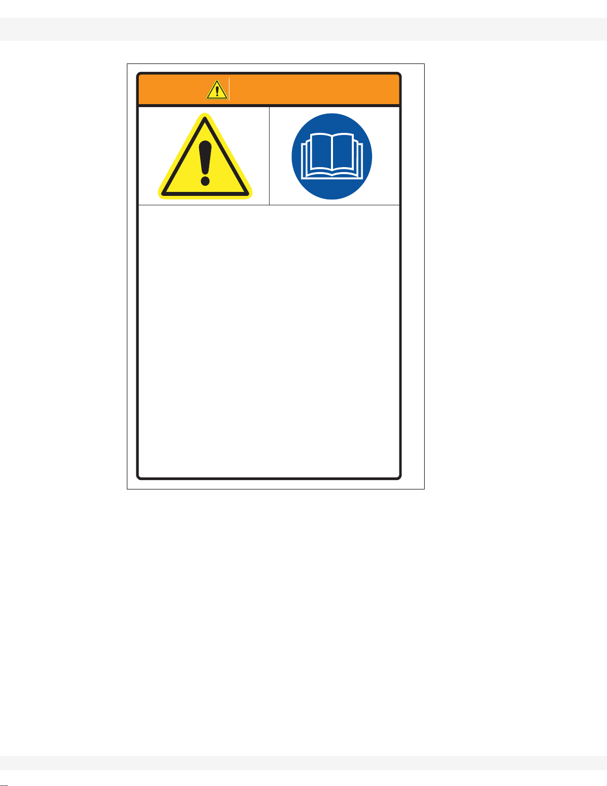
20807 Serious injury or death hazards (Warning) Figure 2.14
Figure 2.4
Figure 2.5
Figure 2.4
Figure 2.5
Figure 2.4
Figure 2.5
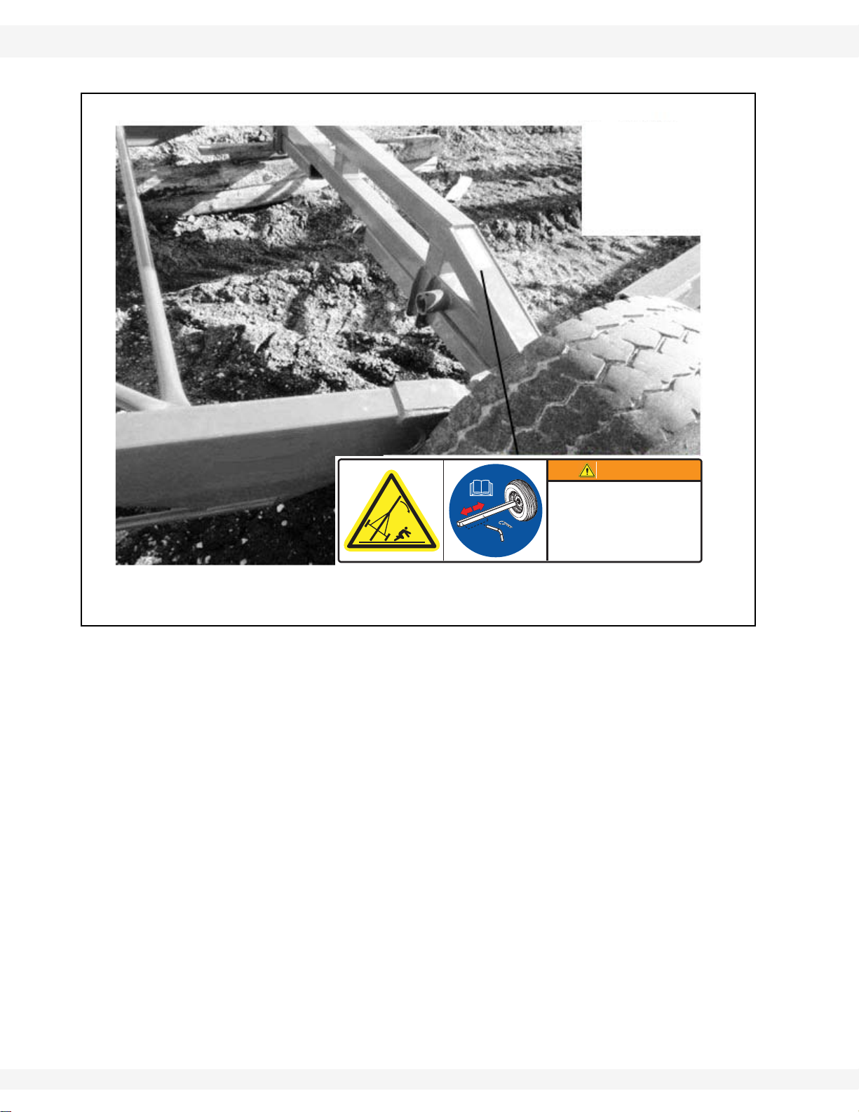
20811 Upending hazard (Warning) Figure 2.15 Figure 2.4
20804 Transport hazard, hitching and towing (Warning) Figure 2.16
17101 Entanglement hazard (Warning) Figure 2.17
Figure 2.4
Figure 2.5
Figure 2.4
Figure 2.5
17107 Close lift valve after raising (Caution) Figure 2.18 Figure 2.5
17094 Rotating flighting, grain transfer boot (Danger) Figure 2.19 Figure 2.5
19960 Chocking/unchocking wheels (Notice) Figure 2.20 Figure 2.5
20818 Rotating PTO driveline hazard (Danger) Figure 2.21 Figure 2.5
20803 Reattach missing guards (Warning) Figure 2.22 Figure 2.5
20812 Rollover/transport hazard (Warning) Figure 2.23 Figure 2.6
* Wheatheart reserves the right to update safety decals without notice. Safety
decals may not be exactly as shown.
20 30875 R0
WHEATHEART - GRAIN AUGERS 2. SAFETY
WARNING
To prevent serious injury or death:
• Keep away from rotating cable sheaves and lift
cables.
• Inspect lift cable periodically; replace if damaged.
• Inspect cable clamps periodically; tighten if
necessary.
20809
Made in Canada
DECAL #20809
DECAL #20806
X160-85, X160-105, X160-125
Figure 2.2 Hydraulic Safety Decal Locations
WARNING
HIGH PRESSURE FLUID HAZARD
Hydraulic fluid can cause serious injury if it
penetrates the skin. If it does, see a doctor
immediately.
• Relieve pressure before unhooking hydraulic line.
• Wear proper hand and eye protection, and use wood
or cardboard, not hands, when searching for leaks.
60802adanaC ni edaM
30875 R0 21
2. SAFETY WHEATHEART - GRAIN AUGERS
• Follow dimensions above for correct
auger-to-tractor hookup.
To prevent
damage
during
auger-totractor
hookup:
• Adjust drawbar as needed.
• See operation manual for complete details.
• Auger must be on level ground and in full down
position when measuring.
21074
Made in Canada
DECAL #21074
DECAL #18859
X160-85, X160-105, X160-125
Figure 2.3 PTO and Towbar Safety Decal Locations
NOTICE
22 30875 R0
WHEATHEART - GRAIN AUGERS 2. SAFETY
WARNING
HIGH PRESSURE FLUID HAZARD
Hydraulic fluid can cause serious injury if it
penetrates the skin. If it does, see a doctor
immediately.
• Relieve pressure before unhooking hydraulic line.
• Wear proper hand and eye protection, and use wood
or cardboard, not hands, when searching for leaks.
60802adanaC ni edaM
DECAL #20806
DECAL # 17378
DECAL #20811
WARNING
UPENDING HAZARD
To prevent death or serious injury:
• Anchor intake end and/or support
discharge end to prevent upending.
• Auger intake end must always have
downward weight. Do not release until
attached to tow bar or resting on ground.
• Do not raise auger intake end above tow
bar height.
• Empty auger and fully lower before
moving.
20811
Made in Canada
DECAL #20811
DECAL #20807
WARNING
To prevent serious injury or death:
• Read and understand the manual before
assembling, operating, or maintaining the
equipment.
• Only trained personnel may assemble, operate, or
maintain the equipment.
• Children and untrained personnel must be kept
outside of the work area.
• If the manual, guards, or decals are missing or
damaged, contact factory or dealer for replacements.
• Lock out power before performing maintenance.
• To prevent equipment collapse, support equipment
tube while disassembling certain components.
• Electric motors must be grounded. Disconnect power
before resetting overloads.
Made in Canada 20807
DANGER
ELECTROCUTION HAZARD
To prevent death or serious injury:
• When operating or moving, keep equipment away from overhead power lines and devices.
• Fully lower equipment and truck box before moving.
This equipment is not insulated.
Electrocution can occur without direct contact.
20816
Made in Canada
DECAL #20816
DECAL #20813
DECAL # 28616
PLACED ON HOPPER
CHAIN COVER
X160-85, X160-105, X160-125
Figure 2.4 Auger Tube and Hopper Safety Decal Locations
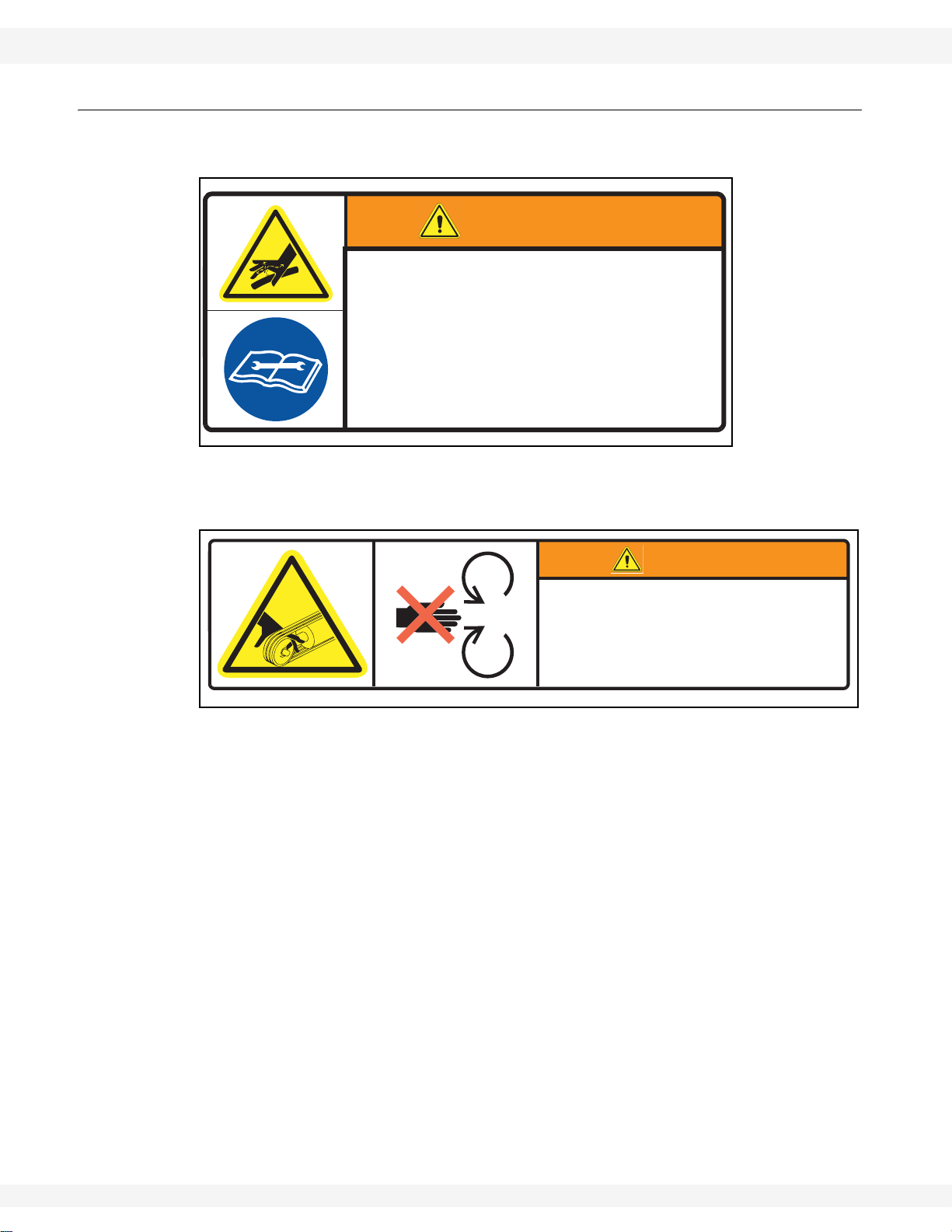
DANGER
ENTANGLEMENT HAZARD
To prevent serious injury or death:
• Keep body, hair, and clothing away from rotating
pulleys, belts, chains, and sprockets.
• Do not operate with any guard removed or
modified. Keep guards in good working order.
• Shut off and remove key or lock out power before
source before inspecting or servicing machine.
Made in Canada
To prevent death or serious injury:
• KEEP AWAY from rotating auger flighting.
• DO NOT remove or modify auger flighting
20813
Made in Canada
ROTATING FLIGHTING HAZARD
guards, doors, or covers. Keep in good
working order. Have replaced if damaged.
WARNING
• DO NOT operate the auger without all
guards, doors, and covers in place.
• NEVER touch the auger flighting. Use a
stick or other tool to remove an
obstruction or clean out.
• Shut off and lock out power to adjust,
service, or clean.
20804
30875 R0 23
2. SAFETY WHEATHEART - GRAIN AUGERS
PLACED BEHIND GUARDS
WARNING
MISSING GUARD HAZARD
To prevent serious injury or
death, shut off power and
reattach guard before operating
machine.
20803
Made in Canada
DECAL #20818
DANGER
ELECTROCUTION HAZARD
To prevent death or serious injury:
• When operating or moving, keep equipment away from overhead power lines and devices.
• Fully lower equipment and truck box before moving.
This equipment is not insulated.
Electrocution can occur without direct contact.
20816
Made in Canada
DECAL #20816
DANGER
ROTATING FLIGHTING HAZARD
To prevent death or serious injury:
• KEEP AWAY from rotating auger flighting.
• DO NOT remove or modify auger flighting
guards, doors, or covers. Keep in good
working order. Have replaced if damaged.
• DO NOT operate the auger without all
guards, doors, and covers in place.
• NEVER touch the auger flighting. Use a
stick or other tool to remove an
obstruction or clean out.
• Shut off and lock out power to adjust,
service, or clean.
20813
Made in Canada
DECAL #20813
WARNING
To prevent serious injury or death:
• Read and understand the manual before
assembling, operating, or maintaining the
equipment.
• Only trained personnel may assemble, operate, or
maintain the equipment.
• Children and untrained personnel must be kept
outside of the work area.
• If the manual, guards, or decals are missing or
damaged, contact factory or dealer for replacements.
• Lock out power before performing maintenance.
• To prevent equipment collapse, support equipment
tube while disassembling certain components.
• Electric motors must be grounded. Disconnect power
before resetting overloads.
Made in Canada 20807
DECAL #20807
DECAL #20803
DECAL #17107
DECAL #19960
DECAL #17904
Figure 2.5 Boot Safety Decal Locations
X160-85, X160-105, X160-125
24 30875 R0
DANGER
ROTATING PTO DRIVELINE HAZARD
To prevent serious injury or death:
• Keep body, hair, and clothing away from rotating PTO driveline.
• Do not operate equipment unless all driveline, tractor, and
equipment shields are in place and in good working order.
• Make certain the driveline shields turn freely on driveline.
• Make certain the driveline is securely attached at both ends.
• Do not exceed operating speed of 540 rpm.
• Keep u-joint angles small and equal. Do not exceed maximum
recommended length for PTO driveline.
Made in Canada 20818
WHEATHEART - GRAIN AUGERS 2. SAFETY
WARNING
ROLLOVER / TRANSPORT
HAZARD
To prevent serious injury or death:
• Fully extend axles before raising auger
tube.
• Retract axles before transporting.
20812
Made in
Canada
DECAL #20812
NOTE: TWO DECALS
ARE REQUIRED, ONE
ON EACH SIDE OF
THE AXLE
X160-85, X160-105, X160-125
Figure 2.6 Lower Frame Safety Decal Location
30875 R0 25
2. SAFETY WHEATHEART - GRAIN AUGERS
WARNING
HIGH PRESSURE FLUID HAZARD
Hydraulic fluid can cause serious injury if it
penetrates the skin. If it does, see a doctor
immediately.
• Relieve pressure before unhooking hydraulic line.
• Wear proper hand and eye protection, and use wood
or cardboard, not hands, when searching for leaks.
60802adanaC ni edaM
WARNING
To prevent serious injury or death:
• Keep away from rotating cable sheaves and lift
cables.
• Inspect lift cable periodically; replace if damaged.
• Inspect cable clamps periodically; tighten if
necessary.
20809
Made in Canada
X160-85, X160-105, X160-125
2.8.3. SAFETY DECAL DETAIL
Figure 2.7 Decal #20806
Figure 2.8 Decal #20809
26 30875 R0
WHEATHEART - GRAIN AUGERS 2. SAFETY
• Follow dimensions above for correct
auger-to-tractor hookup.
To prevent
damage
during
auger-totractor
hookup:
• Adjust drawbar as needed.
• See operation manual for complete details.
• Auger must be on level ground and in full down
position when measuring.
21074
Made in Canada
NOTICE
Disconnect PTO driveline
from tractor before moving
equipment.
If attached, driveline will
bottom out, severely
damaging the CV u-joint
and lower flight shaft.
See manual for
maintenance.
95881adanaC ni edaM
X160-85, X160-105, X160-125
NOTICE
Figure 2.9 Decal 21074
30875 R0 27
Figure 2.10 Decal 18859
2. SAFETY WHEATHEART - GRAIN AUGERS
NOTICE
This equipment is not intended for transport
on public roads. If it must be moved, check
local regulations.
To avoid damaging the equipment:
• Be careful when turning corners.
• Watch for low overhead objects.
• Retract axles before transporting unit.
17378
Made in
Canada
DANGER
ELECTROCUTION HAZARD
To prevent death or serious injury:
• When operating or moving, keep equipment away from overhead power lines and devices.
• Fully lower equipment and truck box before moving.
This equipment is not insulated.
Electrocution can occur without direct contact.
20816
Made in Canada
X160-85, X160-105, X160-125
Figure 2.11 Decal 17378
Figure 2.12 Decal 20816
28 30875 R0
WHEATHEART - GRAIN AUGERS 2. SAFETY
X160-85, X160-105, X160-125
DANGER
ROTATING FLIGHTING HAZARD
To prevent death or serious injury:
• KEEP AWAY from rotating auger flighting.
• DO NOT remove or modify auger flighting
guards, doors, or covers. Keep in good
working order. Have replaced if damaged.
20813
Made in Canada
Figure 2.13 Decal 20813
• DO NOT operate the auger without all
guards, doors, and covers in place.
• NEVER touch the auger flighting. Use a
stick or other tool to remove an
obstruction or clean out.
• Shut off and lock out power to adjust,
service, or clean.
30875 R0 29
2. SAFETY WHEATHEART - GRAIN AUGERS
X160-85, X160-105, X160-125
WARNING
To prevent serious injury or death:
• Read and understand the manual before
assembling, operating, or maintaining the
equipment.
• Only trained personnel may assemble, operate, or
maintain the equipment.
• Children and untrained personnel must be kept
outside of the work area.
• If the manual, guards, or decals are missing or
damaged, contact factory or dealer for replacements.
• Lock out power before performing maintenance.
• To prevent equipment collapse, support equipment
tube while disassembling certain components.
• Electric motors must be grounded. Disconnect power
before resetting overloads.
Made in Canada 20807
Figure 2.14 Decal 20807
30 30875 R0

WHEATHEART - GRAIN AUGERS 2. SAFETY
X160-85, X160-105, X160-125
WARNING
UPENDING HAZARD
To prevent death or serious injury:
• Anchor intake end and/or support
discharge end to prevent upending.
• Do not raise auger intake end above tow
bar height.
• Auger intake end must always have
downward weight. Do not release until
attached to tow bar or resting on ground.
• Empty auger and fully lower before
moving.
Figure 2.15 Decal 20811
WARNING
TRANSPORT HAZARD
To prevent serious injury or death:
• Securely attach equipment to vehicle with correct
pin and safety chains.
• Use a tow vehicle to move equipment.
20811
Made in Canada
31171adanaC ni edaM
Figure 2.16 Decal 17113
30875 R0 31

2. SAFETY WHEATHEART - GRAIN AUGERS
(LOCATED ON HOPPER
CHAIN GUARD)
X160-85, X160-105, X160-125
WARNING
ENTANGLEMENT HAZARD
To prevent serious injury or death:
• Keep body, hair, and clothing away from rotating
pulleys, belts, chains, and sprockets.
• Do not operate with any guard removed or
modified. Keep guards in good working order.
• Shut off and remove key or lock out power before
source before inspecting or servicing machine.
Made in Canada
20804
Figure 2.17 Decal 20804
CAUTION
To prevent personal injury or
damage to equipment, close valve in
lift cylinder hydraulic line after raising
equipment into position.
Figure 2.18 Decal 17107
Made in Canada
17107
32 30875 R0

WHEATHEART - GRAIN AUGERS 2. SAFETY
DANGER
ROTATING FLIGHTING INSIDE
To prevent serious injury or death, do
not operate auger unless swinghopper is securely attached to boot.
49071adanaC ni edaM
NOTICE
To prevent damage, wheels must be
free to move when raising or lowering
equipment.
When equipment is positioned, chock
all wheels.
Made in Canada 19960
DANGER
ROTATING PTO DRIVELINE HAZARD
To prevent serious injury or death:
• Keep body, hair, and clothing away from rotating PTO driveline.
• Do not operate equipment unless all driveline, tractor, and
equipment shields are in place and in good working order.
• Make certain the driveline shields turn freely on driveline.
• Make certain the driveline is securely attached at both ends.
• Do not exceed operating speed of 540 rpm.
• Keep u-joint angles small and equal. Do not exceed maximum
recommended length for PTO driveline.
Made in Canada 20818
X160-85, X160-105, X160-125
Figure 2.19 Decal 17094
Figure 2.20 Decal 19960
30875 R0 33
Figure 2.21 Decal 20818

2. SAFETY WHEATHEART - GRAIN AUGERS
PLACED ON MACHINE BEHIND GUARD
WARNING
ROLLOVER / TRANSPORT
HAZARD
To prevent serious injury or death:
• Fully extend axles before raising auger
tube.
• Retract axles before transporting.
20812
Made in
Canada
X160-85, X160-105, X160-125
WARNING
MISSING GUARD HAZARD
To prevent serious injury or
death, shut off power and
reattach guard before operating
machine.
Made in Canada
Figure 2.22 Decal 20803
Figure 2.23 Decal 20812
20803
34 30875 R0

WHEATHEART - GRAIN AUGERS 3. ASSEMBLY
WARNING Before continuing, ensure you have read and understand the relevant information
in the safety section. Safety information is provided to help prevent serious injury, death, or
property damage.
X160-85, X160-105, X160-125
3.Assembly
Before beginning assembly, familiarize yourself with all the sub-assemblies and
hardware making up the auger. Have all parts on hand and arrange them for
easy access. Carry out assembly in a large open area with a level surface.
Important: Always have 2 or more people assembling the equipment. Because of the
weight, do not attempt assembly alone.
Augers are available in various combinations. In most cases, the following
instructions will apply to all augers. Where the assembly information varies,
additional instructions will be included and will be indicated with an arrow.
3.1. GENERAL ASSEMBLY
1. Select an assembly area that is level, has a firm or hard surface and is free of
debris. Be sure it is large enough to allow access from all sides when the
components are being assembled.
2. If assembling inside a building, be sure the ceiling is at least 17’ (5.18 m) high
to provide clearance when installing the undercarriage
3. Bring all the tools, blocks, stands, jacks, and hoists to the assembly area
before starting.
4. The following tools and equipment are required to assemble the machine:
• 11-14 support stands (tube section supports, three per tube)
• Four saw horses (2000 lb / 907 kg bearing capacity)
• One standard socket set and wrench set
• One torque wrench
• One standard 25’ (7.62 m) tape measure
• One 2’ level
• One 8” level (magnetic grip)
• Two C-clamps or vise grips
• One forklift with a 6000 lb lifting capacity
• One picker with minimum reach of 12’ (3.66 m) 8000-10000 lb lifting
capacity
• One 100’ (30 m) measuring tape
• One tire gauge
• One tire chuck
• 6-10 wood blocks (2x4's cut at 4’ lengths)
• High-quality SAE approved extreme pressure rated bearing grease
• Impact wrench and sockets
• 2+ steel punches (for aligning bolt holes)
30875 R0 35

3. ASSEMBLY WHEATHEART - GRAIN AUGERS
X160-85, X160-105, X160-125
• 1/2” drive impact wrench (recommended)
• 1/2” extension
• 3/8”, 5/8”, 3/4”, and 15/16” sockets for 1/2” drive
• 3/8”, 5/8”, 3/4” and 15/16” flat wrenches
See Table 3.1. for a list of assembly procedures.
Table 3.1. Assembly Procedures
Procedure Page
Identify and Arrange Auger Tube Sections page 37
Connect Auger Tubes page 40
Install the Hydraulic Lift Cylinders page 42
Install the Track Shoe and Track Stop page 46
Install the Boot on the Auger Tube page 47
Assemble the PTO Shield Assembly page 49
Install the Speed Reducer on the Boot page 50
Install the Boot Tow Bar page 53
Install the Discharge Spout page 54
Set the Thrust Adjuster page 55
Apply Logo and Model Decals on the Auger Tubes page 56
Install Truss Support Towers and Truss Tubes page 58
Install Truss Cables page 66
Assemble the Lower Frame page 68
Assemble the Wheel Hub and Install Tires page 70
Connect the Auger Tube to the Frame page 71
Install Lift Cylinder Cables to the Track shoe page 74
Connect Hydraulic Hoses and Ball Valve page 76
Connect the PTO Driveline page 82
Connect the Intake Hopper to the Swing Tube page 83
Connect the Spout Head to the Grain Transfer Boot page 87
Install the Hopper Lift Arm page 89
Install the Hydraulic Winch page 90
Power Swing Assembly page 93
Install the Hitch Jack page 99
Install the Manual Container page 100
Auger-to-Tractor Hookup page 101
36 30875 R0

WHEATHEART - GRAIN AUGERS 3. ASSEMBLY
LOWER TUBE
UPPER TUBE
UPPER
MIDDLE TUBE
20717
20716
20719
GRAIN
TRANSFER
BOOT
MIDDLE TUBE
20718
X160-85, X160-105, X160-125
3.2. ASSEMBLE THE AUGER TUBE
3.2.1. IDENTIFY AND ARRANGE AUGER TUBE SECTIONS
1. Align tube sections on a series of support stands, placing a support stand at
the end of each tube (see Figure 3.1 through Figure 3.3 for correct tube
positioning, according to auger model).
2. As tubes sections are added, make sure that support stands are at equal
heights across all tubes to ensure that tubes are level with each other.
Otherwise, use some form of shim to keep the tubes level across all of the
support stands.
Important: 3. Strap tubes to the support stands to prevent the tubes from rolling off the
stands.
Figure 3.1 X160-85 Tube Identification and Order
30875 R0 37

3. ASSEMBLY WHEATHEART - GRAIN AUGERS
UPPER TUBE
UPPER MIDDLE TUBE
MIDDLE TUBE
LOWER MIDDLE TUBE
LOWER TUBE
20718
20717
20734
20730
20719
GRAIN
TRANSFER
BOOT
X160-85, X160-105, X160-125
Figure 3.2 X160-105 Tube Identification and Order
38 30875 R0

WHEATHEART - GRAIN AUGERS 3. ASSEMBLY
LOWER TUBE
LOWER MIDDLE TUBE
MIDDLE TUBE
MIDDLE TUBE
UPPER MIDDLE TUBE
UPPER TUBE
20730
20717
20717
20718
20719
20734
GRAIN
TRANSFER
BOOT
X160-85, X160-105, X160-125
Figure 3.3 X160-125 Tube Identification and Order
30875 R0 39

3. ASSEMBLY WHEATHEART - GRAIN AUGERS
1
2
3
5
5
5
USE A STRAIGHT-EDGE
TO ALIGN TRACKS TO ENSURE
A SMOOTH PATH FOR THE
TRACK SHOE
X160-85, X160-105, X160-125
3.2.2. CONNECT AUGER TUBES
Important: Always strap tubes to the support stands to prevent the tubes from rolling off the
stands.
Note: Assemble the auger tube starting with the discharge section and working toward
the intake section.
1. Bolt tube sections together (see Figure 3.5 for details), working from the
spout end (upper tube) toward the discharge end (lower tube):
a. Align flightings to ensure a continual spiral of auger surface, and connect
flight shafts with 5/8” x 4-1/2” bolts and 5/8” locknuts.
b. As flight shafts are connected, slide tube sections together and secure with
eleven 5/8” x 1-1/2” GR8 bolts and 5/8” locknuts. Use three 5/8” x 3” GR8
bolts and locknuts for the flange section where the two sections of tube
track meet (see Figure 3.4), or a single 5/8” x 2-1/2” GR8 bolt where tube
track meets a flanged section without a tube track (see Figure 3.5).
Table 3.2 Connecting Auger Tube Sections and Flights
Diagram # Description Part #
Tube Connection
(Track-to-Track)
1 5/8” x 4-1/2” bolt 18545 1 1
2 5/8” x 1-1/2” bolt 19590 11 11
3 5/8” x 3” bolt 21463 3 0
4 5/8” x 2-1/2” bolt 27589 0 1
5 5/8” nut 19600 15 13
Tube Connection
(Track-to-Flange)
Figure 3.4 Track-to-Track Tube Section Connections
40 30875 R0

WHEATHEART - GRAIN AUGERS 3. ASSEMBLY
1
2
4
1
5
5
5
X160-85, X160-105, X160-125
Figure 3.5 Track-to-Flange Tube Section Connection
30875 R0 41

3. ASSEMBLY WHEATHEART - GRAIN AUGERS
X160-85, X160-105, X160-125
3.2.3. INSTALL THE HYDRAULIC LIFT CYLINDERS
• See “Install the X160-85 Hydraulic Lift Cylinders” below for information on
installing hydraulic lift cylinders on X160-85 augers.
• See “Install the X160-105/125 Hydraulic Lift Cylinders” on page 44 for
information on installing hydraulic lift cylinders on X160-105/125 augers.
INSTALL THE X160-85 HYDRAULIC LIFT CYLINDERS
1. Identify the tube section where the hydraulic lift cylinders install, and note the
location of the cylinder mounts.
2. Slide the cylinder rod guide onto the end of the track closest to where the lift
cylinders install. Ensure that gussets of ram guide are facing the discharge
end.
Note: The hydraulic lift cylinders must be positioned with the rod end towards the
discharge end of auger.
Important: Always use a fork lift to lift hydraulic cylinders during installation.
3. Use a sling around all 3 cylinders, and align cylinders to tube, as shown. Lift
up hydraulic cylinders to position, and fasten hydraulic cylinders to cylinder
attach brackets and back-arm bracket with eight 3/4” x 2” GR5 bolts and
locknuts.
Note: 4. Slide the cylinder rod guide toward the lift cylinders until the rod ends pass
through the three holes provided on the cylinder rod guide, and then insert a
5/16” x 2” roll pin into the hole on the end of each cylinder rod to prevent
separation of rods and cylinder arm guide.
5. Ensure all bolts are fully tight.
Table 3.3 Install the X160-85 Hydraulic Lift Cylinders
Diagram # Description Part # Quantity
1 Back-arm bracket n/a 1
2 Cylinder-mount bracket n/a 1
3 Hydraulic cylinder assembly 20733 1
4 Cylinder rod guide 20707 1
5 3/4” x 2” bolts 19592 8
6 3/4” nuts 19601 8
7 5/16” x 2” roll pin 18079 3
42 30875 R0

WHEATHEART - GRAIN AUGERS 3. ASSEMBLY
1
2
3
5
5
5
5
6
6
6
6
4
7
X160-85, X160-105, X160-125
Figure 3.6 Installing the Lift Cylinders (X160-85)
30875 R0 43

3. ASSEMBLY WHEATHEART - GRAIN AUGERS
13
12
X160-85, X160-105, X160-125
INSTALL THE X160-105/125 HYDRAULIC LIFT CYLINDERS
1. Identify the tube section where the hydraulic lift cylinders install, and note the
location of the tube cylinder mounts.
2. Ensure that the tube cylinder mounts are facing down.
3. Fasten two rear cylinder attach brackets to the rear cylinder mounts with eight
5/8” x 2” GR8 bolts and locknuts.
4. Loosely fasten the two front cylinder attach brackets and half clamps to the
front of the cylinders with eight 1/2” x 1-3/4” bolts and locknuts (see Figure 3.7
below).
Figure 3.7 Installing Front Cylinder Attach Brackets
5. Slide the cylinder rod guide onto the end of the track closest to where the lift
cylinders install.
Note: The hydraulic lift cylinders must be positioned with the rod end towards the
discharge end of auger.
6. For each hydraulic cylinder:
a. Use forklift to lift the rear end of the cylinder and position it at a rear
cylinder attach bracket. Insert a hydraulic cylinder pin into the hole, and
secure with a 7/16” x 3-1/2” bolt and locknut. Tighten securely.
b. Use the forklift to lift and support the front end of the cylinder in place on a
front cylinder mount, and adjust the front cylinder attach bracket and half
clamp to align with the bolt boles in the front cylinder mounts.
c. Fasten the front cylinder attach bracket to the front cylinder mount using
four 5/8” x 2” bolts and locknuts.
d. Tighten the four 1/2” x 1-3/4” bolts and locknuts that fasten the cylinder
attach bracket and half clamp together.
6. Slide the cylinder rod guide toward the lift cylinders until the rod ends pass
through the two holes provided on the cylinder ram guide, and then secure
with a 1/2” X 1-1/2” bolt and a 1/2” locknut to prevent separation of rods and
cylinder arm guide.
44 30875 R0

WHEATHEART - GRAIN AUGERS 3. ASSEMBLY
1A
2
8
13
11
9
7
10
2
14
14
5
3
3
1B
11
13
13
12
6
7
6
X160-85, X160-105, X160-125
Table 3.4 Install the X160-105/125 Hydraulic Lift Cylinders
Diagram # Description Part # Quantity
1A Rear cylinder-mount n/a 1
1B Front cylinder mount n/a 1
2 Rear cylinder-attach brackets 20749 2
3 Front cylinder-attach brackets 20735 2
4 Hydraulic cylinder 20799 2
5 Cylinder rod guide 20751 1
6 5/8” x 2” GR8 bolts 19991 16
7 5/8” x locknuts 19600 16
8 7/16” x 3-1/2” bolt 19547 2
9 7/16” locknut 19598 2
10 Cylinder pin 20744 2
11 1/2 x 1-1/2” bolt 19589 2
12 1/2 x 1-3/4” bolt 19974 8
13 1/2” locknut 19599 10
14 Half clamp 20736 2
Figure 3.8 Installing the Lift Cylinders (X160-105/125)
30875 R0 45

3. ASSEMBLY WHEATHEART - GRAIN AUGERS
85’ MODEL
105’ MODEL
125’ MODEL
SPOUT END
INTAKE END
1
2
4
3
5
X160-85, X160-105, X160-125
3.2.4. INSTALL THE TRACK SHOE AND TRACK STOP
Important: See Figure 3.9 for track stop positions for specific auger models.
Figure 3.9 Track Stop Positions
1. Slide the track shoe onto the track.
2. Slide track shoe along full length of track to make sure there is no binding,
and that track ends are properly aligned where tube sections meet.
3. Attach the track stop using six 3/4” x 3” GR8 bolts, two track stop spacer
plates, and six 3/4” locknuts.
Table 3.5 Track Shoe and Track Stop
Diagram # Description Part # Quantity
1 Track shoe 20647 1
2 Track stop 20670 1
3 3/4” x 3” GR8 bolts 19978 6
4 3/4” nylon locknut 19601 6
5 Track stop spacer plate 21037 2
Figure 3.10 Track Shoe and Track Stop
46 30875 R0

WHEATHEART - GRAIN AUGERS 3. ASSEMBLY
X160-85, X160-105, X160-125
3.2.5. INSTALL THE BOOT ON THE AUGER TUBE
.\
WARNING
Components are heavy and create a crushing
hazard if improperly handled. Be sure to use
proper hoisting equipment and procedures,
and ensure lifting apparatus is secure. Lock
out the lifting apparatus before working
around or under the raised components;
failure to do so may cause serious personal
injury.
Note: The gearbox is sent from the factory filled half way with gear oil. Before further
assembly, check oil level to make certain the gearbox is half full. Add oil if
necessary. Do not use grease.
Note: The boot flighting comes pre-installed on the end of the lower tube flighting shaft.
1. Remove the 7/8” x 6” bolt and locknut that secures the boot flighting to the
lower shaft flighting. Place the bolt and nut aside for use refastening the
flighting later in the procedure.
2. Position the boot plate against the boot with flat edge facing up (See Figure
3.11), and fasten with two 5/8” x 1-1/2” GR8 bolts at the top of the plate
inserted from the boot side of the flange and 5/8” locknuts.
3. Slip the boot assembly over the boot flight/lower flighting assembly, angling
the boot where required for fit, and rotating the boot flighting during inserting
until the boot, boot attach plate, and lower tube flange are aligned and in full
contact.
4. Attach the boot to the lower tube flange according to the following bolt usage:
a. eight 5/8” x 2” GR8 bolts and locknuts (four on each side),
b. three 5/8” x 1-1/2” GR8 bolts and locknuts (at the top),
c. three 5/8” x 2-1/2” GR8 bolts and locknuts (at the bottom).
5. Fasten the boot flighting to the lower tube flighting using the 7/8” x 6” bolt and
locknut removed in Step 1.
Table 3.6 Install the Boot on the Auger Tube
Diagram # Description Part # Quantity
1 Grain transfer boot 20604 1
2 Boot attach plate 20679 1
3 5/8 x 1-1/2” 19590 5
4 5/8 x 2” 19991 8
5 5/8 x 2-1/2” 27589 3
6 5/8” locknut 19600 16
30875 R0 47

3. ASSEMBLY WHEATHEART - GRAIN AUGERS
3,6
5,6
4,6
1
2
X160-85, X160-105, X160-125
Figure 3.11 Install Boot on Auger Tube
48 30875 R0

WHEATHEART - GRAIN AUGERS 3. ASSEMBLY
6
5
1
2
1
3
4
3
4
X160-85, X160-105, X160-125
3.2.6. ASSEMBLE THE PTO SHIELD ASSEMBLY
1. As shown in Figure 3.12, align the PTO shield front on the PTO shield rear
and secure it with three 5/16” x 3/4” bolts [19538] and 5/16” whiz nuts.
2. Insert the hair pin to lock PTO shield with base.
3. Set the assembled PTO shield assembly aside for use during the installation
of the speed reducer.
Table 3.7 Assemble the PTO Shield Assembly
Diagram # Description Part # Quantity
1 PTO shield rear 20746 1
2 PTO shield front 20745 1
3 5/16” x 3/4” bolts 19538 3
4 5/16” whiznuts 19595 3
5 Lock pin n/a 1
6 Hairpin 19463 1
Figure 3.12 Assemble the PTO Shield Assembly
30875 R0 49

3. ASSEMBLY WHEATHEART - GRAIN AUGERS
X160-85, X160-105, X160-125
3.2.7. INSTALL THE SPEED REDUCER ON THE BOOT
1. Lift the speed reducer and carefully slide it over the gearbox and lower
flighting shafts and against the face of the boot.
Important: Use the supplied lifting lug on the speed reducer.
2. Fasten the speed reducer gearbox, PTO shield, and PTO transport strap to
boot using twelve 1/2” x 11-1/2” GR5 bolts and 1/2” locknuts (see Figure 3.13
for details).
3. Install the lower flight stop as follows ( Figure 3.14):
a. Use a wrench to rotate the lower flight bearing case on the speed reducer
until the bearing case keyway aligns with the lower flight shaft keyway.
b. Insert a 3/8”x3-3/8” square key into the shaft keyway.
c. Slide the lower flight stop over the lower flight shaft, and secure it in place
with a 7/16” x 3-1/2” GR5 bolt and 7/16” locknut.
4. Install the upper gearbox shaft square key as follows ( Figure 3.14):
a. Rotate the upper gearbox shaft bearing case until the bearing case keyway
aligns with the upper gearbox shaft keyway.
b. Insert the 3/8” x 1-3/4” square key into the shaft keyway.
c. Secure the square key with a keyway lock washer, a 3/8” lock washer, and
a 3/8” x 1-1/2” GR5 bolt.
Table 3.8 Install the Speed Reducer on the Boot
Diagram # Description Part # Quantity
1 Speed reducer 20558 1
2 Upper gearbox shaft n/a 1
3 Lower flight gearbox shaft n/a 1
4 PTO driveline strap 20705 1
5 PTO shield n/a 1
6 1/2” x 11-1/2” GR5 bolts 20777 12
7 1/2” locknuts 19599 12
8 Upper gearbox bearing case n/a 1
9 Upper gearbox shaft n/a 1
10 Lower flight bearing case n/a 1
11 Lower flight gearbox shaft n/a 1
12 Lower flight stop 20680 1
13 3/8” x 3-3/8” square key 11910 1
14 7/16” x 3-1/2” GR5 bolt 19547 1
15 7/16” locknut 19598 1
16 3/8” x 1-3/4” square key 17066 1
17 Keyway lock washer 20764 1
18 3/8” lock washer 19604 1
19 3/8” x 1-1/2” GR5 bolt 9900637 1
50 30875 R0

WHEATHEART - GRAIN AUGERS 3. ASSEMBLY
X160-85, X160-105, X160-125
Figure 3.13 Installing the Speed Reducer
30875 R0 51

3. ASSEMBLY WHEATHEART - GRAIN AUGERS
8
10
9
11
15
13
16
17
18
19
14
12
X160-85, X160-105, X160-125
Figure 3.14 Install the Shaft Square Keys and Lower Flight Stop
52 30875 R0

WHEATHEART - GRAIN AUGERS 3. ASSEMBLY
1
1
2
3,4
5
6
X160-85, X160-105, X160-125
3.2.8. INSTALL THE BOOT TOW BAR
1. Insert the tow bar into the boot channel (see Figure 3.15), and secure the
back end loosely with a 3/4” x 6-1/2” bolt and 3/4” locknut through the hole in
the boot channel.
2. Tightly secure the middle of the tow bar in channel with a 3/4” x 4-1/16” x
5-3/4” U-bolt and two 3/4” locknuts.
3. Fully tighten the 3/4” nut on the 3/4” x 6-1/2” bolt.
Table 3.9 Install the Boot Tow Bar
Diagram # Description Part # Quantity
1 Tow bar 20694 1
2 Boot channel n/a 1
3 3/4” x 6-1/2” bolt 19593 1
4 3/4” locknut 19601 1
5 3/4” x 4-1/16” x 5-3/4” U-bolt 20684 1
6 3/4” locknuts 19601 2
Figure 3.15 Installing the Boot Tow Bar
30875 R0 53

3. ASSEMBLY WHEATHEART - GRAIN AUGERS
1
2
3
3
4
X160-85, X160-105, X160-125
3.2.9. INSTALL THE DISCHARGE SPOUT
DISCHARGE SPOUT
1. Align the discharge spout over the opening in the upper tube.
2. Attach the discharge spout with two 5/8” x 3” GR5 bolts [17745] and 5/8”
locknuts [19600] on each side.
Table 3.10 Install the Boot Tow Bar
Diagram # Description Part # Quantity
1 Discharge spout 53090 1
2 Opening in upper tube n/a 1
3 5/8” x 3” GR5 bolts 17745 1
4 5/8” locknuts 19600 1
Figure 3.16 Installing the Discharge Spout
54 30875 R0

WHEATHEART - GRAIN AUGERS 3. ASSEMBLY
X160-85, X160-105, X160-125
3.2.10. SET THE THRUST ADJUSTER
1. Remove the upper bearing lock collar (if necessary).
2. Slide the lock collar and bushing onto the shaft and attach the 1-1/2” nut.
3. Turn the nut until boot flight stop snug against the speed reducer gearbox,
then keep turning it until all tube flights are turning with the shaft.
4. Secure the lock collar and tighten the set screw.
5. Install the cover over the two longer 5/8” bolts. Secure with two 5/8” whiznuts.
Figure 3.17 Set the Thrust Adjuster
30875 R0 55

3. ASSEMBLY WHEATHEART - GRAIN AUGERS
X160-85, X160-105, X160-125
3.2.11. APPLY LOGO AND MODEL DECALS ON THE AUGER TUBES
1. Prepare surface by cleaning
thoroughly with soap and water.
Surface must be clean and free of dirt,
grime, rust and oil. To clean oily
surface, wipe with clean cloth and
solvent cleaner or isopropyl alcohol.
2. Position the decal on the tube and
apply masking tape along the top,
creating a gate hinge. Figure A
demonstrates.
3. Remove backing paper from decal 6”
from the top and use the squeegee to
adhere decal to the tube, as seen in
Figure B. Start at the top center of the
decal and work your way outward both
left and right using overlapping
strokes.
4. As you work your way down the decal,
peel back the backing paper 6” at a
time. Repeat Step 3 until the entire
decal has been applied to the tube.
See Figure C as an example.
5. Once the entire decal has been
properly adhered to the tube, remove
tape hinge from front of decal. Remove
the front application tape at a sharp
180° angle.
6. Inspect the entire decal for air pockets; if found, remove them by punching a
tiny hole with a pin and then squeegee the surface flat.
7. As a final process, squeegee the corners and edges of the decal to ensure
proper adhesion and to prevent premature peeling.
56 30875 R0

WHEATHEART - GRAIN AUGERS 3. ASSEMBLY
LOWER MIDDLE TUBE
UPPER TUBE
WESTFIELD LOGO, CENTRED ON SIDE OF UPPER TUBE
AUGER MODEL
(DISCHARGE SIDE)
X160-85, X160-105, X160-125
Figure 3.18 Logo and Model Decal Locations (X160-105)
30875 R0 57

3. ASSEMBLY WHEATHEART - GRAIN AUGERS
X160-85, X160-105, X160-125
3.3. INSTALL TRUSS SUPPORT TOWERS AND TRUSS
TUBES
Note: Due to rigidity of the tubular trussing, do not put an upward bow in the auger.
Assemble trussing with main auger tube straight/level and well supported over its
length. When assembling the truss system, DO NOT tighten any bolts until all
components are in place.
• See Figure 3.19 and Figure 3.22 for the X160-85.
• See Figure 3.20 and Figure 3.23 for the X160-105.
• See Figure 3.21 and Figure 3.24 for the X160-125.
When assembling the truss system, do not tighten any bolts until all compo-
nents are in place.
1. As shown in the appropriate figures (Figure 3.19, Figure 3.20, Figure 3.21),
attach pairs of low and high truss tower brackets to the truss-attach brackets
welded to the auger tube, using eight 1/2” x 1-1/2” bolts and locknuts per
truss tower pair.
2. Thread a 1” hex nut as far as possible onto the threaded rod end of a truss
adjust tube.
3. Insert the threaded rod end of the truss adjust tube into the truss anchor
bracket, and bolt the opposite end to a tube connect plate that has been first
bolted to the adjacent truss pair.
4. Thread an second 1” hex nut a short distance onto the threaded rod end of
the truss adjuster tube.
5. According to the diagram for your specific model, work from one end of the
tube toward the opposite end:
a. Install tube connect plates between truss tower pairs.
Note: Truss towers connect to their tube connect plate using two 1/2” x 2-1/2” bolt and
locknut.
Note: Five-bolt and seven-bolt tube connect plates are used in specific locations. When
installing the seven-bolt connect plates, ensure that the three 1/2” bolt holes
should be closest to the boot, and the 3/4” bolt hole should be closest to the
discharge spout.
b. Install truss tubes between tube connect plates.
c. Install short and long cross-brace tubes.
Note: Single cross-brace tubes are used between the two truss towers closest the
ends of the main auger tube, and two cross-brace tubes are required between all
other truss tower sets.
d. Install the remaining truss adjust tube.
6. Tighten all truss, tube, and cross-brace bolts and nuts, but do not tighten the
1” hex nuts on the truss adjust tubes.
7. Install pairs of cross-brace clamps where the cross-brace tubes cross in an
”X” pattern using two 7/16” x 1-1/4” bolts and locknuts.
8. Adjust the “outer” 1” hex nuts on the truss adjust tube until the truss tubes are
tight and the auger tube is straight (ie. appears flat and well aligned, and
does not have any noticeable bow).
58 30875 R0

WHEATHEART - GRAIN AUGERS 3. ASSEMBLY
X160-85, X160-105, X160-125
9. Rotate the loose “inner” 1” hex nuts on the truss adjust tubes toward the
“outer” nut until they are locked tightly against their respective truss anchor
brackets.
Table 3.11. Truss Towers and Tubes Parts Reference
Fig Ref Part Description Part #
1
2
Low truss tower
High truss tower
1/2” x 1-1/2” bolts
1/2” locknuts
3 Truss anchor brackets n/a
4 1” hex nut 20080
5 Long truss adjust tube 20722
6 Five-bolt tube connect plate 20737
7
1/2” x 1-3/4” bolts
1/2” locknuts
8 Truss tube 20723
9
10
Seven-bolt tube connect plate (left)
Seven-bolt tube connect plate (right)
3/4” x 2-1/2” bolt
3/4” locknut
11 Truss cross brace, long 20725
12 Truss cross brace, short 20778
13
1/2” x 2-1/2” bolt
1/2” locknut
14 Cross-brace clamps 17655
15
7/16” x 1-1/4” Bolt
7/16” locknut
16 3/4” hex nut 19997
20659
20658
19589
19599
19974
19599
20720
20721
28446
19601
20772
19599
18698
19598
30875 R0 59

3. ASSEMBLY WHEATHEART - GRAIN AUGERS
2
2
LOW
LOW
HIGH
HIGH
HIGH
HIGH
2
X160-85, X160-105, X160-125
Figure 3.19 X160-85 Truss Tower Brackets
60 30875 R0

WHEATHEART - GRAIN AUGERS 3. ASSEMBLY
2
2
HIGH
HIGH
HIGH
HIGH
HIGH
LOW
LOW
2
HIGH
X160-85, X160-105, X160-125
Figure 3.20 X160-105 Truss Tower Brackets
30875 R0 61

3. ASSEMBLY WHEATHEART - GRAIN AUGERS
2
2
HIGH
HIGH
HIGH
HIGH
HIGH
HIGH
HIGH
LOW
LOW
2
HIGH
X160-85, X160-105, X160-125
Figure 3.21 X160-125 Truss Tower Brackets
62 30875 R0

WHEATHEART - GRAIN AUGERS 3. ASSEMBLY
5
7
7
10
13
14
1
8
13
12
11
5
8
6
4
8
6
16
16
11
11
13
10
8
5
8
8
9
8
8
4
11
1
15
11
14
5
11
9
X160-85, X160-105, X160-125
Figure 3.22 X160-85 Truss Tubes
30875 R0 63

3. ASSEMBLY WHEATHEART - GRAIN AUGERS
5
7
7
10
13
14
1
8
13
12
11
5
8
6
4
8
6
16
16
11
11
13
10
8
5
8
8
9
8
8
4
11
1
15
11
14
5
11
9
8
8
X160-85, X160-105, X160-125
Figure 3.23 X160-105 Truss Tubes
64 30875 R0

WHEATHEART - GRAIN AUGERS 3. ASSEMBLY
4
5
7
7
10
13
14
1
8
13
12
11
5
8
6
8
6
16
16
11
11
13
10
8
5
8
8
9
8
8
4
11
1
15
11
14
5
11
9
8
8
8
8
X160-85, X160-105, X160-125
Figure 3.24 X160-125 Truss Tubes
30875 R0 65

3. ASSEMBLY WHEATHEART - GRAIN AUGERS
X160-85, X160-105, X160-125
3.4. INSTALL TRUSS CABLES
See Figure 3.25 for details (X160-85 shown, other models are similar).
1. Attach eyebolts (1) to both ends of a truss cable (3) with two 1/2” cable
clamps (2), using about 10” (25.4 cm) to 12” (30.5 cm) of cable. Tighten
securely.
2. Thread the cable through the cable return bracket (4) on the underside of the
lower tube, and pull the cable through until there is an equal length of cable
on each side of the tube. Secure the cable to the cable return bracket with a
1/2” cable clamp (5), ensuring that the cable clamp is loose enough that the
cable remains free to move.
3. Insert the cable eyebolts into separate turnbuckle bodies (6) and secure with
3/4” locknuts threaded fully onto the eyebolt shaft, but not further than 1/4”.
4. Attach eyebolts (1) to the unconnected ends of both turnbuckle bodies, and
secure with 3/4” locknuts threaded fully onto the eyebolt shaft, but not further
than 1/4”.
5. Thread the second truss cable (3) through the cable return bracket (7) on the
underside of the upper tube, and pull the cable through until there is an equal
length of cable on each side of the tube.
6. Pull the ends of both cables over the truss cable supports (8), and secure the
truss cables to each truss cable support with a 1/2” cable clamp (9), ensuring
that the cable clamps are loose enough that the cables remains free to move.
7. Thread the unconnected ends of the second cable through the unconnected
eyebolts (1) on the turnbuckle bodies, pull tight, and then secure with two
1/2” cable clamps (2). Tighten securely.
8. Tighten the cables by adjusting the eyebolt locknuts. These cables must be
very tight.
9. If the tube has a curve to one side, tighten the turnbuckle on the opposite
side, while loosening the other turnbuckle slightly if required.
10. Tighten all cable clamps securely.
Table 3.12 Truss Cables Parts Reference
Fig Ref Description Part #
1
2 1/2” cable clamp 20617
3
4 Lower tube cable return bracket n/a
5 1/2” cable clamp 20617
6 Turnbuckle body 20729
7 Upper tube cable return bracket n/a
8 Truss cable support n/a
66 30875 R0
3/4'' - 11” x 5'' eyebolt
3/4” locknut
1/2” x 68’ x 2 cable
1/2” x 85’ x 2 cable
1/2” x 110’ x 2 cable
20715
19601
20740
20742
20741

WHEATHEART - GRAIN AUGERS 3. ASSEMBLY
1
1
5
4
3
2
7
3
6
5
3
5
3
2
2
2
2
2
1
8
X160-85, X160-105, X160-125
Figure 3.25 Truss Cables
30875 R0 67

3. ASSEMBLY WHEATHEART - GRAIN AUGERS
6
1
4
7
11
12
13
2
4
7
11
4
4
4
4
12
13
14
14
15
8
9
5
10 (X4)
13 (X4)
5
6
X160-85, X160-105, X160-125
3.5. ASSEMBLE THE LOWER FRAME
1. Fasten the lower reach arms to the axle with four 3/4” x 2” bolts and locknuts
on each side. Tighten securely.
2. Attach the short cross member between the lower reach arms with four
1/2” x 1-1/2” bolts and locknuts on each side. Tighten securely.
Figure 3.26 Assembling the Lower Frame
3. Install the stabilizer braces on either side of the short cross member with a
68 30875 R0
single 5/8” x 2” bolt and locknut per side. Leave loose until the other ends of
the stabilizer braces are connected in “Connect the Auger Tube to the
Frame” on page 71.

WHEATHEART - GRAIN AUGERS 3. ASSEMBLY
X160-85, X160-105, X160-125
4. Secure the frame cross braces and the long frame cross brace to the welded
lugs on the lower reach arms with four 1/2” x 1-3/4” bolts, 1/2” flat washers,
and locknuts. Use a fifth 1/2” x 1-1/2” bolt, 1/2” flat washer, and locknut to
fasten the cross-braces together where they cross.
Table 3.13. Lower Frame Parts
Number Description 85’ 105’ 125’ Quantity
1 Lower reach arm, LH 20709 20630 20702 1
2 Lower reach arm, RH 20708 20626 20701 1
3 Axle 20642 20642 20642 1
4 Frame cross braces 20281 20378 20378 2
5 Stabilizer braces 20255 20255 20255 2
6 Short cross member 20646 20646 20646 1
7 Lower tie tube 20726 20640 20726 1
8 5/8” x 2” bolt 19991 19991 19991 2
9 5/8” locknut 19600 19600 19600 2
10 1/2” x 1-1/2” GR8 bolt 19589 19589 19589 8
11 1/2” x 1-3/4” GR8 bolt 19974 19974 19974 5
12 1/2” flat washer 17401 17401 17401 5
13 1/2” locknut 17750 17750 17750 13
14 3/4” x 2” bolt 19592 19592 19592 8
15 3/4” locknut 19601 19601 19601 8
30875 R0 69

3. ASSEMBLY WHEATHEART - GRAIN AUGERS
LARGE BEARING
HUB
SMALL BEARING
TIRE ON RIM
EIGHT 5/8” NUTS
DUST CAP
SPINDLE NUT
WASHER
COTTER
PIN
X160-85, X160-105, X160-125
3.6. ASSEMBLE THE WHEEL HUB AND INSTALL TIRES
1. Remove any dirt or paint from spindle and hub.
2. Thoroughly pack wheel bearings and cups with a high-quality SAE approved
extreme pressure rated bearing grease.
3. Place large bearing into hub and carefully tap in seal.
4. Slip hub onto spindle and insert small bearing and washer.
5. T ighten slotted spindle nut until hub drags slightly. Back off the nut about a
1/4 turn until the hub turns freely.
6. Insert the cotter pin through the spindle nut and spindle (some adjustment of
the nut may be required), and bend cotter pin ends to secure it in place
7. Install dust cap.
8. Check that pressure of pre-inflated tires matches pressure indicated on tire
sidewall.
9. Mount wheels on hubs and attach with eight 5/8” wheel bolts.
Figure 3.27 Wheel Hub and Tire Assembly
70 30875 R0

WHEATHEART - GRAIN AUGERS 3. ASSEMBLY
X160-85, X160-105, X160-125
3.7. CONNECT THE AUGER TUBE TO THE FRAME
1. Raise the discharge end of auger (e.g. with a front end loader and a strong
sling or with a chain or block and tackle). The height should be sufficient to
clear the undercarriage assembly.
WARNING
Do not remove tube support until the
assembly in this section has been completed.
2. Place undercarriage beneath tube assembly.
3. Connect the lower lift arms to the auger tube:
a. Lift and support the lower attach arms on either side of the auger tube
back-end brackets.
b. Position stabilizer brackets between the back-arm brackets and
corresponding lower reach arms, and secure the lower reach arms and
stabilizer brackets to the back-arm brackets with a tube frame pin, a lower
arm attach bushing, a 7/16” x 3-1/2” GR5 Bolt, and a 7/16” locknut on each
side. Tighten securely.
4. Fasten stabilizer braces to first set of holes (closest to the intake) through the
stabilizer brackets with one 5/8” x 2” bolt and locknut. Place one 5/8” x 2-1/4”
bolt and locknut in the remaining set of holes through the stabilizer braces.
5. Fasten the upper lift arms to the axle: use an axle frame pin, a 1/2” x 1-1/2”
GR8 bolt and a 1/2” locknut, and a 2” flat washer, 7/16” x 3 -1/2” bolt, and
7/16” locknut on each side. Tighten securely.
6. Attach the tubing cross braces between the upper lift arms by loosely
attaching the tubing cross braces using three 1/2” x 1-1/2” GR8 bolts, two
1/2” x 1-3/4” bolts, five 1/2” flat washers, and locknuts.
7. Attach the lift assist bracket to the track shoe as follows:
a. Align the lift assist with the track shoe, and insert the track shoe pin
through the lift assist and the track shoe (see Figure 3.28 for the correct
insertion side).
b. Add the track shoe bushing and then secure the bushing with a 7/16” x
3-1/2” bolt and locknut. Tighten securely.
8. Attach upper lift arms to the lift assist bracket as follows:
a. Raise and support the top of the upper lift arms into position on either side
of the lift assist, aligned with the frame pin holes on the lift assist.
b. Insert the tube frame pin through the top of the upper lift arms and lift
assist.
c. Secure the frame pin in place using a upper lift arm bushing, a
7/16” x 3-1/2” bolt, and a 7/16” locknuts on each side of the frame pin.
Tighten securely.
30875 R0 71

3. ASSEMBLY WHEATHEART - GRAIN AUGERS
X160-85, X160-105, X160-125
9. Lower upper end of auger slowly until track shoe rests against upper track
stop and the lift assist stops rest against track.
10. For X160-105/125, attach a short cross-member between the upper lift arms
using eight 1/2” x 1-1/2” bolts and 1/2” locknuts. Tighten securely.
Table 3.14 Parts Required to Connect the Auger Tube to the Frame
Ref # Description 85’ 105’ 125’ Quantity
1 Stabilizer bracket 20625 20625 20625 2
2 Tube frame pin 20682 20682 20682 4
3 7/16” x 3-1/2” GR5 bolt 19547 19547 19547 7
4 7/16” locknut 19598 19598 19598 7
5 Axle frame pin 20681 20681 20681 2
6 1/2” x 1-1/2” GR8 bolt 19589 19589 19589 2
7 1/2”x1-3/4” bolt 19974 19974 19974 10
8 1/2” flat washer 17401 17401 17401 10
9 1/2” locknut 19599 19599 19599 12
10 5/8” x 2” bolts 19991 19991 19991 1
11 5/8” x 2-1/4” bolts 27484 27484 27484 1
12 5/8” locknut 19600 19600 19600 2
13 Upper lift arm 20763
20672 (LH)
20673 (RH)
20704 (LH)
20703 (RH)
14 Frame cross braces 20281 20281 20281 2
15 Lift assist 20674 20674 20674 1
16 Track shoe pin 20656 20656 20656 1
17 Upper lift arm bushing 20654 20654 20654 3
18 Lower arm attach bushing 20661 20661 20661 2
19 2” flat washer 20724 20724 20724 2
20 Upper tie tube 20727 20677 20769 1
21 Short cross member n/a 20646 20750 1
22 Back arm bracket n/a n/a n/a 1
2
72 30875 R0

WHEATHEART - GRAIN AUGERS 3. ASSEMBLY
14
14
9
8
6
10
4
3
2
4
17
3
5
6
13
16
3
4
9
3
4
18
2
14
7
15
9
20
7
8
19
13
15
1
17
1
1
21
20
22
8
13
19
X160-85, X160-105, X160-125
Figure 3.28 Connecting the Auger Tube to the Frame
30875 R0 73

3. ASSEMBLY WHEATHEART - GRAIN AUGERS
X160-85, X160-105, X160-125
3.8. INSTALL LIFT CYLINDER CABLES TO THE TRACK
SHOE
CAUTION
Track shoe must rest against track stop when
adjusting cable.
If this isn’t done, the auger can raise higher
than designed to lift, resulting in damage to
auger and possible injury to personnel.
Note: Although the lift cable is factory installed on the cylinder, make sure that the
cable clamps on the cylinder are secure and the cables are properly seated in
the cable sheaves before attaching the cable to the track shoe.
1. Ensure that all cylinders are in full down position, and that track shoe is
resting against the track stop.
2. Thread the lift cables around the circular cable beds on the outside edges of
the cable-attach rod on the track shoe (three lift cables for the X160-85, and
two lift cables for the X160-105/125 models).
WARNING
Unroll and straighten lift cables carefully
during installation. Ensure that there are no
kinks, loops, twists, or any visible defect in the
cables. Discard and replace cables that have
any visible defect.
Do not unroll cables on the ground or
otherwise expose cables to dirt or grit. Wipe
cables with a clean cloth to ensure that any
grit is removed before installation.
3. Pull the cables very tight, then secure with cable clamps on each cable (see
Figure 3.29 for an example using the X160-85).
74 30875 R0

WHEATHEART - GRAIN AUGERS 3. ASSEMBLY
X160-85, X160-105, X160-125
Important: The X160-85 model requires four 5/16” cable clamps (19333) per cable, and the
X160-105/125 models require four 1/2” cable clamps (20606) per cable.
WARNING
Ensure that cable clamps are positioned with
the U-bolt portion of the clamp on the
unloaded side of the lift cables (see Figure
3.29).
Tighten 1/2” cable clamp nuts to 60 ft-lbs, and
5/16” cable clamp nuts to 35 ft-lbs, as
measured by a recently and accurately
calibrated torque wrench.
Failure to tighten the nuts properly could
cause the main auger tube to drop from a
raised position quickly and without warning,
and could lead to personal injury or death.
4. Tie up excess ends of lift cable with tape or cable ties.
Important: Lift cables will stretch with initial use. Check and adjust frequently.
Figure 3.29 Connecting the Lift Cylinder Cables
85’ MODEL
105/125’ MODELS
30875 R0 75

3. ASSEMBLY WHEATHEART - GRAIN AUGERS
X160-85, X160-105, X160-125
3.9. CONNECT HYDRAULIC HOSES AND BALL VALVE
Note: Elbow fittings are factory installed. Use thread sealant on fitting and hose threads
(not supplied.)
Table 3.15 Hydraulic Hoses
Part # Hose Description Usage 85 105 125
20757 85 HOSE, 3/8” x 228” Hydraulic Pressure 1
20758 85 HOSE, 3/8” x 396” Hydraulic Return 1
20759 105 HOSE, 3/8” x 302” Hydraulic Pressure 1
20760 105 HOSE, 3/8” x 492” Hydraulic Return 1
20761 125 HOSE, 3/8” x 312” Hydraulic Pressure 1
20762 125 HOSE, 3/8” x 504” Hydraulic Return 1
17468 85 HOSE, 3/8” x 32” Cylinder Connector (rod end) 2
18739 85 HOSE, 3/8” x 17” Cylinder Connector (cap end) 2
20795 105/125 HOSE, 1/2” x 36” Cylinder Connector (cap end) 1 1
20796 105/125 HOSE, 1/2” x 48” Cylinder Connector (rod end) 1 1
28654 1/2” Elbow fittings (pre-installed)
28480 1/2” T fitting
18087 3/8” Elbow fittings (pre-installed)
18736 3/8” T fitting (MFF)
---
---
---
---
4 4
2 2
6
4
Note: Use thread sealant (not supplied) on all hydraulic connections.
1. Install Elbow and “T” fittings on the lift cylinders as shown in the appropriate
diagrams for your auger model:
• For X160-85, refer to Figure 3.31 and Figure 3.32
• For X160-105/125, refer to Figure 3.31 and Figure 3.33
Note: Before attaching short connector hydraulic hoses (labelled 3 and 3A in Figure
3.32 and Figure 3.33) make sure that lift cables are tightly stretched.
WARNING
Wear on hose can cause auger to drop
suddenly, causing serious injury or death and
damage to the equipment.
2. Install the short hydraulic hoses (3 and 3A in Figure 3.32 and Figure 3.33),
adjusting Elbow and “T” fittings so that the hoses are as far as possible from
the lift cables.
3. Check the short hoses to ensure there is at least a 8-1/2” clearance between
the hoses and the lift cables.
4. Connect the hydraulic pressure hose (labelled 4 in Figure 3.32 and Figure
3.33) to the correct lift cylinder lower “T” fitting for your auger model.
5. Attach the hydraulic fluid return hose (labelled 5 in Figure 3.32 and Figure
3.33) to the correct lift cylinder upper “T” fitting for your auger model.
6. Thread both long hoses through the back arm attach bracket, and route the
hoses as follows:
76 30875 R0

WHEATHEART - GRAIN AUGERS 3. ASSEMBLY
P
R
E
S
S
U
R
E
H
O
S
E
F
L
U
I
D
R
E
T
U
R
N
H
O
S
E
C
Y
LIN
D
E
R
1
C
Y
L
I
N
D
E
R
3
CY
L
I
NDE
R
2
U
P
P
E
R
E
N
D
(
D
I
S
C
H
A
R
G
E
)
(ROD END)
(CAP END)
L
O
W
E
R
E
N
D
(
I
N
T
A
K
E
)
X160-85, X160-105, X160-125
a. For X160-85 models, route the hoses across the backarm bracket to the
opposite side of the auger tube, then to the hydraulic hose catch on side of
auger tube.
b. For X160-105/125 models, route the hoses to the hydraulic hose catch on
side of the auger tube.
7. Tighten hydraulic hose catch snugly enough to hold hoses in place (see
Figure 3.34).
8. Run both hoses straight down the side of the auger to the ball valve location
on the boot, fastening the hoses at each available hose catch.
Important: Protect hose ends from dirt.
9. Recheck that bolts on undercarriage, lift cylinders, and cable clamps are
tight, then remove auger tube support.
10. At the boot, install the ball valve on the hose, and secure the valve to the
boot using the ball valve bracket and two 1/4” x 3/4” bolts and locknuts (see
Figure 3.35).
Figure 3.30 Lift Cylinder Hydraulic Hoses and Fittings (X160-85)
30875 R0 77

3. ASSEMBLY WHEATHEART - GRAIN AUGERS
P
R
E
S
S
U
R
E
H
O
S
E
F
L
UI
D
RE
T
UR
N
HO
S
E
U
P
P
E
R
E
N
D
(
D
I
S
C
H
A
R
G
E
)
C
Y
L
I
N
D
E
R
2
C
Y
L
I
N
D
E
R
1
(ROD END)
(CAP END)
X160-85, X160-105, X160-125
Figure 3.31 Lift Cylinder Hydraulic Hoses and Fittings (X160-105/125)
78 30875 R0

WHEATHEART - GRAIN AUGERS 3. ASSEMBLY
%$//9$/9(21%227
$
$
&\OLQGHU
&\OLQGHU
&\OLQGHU
&$3(1'
52'(1'
(/%2:),77,1*>@
7((),77,1*>@
6+257+<'5$8/,&+26(>@$6+257+<'5$8/,&+26(>@
/21*+<'5$8/,&/,)7+26(35(6685(:,7+%$//9$/9($1'3,21((5&283/(5
/21*+<'5$8/,&/,)7+26()/8,'5(7851:,7+3,21((5&283/(5
X160-85, X160-105, X160-125
Figure 3.32 Hydraulic Diagram (X160-85)
30875 R0 79

3. ASSEMBLY WHEATHEART - GRAIN AUGERS
&\OLQGHU
&\OLQGHU
$
%$//9$/9(21%227
(/%2:),77,1*>@
7((),77,1*>@
6+257+<'5$8/,&+26(>@$6+257+<'5$8/,&+26(>@
/21*+<'5$8/,&/,)7+26(35(6685(:,7+%$//9$/9($1'3,21((5&283/(5
/21*+<'5$8/,&/,)7+26()/8,'5(7851:,7+3,21((5&283/(5
X160-85, X160-105, X160-125
Figure 3.33 Hydraulic Diagram (X160-105/125)
80 30875 R0

WHEATHEART - GRAIN AUGERS 3. ASSEMBLY
5/16” X1-1/4” BOLT (17748)
5/16” LOCKNUT (1980)
HYDRAULIC HOSE CLIP (20607)
1/4” X 3/4” BOLTS [9900800]
AND 1/4” LOCKNUTS [28449]
X160-85, X160-105, X160-125
Figure 3.34 Installing Hose Clips
Figure 3.35 Installing the Ball Valve on the Boot
30875 R0 81

3. ASSEMBLY WHEATHEART - GRAIN AUGERS
FORWARD
REVERSE
X160-85, X160-105, X160-125
3.10. CONNECT THE PTO DRIVELINE
1. Clean dirt off of stub shaft (20605) ends before assembly.
2. Install the stub shaft on the PTO driveline using a 3/8” x 1-3/4” square key
(17066) and a 3/8” x 2-1/2” coil roll pin (18546). Tighten the 3/8” x 3/8” set
screw on the PTO driveline.
Figure 3.36 Connecting the Stub Shaft to the PTO Driveline
3. Insert the splined end of the PTO stub shaft into the “forward” speed reducer
gear box position.
4. Slide the PTO transport saddle (18537) through the support strap on the boot
and rest the PTO driveline in it.
Figure 3.37 PTO Parts and Installation
82 30875 R0

WHEATHEART - GRAIN AUGERS 3. ASSEMBLY
X160-85, X160-105, X160-125
3.11. CONNECT THE INTAKE HOPPER TO THE SWING TUBE
WARNING
Components are heavy and create a crushing
hazard if improperly handled. Be sure to use
proper hoisting equipment and procedures,
and ensure lifting apparatus is secure.
Lockout the lifting apparatus before working
around or under the raised components.
Failure to do so may cause serious personal
injury.
Table 3.16. Parts Required to Connect the Intake Hopper to the Swing Tube
Number Description Part Number Quantity
1 Transition 10-20766 1
2 Swing tube 10-20587 1
3 5/8” x 1-1/2” bolt 19590 12
4 5/8” locknuts 19600 12
5 1-3/4” flat washers 10-20837 2
6 Bushing support 20589 1
7 Swing flight 10-20592 1
8 3/8” x 1” bolts 29246 2
9 3/8” flat washers 17392 2
10 3/8” locknuts 18956 2
11 Woodruff key 19224 1
12 U-joint 10-29293 1
13 3/8” set screw 19225 2
14 5/16” x 2-3/4” bolt 19965 1
15 5/16” locknut 19980 1
16 Transition flight 20738 1
17 Intake hopper 10-20568 1
18 5/8” x 2” bolts 19991 2
19 5/8” locknuts 19600 2
20 Intake hopper wheels 10-17522 6
21 Axle pins 10-20575 2
22 Hairpins 10-19463 2
30875 R0 83

3. ASSEMBLY WHEATHEART - GRAIN AUGERS
3
1
4
2
X160-85, X160-105, X160-125
1. Secure the transition to the swing tube with twelve 5/8” x 1-1/2” bolts and 5/8”
locknuts.
Figure 3.38 Installing the Transition to the Swing Tube
2. Thoroughly grease two 1-3/4” flat washers, then place them fully onto the
end of the swing flight shaft.
3. Place the bushing support onto the swing flight shaft and secure it in place
with two 3/8” x 1” bolts, 3/8” flat washers, and locknuts.
4. Insert a woodruff key into the swing flight shaft, then slide the U-joint onto the
swing flight shaft.
5. Secure the U-joint to the swing flight with a 3/8” set screw, a 5/16” x 2-3/4”
bolt, and a locknut.
6. Slide the transition flight shaft into the u-joint.
84 30875 R0

WHEATHEART - GRAIN AUGERS 3. ASSEMBLY
12
13
15
11
6
5
8
9
10
7
14
16
X160-85, X160-105, X160-125
Figure 3.39 Secure Bushing Support and Connect Transition Flight
7. Raise and support the hopper tube spout head on a stand about 50” high.
8. Open the service door on the transition, then bring the intake hopper and
transition together guiding the transition flight shaft into the u-joint (Figure
3.40).
9. Attach the transition to the intake hopper with two 5/8” x 2” bolts and 5/8”
locknuts. Tighten to a slightly loose fit only as these bolts act as pivot points
(Figure 3.40), then close and secure the service door. DO NOT over-tighten.
30875 R0 85

3. ASSEMBLY WHEATHEART - GRAIN AUGERS
18,19
7
18,19
21
20 (X2)
22
X160-85, X160-105, X160-125
Figure 3.40 Connecting the Transition to the Intake Hopper
10. Attach the 6 solid wheels to the 4 hopper corners with the axle pins and
hairpins. There are 3 height settings (Figure 3.41) that can be used
according to preference.
Figure 3.41 Installing the Wheels and Inspection Hatch Bar
86 30875 R0

WHEATHEART - GRAIN AUGERS 3. ASSEMBLY
X160-85, X160-105, X160-125
3.12. CONNECT THE SPOUT HEAD TO THE GRAIN TRANSFER BOOT
Table 3.17. Parts Required to Connect the Spout Head to the Boot
Ref # Description Part Number Quantity
1 Service cover spring clasps n/a 2
2 Gearbox coupler (2A top, 2B bottom) 20561 1
3 3/8” x 1-3/4” square key 17066 2
4 3/8” x 3-1/4” GR5 bolt 28746 2
5 3/8” locknut 18956 10
6 Spout head spacers 29152 4
7 Spout head retainers 29166 4
8 3/8” x 1” bolts 18955 8
9 Shaft grease zerk n/a 1
1. Open the spout head service cover spring clasps, and swing the cover fully
open, until it lies down securely on the top of the swing tube (see Figure
3.42).
2. Sep arate the gearbox coupler into two sections by pulling it apart.
3. Install the shaft section of the gear box coupler on the spout head gear box:
a. Insert a 3/8” x 1-3/4” square key into the gearbox shaft.
b. Align the gearbox coupler section U-joint with the gearbox shaft and
square key, and slide it into place on the gearbox shaft.
c. Secure the U-joint using a 3/8” x 3-1/4” GR5 bolt and locknut. Tighten
securely.
4. Inst all the remaining gear box coupler section on the boot gear box:
a. Insert a 3/8” x 1-3/4” square key into the gearbox shaft.
b. Align the gearbox coupler section U-joint with the gearbox shaft and
square key, and slide it into place on the gearbox shaft.
c. Secure the U-joint using a 3/8” x 3-1/4” GR5 bolt and locknut. Tighten
securely.
5. Shift the position of the hopper so that the spout head is supported above the
hopper, centred on the shaft of the boot gear box.
6. Lower the spout head onto the boot while guiding the two gearbox coupler
sections together, inserting the top section shaft into the lower section,
rotating sections as required to fit. Once positioned, the swivel ring should be
resting flat on the boot surface.
7. Install spout head spacers, followed by spout-head retainers, using eight
3/8” x 1” bolts.
8. Grease the universal joints and the shaft and then close and secure the
spout head service cover.
Important: Always keep the spout head service cover closed and secured during operation.
30875 R0 87

3. ASSEMBLY WHEATHEART - GRAIN AUGERS
1
4
3
5
8
9
4
5
3
7
6
5
1
2A
2B
X160-85, X160-105, X160-125
Figure 3.42 Connecting the Spout Head to the Boot
88 30875 R0

WHEATHEART - GRAIN AUGERS 3. ASSEMBLY
7/16 X 1-1/4” BOLTS
7/16” LOCKNUTS
[17593]
[18698]
X160-85, X160-105, X160-125
3.13. INSTALL THE HOPPER LIFT ARM
1. Determine which side of the auger the hopper will be operating on.
Note: Feed side of hopper must face the main auger when in transport.
2. Position the hopper lift arm assembly on the mount bracket on top of the
lower auger tube with the arm overhanging the side of the auger that the
hopper will be operating on.
3. Fasten hopper lift arm assembly to the mount bracket with four 1/2” x 1-1/2”
bolts (19589) and 1/2” locknuts (19599), as shown in Figure 3.43.
Figure 3.43 Installing the Lift Arm
30875 R0 89

3. ASSEMBLY WHEATHEART - GRAIN AUGERS
WINCH MOUNTING
PLATE
HYDRAULIC
WINCH
3/8” LOCK NUTS [17402]
3/8” FLAT WASHERS
[17392]
POSITION FOR
MANUAL WINCH
5/16” X 1” BOLTS [17125]
AND LOCKNUTS [19980]
LIFT ARM
PULLEY GUIDE
X160-85, X160-105, X160-125
3.14. INSTALL THE HYDRAULIC WINCH
1. Position the hydraulic winch on the winch mounting plate, and secure it using
three 3/8” washers and three 3/8” locknuts as shown in Figure 3.44.
2. Feed the winch cable through the two lift arm pulleys (at the top of the lift arm
and at the pulley guide), then feed the winch cable under the spool and
connect it to the spool (minimum 3 wraps around the spool, feed cable
through hole in side of spool, and secure with clamp and clamp hardware) as
shown in Figure 3.45.
3. Connect the hydraulic hoses to the winch, as shown in Figure 3.46, and
install pioneer couplings on the hose ends as indicated.
4. Thread both hoses through hydraulic hose upper catches on side of auger
lower tube and boot. Tighten hydraulic hose upper catches slightly to hold
hoses in place.
Figure 3.44 Installing the Hydraulic Winch
90 30875 R0

WHEATHEART - GRAIN AUGERS 3. ASSEMBLY
X160-85, X160-105, X160-125
Figure 3.45 Installing the Winch Cable
30875 R0 91

3. ASSEMBLY WHEATHEART - GRAIN AUGERS
PART DESCRIPTION
A STEEL ELBOW 90.1 / 2FNPSMX3 / 8MNPT
(1100625)
B 1/2” X 226” HYDRAULIC HOSE (29426)
C PIONEER COUPLER (9900047)
B
B
C
C
X160-85, X160-105, X160-125
Figure 3.46 Installing the Hydraulic Winch Hose
92 30875 R0

WHEATHEART - GRAIN AUGERS 3. ASSEMBLY
TRANSMITTER
WHEEL AND TIRE ASSEMBLY
RECEIVER CLAMP ASSEMBLY
LOWER CLAMP ASSEMBLY
POWER SWING ASSEMBLY
X160-85, X160-105, X160-125
3.15. POWER SWING ASSEMBLY
Figure 3.47 Electric Power Swing Components
Table 3.18 Electric Power Swing Components
Part Number Description Quantity
---- Power swing assembly 1
---- Wheel and tire assembly 2
---- Lower clamp assembly 1
---- Receiver clamp assembly (top clamp) 1
---- Transmitter 1
19590 5/8” x 1-1/2” bolts 4
19600 5/8” locknuts 4
18096 5/8” flat washers 2
19273 1/2” x 1-1/2” wheel bolts 10
18698 7/16” x 1-1/4” bolts 8
19542 7/16” x 1” bolts 2
19598 7/16” locknuts 10
--- 5/16” lug terminals 2
30875 R0 93

3. ASSEMBLY WHEATHEART - GRAIN AUGERS
X160-85, X160-105, X160-125
3.15.1. CONNECT THE LOWER CLAMP TO THE POWER SWING
1. Position the lower clamp assembly onto the power swing assembly. As
shown in Figure 3.48, the long side of the lower clamp must face away from
the wheels.
2. Fasten the lower clamp assembly to the power swing assembly:
a. For the front of the clamp, use two 5/8” x 1-1/2” bolts and locknuts for the
pivot point (at the front of the clamp).
b. For the rear of the clamp, insert an adjust pin to lock clamp angle and
secure it with a hairpin, as shown in Figure 3.48.
Figure 3.48 Adjustable Bottom Clamp Angle
3.15.2. CONNECT THE WHEELS ON THE POWER SWING
1. Connect both wheels to the power swing assembly using five 1/2” x 1-1/2”
wheel bolts per wheel. Tighten bolts securely.
Figure 3.49 Power Swing Wheel Assembly
94 30875 R0

WHEATHEART - GRAIN AUGERS 3. ASSEMBLY
SWING TUBE
BOTTOM
CLAMP
RECEIVER BOX
SHEET METAL
SCREWS
TOP CLAMP
X160-85, X160-105, X160-125
3.15.3. CONNECT THE POWER SWING WHEEL ASSEMBLY TO THE TUBE
1. Position the power swing underneath the swing tube. Position the power
swing axle so that the bottom clamp is on the same inclination as the swing
tube (see Figure 3.50 for clarification). Move the power swing down the
swing tube as far as possible (as close to the intake hopper as possible).
2. If necessary, wind the jack until the clamp is flush with the bottom of the
swing tube.
3. Install top clamp (electric or hydraulic) using eight 7/16” x 1-1/4” bolts and
locknuts, as shown in Figure 3.50. Tighten both sides securely.
4. Once the power swing operating position is determined, align wheels
vertically to ground. Tighten the 5/8” x 1-1/2” bolts and locknuts securely,
locking this position in place (see Figure 3.50).
Figure 3.50 Bottom and Top Clamp Positions
30875 R0 95

3. ASSEMBLY WHEATHEART - GRAIN AUGERS
X160-85, X160-105, X160-125
3.15.4. CONNECTING THE POWER SWING WIRING
1. Remove cover from the receiver box and top clamp assembly. This means
removing the four sheet metal screws (#14 x 5/8”) located on the sides of the
cover. See Figure 3.50.
2. Remove radio antenna and transmitter from the crate (it will be in a separate
bag). Screw antenna into the socket on the clamp-base.
3. Replace cover, making sure that the antenna fits through the top hole, as
shown in Figure 3.51. Replace sheet metal screws, and tighten securely.
96 30875 R0

WHEATHEART - GRAIN AUGERS 3. ASSEMBLY
SHORT CABLE
LONG CABLE
RECEIVER BOX
X160-85, X160-105, X160-125
Figure 3.51 Receiver Box
4. The electrical cables are pre-installed to the receiver box. Uncoil the shorter,
4’ electrical cable and identify the positive and negative wires by referring to
Figures 3.52 and 3.53. The positive wire has a red boot and printing on it.
5. Attach the wires to the motor terminals on the Power Swing as shown in
Figures 3.52 and 3.53. The positive wire with the red boot connects to the
positive (+) terminal on the electric motor. To connect:
a. Unscrew the nut on the motor terminal.
b. Place the wire on, and then replace the nut.
c. Tighten securely.
d. Repeat the same steps for the negative wire and terminal.
30875 R0 97

3. ASSEMBLY WHEATHEART - GRAIN AUGERS
POSITIVE
WIRE WITH
RED BOOT
CONNECTS TO
POSITIVE MOTOR
TERMINAL.
SHORT ELECTRICAL CABLE
CONNECTS TO ELECTRIC
MOTOR ON POWER SWING.
ELECTRIC MOTOR
NEGATIVE WIRE CONNECTS TO
NEGATIVE MOTOR TERMINAL.
LONG ELECTRICAL CABLE
CONNECTS TO TRACTOR
CHASSIS AND BATTERY.
POSITIVE WIRE WITH
CIRCUIT BREAKER
CONNECTS TO POSITIVE
BATTERY TERMINAL.
NEGATIVE WIRE
CONNECTS TO
TRACTOR CHASSIS.
X160-85, X160-105, X160-125
Figure 3.52 Electric Motor Wiring
6. Route the electrical cable over top of the boot, using existing upper hose
catches.
7. Uncoil the longer electrical cable from the receiver box. Identify the positive
and negative wires by referring to Figures 3.52 and 3.53. The positive wire
has a circuit breaker and printing on it.
8. Attach the positive wire directly to the positive terminal on the tractor battery
and the negative wire to the tractor chassis as shown in Figure 3.53. The
negative terminal on the tractor battery should also be grounded to the
chassis. There are 5/16” lugged terminals supplied with the kit.
NOTICE
If these electrical cables are not hooked up properly the
electric controller will be damaged.
98 30875 R0

WHEATHEART - GRAIN AUGERS 3. ASSEMBLY
TRACTOR
POWER SWING
LONG ELECTRICAL CABLE
POSITIVE
WIRE
NEGATIVE WIRE AND TERMINAL
GROUNDED TO CHASSIS
POSITIVE WIRE
NEGATIVE
WIRE
RED
BOOT
RECEIVER
BOX
CIRCUIT BREAKER
SHORT
ELECTRICAL
CABLE
X160-85, X160-105, X160-125
Figure 3.53 Power Swing Wiring Diagram
Note: If the electric power swing will need to be moved from one tractor to another on a
regular basis, 200 Amp automotive booster cable style cable clamps can be
installed at the owner’s own risk and expense.
3.16. INSTALL THE HITCH JACK
The jack is attached to the auger with a pin at the pivot point. To install:
1. Elevate the auger boot (intake end) approximately 2’ (5.08 cm) with a frontend loader and sling, and install the jack in a vertical position. Secure with
supplied pin.
2. Place a board beneath the jack before setting it on the ground, then lower the
auger until the jack is seated. Remove front-end loader from auger.
Note: Jack must be rotated 90° for transport or operation.
WARNING
The jack is designed for raising or lowering
auger hitch only.
Do climb onto auger or place any part of your
body under any part of the auger while it is
supported by the jack, or while the jack is
being operated.
30875 R0 99

3. ASSEMBLY WHEATHEART - GRAIN AUGERS
X160-85, X160-105, X160-125
3.17. INSTALL THE MANUAL CONTAINER
Before beginning installation, ensure that all winch / auger lift controls are locked
in place and shut down and/or lock out auger.
1. Remove the transparent window from the side of the boot.
2. Slide the tab on the bottom of the manual holder into the bracket on the boot,
and fasten the top of the manual holder to the boot using two
1/4” x 3/4” bolts [9900800], two 1/4” flat washers [9900683], and two
1/4” locknuts [28449].
3. Replace the transparent window.
Figure 3.54 Installing the Plastic Manual Container
100 30875 R0
 Loading...