


Part Number: 30641 R1
Revised: Feb/14
Read this manual before using product. Failure
to follow instructions and safety precautions can
result in serious injury, death, or property
damage. Keep manual for future reference.
GHR & WHR GRAIN AUGERS
PTO-SD DRIVE MODEL
ASSEMBLY & OPERATOR MANUAL
Grain Augers included in this manual:
GHR80-31 WHR80-31
GHR80-36 WHR80-36
GHR80-41 WHR80-41
GHR80-46 WHR80-46
GHR 80-51 WHR 80-51
GHR 80-56 WHR 80-56
GHR 80-61 WHR 80-61
GHR 80-71 WHR 80-71
GHR100-31 WHR100-31
GHR100-41 WHR100-41
GHR 100-51 WHR 100-51
GHR 100-61 WHR 100-61
GHR 100-71 WHR 100-71

This product has been designed and constructed according to general engineering
standardsa. Other local regulations may apply and must be followed by the operator.
We strongly recommend that all personnel associated with this equipment be trained
in the correct operational and safety procedures required for this product. Periodic
reviews of this manual with all employees should be standard practice. For your
convenience, we include this sign-off sheet so you can record your periodic reviews.
Date Employee Signature Employer Signature
a. Standards include organizations such as the American Society of Agricultural and Biological Engineers,
American National Standards Institute, Canadian Standards Association, International Organization for
Standardization, EN Standards, and/or others.

WHEATHEART - GHR & WHR GRAIN AUGERS
PTO-SD DRIVE MODEL
TABLE OF CONTENTS
1. Introduction.......................................................................................................................... 5
2. Safety .................................................................................................................................... 7
2.1. General Safety Information ...................................................................................... 7
2.2. Assembly Safety....................................................................................................... 8
2.3. Transport & Placement Safety ................................................................................. 9
2.4. Operation Safety ...................................................................................................... 9
2.5. Maintenance Safety................................................................................................ 11
2.6. PTO Safety............................................................................................................. 12
2.7. Safety Decals......................................................................................................... 12
2.7.1. Decal Installation...................................................................................... 12
2.7.2. Safety Decal Locations............................................................................. 12
3. Assembly ............................................................................................................................ 19
3.1. Tubes & Flighting ................................................................................................... 19
3.2. Track Shoe & Track Stop....................................................................................... 21
3.3. Intake Hitch ............................................................................................................ 22
3.4. Multi-Stage Driveshaft............................................................................................ 22
3.5. Shaft Drive Gearbox............................................................................................... 23
3.6. Left Hand PTO Drive.............................................................................................. 25
3.7. PTO Driveshield..................................................................................................... 26
3.8. Driveshaft Shield.................................................................................................... 26
3.9. Discharge Spout..................................................................................................... 27
3.10. Sprocket Head Gearing........................................................................................ 28
3.11. Upper Housing Lubrication................................................................................... 28
3.12. Truss .................................................................................................................... 28
3.13. Transport Undercarriage...................................................................................... 32
3.14. Winch & Liftcable.................................................................................................. 35
3.14.1. Winch Handle......................................................................................... 36
3.15. Transport Saddle.................................................................................................. 37
3.16. Plastic Manual Holder .......................................................................................... 38
3.17. Model Decal Placement ....................................................................................... 39
4. Transport & Placement...................................................................................................... 41
4.1. Transport Procedure .............................................................................................. 41
4.2. Placement Procedure............................................................................................. 42
5. Operation ............................................................................................................................ 45
5.1. Pre-Operational Checklist ...................................................................................... 45
5.2. Auger Drive & Lockout Procedure.......................................................................... 45
5.3. Operation Procedure.............................................................................................. 46
5.3.1. Start-Up & Break-in .................................................................................. 46
5.3.2. Operating with a Full Load........................................................................ 46
5.3.3. Shutdown.................................................................................................. 47
5.3.4. Lowering & Completion ............................................................................ 48
30641 R1 3

WHEATHEART - GHR & WHR GRAIN AUGERS
PTO-SD DRIVE MODEL
TABLE OF CONTENTS
6. Maintenance & Storage...................................................................................................... 49
6.1. General Maintenance Procedures.......................................................................... 49
6.2. General Storage Procedures.................................................................................. 50
7. Troubleshooting ................................................................................................................. 53
Limited Warranty..................................................................................................................... 55
4 30641 R1
WHEATHEART - GHR & WHR GRAIN AUGERS 1. INTRODUCTION
PTO-SD DRIVE MODEL
1.Introduction
Thank you for purchasing a WHEATHEART grain auger. Before using, please
read this manual and understand the various features of the equipment and
precautions for efficient and safe operation.
Keep this manual handy for frequent reference and to review with new
personnel. A sign-off form is supplied on the inside front cover to record your
safety reviews. Call your local distributor or dealer if you need assistance or
additional information.
This manual should be regarded as part of the equipment. Suppliers of both new
and second-hand equipment are advised to retain documentary evidence that
this manual was provided with the machine.
Serial number is found on the lower tube, near the angle ring of the
discharge end.
30641 R1 5

1. INTRODUCTION WHEATHEART - GHR & WHR GRAIN AUGERS
PTO-SD DRIVE MODEL
6 30641 R1
WHEATHEART - GHR & WHR GRAIN AUGERS 2. SAFETY
PTO-SD DRIVE MODEL 2.1. GENERAL SAFETY INFORMATION
2.Safety
2.1. GENERAL SAFETY INFORMATION
The Safety Alert symbol identifies important safety messages on the product and
in the manual. When you see this symbol, be alert to the possibility of personal
injury or death. Follow the instructions in the safety messages.
Why is SAFETY important?
• Accidents disable and kill.
• Accidents cost.
• Accidents can be avoided.
SIGNAL WORDS: Note the use of the signal words DANGER, WARNING,
CAUTION, and NOTICE with the safety messages. The appropriate signal word
for each message has been selected using the definitions below as a guideline.
DANGER
Indicates an imminently hazardous situation
that, if not avoided, will result in serious injury
or death.
WARNING
Indicates a hazardous situation that, if not
avoided, could result in serious injury or
death.
CAUTION
Indicates a hazardous situation that, if not
avoided, may result in minor or moderate
injury.
NOTICE
Indicates a potentially hazardous situation that, if not
avoided, may result in property damage.
30641 R1 7

2. SAFETY WHEATHEART - GHR & WHR GRAIN AUGERS
2.2. ASSEMBLY SAFETY PTO-SD DRIVE MODEL
YOU are responsible for the SAFE use and maintenance of your equipment.
YOU must ensure that you and anyone else who is going to work around the
equipment understands all procedures and related SAFETY information
contained in this manual.
Remember, YOU are the key to safety. Good safety practices not only protect
you, but also the people around you. Make these practices a working part of your
safety program.
Important: Below are general instructions that apply to all safety practices. Any instructions
specific to a certain safety practice (e.g., Operational Safety), can be found in the
appropriate section. Always read the complete instructional sections and not just
these safety summaries before doing anything with the equipment.
• It is the equipment owner, operator, and maintenance personnel's responsibility to read and understand ALL safety instructions, safety decals, and manuals and follow them when assembling, operating, or maintaining the
equipment. All accidents can be avoided.
• Equipment owners must give instructions and review the information initially
and annually with all personnel before allowing them to operate this product.
Untrained users/operators expose themselves and bystanders to possible
serious injury or death.
• Use this equipment for its intended purposes only.
• Do not modify the equipment in any way without written permission from the
manufacturer. Unauthorized modification may impair the function and/or
safety, and could affect the life of the equipment. Any unauthorized modification of the equipment voids the warranty.
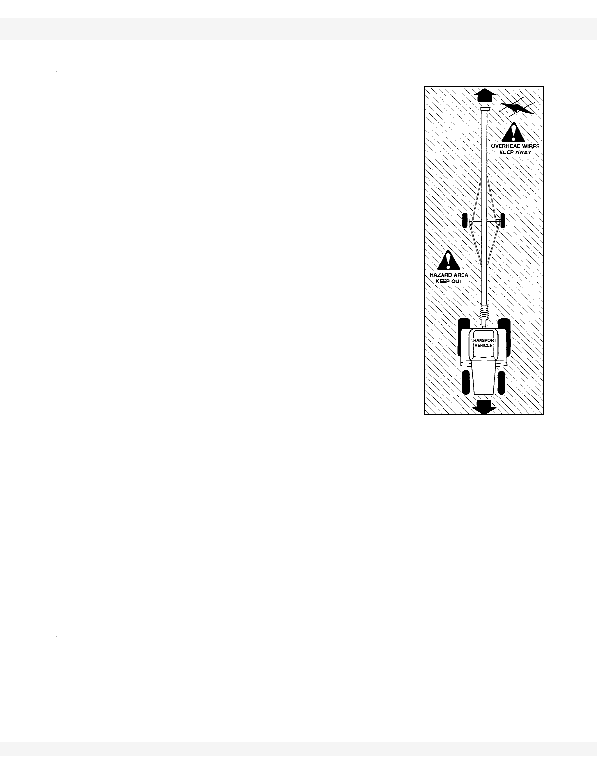
• Do not allow any unauthorized person in the work area.
2.2. ASSEMBLY SAFETY
• Read and understand the instructions to get to know the sub-assemblies and
hardware that make up the equipment before preceding to assemble the
product.
• Do not take chances with safety. The components are large, heavy, and can
be hard to handle. Always use the proper tools, stands, jacks, and hoists for
the job.
• Read and understand assembly instructions before proceeding to assemble
the product.
• Always have two or more people assembling the equipment. Because of the
weight, do not attempt assembly alone.
8 30641 R1
WHEATHEART - GHR & WHR GRAIN AUGERS 2. SAFETY
PTO-SD DRIVE MODEL 2.3. TRANSPORT & PLACEMENT SAFETY
2.3. TRANSPORT & PLACEMENT SAFETY
• Transport auger in full down position with slight tension on cable.
• Properly place hitch pin and securely attach safety
chain. Use a type of hitch pin that will not allow
auger to separate from towing vehicle.
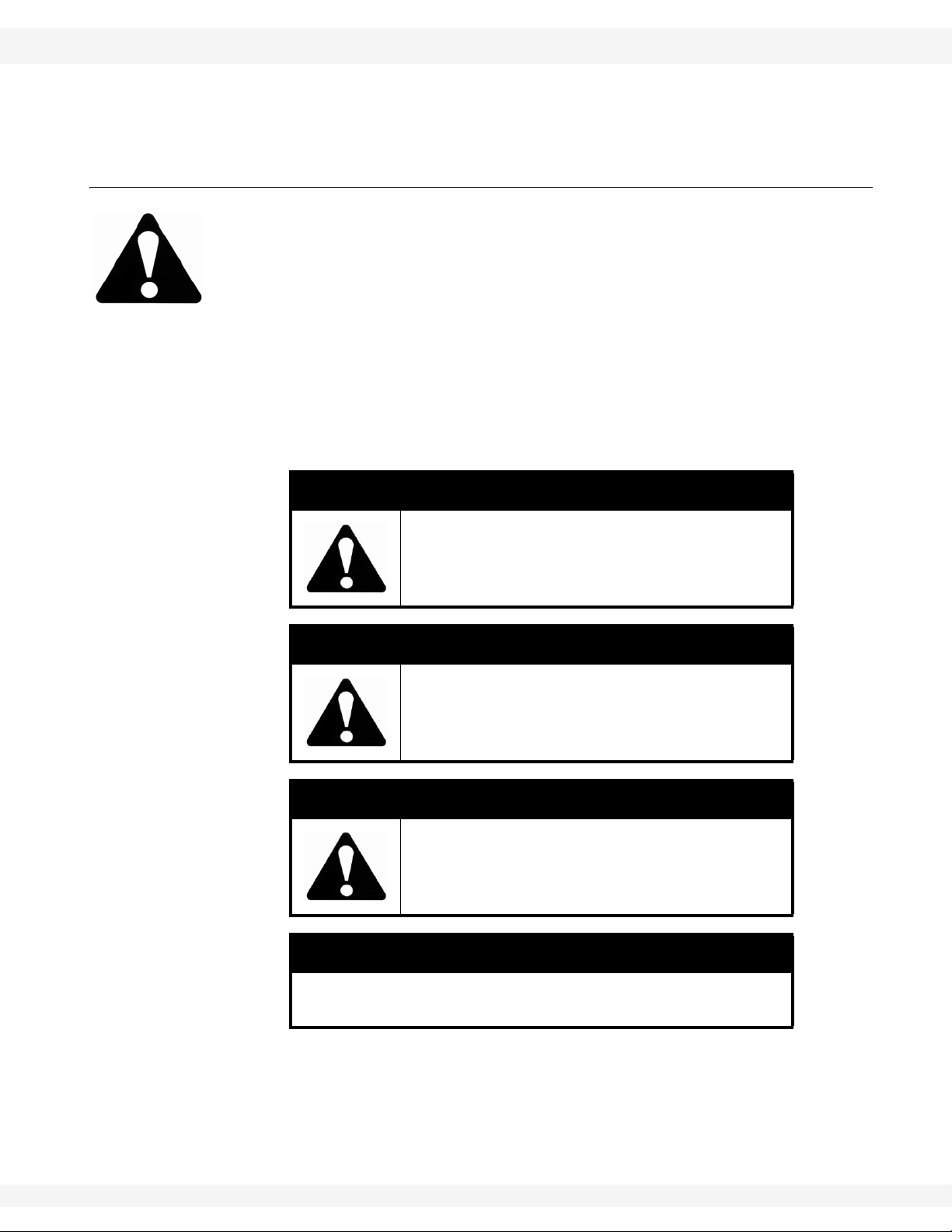
• Always attach an SMV (slow moving vehicle) sign
before transporting auger . Equip the auger with the
necessary lights for transportation where required
by law . Always use hazard warning flashers on the
tractor/towing vehicle when transporting unless
prohibited by law.
• Always travel at a safe speed, never exceeding 15
mph (24 km/hr). Reduce speed on rough surfaces
and be cautious when turning corners or meeting
traffic.
• Before raising/lowering/moving the auger, make
sure the area around the auger is clear of obstructions and/or untrained personnel. Never allow anyone to stand on or beneath auger while
transporting or placing auger.
• Do not transport auger on slopes greater than 20°.
• Wheels must be free to move when raising or lowering auger.
• Never attempt to move auger manually. To do so
will result in serious injury.
• Disconnect PTO driveline from tractor before moving auger or tractor and
secure in transport saddle (where applicable).
• When lowering the auger the track shoe may become stuck; if this happens,
do not continue to turn the winch handle counter-clockwise because it will disengage the brake mechanism and create an unsafe condition. Too much
slack in the cable may also cause the auger to drop suddenly.
• The winch must make a clicking sound when raising auger. If clicking sound
stops, retain grip on handle, lower auger fully, and repair winch.
• After lowering auger, turn handle clockwise two clicks to lock winch brake.
• Always keep a minimum of 3 cable wraps on the winch drum.
• The winch is designed for manual operation only.
2.4. OPERATION SAFETY
• Have another trained person nearby who can shut down the auger in case of
accident. Always work with a second trained person around augers.
• Do not operate with any of the safety guards removed.
• Keep body, hair, and clothing away from moving p art s. Stay away from intake
during operation.
30641 R1 9

2. SAFETY WHEATHEART - GHR & WHR GRAIN AUGERS
2.4. OPERATION SAFETY PTO-SD DRIVE MODEL
• Inspect lift cable before using auger. Replace if frayed or damaged. Make
sure it is seated properly in cable sheaves and cable clamps are secure.
• Operate auger on level ground free of debris. If ground is uneven, anchor the
auger to prevent tipping or upending.
• Augers are not insulated. Keep away from electrical lines. Electrocution can
occur without direct contact.
• Support the discharge end and/or anchor the intake end before operating to
prevent upending.
• Do not use auger as a hoist.
• Empty auger before raising or lowering.
• Lower auger at completion of operation or when not in use. Auger could drop
rapidly in case of cable break or hydraulic failure (where applicable).
• Keep the work area clean and tidy.
• Lock winch before operating auger .
10 30641 R1
WHEATHEART - GHR & WHR GRAIN AUGERS 2. SAFETY
PTO-SD DRIVE MODEL 2.5. MAINTENANCE SAFETY
Figure 2.1
2.5. MAINTENANCE SAFETY
• Shut down and lock out all power before attempting maintenance of any kind.
If applicable, disconnect PTO driveline from tractor or hydraulic hoses on
units with hydraulic drive hoppers.
• After maintenance is complete, replace and secure all safety guards and
safety devices, and if applicable, service doors and cleanout covers.
• Support auger tube before attempting maintenance on the undercarriage
assembly. Auger should be in full down position for maintenance.
• Use only genuine WHEATHEART replacement parts or equivalent. Replacement parts such as intake guards, pulley guards, PTO driveline shields,
winches, and lift cables must meet ASABE standards or serious injury may
30641 R1 11

2. SAFETY WHEATHEART - GHR & WHR GRAIN AUGERS
2.6. PTO SAFETY PTO-SD DRIVE MODEL
result. Use of unauthorized parts will void warranty. If in doubt, contact
WHEATHEART or your WHEATHEART dealer.
• Do not modify any auger components without authorization from WHEATHEART. Modification can be dangerous and result in serious injuries.
2.6. PTO SAFETY
• Never use a PTO driveline without a rotating shield in good working order.
• Ensure PTO driveline is securely attached at both ends before operating.
• Before starting tractor, turn power to PTO to the off position (where applicable).
• Keep body, hair, and clothing away from rotating PTO driveline.
• Ensure the PTO driveline shields turn freely on the PTO driveline.
• Do not exceed operating speed of 540 rpm.
• Keep u-joint angles small and equal. Do not exceed recommended operating
length for PTO driveline.
2.7. SAFETY DECALS
• Keep safety decals clean and legible at all times.
• Replace safety decals that are missing or have become illegible. See decal
location figures that follow.
• Replaced parts must display the same decal(s) as the original part.
• Safety decals are available from your distributor, dealer, or factory.
2.7.1. DECAL INSTALLATION
1. Decal area must be clean and dry, with a temperature above 50°F (10°C).
2. Decide on the exact position before you remove the backing paper.
3. Align the decal over the specified area and carefully press the small portion
with the exposed sticky backing in place.
4. Slowly peel back the remaining paper and carefully smooth the remaining
portion of the decal in place.
5. Small air pockets can be pierced with a pin and smoothed out using the sign
backing paper.
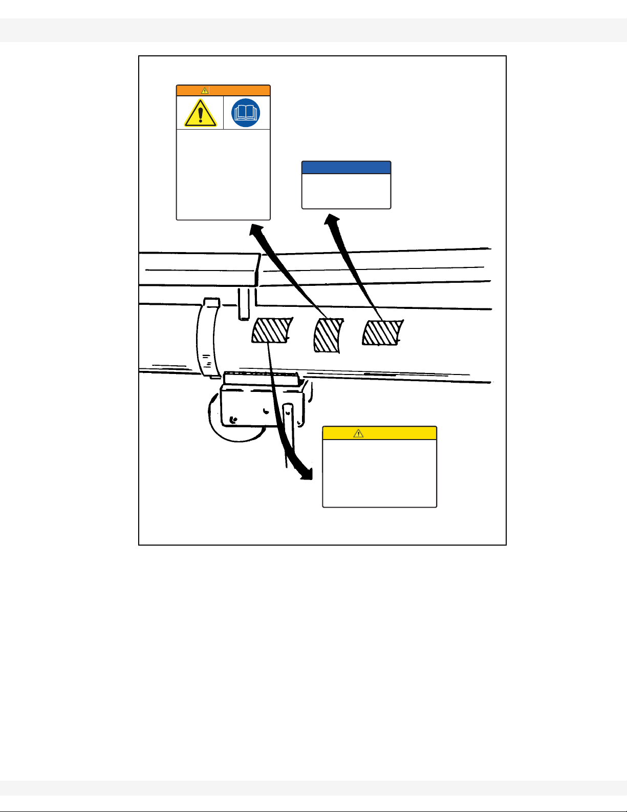
2.7.2. SAFETY DECAL LOCATIONS
Replicas of the safety decals that are attached to the equipment are shown in the
figure(s) that follow. Proper safety procedures require that you familiarize
yourself with the various safety decals and the areas or particular functions that
the decals apply to, as well as the safety precautions that must be taken to avoid
serious injury, death, or damage.
12 30641 R1
WHEATHEART - GHR & WHR GRAIN AUGERS 2. SAFETY
CAUTION
For proper raising and lowering of equipment:
• Tighten brake lock by turning winch handle clockwise
at least two clicks after lowering equipment.
• Lower equipment fully before towing, then rotate
winch handle until cable has light tension.
• D o not lubricate winch brake discs.
• I nspect lift cable periodically; replace if damaged.
• I nspect cable clamps periodically; tighten if
necessary.
17109
Made in Canada
WARNING
To prevent serious injury or death:
• Read and understand the manual before
assembling, operating, or maintaining the
equipment.
• Only trained personnel may assemble, operate, or
maintain the equipment.
• Children and untrained personnel must be kept
outside of the work area.
• If the manual, guards, or decals are missing or
damaged, contact factory or dealer for replacements.
• Lock out power before performing maintenance.
• To prevent equipment collapse, support equipment
tube while disassembling certain components.
• Electric motors must be grounded. Disconnect power
before resetting overloads.
Made in Canada 20807
DECAL
#20807
DECAL
#17109
DECAL
#19960
PTO-SD DRIVE MODEL 2.7. SAFETY DECALS
NOTICE
To prevent damage, wheels must be
free to move when raising or lowering
equipment.
When equipment is positioned, chock
all wheels.
Made in Canada 19960
Figure 2.2
30641 R1 13
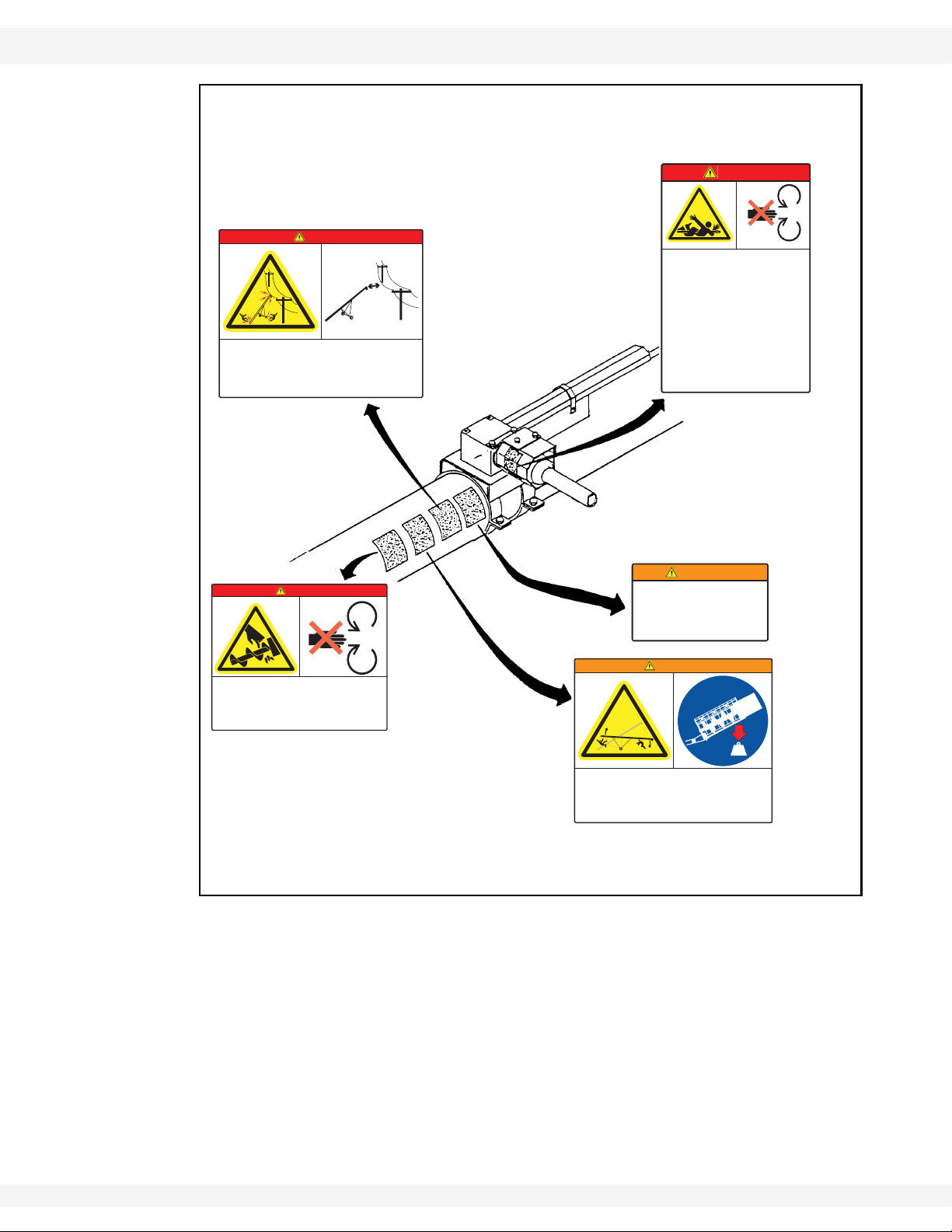
2. SAFETY WHEATHEART - GHR & WHR GRAIN AUGERS
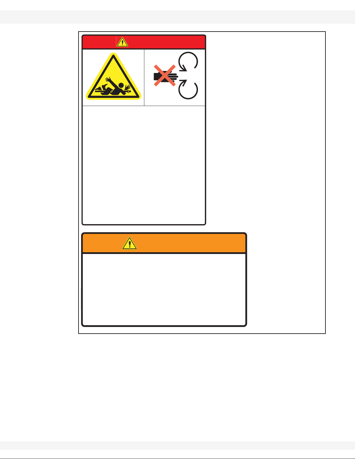
DANGER
ROTATING FLIGHTING HAZARD
To prevent death or serious injury:
• KEEP AWAY from rotating auger flighting.
• DO NOT remove or modify auger flighting
guards, doors, or covers. Keep in good
working order. Have replaced if damaged.
• DO NOT operate the auger without all
guards, doors, and covers in place.
• NEVER touch the auger flighting. Use a
stick or other tool to remove an
obstruction or clean out.
• Shut off and lock out power to adjust,
service, or clean.
20813
Made in Canada
WARNING
TRANSPORT HAZARD
To prevent serious injury or death:
• Securely attach equipment to vehicle with correct
pin and safety chains.
• Use a tow vehicle to move equipment.
31171adanaC ni edaM
DECAL
#20817
DECAL #20819
DECAL
#20811
DECAL
#20813
DECAL #17113
2.7. SAFETY DECALS PTO-SD DRIVE MODEL
DANGER
DANGER
ROTATING PTO DRIVELINE HAZARD
To prevent serious injury or death:
• Keep body, hair, and clothing away from rotating
PTO driveline.
• Do not operate equipment unless all driveline,
tractor, and equipment shields are in place and in
good working order.
• Make certain the driveline shields turn freely on
driveline.
To prevent death or serious injury:
• When operating or moving, keep equipment away from overhead power lines and devices.
• Fully lower equipment before moving.
This equipment is not insulated.
Electrocution can occur without direct contact.
ELECTROCUTION HAZARD
Made in Canada
20817
• Make certain the driveline is securely attached at
both ends.
• Do not exceed operating speed of 540 rpm.
• Keep u-joint angles small and equal. Do not exceed
maximum recommended length for PTO driveline.
Made in Canada 20819
Figure 2.3
To prevent death or serious injury:
• Anchor intake end and/or support
discharge end to prevent upending.
• Auger intake end must always have
downward weight. Do not release until
attached to tow bar or resting on ground.
UPENDING HAZARD
WARNING
• Do not raise auger intake end above tow
bar height.
• Empty auger and fully lower before
moving.
Made in Canada
20811
14 30641 R1
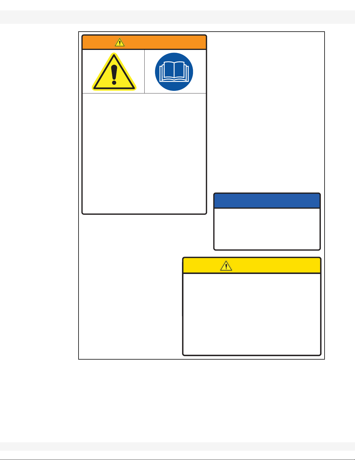
WHEATHEART - GHR & WHR GRAIN AUGERS 2. SAFETY
CAUTION
For proper raising and lowering of equipment:
• Tighten brake lock by turning winch handle clockwise
at least two clicks after lowering equipment.
• Lower equipment fully before towing, then rotate
winch handle until cable has light tension.
• Do not lubricate winch brake discs.
• Inspect lift cable periodically; replace if damaged.
• Inspect cable clamps periodically; tighten if
necessary.
17109
Made in Canada
DECAL #20807
DECAL
#17109
DECAL
#19960
PTO-SD DRIVE MODEL 2.7. SAFETY DECALS
WARNING
To prevent serious injury or death:
• Read and understand the manual before
assembling, operating, or maintaining the
equipment.
• Only trained personnel may assemble, operate, or
maintain the equipment.
• Children and untrained personnel must be kept
outside of the work area.
• If the manual, guards, or decals are missing or
damaged, contact factory or dealer for replacements.
• Lock out power before performing maintenance.
• To prevent equipment collapse, support equipment
tube while disassembling certain components.
• Electric motors must be grounded. Disconnect power
before resetting overloads.
Made in Canada 20807
NOTICE
To prevent damage, wheels must be
free to move when raising or lowering
equipment.
When equipment is positioned, chock
all wheels.
Made in Canada 19960
30641 R1 15
2. SAFETY WHEATHEART - GHR & WHR GRAIN AUGERS
DECAL
#20817
DECAL
#20813
2.7. SAFETY DECALS PTO-SD DRIVE MODEL
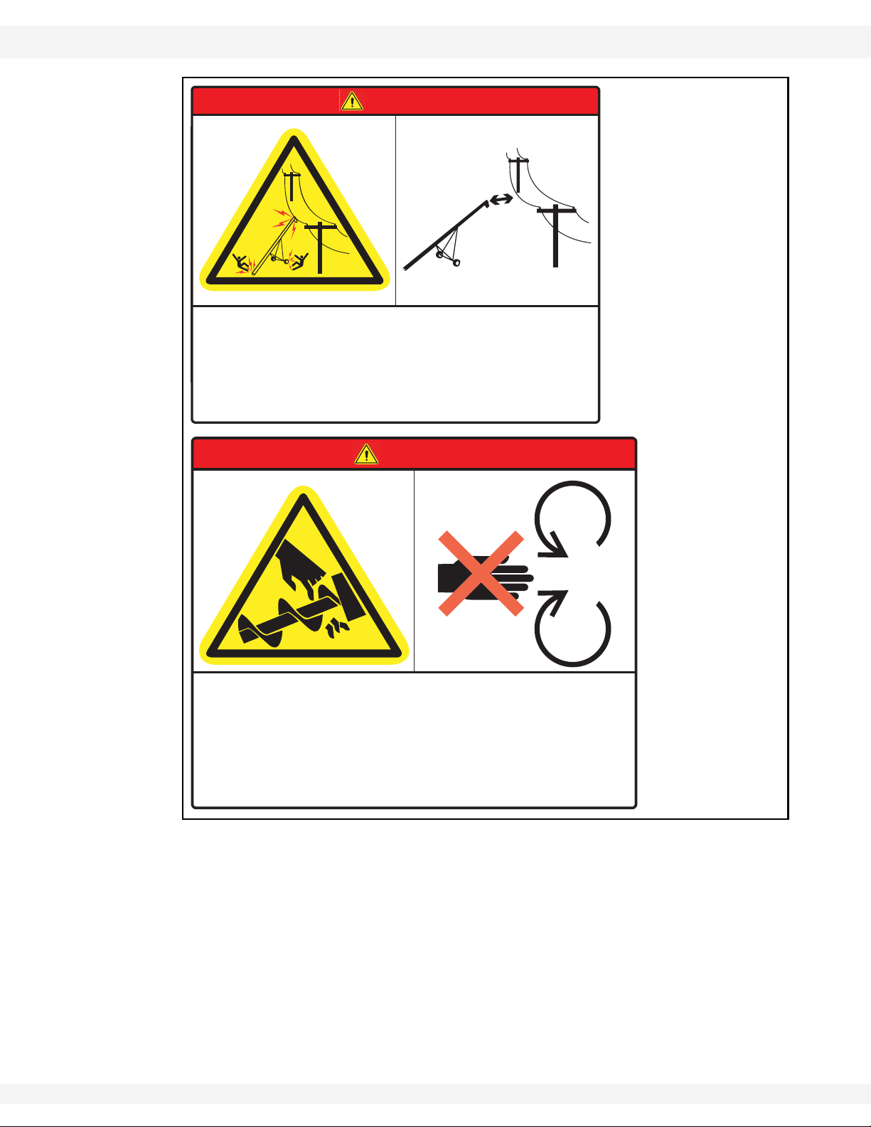
DANGER
ELECTROCUTION HAZARD
To prevent death or serious injury:
• When operating or moving, keep equipment away from overhead power lines and devices.
• Fully lower equipment before moving.
This equipment is not insulated.
Electrocution can occur without direct contact.
20817
Made in Canada
DANGER
ROTATING FLIGHTING HAZARD
To prevent death or serious injury:
• KEEP AWAY from rotating auger flighting.
• DO NOT remove or modify auger flighting
guards, doors, or covers. Keep in good
working order. Have replaced if damaged.
20813
Made in Canada
• DO NOT operate the auger without all
guards, doors, and covers in place.
• NEVER touch the auger flighting. Use a
stick or other tool to remove an
obstruction or clean out.
• Shut off and lock out power to adjust,
service, or clean.
16 30641 R1
WHEATHEART - GHR & WHR GRAIN AUGERS 2. SAFETY
DECAL #20819
DECAL #17113
PTO-SD DRIVE MODEL 2.7. SAFETY DECALS
DANGER
ROTATING PTO DRIVELINE HAZARD
To prevent serious injury or death:
• Keep body, hair, and clothing away from rotating
PTO driveline.
• Do not operate equipment unless all driveline,
tractor, and equipment shields are in place and in
good working order.
• Make certain the driveline shields turn freely on
driveline.
• Make certain the driveline is securely attached at
both ends.
• Do not exceed operating speed of 540 rpm.
• Keep u-joint angles small and equal. Do not exceed
maximum recommended length for PTO driveline.
Made in Canada 20819
WARNING
TRANSPORT HAZARD
To prevent serious injury or death:
• Securely attach equipment to vehicle with correct
pin and safety chains.
• Use a tow vehicle to move equipment.
31171adanaC ni edaM
30641 R1 17

2. SAFETY WHEATHEART - GHR & WHR GRAIN AUGERS
WARNING
UPENDING HAZARD
To prevent death or serious injury:
• Anchor intake end and/or support
discharge end to prevent upending.
• Auger intake end must always have
downward weight. Do not release until
attached to tow bar or resting on ground.
• Do not raise auger intake end above tow
bar height.
• Empty auger and fully lower before
moving.
20811
Made in Canada
DECAL
#20811
2.7. SAFETY DECALS PTO-SD DRIVE MODEL
18 30641 R1
WHEATHEART - GHR & WHR GRAIN AUGERS 3. ASSEMBLY
WARNING Before continuing, ensure you have read and underst and the relevant information
in the safety section. Safety information is provided to help prevent serious injury, death, or
property damage.
PTO-SD DRIVE MODEL 3.1. TUBES & FLIGHTING
3.Assembly
Before beginning assembly, familiarize yourself with all the sub-assemblies and
hardware making up the auger. Have all parts on hand and arrange them for
easy access. Carry out assembly in a large open area with a level surface.
Important: Always have 2 or more people assembling the equipment. Because of the
weight, do not attempt assembly alone.
Augers are available in various combinations. In most cases, the following
instructions will apply to all augers. Where the assembly information varies,
additional instructions will be included and will be indicated with an arrow.
3.1. TUBES & FLIGHTING
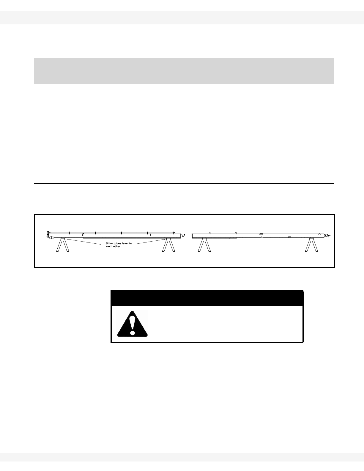
1. Position tube sections. Align tube sections on a flat surface or on a series of
benches.
Figure 3.1
WARNING
Do not drop. Damage to equipment or serious
personal injury will result.
Note: When assembling more than 2 sections, start from spout end and work towards
hopper.
2. Screw or slide lower flight shaft onto upper flight shaft until flight ends butt
together and flighting spiral matches up. Secure with hardware listed in table
below. Repeat, if necessary, for any remaining flight shafts.
30641 R1 19

3. ASSEMBLY WHEATHEART - GHR & WHR GRAIN AUGERS
FOR 8” AND 10” AUGERS, SLIDE
FLIGHTING TOGETHER.
Figure 3.2
Important:
Figure 3.4
Figure 3.3
3.1. TUBES & FLIGHTING PTO-SD DRIVE MODEL
3. Slide tube sections together and secure.
Make sure to align upper and lower track
ends and then tighten bolts. Secure with
hardware in table below.
Track ends must align to allow track shoe to
smoothly slide over track joint. Misalignment
may cause jamming.
Details for connections:
Auger For Flighting Amt. For Tubes Amt.
8”
10”
7/16” x 2-1/4” GR 8 bolts and
locknuts
1/2” x 2-3/4” GR 8 bolts and
locknuts
2 7/16” x 1” bolts and locknuts 8
2 7/16” x 1” bolts and locknuts 8
20 30641 R1

WHEATHEART - GHR & WHR GRAIN AUGERS 3. ASSEMBLY
Figure 3.5
PTO-SD DRIVE MODEL 3.2. TRACK SHOE & TRACK STOP
3.2. TRACK SHOE & TRACK STOP
1. Slide roller track shoe onto
track.
2. Attach the upper track stop
with 7/16” x 1" bolts, heavy
flat washers, and locknuts
(Figure 3.5). For correct
positioning of the upper
track stop, see Table 3.1.
3. Attach the lower angle-iron
track stop (on 36’, 56’, and
61’ augers) with two 7/16” x
1" bolts and locknuts. For
correct positioning of the
lower track stop, see Table
3.2.
Table 3.1 Upper Track Stops
Auger
Length
31’ 8”-10”
36’ 8”
41’ 10" 8”
46’ 8”
51’ 10” 8”
56’ 8”
61’ 8”-10”
71’ 8”-10”
a. Count from upper discharge end of auger. For example, “1st Hole” refers to the first set of
holes in the upper end of the track nearest the discharge end.
1st Hole 2nd Hole 3rd Hole 4th Hole 5th Hole
From Discharge End
a
Upper Track Stop Locations
CAUTION
Failure to locate track stops in the proper
holes can result in damage to auger and/or
personal injury.
4. Slide track shoe along full length of track to make certain there is no binding
and that track ends are properly aligned. The upper and lower tracks must be
aligned to allow track shoe to roll smoothly over this joint.
30641 R1 21
3. ASSEMBLY WHEATHEART - GHR & WHR GRAIN AUGERS
Figure 3.6
3.3. INTAKE HITCH PTO-SD DRIVE MODEL
Table 3.2 Lower Tr ack Stops
Auger
Length
31’ 8”-10”
36’ 8”
41’ 8”-10”
46’ 8”
51’ 8”-10”
56’ 8”
61’ 8”-10”
71’ 8”-10”
a. Count from the lower intake end of auger. For example, “1st Hole”
refers to the first set of holes in the lower end of the track nearest the
intake end.
From Intake End
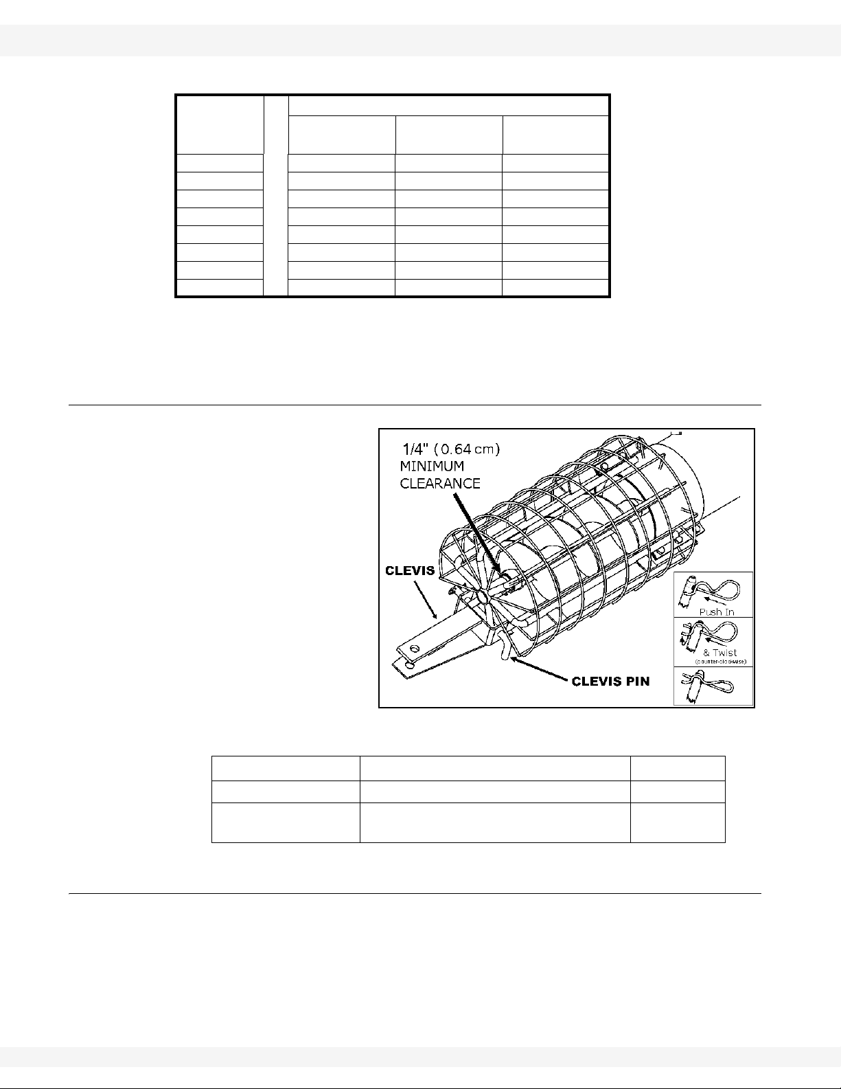
3.3. INTAKE HITCH
1. Clean dirt and paint
from lower flight stub
and intake bushing.
2. Attach intake hitch to
lower auger tube and
tighten securely.
3. Maintain 1/2” (1.27
cm) clearance
between bushing and
end of flight.
4. Attach clevis to intake
hitch with clevis pin
and gripclip.
Lower Track Stop Locations
Welded
Trackstop
a
1st Hole 2nd Hole
3.4. MULTI-STAGE DRIVESHAFT
22 30641 R1
Part Size Amt.
Intake Hitch 7/16” x 1” bolt and locknut 6
Clevis Pin
5/8” for 8”
3/4” for 10”
1
Because some sections of the driveshaft are factory installed, please consult the
table below for correct sequence before completing installation. Then proceed as
follows:
1. Clean paint and dirt from driveshaft end and shaft connectors.
2. Slide shaft connector halfway onto the last pre-installed driveshaft segment.

WHEATHEART - GHR & WHR GRAIN AUGERS 3. ASSEMBLY
PTO-SD DRIVE MODEL 3.5. SHAFT DRIVE GEARBOX
3. Slip lower driveshaft segments through bearings on lower tube section.
Install a Woodruff key, and slide into shaft connector.
• Driveshafts on 10" x 51’, 61’, and 71’ augers require a square key.
4. Place a few drops of oil at each driveshaft bearing to allow for break-in.
5. Tighten all set screws on shaft connectors.
Table 3.3
Auger
Size/Length
8" x 31’
8" x 36’
8" x 41’
8" x 46’
8" x 51’
8" x 56’
8" x 61’
8" x 71’
10" x 31’
10" x 41’
10" x 51’
10" x 61’
Shaft Size
1-1/4”
(3.18 cm)
1-1/4”
(3.18 cm)
1-1/4”
(3.18 cm)
1-1/4”
(3.18 cm)
1-1/4”
(3.18 cm)
1”
(2.54 cm)
1-1/4”
(3.18 cm)
1-1/4”
(3.18 cm)
1-1/4”
(3.18 cm)
1-1/4”
(3.18 cm)
1-1/4”
(3.18 cm)
1-1/4”
(3.18 cm)
Driveshaft Sequence From Discharge End
1st 2nd 3rd
7' 4-1/2”
(2.25 m)
4' 5-1/2”
(1.36 m)
3' 9-1/2”
(1.15 m)
10' 2-1/2”
(3.12 m)
13' 10”
(4.21 m)
1' 3”
(0.38 m)
6' 4”
(1.92 m)
16' 4”
(4.98 m)
--- --- --- 0
--- --- --- 0
--- --- --- 0
6' 4”
(1.92 m)
--- --- 1
3' 5-1/2”
(1.05 m)
4' 5-1/2”
(1.36 m)
6' --- 2
7' 4-1/2”
(2.25 m)
--- --- 0
--- --- 0
--- --- 0
--- --- 0
--- 1
4' 7”
(1.40 m)
--- 2
No. of StrapOn Bearings
2
3.5. SHAFT DRIVE GEARBOX
The PTO-SD auger, depending on size, uses 1 of 2 gearbox assemblies.
GEARBOX MOUNTING PROCEDURE FOR THE FOLLOWING AUGERS
Refer to Figure 3.7 and 3.8.
8” x 31’ 8” x 46’
8” x 36’ 8” x 51’
8” x 41’
1. Remove chain and secure half of the chain coupler to driveshaft using a
Woodruff key.
Important: It is easier to fill gearbox with oil when flat. Fill half full only; do not overfill. See
Table 3.4.
30641 R1 23
3. ASSEMBLY WHEATHEART - GHR & WHR GRAIN AUGERS
Figure 3.8
Figure 3.7
3.5. SHAFT DRIVE GEARBOX PTO-SD DRIVE MODEL
2. Place gearbox assembly on auger tube, leaving a minimum 1/16” clearance
between chain coupler sprockets.
3. Secure gearbox assembly to auger tube with half-tube clamps and four
7/16” x 1" bolts and locknuts.
GEARBOX MOUNTING PROCEDURE FOR THE FOLLOWING AUGERS
• 8" x 56’-61’-71'
• All 10" augers
These augers are equipped with chain couplers (pre-installed on gearbox).
See Figure 3.9.
1. Remove chain and secure half the chain coupler to driveshaft, using a
Woodruff key on 8" augers and a 1/4” x 1-1/2" square key on 10" augers.
Note: It is easier to fill gearbox with oil when flat. Fill half full only; do not overfill. See
Table 3.4.
2. Place gearbox assembly on auger tube then reinstall chain, leaving 1/16”
clearance between chain coupler sprockets. Tighten set screw.
3. Secure gearbox assembly to auger tube with half tube clamps and four
7/16” x 1" bolts and locknuts.
Important: Add EP90 lube oil to the gearbox before operating auger. Failure to do so will
void warranty. Do not overfill. Fill half full only.
Table 3.4
Auger Oil Requirements
all 6”
8” (up to and incl. the 51’)
8” (56’ and up)
all 10”
196 ml
(7 fl oz)
700 ml (25 fl oz)
24 30641 R1
WHEATHEART - GHR & WHR GRAIN AUGERS 3. ASSEMBLY
PTO-SD DRIVE MODEL 3.6. LEFT HAND PTO DRIVE
Figure 3.9
3.6. LEFT HAND PTO DRIVE
To change auger from a right-hand drive to a left-hand drive as seen when
standing at intake end facing the discharge end, proceed as follows:
1. Remove the gearbox guard and the connector/coupler guard and set aside.
Note: Where applicable, remove the coupler chain.
2. Remove the gearbox from mount and place on side (with input shaft pointing
up).
3. Switch drain plug (bottom of gearbox) with air vent plug (top of gearbox) and
reinstall on mount with input shaft to left side and air vent up.
4. Reinstall gearbox.
Important: To reinstall gearbox assembly on auger, see “Shaft Drive Gearbox” on page 23.
30641 R1 25

3. ASSEMBLY WHEATHEART - GHR & WHR GRAIN AUGERS
3.7. PTO DRIVESHIELD PTO-SD DRIVE MODEL
3.7. PTO DRIVESHIELD
1. Clean paint and dirt from gearbox shafts and inside driveline yokes.
2. Slide non-spline end of PTO driveline onto input shaft on gearbox using a
1/4” x 1-1/2” square key. Tighten set screws securely.
Note: The PTO driveline is non-separable type. Do not extend beyond 80".
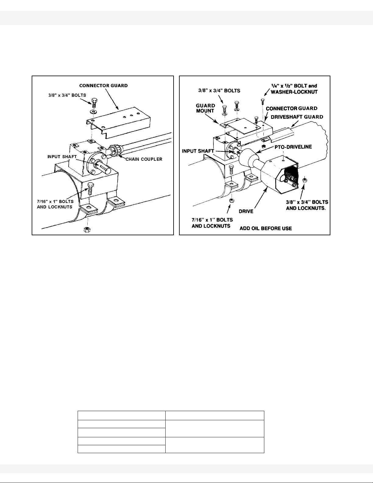
3.8. DRIVESHAFT SHIELD
ALL 8" AUGERS UP TO AND INCLUDING 8" X 51':
See Figure 3.7 and 3.8.
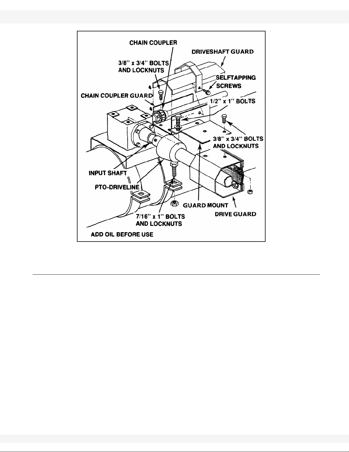
1. Place connector guard on gearbox.
2. Attach driveshield to guard mount with two 3/8” x 3/4” bolts and locknuts, then
slide this assembly over PTO driveline. Attach the guard mount and
connector guard to gearbox with three 3/8” x 3/4” bolts and lockwashers.
3. Attach the driveshaft shields starting from gearbox (refer to Table 3.5 for
correct sequence).
4. Attach driveshaft shield to the connector guard with a 1/4” x 1/2” bolt, washerlocknut, and a punched flat iron plate.
5. Position the driveshaft shields according to Table 3.5, overlapping at bearing
support brackets and at strap-on bearings where applicable. Fasten with
shield straps and self-tapping screws. Do not tighten until all driveshaft
shields are positioned (Figure 3.10).
8" X 56' TO 71' AND ALL 10" AUGERS:
See Figure 3.9.
1. Attach driveshield to guard mount with two 3/8” x 3/4” bolts and locknuts, then
slide this assembly over PTO driveline. Attach to gearbox with 1/2” x 1" bolts
and lockwashers.
2. Attach the chain coupler guard to gearbox base with two 3/8” x 3/4” bolts and
locknuts.
3. Attach the driveshaft shields starting from gearbox (refer to Table 3.5 for
correct sequence).
4. Place driveshaft shield against gearbox and over chain coupler guard, then
secure with a guard strap and two self-tapping screws (Figure 3.9).
5. Position the driveshaft shields according to Table 3.5, overlapping at bearing
support brackets and at strap-on bearings where applicable. Fasten with
shield straps and self-tapping screws. Do not tighten until all driveshaft
guards are positioned (Figure 3.10).
26 30641 R1

WHEATHEART - GHR & WHR GRAIN AUGERS 3. ASSEMBLY
PTO-SD DRIVE MODEL 3.9. DISCHARGE SPOUT
Table 3.5 Driveshaft Shielding Sequence
Auger Size/
Length
8” x 31’ 1
8” x 36’ 1
8” x 41’ 3
8" x 46’ 5
8" x 51’ 2
8" x 56’ 2
8" x 61’ 1
8" x 71’ 4
10" x 31’ 1
10" x 41’ 1
10" x 51’ 11
10" x 61’ 1
10" x 71’ 4
Step 1 Step 2 Step 3 Step 4 Step 5
Qty Length Qty Length Qty Length Qty Length Qty Length
42”
(1.07 m)
42”
(1.07 m)
42”
(1.07 m)
42”
(1.07 m)
42”
(1.07 m)
42”
(1.07 m)
48”
(1.22 m)
42”
(1.07 m)
42”
(1.07 m)
48”
(1.22 m)
48”
(1.22 m)
48”
(1.22 m)
42”
(1.07 m)
1
1
1
4
1
11
2
1
5
3
1
2
1
48”
(1.22 m)
48”
(1.22 m)
48”
(1.22 m)
60”
(1.52 m)
48”
(1.22 m)
48”
(1.22 m)
42”
(1.07 m)
48”
(1.22 m)
48”
(1.22 m)
42”
(1.07 m)
42”
(1.07 m)
42”
(1.07 m)
48”
(1.22 m)
1
1
1
1
6
1
11
1
1
5
-- -- -- -- -- --
11
1
42”
(1.07 m)
42”
(1.07 m)
42”
(1.07 m)
48”
(1.22 m)
60”
(1.52 m)
42”
(1.07 m)
48”
(1.22 m)
42”
(1.07 m)
42”
(1.07 m)
48”
(1.22 m)
48”
(1.22 m)
42”
(1.07 m)
3
4
4
-- -- -- -1
-- -- -- -1
11
-- -- -- -1
1
11
48”
(1.22 m)
48”
(1.22 m)
48”
(1.22 m)
48”
(1.22 m)
42”
(1.07 m)
48”
(1.22 m)
42”
(1.07 m)
42”
(1.07 m)
48”
(1.22 m)
1
(1.07 m)
1
(1.07 m)
1
(1.07 m)
-- --
-- -1
(1.07 m)
-- --
-- -1
(1.07 m)
42"
42"
42"
42"
42"
Figure 3.10
3.9. DISCHARGE SPOUT
1. Attach discharge spout with half tube clamps and 7/16” x 1-3/4” bolts and
locknuts as required. Note that some augers are equipped with weld-on
discharge spouts.
Note: If a safety spout is being used with this auger, the safety release door should be
on the left side of the auger, as determined when standing at intake, facing the
discharge end.
30641 R1 27

3. ASSEMBLY WHEATHEART - GHR & WHR GRAIN AUGERS
3.10. SPROCKET HEAD GEARING PTO-SD DRIVE MODEL
3.10. SPROCKET HEAD GEARING
Change the upper drive sprockets on the following augers:
To obtain the correct flighting speed on the following PT O-SD augers, the 14 and
25 tooth sprockets must be replaced:
• PTO-SD 8" diameter - all lengths up to and including 51’.
Note: Replacement sprockets are included in the PTO-SD shipping carton.
Replace both the upper (14 tooth) and lower (25 tooth) sprocket with 20 tooth
sprockets.
Note: If the PTO-SD augers discussed in this section are changed to a PTO-BD, EMD,
or MD drive, the 14 and 25 tooth sprockets should be reinstalled. This is
necessary to maintain the correct rpm of the flighting.
3.11. UPPER HOUSING LUBRICATION
Fill enclosed upper drive housing with grease.
8” (26' - 51') 750 g 26 oz
8” (56' - 71') 900 g 32 oz
10” (all lengths) 1100 g 40 oz
For continuous use in extreme cold conditions, semi-fluid arctic grease or heavy
oil may be used.
3.12. TRUSS
See Figure 3.11, 3.12, 3.13, and 3.14.
1. Fasten lower truss anchor to bracket.
• use two 7/16” x 1" bolts and locknuts (see Figure 3.11, 3.12, and 3.13 for
location).
Important: On the 8” x 56’ augers, the truss cable must be threaded through the reach-arm
2. Fasten the center truss support bracket on 46’ and 51’ augers with two
7/16” x 1" bolts and locknuts (Figure 3.12).
• The 56’ and 61’ augers require two center truss support brackets, each
fastened with two 7/16” x 1" bolts and locknuts.
• The 71’ auger requires a high truss support center bracket located
between the two standard support brackets. Fasten with two 7/16” x 1"
bolts and locknuts. See Figure 3.13 for correct placement.
3. Attach eyebolt to one end of truss cable with two 5/16” cable clamps. Insert
eyebolt into lower truss anchor and thread on nut a short way.
bracket as shown in Figure 3.11 and then attached to the eyebolts at the lower
truss anchor.
28 30641 R1

WHEATHEART - GHR & WHR GRAIN AUGERS 3. ASSEMBLY
Figure 3.11
PTO-SD DRIVE MODEL 3.12. TRUSS
4. Pull truss cable over truss support brackets, around upper truss anchor and
back over truss support brackets to lower truss anchor, holding it loosely in
place with one 5/16” cable clamp at upper truss anchor, and two 5/16” cable
clamps at each truss support bracket.
Important: Do not tighten cable clamps at this time.
5. The upper end of
augers equipped with
truss cables should
have an upward bow
before being placed
on the transport
undercarriage (auger
tube will straighten
when fully
assembled). Place
supports under the
discharge end until
upward bow is
correct.
• The upward bow
should be about 2”
(5.08 cm) on the
46’ and 51’, 3” (7.62 cm) on the 56’ and 61’, and 5” (12.7 cm) on the 71’
auger.
6. Place other eyebolt onto lower truss anchor and thread on nut a short way.
7. Insert other end of truss cable through this eyebolt. Pull out all slack and
secure with a cable clamp.
8. Tighten eyebolts to take remaining slack out of truss cable and to maintain
the appropriate upward bow. After tension is adjusted, tighten cable clamps
on truss support brackets and upper truss anchor. Check for proper side
alignment.
Important: Once auger is fully assembled, adjust truss cables on all units (because of initial
stretching). Cables may also require adjustment for side alignment.
30641 R1 29

3. ASSEMBLY WHEATHEART - GHR & WHR GRAIN AUGERS
3.12. TRUSS PTO-SD DRIVE MODEL
Figure 3.12
Figure 3.13
30 30641 R1

WHEATHEART - GHR & WHR GRAIN AUGERS 3. ASSEMBLY
PTO-SD DRIVE MODEL 3.12. TRUSS
Figure 3.14
9. For 71’ augers only (Figure 3.14).
a. Fasten short truss anchor (A) to lower auger tube with 7/16” x 1" bolts and
locknuts.
b. Fasten high truss support bracket to mount (C) on bottom of center tube
with 7/16” x 1" bolts and locknuts.
c. Attach eyebolt to one end of truss cable with two 5/16” cable clamps, then
insert eyebolt into short truss anchor and thread on nut a short way.
d. Pull truss cable over truss support bracket, around upper truss anchor (B)
and back over truss support bracket to short truss anchor , holding it loosely
in place with one cable clamp at upper truss anchor and 2 cable clamps at
truss support bracket.
e. Place other eyebolt into short truss anchor and thread nut on a short way.
f. Insert other end of truss cable through this eyebolt. Pull out all slack and
secure with two 5/16” cable clamps.
g. Tighten eyebolt to take remaining slack out of truss cable and adjust
tension to keep auger tube straight. Tighten cable clamps on truss support
bracket and upper truss anchor.
Important: Once auger is fully assembled, adjust truss cables on all units (because of initial
stretching). Cables may also require adjustment for side alignment.
30641 R1 31

3. ASSEMBLY WHEATHEART - GHR & WHR GRAIN AUGERS
3.13. TRANSPORT UNDERCARRIAGE PTO-SD DRIVE MODEL
3.13. TRANSPORT UNDERCARRIAGE
1. To assemble undercarriage, fasten the lower reach arms to axle with three
7/16” x 1" bolts and locknuts on each side.
• The 10" x 51' auger and all 56’, 61’ and 71’ augers require 1/2” x 1-1/4”
bolts and locknuts.
2. Attach long crossmember to bottom of undercarriage brackets as shown in
Figure 3.15, with two 7/16” x 1" bolts and locknuts.
• The 56’, 61’, and 71’ augers require 1/2” x 1-1/4” bolts and locknuts.
Figure 3.15
3. This step applies only to the 8" x 46' and 51' and the 10" x 41' augers.
These augers require extension arms with a short crossmember to be
attached to the lower reach arms (6.). Fasten the short crossmember to lower
reach arms with two 1/2” x 1-1/4” bolts and locknuts. Then fasten the
extension arms with two 7/16” x 1" bolts and locknuts and two 5/8” x 1-1/2”
bolts and locknuts.
4. This step applies only to 8" x 56’-61’-71' and 10" x 51’-61’-71' augers.
Install tubing cross brace supports to the welded brackets on lower reach
arms with five 1/2” x 1-1/4” bolts and locknuts.
5. Wheel hub assembly:
a. Remove any dirt or paint from spindle and hub.
b. Thoroughly pack wheel bearings and cups with a good grade of bearing
grease.
c. Place large bearing into hub and carefully tap in seal.
d. Slip hub onto spindle and insert small bearing.
e. Tighten slotted spindle nut until hub drags slightly. Back off nut about 1/4
turn until hub turns freely.
f. Install cotter pin and dust cap.
32 30641 R1

WHEATHEART - GHR & WHR GRAIN AUGERS 3. ASSEMBLY
Figure 3.16
PTO-SD DRIVE MODEL 3.13. TRANSPORT UNDERCARRIAGE
Note: Installing tires may not leave you with enough clearance to position and attach
undercarriage once auger tube is raised. If so, install wheels after assembly is
complete.
g. Check that pressure of pre-inflated tires matches pressure indicated on tire
sidewall. Mount wheels on hubs and attach with six 1/2” x 1-3/4” wheel
bolts.
6. Fasten upper lift arms to
lower reach arms with
5/8” x 1-1/2” bolts and
locknuts. Do not
overtighten. Tighten snug
only. These bolts act as
pivot points.
• The 8" x 56’-61’-71' and
the 10" x 51’-61’-71'
augers require 3/4” x 2"
bolts and locknuts.
7. Raise the discharge end of
auger with a front end loader and a strong
sling/chain or block and tackle. The height
should be sufficient to clear undercarriage
assembly.
WARNING
Do not remove tube support until auger is fully
assembled.
8. Position transport undercarriage beneath tube assembly and attach lower
reach arms (Figure 3.17) or extension arms (6.) to reach arm bracket on
bottom tube with 5/8” x 1-1/2” bolts and locknuts. Do not overtighten.
Tighten snug only; these bolts act as pivot points.
• The 8" x 56’-61’-71' and the 10" x 51’-61’-71' augers require 3/4” x 2" bolts
and locknuts.
30641 R1 33

3. ASSEMBLY WHEATHEART - GHR & WHR GRAIN AUGERS
Figure 3.17
Figure 3.18
Figure 3.20
Figure 3.19
3.13. TRANSPORT UNDERCARRIAGE PTO-SD DRIVE MODEL
9. Add the Stabilizer Kit as part
of above Step 9 to the
following augers:
8" x 56’-61’-71'
10" x 51’-61’-71'
a. Attach short crossmember
to small frame brackets
loosely with two 1/2” x
1-1/2” bolts and locknuts,
sandwiching the flat
braces (B) between the
short crossmember and
small frame braces on
each side (Figure 3.18).
b. Place undercarriage
beneath the tube
assembly, then position
stabilizer braces (A) as
shown in Figure 3.19 and
attach lower reach arms to reach arm bracket welded on lower end of
auger tube with two 3/4” x 2" bolts and locknuts. Do not overtighten.
Tighten snug only; these bolts act as pivot points.
c. Next, fasten flat braces (B) to first set of holes (furthest from intake) on
stabilizer braces (A) with one 7/16” x 1-3/4” bolt and locknut. Place one
7/16” x 1" bolt and locknut in the other hole of the stabilizer brace.
34 30641 R1

WHEATHEART - GHR & WHR GRAIN AUGERS 3. ASSEMBLY
Figure 3.21
Figure 3.22
PTO-SD DRIVE MODEL 3.14. WINCH & LIFTCABLE
Important: Where applicable, make sure that the lower reach arms are attached to the
proper reach arm bracket (Figure 3.12 and 3.13).
10. Attach upper lift arms to roller
track shoe with one
5/8” x 6-1/2” bolt and locknut.
Do not overtighten. Tighten
snug only; this bolt acts as a
pivot point (Figure 3.21).
• The 8" x 56’-61’-71' and
the 10" x 51’-61’-71'
augers require a 3/4” x
6-1/2” bolt and locknut.
11. The 8" x 56’-61’-71' and the
10" x 61’-71' augers require
additional tubing cross
braces mounted to the
upper lift arms.
• To correctly assemble,
slip the tube clamps over
the flat pressed ends of
the lift arms (where they
are attached to the
frame) and loosely
attach the tubing cross cclamp vise grip to
squeeze and hold the
tube clamps in position
for attachment to the tubing cross braces.
• Once in position, tighten
the bolts (Figure 3.22).
3.14. WINCH & LIFTCABLE
30641 R1 35
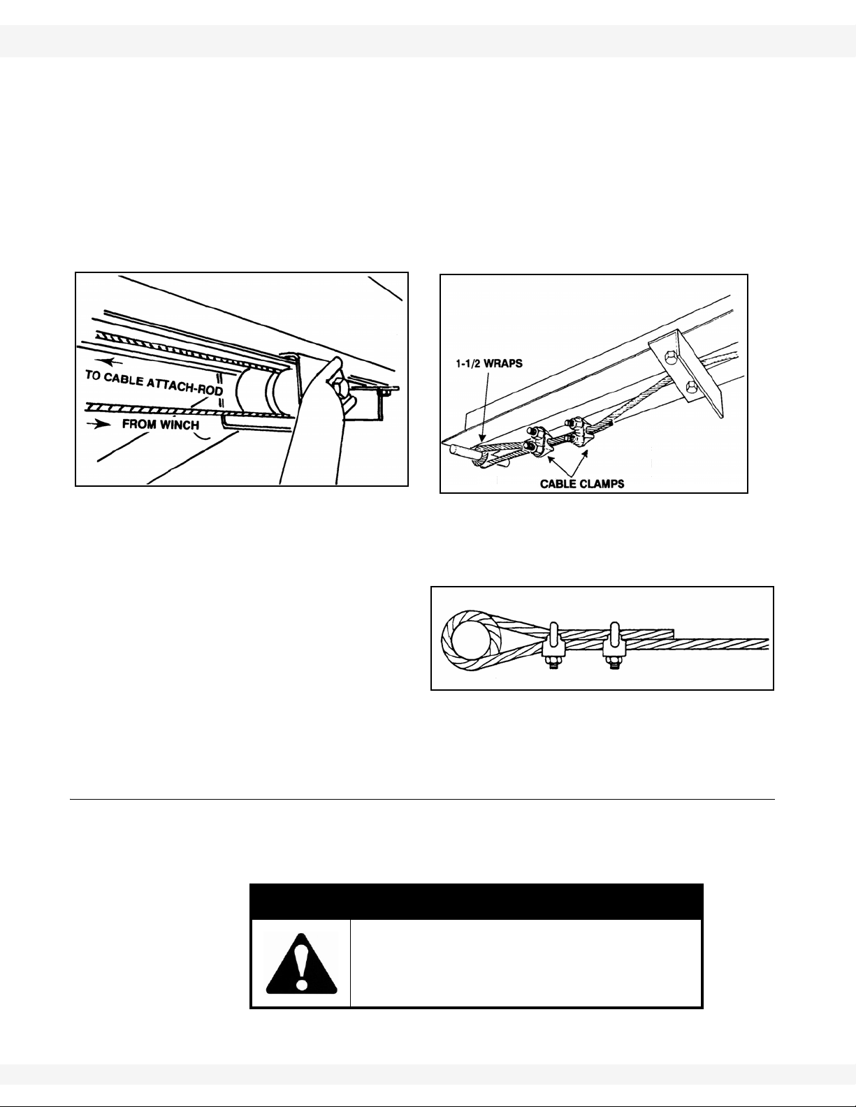
1. Attach cable to winch using one of the 2
methods shown, depending on supplied
winch.
• If method 2 is used, the nut must be on
the outside of the drum to prevent damage to the cable. Leave about one inch
(2.54 cm) of cable extending past the
clamp. Cable must leave winch from
bottom side.
3. ASSEMBLY WHEATHEART - GHR & WHR GRAIN AUGERS
Figure 3.24
Figure 3.23
Figure 3.25
3.14. WINCH & LIFTCABLE PTO-SD DRIVE MODEL
Important: Winch handle must be positioned on the left side of the auger (determine left by
standing at the intake end, facing the discharge end).
2. Attach winch to winch mount with three 3/8” washer locknuts.
Important: Winch handle must be positioned on the left side of the auger (determine left by
standing at the intake end, facing the discharge end).
Note: If auger has more than 1 winch mount, use the bracket nearest the intake end.
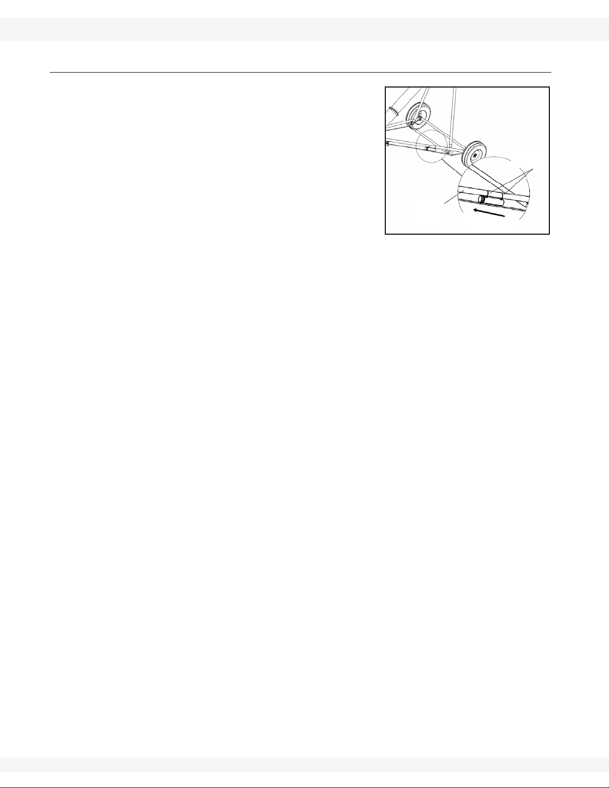
3. Thread lift cable under and around roller on track shoe, then back to cable
attach rod welded to lower end of track.
Note: On auger equipped with a lower angle-iron track stop, the cable must be
threaded between track stop and auger tube so cable rests on top of the track
stop (See Figure 3.24).
4. Wrap cable 1-1/2 times
around the cable attach rod
and secure with two 1/4”
cable clamps. Position
cable clamps as shown in
Figure 3.24 and 3.25.
Tighten clamps securely.
Note: Make certain cable is properly seated in cable groove before raising auger.
3.14.1. WINCH HANDLE
This auger may use one of several different winch models. Before installing
handle on the main winch assembly , check the model number st amped on winch
housing and follow the correct set of instructions.
CAUTION
Winch handle assembly must follow the
instructions below. Improper assembly will
result in sudden winch failure causing
damage to equipment and/or personal injury.
36 30641 R1
WHEATHEART - GHR & WHR GRAIN AUGERS 3. ASSEMBLY
Figure 3.26
Important:
Figure 3.27
Important:
PTO-SD DRIVE MODEL 3.15. TRANSPORT SADDLE
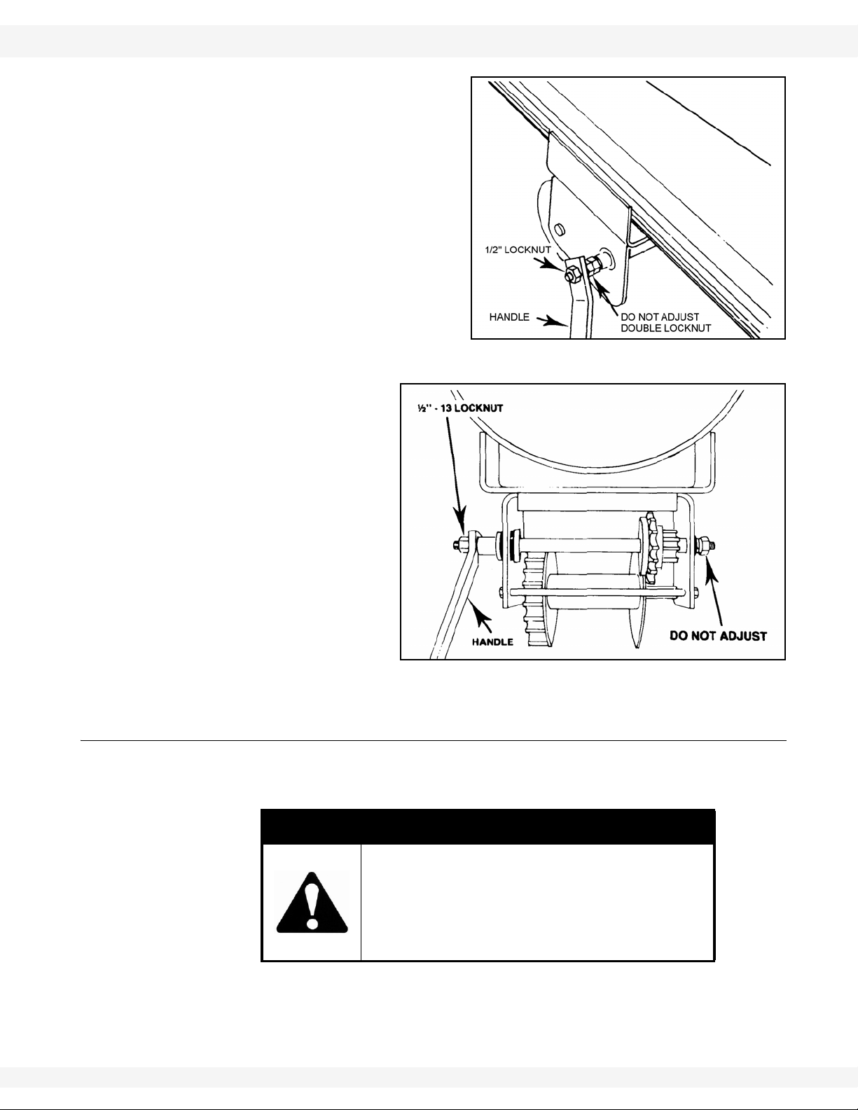
MODEL K1051 & K1550
See Figure 3.26.
1. Slide handle over flat sides of
input shaft.
2. Fasten with 1/2” locknut.
Do not remove or loosen the double
locknut on the input shaft: it is an
important part of the brake system of
the winch.
MODEL K2550
See Figure 3.27.
1. Slide handle over flat
sides of input shaft.
2. Fasten with 1/2”
locknut.
Do not remove or loosen
the locknut on brake side
of winch: it is an important
part of the brake system of
the winch.
3.15. TRANSPORT SADDLE
Install transport saddle for the PTO driveline to auger tube about 3’ above
gearbox assembly. Secure with two 7/16” x 1" bolts and locknuts.
DANGER
30641 R1 37
Never use a PTO driveline without a rotating
guard in good working order.
Do not exceed maximum recommended
operating length or angularity of PTO
driveline.
Important: Do not cover decals with gearbox or transport saddle. Replace any decal that is
not clearly visible, available at no charge upon request.
3. ASSEMBLY WHEATHEART - GHR & WHR GRAIN AUGERS
LOWER
REACH
ARMS
PLASTIC
ZIP TIES
C
A
P
F
A
C
I
N
G
I
N
T
A
K
E
Figure 3.28
Note:
3.16. PLASTIC MANUAL HOLDER PTO-SD DRIVE MODEL
3.16. PLASTIC MANUAL HOLDER
Before beginning installation, ensure that all
winch / auger lift controls are locked in place
and shut down and/or lock out auger.
1. Attach holder to the lower fr ame arms.
Manual holder must be accessible at all
times, whether frame is up or down.
2. The manual holder cap must face up
(towards the intake end). Attach manual
holder with supplied zip ties. Tighten the zip
ties, securing the holder in place.
Where possible, attach the zip ties above a
frame brace tab to prevent the manual holder
from slipping down the lower frame arms.
38 30641 R1

WHEATHEART - GHR & WHR GRAIN AUGERS 3. ASSEMBLY
PTO-SD DRIVE MODEL 3.17. MODEL DECAL PLACEMENT
3.17. MODEL DECAL PLACEMENT
Figure 3.29
Important: Do not cover any existing safety or instruction decals with the model decals.
For most decal placement, follow the figure above. Apply decals to both sides of
auger tube.
Lower Tubes: Place decals just below the angle flange, centered on the tube.
Decals must be easily seen from the ground when auger assembly is complete.
(For 36' augers, the model decal can be located in the center of the lower tube.)
Upper Tubes: Place Wheatheart decals in the center of the upper tube, where
they are easily seen from the ground when auger assembly is complete. For the
GHR130/SA130/SA130 FLEX series, the Wheatheart decal is located at the top
end of the upper middle tube.
30641 R1 39

3. ASSEMBLY WHEATHEART - GHR & WHR GRAIN AUGERS
3.17. MODEL DECAL PLACEMENT PTO-SD DRIVE MODEL
40 30641 R1

WHEATHEART - GHR & WHR GRAIN AUGERS 4. TRANSPORT & PLACEMENT
WARNING Before continuing, ensure you have read and underst and the relevant information
in the safety section. Safety information is provided to help prevent serious injury, death, or
property damage.
PTO-SD DRIVE MODEL 4.1. TRANSPORT PROCEDURE
4.Transport & Placement
4.1. TRANSPORT PROCEDURE
Follow all safety precautions when transporting the auger and use a proper
towing vehicle.
1. If auger is raised, place in full down position. The roller track shoe should be
seated against the upper track stop with slight tension on the lift cable. Refer
to “Lowering & Completion” on page 48.
2. Lock winch: turn handle clockwise until 2 clicks are heard.
Important: The winch must have a minimum of 3 wraps of cable on drum when auger is in
transport position.
3. Place and secure hitch pin and safety chain. The safety chain should be
threaded though handle on the lower tube and wrapped around auger tube
before attaching to the towing vehicle (Figure 4.1).
Figure 4.1
Important: Use a type of hitch pin (see Figure 4.1) that will not allow auger to separate from
towing vehicle.
WARNING
If auger wheels are partially or fully buried in
snow or grain, failure to clear area around the
wheels before moving may cause damage to
the auger or result in serious injury.
30641 R1 41

4. TRANSPORT & PLACEMENT WHEATHEART - GHR & WHR GRAIN AUGERS
4.2. PLACEMENT PROCEDURE PTO-SD DRIVE MODEL
4. Beware of overhead obstructions and electrical wires and devices. The PTOSD augers have minimum clearances from 9' (2.74 m) to 15'6" (4.72 m) in
normal transport position.
5. Refer to “Transport & Placement Safety” on page 11 for important safety
information before towing.
4.2. PLACEMENT PROCEDURE
1. Ensure towing hitch is in place and secure.
Important: Use a type of hitch pin (see Figure 4.1) that will not allow auger to separate from
towing vehicle.
2. Before raising or positioning auger, make sure that entire area in line of
travel, both on the ground and overhead, is clear of any obstructions or
electrical wires.
WARNING
If auger wheels are partially or fully buried in
snow or grain, failure to clear the area around
the wheels before moving may cause damage
to the auger or result in serious injury.
3. Ensure auger is on reasonably level ground when raising, lowering, or
positioning.
Note: Make certain cable is properly seated in cable groove before raising auger. Refer
to Figure 3.25.
4. To raise auger, turn winch handle clockwise. Use a firm grip on winch handle;
do not release unless the ratchet pawl is fully engaged.
NOTICE
Do not turn winch handle counter-clockwise except when
lowering auger or severe damage to winch will occur.
Important: Winch must make clicking sound when raising auger. If clicking stops, retain grip
on handle, lower auger fully, and repair ratchet.
Note: The PTO driveline is a non-separable type. Remove from tractor and secure in
transport saddle on auger before moving tractor away from auger.
5. Move the auger into working position slowly. Do not unhitch and attempt to
move auger by hand.
WARNING
Never attempt to increase height of auger by
positioning wheels on number, blocks, or by
any other means. To do so will result in
damage to equipment and/or personal injury.
42 30641 R1

WHEATHEART - GHR & WHR GRAIN AUGERS 4. TRANSPORT & PLACEMENT
PTO-SD DRIVE MODEL 4.2. PLACEMENT PROCEDURE
6. Once auger is in position, chock wheels on both sides and apply the park
brake on the tractor (or chock its wheels as well) to prevent movement during
operation.
Important: When releasing auger from the towing vehicle, test the intake end for downward
weight. Do not raise the intake end above drawbar height. When the intake end
is elevated too high with auger in raised position, the balance of weight quickly
transfers to the discharge end, causing it to upend. Ensure proper anchoring/
support.
7. When operating auger in the raised position, rest the discharge end lightly on
the bin roof, or tie to bin to prevent wind from toppling auger. When operating
the auger in a freestanding position, anchor the intake end.
8. Anchor and/or support auger during operation.
• When lower half of auger empties of grain, the weight balance transfers
to upper end of auger, which can cause upending.
9. See “Operation” on page 45 for correct lowering procedure.
CAUTION
Do not use auger as a hoist to raise any object
regardless of weight. This will create an
unsafe condition and will void warranty.
30641 R1 43

4. TRANSPORT & PLACEMENT WHEATHEART - GHR & WHR GRAIN AUGERS
4.2. PLACEMENT PROCEDURE PTO-SD DRIVE MODEL
44 30641 R1

WHEATHEART - GHR & WHR GRAIN AUGERS 5. OPERATION
WARNING Before continuing, ensure you have read and underst and the relevant information
in the safety section. Safety information is provided to help prevent serious injury, death, or
property damage.
PTO-SD DRIVE MODEL 5.1. PRE-OPERATIONAL CHECKLIST
5.Operation
5.1. PRE-OPERATIONAL CHECKLIST
Before operating auger each time, the operator must confirm the following:
• All fasteners are secure as per assembly instructions.
• PTO driveline is connected and secure.
• PTO driveline shield rotates freely.
• Lift cable is not frayed or damaged.
• Lift cable is properly seated in cable sheaves.
• Cable clamps are secure.
• Tube alignment is reasonably straight.
• Auger wheels are chocked, and if necessary, tractor wheels are chocked
or the parking brake has been engaged.
• Intake area and discharge spout are free of obstructions.
• Proper maintenance has been performed.
5.2. AUGER DRIVE & LOCKOUT PROCEDURE
Drive Type Before Operation Lockout
PTO Driveline Before starting, ensure:
• PTO driveline is securely attached to the
tractor and jackshaft
• tractor park brake is engaged and/or wheels
are chocked
• you are not exceeding the maximum operat-
ing length of 80” (2032 mm) of the PTO
driveline or maximum angle of 15°
• PTO drive on the tractor is in the off position
Shut off tractor’s engine
and remove key from
tractor.
• If removing key is
impossible, remove
PTO driveline from
tractor.
30641 R1 45

5. OPERATION WHEATHEART - GHR & WHR GRAIN AUGERS
5.3. OPERATION PROCEDURE PTO-SD DRIVE MODEL
5.3. OPERATION PROCEDURE
5.3.1. START-UP & BREAK-IN
1. Properly place auger and complete the pre-operational checklist at the
beginning of this chapter. If everything is satisfactory, prepare for a 30-minute
operation at half speed.
2. Correctly position portable grain hopper secure it to the auger with both
straps (where applicable).
Important: Anchoring and/or support auger during operation. When lower half of auger
empties of grain, the weight balance transfers to the upper end of auger, which
can cause upending.
CAUTION
Do not start auger until area is clear of all
unauthorized personnel.
Do not exceed 540 rpm on the PTO.
3. Start tractor and engage PTO driveline, then feed grain to auger. If auger
functions normally, check at varying speeds for a period of 30 minutes.
Important: When starting auger for the first time, be prepared for an emergency shutdown in
case of excessive vibration or noise. Note that auger may run rough until tube is
polished.
4. Upon completion of initial run, shut down auger (see “Shutdown” on page 47
for further instruction).
5. Lock out tractor and conduct a complete inspection of auger following the
checklist at the beginning of this chapter.
After the initial start-up and inspection, the auger should be shut down and
inspected at least three more times during the first 10 hours of operation.
Keep operation of empty auger to a minimum, as this results in excessive wear.
Once auger is broken in, the checklist should be a part of the daily routine before
operating auger.
5.3.2. OPERATING WITH A FULL LOAD
1. When operating the auger , always work with a second person in a position to
monitor the operation and initiate a shutdown in case of emergency.
2. Monitor the auger during operation for abnormal noises or vibrations.
3. Shut off all power before making adjustments, servicing, or clearing the
machine.
46 30641 R1

WHEATHEART - GHR & WHR GRAIN AUGERS 5. OPERATION
USE OF GRAIN SPREADERS: Many grain spreaders cannot handle the large
capacity of some augers. Some augers plug, causing damage to the flighting
and other drive components. This type of damage is not covered by warranty.
Hints on how to avoid this...
• Get a larger spreader, if available.
• Remove the spreader.
• Make sure spreader is turned on.
• Center auger spout on spreader.
• Do not lower auger spout into spreader.
• Suspend the spreader from bin ceiling leaving extra room for excess
grain to flow over the spreader.
BIN LEVEL INDICATORS: These augers are fast and bins fill up quickly. A full
bin will cause auger to plug, which can damage the flighting and other drive
components. Installing quality grain-level indicators on your bins will allow you to
monitor bin filling and help prevent damage to your auger.
PTO-SD DRIVE MODEL 5.3. OPERATION PROCEDURE
DANGER
Rotating Flighting Hazard!
To prevent death or serious injury:
• Keep away from rotating auger flighting.
• Do not remove or modify auger flighting
guards, doors, or covers. Keep in good
working order. Have replaced if damaged.
• Do not operate the auger without all
guards, doors, and covers in place.
• Never touch the auger flighting. Use a
stick or other tool to remove an obstruction or clean out.
• Shut off and lock out power to adjust, service, or clean.
5.3.3. SHUTDOWN
NORMAL SHUTDOWN:
1. Near the end of a load, decrease auger speed until all grain is clear of
machine.
2. When auger is clear of grain, disengage PTO drive.
3. Shut down and lock out tractor.
EMERGENCY / FULL-TUBE RESTART:
1. If the auger is shut down for an emergency, lock out tractor before correcting
the problem.
30641 R1 47

5. OPERATION WHEATHEART - GHR & WHR GRAIN AUGERS
LOWERING
1. Disconnect PTO driveline from tractor before lowering.
2. Ensure area beneath auger is clear.
3. Turn winch counterclockwise to lower (there will be no clicking sound when
lowering).
4. After lowering, turn handle clockwise until you hear 2 clicks to lock brake.
• Use a firm grip on handle. Do not release unless the ratchet pawl is fully
engaged.
• The winch is designed for manual operation only.
• When lowering, never continue to turn handle counterclockwise if the
cable does not keep moving out under load. This will disengage the
brake mechanism and create an unsafe condition. If this happens, winch
in slack cable and correct problem.
Do not leave auger in raised position when not in use. Auger could drop rapidly
due to a cable break. High winds may also upset auger.
5.3. OPERATION PROCEDURE PTO-SD DRIVE MODEL
• If the problem is plugging, clear as much of the grain as possible using a
piece of wood, wet/dry vac, or other tool before restarting auger. Do not
reach in and use your hands even if the tractor has been locked out.
2. If auger tube is full of grain, do not restart at full speed. Engage PTO at low
rpm, gradually increasing power until normal operating speed is reached.
NOTICE
Starting the auger when there is grain blockage will result in
damage.
5.3.4. LOWERING & COMPLETION
After operation:
1. Clean entire work area.
2. Remove all supports and chocks.
3. Move auger out of working position and lower fully (see shaded box that
follows for lowering procedure).
4. Move auger to the next work area or to a storage area and then clean out.
48 30641 R1
5. Clean out auger.
a. Shut off tractor engine and lock out power.
b. Manually clean out grain with a piece of wood, vacuum cleaner, or other
tool. Do not use hands.
c. If auger has been used to transport fertilizer, it should be cleaned out to
prevent corrosion. The easiest way to prevent corrosion is to run a load of
grain through it after transporting fertilizer.
6. Prepare for transport and placement or storage (see appropriate chapters for
more information).

WHEATHEART - GHR & WHR GRAIN AUGERS 6. MAINTENANCE & STORAGE
WARNING Before continuing, ensure you have read and underst and the relevant information
in the safety section. Safety information is provided to help prevent serious injury, death, or
property damage.
PTO-SD DRIVE MODEL 6.1. GENERAL MAINTENANCE PROCEDURES
6.Maintenance & Storage
Proper maintenance habits on the PTO-SD auger mean a longer life, better
efficiency, and safer operation.
6.1. GENERAL MAINTENANCE PROCEDURES
Please follow the guidelines below.
Area Maintenance Procedure Frequency
General
General
Lift Cable
Wheel Hubs Repack with lithium-based grease. Every 2–3 years
Tire Pressure
PTO Driveline
Upper Chain Drive
Drive Chain Adjustment
Intake Bushing Lubricate. Daily
Gearbox
While auger is in use, observe the “Pre-Operation Checklist”
on page 51.
Check all operating, lifting, and transport components.
Replace damaged or worn parts before using auger.
For replacement instructions, see Assembly Section.
Check and replace if frayed or damaged. Make sure cable
clamps are secure.
Check with a pressure gauge. Pressure should be maintained according to sidewall recommendations.
Lubricate both universal joints.
Lubricate the center portion of the driveline (grease fitting is
beneath shield) on a yearly basis.
Fill enclosed upper drive housing to plug level with grease.
GHR 80 x 31’–51’: 750 g (26 oz)
GHR 80 x 56’–71’: 900 g (32 oz)
GHR 100: 1100 g (40 oz)
For continuous use in extreme cold, semi-fluid arctic grease
or heavy oil may be used.
Maintain 1/4” - 1/2” (0.64 cm - 1.27 cm) chain deflection.
To adjust, loosen bolts on top bearing in the upper drive
housing, adjust chain to proper tension, and re-tighten
bolts
Maintain oil level at half full (center of cross shaft) with EP90
lube oil.
Gearbox should be level when checking or refilling
do not overfill
Daily
Regularly
Periodically
Monthly, or if it
seems low
After every 8
hours of operation
Yearly
Regularly
Regularly
Oil must be
added to gearbox
before operating, and then regularly as needed
30641 R1 49

6. MAINTENANCE & STORAGE WHEATHEART - GHR & WHR GRAIN AUGERS
6.2. GENERAL STORAGE PROCEDURES PTO-SD DRIVE MODEL
Area Maintenance Procedure Frequency
Keep a film of grease on gears. Regularly
Winch
Note: Service
winch with auger in
fully lowered position and cable
slack.
Truss Cables Adjust to keep auger tube reasonably straight. As necessary
Oil the ratchet pawl pivot, bushings, and pinion threads.
Do not get oil or grease on brake discs.
Replace brake discs if less than 1/16” (1.6 mm) thick. As required
Check for proper ratchet pawl operation.
When cranking in (clockwise) = loud clicking
When cranking out (counterclockwise) = no clicking and
ratchet pawl fully engaged into gear teeth
Occasionally
Regularly
6.2. GENERAL STORAGE PROCEDURES
TO PROTECT AUGER IN STORAGE DURING THE OFF-SEASON:
1. Lower the auger to full down position with slight tension on the cable.
2. Lubricate all grease fittings according to the maintenance procedure.
3. Inspect auger for damage and note any repairs required. Order replacement
parts from your dealer.
4. Check tire pressure and inflate if necessary. See tire sidewall for recommendations.
5. Clean and re-lubricate spline on PTO driveline. Cover PTO driveline with
plastic bag to protect it from the weather and place in the transport saddle.
6. Tow auger to storage area. Park and chock wheels.
CAUTION
Support discharge end of auger before
removing or replacing any parts on the
undercarriage.
TO PREPARE AUGER FOR USE AFTER STORAGE:
1. Check tire pressure and inflate if necessary. See tire sidewall for recommen-
dations.
2. Tow auger to work site.
3. Remove cover from spline of PTO driveline and re-lubricate.
4. Check oil level in gearbox and refill if necessary (half full only).
5. Replace any damaged parts and decals.
6. Conduct general maintenance procedures before using auger.
7. Before raising auger after storage, make certain cable is in good condition,
replacing it if frayed or damaged. Also make sure cable is properly seated in
roller track and that cable clamps are secure.
8. On augers equipped with lubricated upper drive, check level of lubrication
annually and add as needed. Refill to plug level.
50 30641 R1

WHEATHEART - GHR & WHR GRAIN AUGERS 6. MAINTENANCE & STORAGE
PTO-SD DRIVE MODEL 6.2. GENERAL STORAGE PROCEDURES
Note: Use only genuine Wheatheart replacement parts or equivalent. Replacement
parts such as intake guards, pulley guards, PTO driveline shields, winches and
lift cables Must meet ASAE standards or serious injury may result. Use of
unauthorized parts will void warranty. If in doubt, contact Wheatheart or your
Wheatheart dealer. Do not modify any auger components.
30641 R1 51

6. MAINTENANCE & STORAGE WHEATHEART - GHR & WHR GRAIN AUGERS
6.2. GENERAL STORAGE PROCEDURES PTO-SD DRIVE MODEL
52 30641 R1

WHEATHEART - GHR & WHR GRAIN AUGERS 7. TROUBLESHOOTING
PTO-SD DRIVE MODEL
7.Troubleshooting
.
Problem Possible Cause Remedy
Spray penetrating lubricant between shaft and
Excessive
noise or vibration.
*Remember to
follow proper
break-in procedures—auger
may run rough
until tube is polished. If noise
is extreme from
outset or continuous after
several loads of
grade are fed,
continue with
troubleshooting below
Shear bolts
fail repeatedly.
Chatter from wooden bearings.
Truss cables incorrectly
adjusted.
Flighting peeled back due to
plugging.
Top drive inadequately lubricated.
Bent flighting sections.
Obstruction in tube.
Incorrect shear bolt type.
Shear bolt hole worn out-ofround.
Corn spreaders in bin unable to
keep up with auger output.
Flighting peeled back as a result
of plugging.
Driveline failure (bearing, gearbox, etc.).
bearing surface. Bearings will break in over
time.
*If replacement of a bearing becomes necessary , split bearings are available to a void having
to slide all bearings off driveshaft.
Support end of auger and adjust cables so
auger is flat or curves slightly upwards.
Inspect spout end of auger for flight condition.
Remove and replace flight sections as necessary.
Fill to appropriate level with grease.
Top drive is not designed to be filled with oil.
Support auger and remove all flight sections.
Check for straightness of flight stubs by rolling
across flat concrete section. Straighten stub or
replace as necessary. Take care not to bend
flighting when reinstalling.
Visually inspect for cloth or trash wrapped
around flighting, or buildup of gum from oily
crops such as flax or canola.
Replace with correct part number. WHEATHEART shear bolts are specifically designed to
provide correct driveline protection.
Frequent use of the incorrect shear bolt size can
wear the mounting hole creating a “scissor
effect,” which will require replacement of the
affected parts.
Slow down auger or remove corn spreaders.
Occurs when bin has overfilled, or corn spread-
ers restrict end of discharge. Inspect flighting at
discharge end of auger. If necessary, replace
flighting.
See Maintenance Section.
30641 R1 53

7. TROUBLESHOOTING WHEATHEART - GHR & WHR GRAIN AUGERS
PTO-SD DRIVE MODEL
Problem Possible Cause Remedy
Premature
wear on auger
tubes.
Auger being run at low capacity
or empty for extended period of
time.
Bent flighting.
Flighting allowed to wear
beyond normal point of replacement.
Frequently occurs on farms using grain wagons.
Auger should not be left unattended when filling
bins. Depending on application, a belt conveyor
may be more appropriate.
When flighting becomes razor-thin at intake,
replacement is critical. Since flight material is
double thickness at welded lap joints, high spot s
on flight occur and can accelerate spot tube
wear.
54 30641 R1

LIMITED WARRANTY
Wheatheart warrants to the buyer that the new machinery is free from defects in material and workmanship.
This warranty is only effective for any new machinery that has not been altered, changed, repaired, or
treated since its delivery to the buyer, other than by Wheatheart or its authorized dealers or employees, and does not apply to accessories, attachments, tools, or parts sold or operated with the new
machinery if they have not been manufactured by Wheatheart.
Wheatheart shall only be liable for defects in the material or workmanship attributed to faulty material
or bad workmanship that can be proved by the buyer, and specifically excludes liability for rep airs arising as a result of normal wear and tear of the new machinery or in any other manner whatsoever, and
without limiting the generality of the foregoing, excludes application or installation of parts not completed in accordance with Wheatheart operation manual, specifications, or printed instructions.
A Warranty Registration Form and Inspection Report must be completed at the time of delivery and
returned to Wheatheart Manufacturing within thirty (30) days.
Warranty Period
Private Farm Use One (1) year from date of purchase.
Commercial, Custom, or Rental Use Ninety (90) days from date of purchase.
Replacement Parts Ninety (90) days from date of replacement
Defective parts are subject to inspection by a Wheatheart representative prior to approval of a warranty claim. All returned parts must be sent to the factory, freight pre-paid, in order to qualify for warranty replacement. Repaired or replaced parts will be returned freight collect.
If these conditions are fulfilled, Wheatheart shall at its own cost and its own option either repair or
replace any defective parts provided that the buyer shall be responsible for all expenses incurred as a
result of repairs, labor , parts, transport ation, or any other work, unless Wheatheart has authorized such
expenses in advance. Normal wear and service items such as belts, hoses, flashing, etc. are excluded
from warranty.
The warranty shall not extend to any repairs, changes, alterations, or replacements made to the new
equipment other than by Wheatheart or its authorized dealers or employees.
This warranty extends only to the original owner of the new equipment.
This warranty is limited to the terms stated herein and is in lieu of any other warranties whether
expressed or implied, and without limiting the generality of the foregoing, excluded all warranties,
expressed or implied, or conditions whether statutory or otherwise as to quality and fitness for any purpose of the new equipment, Wheatheart disclaims all liability for incidental or consequential damages.
This machine is subject to design changes and Wheatheart shall not be required to retro-fit or
exchange items on previously sold units except at its own option.
WARRANTY VOID IF NOT REGISTERED

Part of the Ag Growth International Inc. Group
P.O. Box 39
Rosenort, Manitoba, Canada R0G 1W0
Phone: (866) 467-7207 (Canada & USA)
Fax: (866) 768-4852
website: www.wheatheart.com
email: sales@wheatheart.com
Printed In Canada
 Loading...