

Read this manual before using product. Failure
TRANSFER AUGER
8”, 10”, & 13”
ASSEMBLY & OPERATION MANUAL
to follow instructions and safety precautions can
result in serious injury, death, or property
damage. Keep manual for future reference.
Part Number: IM2 R2
Revised: 14/9/12

This product has been designed and constructed according to general engineering
standardsa. Other local regulations may apply and must be followed by the operator.
We strongly recommend that all personnel associated with this equipment be trained
in the correct operational and safety procedures required for this product. Periodic
reviews of this manual with all employees should be standard practice. For your
convenience, we include this sign-off sheet so you can record your periodic reviews.
Date Employee Signature Employer Signature
a. Standards include organizations such as the American Society of Agricultural and Biological Engineers,
American National Standards Institute, Canadian Standards Association, International Organization for
Standardization, and/or others.

WHEATHEART MANUFACTURING - TRANSFER AUGER
8”, 10”, & 13”
TABLE OF CONTENTS
1. Introduction.......................................................................................................................... 5
2. Safety First............................................................................................................................ 7
2.1. General Safety ......................................................................................................... 8
2.2. Assembly Safety....................................................................................................... 9
2.3. Operation Safety ...................................................................................................... 9
2.4. Placement Safety..................................................................................................... 9
2.5. Maintenance Safety................................................................................................ 10
2.6. Storage Safety........................................................................................................ 11
2.7. Hydraulic Safety..................................................................................................... 11
2.8. Engine Safety......................................................................................................... 12
2.9. Tire Safety.............................................................................................................. 12
2.10. Safety Decals....................................................................................................... 12
2.10.1. Decal Installation.................................................................................... 12
2.10.2. Safety Decal Locations........................................................................... 12
3. Assembly ............................................................................................................................ 15
3.1. Gas Drive Transfer Assembly ................................................................................ 15
3.2. Hydraulic Drive Transfer Assembly ....................................................................... 18
3.3. Electric Drive Transfer Assembly........................................................................... 22
4. Transport & Placement...................................................................................................... 25
4.1. Transport................................................................................................................ 25
4.2. Placement .............................................................................................................. 25
5. Operation ............................................................................................................................ 27
5.1. Operator Controls................................................................................................... 27
5.2. Drives & Lockouts .................................................................................................. 28
5.3. Operating Procedures............................................................................................ 29
5.3.1. Break-In Period......................................................................................... 29
5.3.2. Operation.................................................................................................. 29
5.3.3. Restarting With A Full Tube...................................................................... 31
5.3.4. Shutdown.................................................................................................. 31
5.3.5. Cleanout................................................................................................... 32
IM2 R2 3

WHEATHEART MANUFACTURING - TRANSFER AUGER
8”, 10”, & 13”
TABLE OF CONTENTS
6. Maintenance........................................................................................................................ 33
6.0.1. Fluids & Lubricants................................................................................... 33
6.1. Maintenance Intervals ............................................................................................ 34
6.2. Maintenance Procedures........................................................................................ 34
6.2.1. Visual Inspection....................................................................................... 34
6.2.2. Grease Machine ....................................................................................... 36
6.2.3. Clean Machine.......................................................................................... 36
6.2.4. Inspect Hydraulic Hose & Coupler............................................................ 37
6.2.5. Service Engine.......................................................................................... 37
6.2.6. Check Gearbox Oil Levels (Gas Drives)................................................... 37
6.2.7. Changing Gearbox Oil (Gas Drives)......................................................... 37
6.2.8. Replacing Belts (Gas & Electric Drives) ................................................... 38
6.2.9. Tightening Belts (Gas & Electric Drives)................................................... 38
7. Storage................................................................................................................................ 41
8. Troubleshooting ................................................................................................................. 43
9. Appendix............................................................................................................................. 45
9.1. Bolt Torque Values ................................................................................................ 45
9.2. Specifications ......................................................................................................... 47
Limited Warranty..................................................................................................................... 49
4 IM2 R2
WHEATHEART MANUFACTURING - TRANSFER AUGER 1. INTRODUCTION
8”, 10”, & 13”
1.Introduction
Congratulations on your choice of a Wheatheart Transfer Auger to complement
your operation. This equipment has been designed and manufactured to meet
the needs of the discriminating buyer for the efficient movement of grain, pulse
crops, fertilizer, or any other granular material.
Safe, efficient, and trouble-free operation of your Transfer Auger requires that
you, and anyone else who will be involved with operating the unit, read and
understand all safety instructions and procedures contained within this manual.
This manual covers all Transfer Augers made by Wheatheart Manufacturing; use
the Table of Contents as a guide when searching for specific information. A signoff form is provided on the inside front cover for your convenience.
Many features incorporated into this machine are the result of suggestions made
by customers like you. Read this manual carefully to learn how to operate the
machine safely and how to adjust it to provide maximum efficiency. By following
the operating instructions in conjunction with a good maintenance program, your
auger will provide many years of trouble-free service.
Keep this manual handy for frequent reference, to review with new personnel,
and for ordering replacement parts. Call your Wheatheart distributor or dealer if
you need assistance, information, or additional copies of the manual. Knowing
the serial number and date of purchase will save time in getting your questions
answered. Please write down this information in the space provided below.
Operator Orientation: The directions left, right, front and rear, as mentioned
throughout the manual, are as seen from the spout and facing toward the hopper.
IM2 R2 5

1. INTRODUCTION WHEATHEART MANUFACTURING - TRANSFER AUGER
8”, 10”, & 13”
6 IM2 R2
WHEATHEART MANUFACTURING - TRANSFER AUGER 2. SAFETY FIRST
8”, 10”, & 13”
2.Safety First
The Safety Alert symbol to the left identifies important safety messages on the
product and in the manual. When you see this symbol, be alert to the possibility of personal injury or death. Follow the instructions in the safety messages.
Why is SAFETY important to you?
Three big reasons:
• Accidents disable and kill.
• Accidents cost.
• Accidents can be avoided.
SIGNAL WORDS
Note the use of the signal words DANGER, WARNING, CAUTION, and NOTICE
with the safety messages. The appropriate signal word for each message has
been selected using the definitions below as a guideline.
The Safety Alert symbol means: “ATTENTION, BE ALERT! YOUR SAFETY IS
INVOLVED”.
DANGER
Indicates an imminently hazardous situation
that, if not avoided, will result in serious injury
or death.
WARNING
Indicates a hazardous situation that, if not
avoided, could result in serious injury or
death.
CAUTION
Indicates a hazardous situation that, if not
avoided, may result in minor or moderate
injury.
NOTICE
Indicates a potentially hazardous situation that, if not
avoided, may result in property damage.
IM2 R2 7
2. SAFETY FIRST WHEATHEART MANUFACTURING - TRANSFER AUGER
2.1. GENERAL SAFETY 8”, 10”, & 13”
2.1. GENERAL SAFETY
Important: This general safety section includes instructions that apply to all safety practices.
Any instructions specific to a certain safety practice (e.g., assembly safety), can
be found in the appropriate section. Always read the complete instructional
sections and not just these safety summaries before doing anything with the
equipment.
YOU are responsible for the SAFE use and maintenance of your equipment.
YOU must ensure that you and anyone else who is going to work around the
equipment understands all procedures and related SAFETY information
contained in this manual.
Remember, YOU are the key to safety. Good safety practices not only protect
you, but also the people around you. Make these practices a working part of your
safety program.
• It is the equipment owner and the operator's responsibility to read and understand ALL safety instructions, safety decals, and manuals and follow them
before assembling, operating, or maintaining the equipment. All accidents
can be avoided.
• Equipment owners must give instructions and review the information initially
and annually with all personnel before allowing them to operate this product.
Untrained users/operators expose themselves and bystanders to possible
serious injury or death.
• Use this equipment for its intended purposes only.
• Do not modify the equipment in any way. Unauthorized modification may
impair the function and/or safety, and could affect the life of the equipment.
Any modification to the equipment voids the warranty.
• Do not allow children, spectators, or bystanders within the work area.
• Have a first-aid kit available for use should the need arise, and know how to
use it.
• Provide a fire extinguisher for use in case of an accident. Store in a highly visible and accessible place.
• Wear appropriate protective gear . This list includes, but
is not limited to:
• a hard hat
•gloves
• protective shoes with slip-resistant soles
• protective goggles
• hearing protection
• dust mask or respirator
• For Powered Equipment: before servicing, adjusting, or repairing powered
equipment, unplug, place all controls in neutral or off position, stop the engine
or motor , remove ignition key or lock out power source, and wait for all moving parts to stop.
8 IM2 R2

WHEATHEART MANUFACTURING - TRANSFER AUGER 2. SAFETY FIRST
8”, 10”, & 13” 2.2. ASSEMBLY SAFETY
• Follow good shop practices:
• keep service area clean and dry
• be sure electrical outlets and tools are properly
grounded
• use adequate light for the job at hand
• Think SAFETY! Work SAFELY!
2.2. ASSEMBLY SAFETY
• Read the instructions and familiarize yourself with the subassemblies and
hardware making up the equipment.
• The components are large, heavy, and can be hard to handle. Be sure to use
the proper tools, stands, jacks, and hoists for the job.
• Have 2 people handle the heavy bulky components.
• Place safety stands or large blocks under the machine or components before
going beneath the component for assembly.
• Stay away from overhead power lines and obstructions when lifting the
machine during assembly. Electrocution can occur without direct contact.
Contact with obstructions can damage components or cause them to fail.
• Tighten all fasteners to their specified torque before using the machine.
2.3. OPERATION SAFETY
• Have another person nearby who can shut down the equipment in case of
accident.
• Do not operate with any of the safety guards removed.
• Keep body, hair, and clothing away from moving p art s. Stay away from intake
during operation.
2.4. PLACEMENT SAFETY
• Check with local authorities regarding transport on public roads. Obey all
applicable laws and regulations.
• Always travel at a safe speed. Use caution when turning corners or meeting
traffic.
• Keep away from overhead and buried power lines / gas lines. Arcing and possible electrocution can occur without direct contact.
• Consult local utility companies before operating machine near overhead or
buried power lines / gas lines.
• Use extreme care and minimum ground speed when operating or transporting on hillsides, over rough ground, or near ditches or fences.
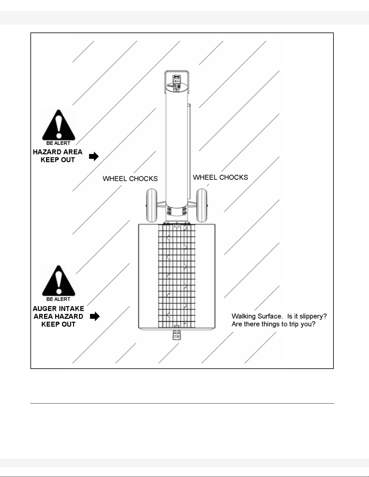
• Review the work safety area diagram before starting work.
IM2 R2 9
2. SAFETY FIRST WHEATHEART MANUFACTURING - TRANSFER AUGER
2.5. MAINTENANCE SAFETY 8”, 10”, & 13”
Figure 2.1 Work Area - Authorized Personnel Only
2.5. MAINTENANCE SAFETY
• Before applying pressure to a hydraulic system, make sure all components
are secure, hoses are in good condition, and couplings are tightly connected
and undamaged.
10 IM2 R2
WHEATHEART MANUFACTURING - TRANSFER AUGER 2. SAFETY FIRST
8”, 10”, & 13” 2.6. STORAGE SAFETY
• Relieve pressure from hydraulic circuit before servicing or disconnecting from
tractor.
• Place stands or blocks under the frame before working beneath the machine.
• After maintenance is complete, replace and secure all safety guards and
safety devices, and if applicable, service doors and cleanout covers.
• Remove all tools and unused parts from machine before operation.
• Remove buildup of grease, oil, and debris.
• Inspect all parts. Ensure parts are in good condition and installed properly.
Use only genuine Wheatheart Manufacturing replacement parts or equivalent.
Replacement parts must meet ASAE standards or serious injury may result. Use
of unauthorized parts will void the warranty. If in doubt, contact Wheatheart
Manufacturing or your Wheatheart Manufacturing dealer.
2.6. STORAGE SAFETY
• Store in an area away from human activity.
• Do not permit children to play on or around the stored machine.
2.7. HYDRAULIC SAFETY
• Always place all hydraulic controls in neutral and relieve system pressure
before disconnecting or working on hydraulic system.
• Keep all components in the hydraulic system tightly secured, clean and in
good condition.
• Replace any worn, cut, abraded, flattened, or crimped hoses.
• Do not attempt any makeshift repairs to the hydraulic fittings or hoses with
tape, clamps, or adhesive. The hydraulic system operates under extremely
high pressure; such repairs will fail suddenly and create a hazardous and
unsafe condition.
• Before moving a hydraulic cylinder, ensure that the attached component is
safely secured.
Hydraulic fluid can cause serious injury if it
penetrates the skin. If it does, see a doctor
immediately.
WARNING
• Relieve pressure before disconnecting
hydraulic line.
• Wear proper hand and eye protection and
use wood or cardboard, not hands, when
searching for leaks.
IM2 R2 11

2. SAFETY FIRST WHEATHEART MANUFACTURING - TRANSFER AUGER
2.8. ENGINE SAFETY 8”, 10”, & 13”
2.8. ENGINE SAFETY
• Be sure to stop engine and remove key or lock out power before inspecting or
servicing engine
• Refer to engine operation manual for further details.
2.9. TIRE SAFETY
• When replacing worn tires, ensure that they meet the original tire specifications. Never undersize the replacement tire.
• Let a qualified tire repair shop perform all required tire replacements.
• Ensure that the tires are inflated to the manufacturers's recommended pressure.
2.10. SAFETY DECALS
• Keep safety decals clean and legible at all times.
• Replace safety decals that are missing or have become illegible. See decal
location figures that follow.
• Replaced parts must display the same decal(s) as the original part.
• Safety decals are available from your distributor, dealer, or factory.
2.10.1. DECAL INSTALLATION
1. Decal area must be clean and dry, with a temperature above 50°F (10°C).
2. Decide on the exact position before you remove the backing paper.
3. Align the decal over the specified area and carefully press the small portion
with the exposed sticky backing in place.
4. Slowly peel back the remaining paper and carefully smooth the remaining
portion of the decal in place.
5. Small air pockets can be pierced with a pin and smoothed out using the sign
backing paper.
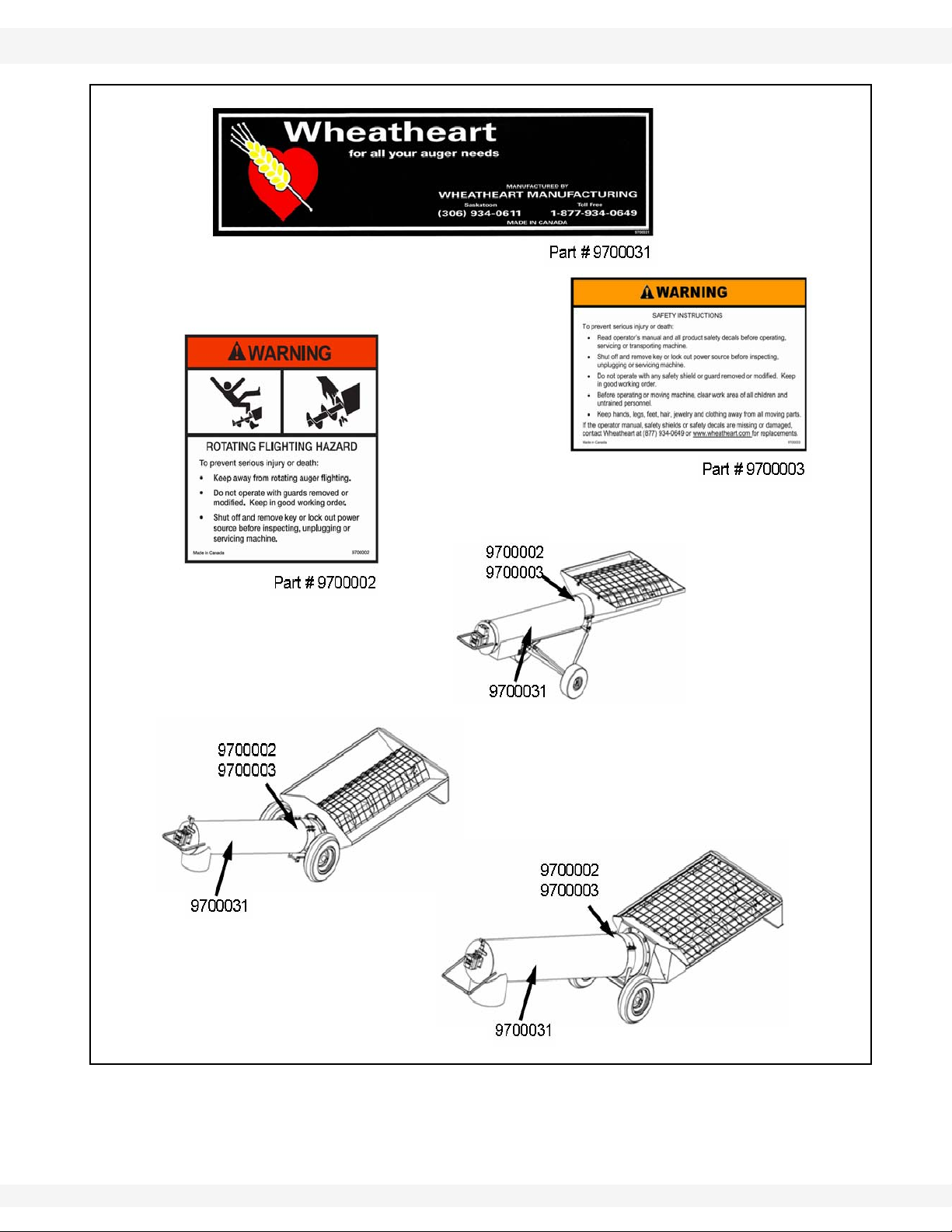
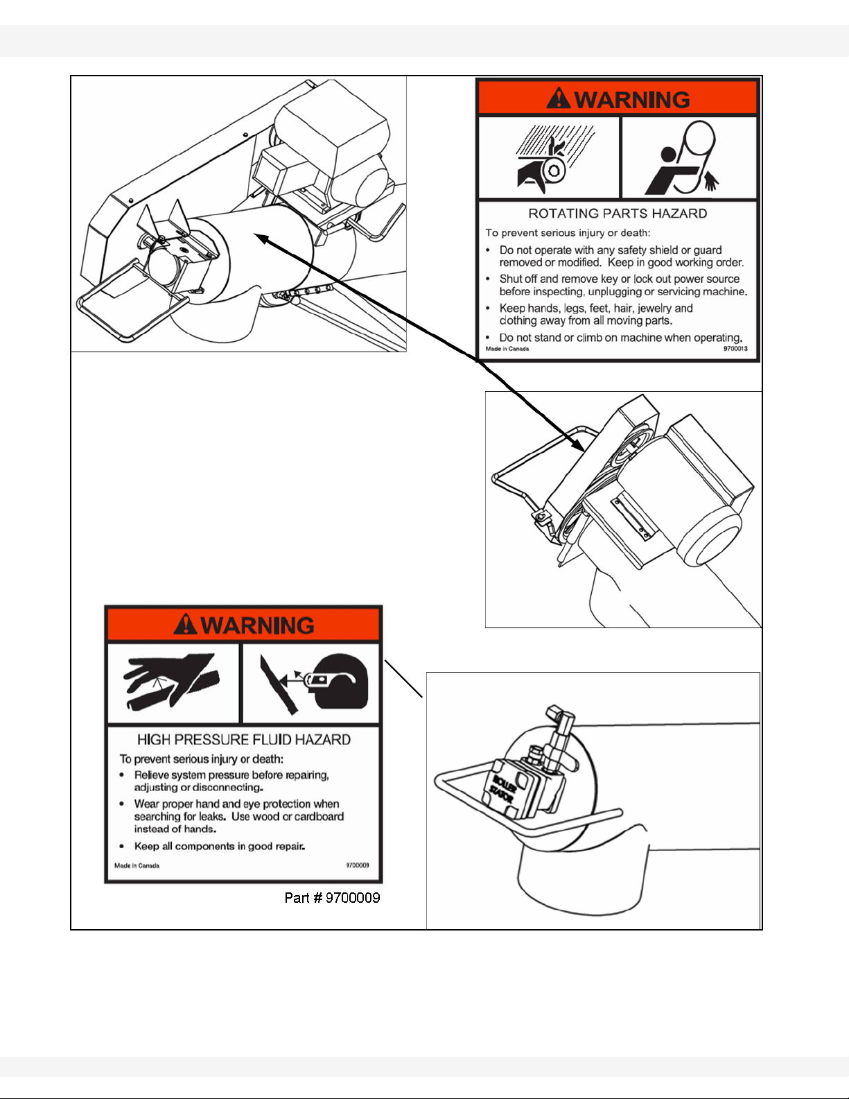
2.10.2. SAFETY DECAL LOCATIONS
Replicas of the safety decals that are attached to the equipment are shown in the
figure(s) that follow. Proper safety procedures require that you familiarize
yourself with the various safety decals and the areas or particular functions that
the decals apply to, as well as the safety precautions that must be taken to avoid
serious injury, death, or damage.
12 IM2 R2
WHEATHEART MANUFACTURING - TRANSFER AUGER 2. SAFETY FIRST
8”, 10”, & 13” 2.10. SAFETY DECALS
Figure 2.2 Safety Decals
IM2 R2 13
2. SAFETY FIRST WHEATHEART MANUFACTURING - TRANSFER AUGER
2.10. SAFETY DECALS 8”, 10”, & 13”
Figure 2.3 Safety Decals
14 IM2 R2
WHEATHEART MANUFACTURING - TRANSFER AUGER 3. ASSEMBLY
Warning: Before continuing, ensure you have read and understand the relevant information
in the safety section. Safety information is provided to help prevent serious injury, death, or
property damage.
8”, 10”, & 13” 3.1. GAS DRIVE TRANSFER ASSEMBLY
3.Assembly
Augers are available in various combinations. In most cases, the following
instructions will apply to all augers. Where the information varies, additional
instructions will be included, indicated by an arrow.
3.1. GAS DRIVE TRANSFER ASSEMBLY
Refer to Figure 3.1, 3.2, 3.3, and 3.4 for assembly of Transfer Augers with gas
drives.
Note: Belts and pulleys NOT provided. You must supply your own.
AUGER SIZE Description QTY.
8” B70 BELT 1
3” X 3/4” BORE PULLEY 1
10” B70 BELT 1
3-3/4” X 1” BORE PULLEY 1
1. Secure spout (1) on stands to aid in assembly.
2. Attach motor mount top and bottom clamps (2) to tube (1) 15" (38.1 cm) from
the spout (see Figure 3.1) using eight 5/16" x 1-1/4" bolts (3) and locknuts
(4). Use a level to ensure mount is parallel to the ground before tightening.
3. Position plate (5) on motor mount (2) using pin (6), 3/4" flat washer (7), and
hairpin (8) to secure in place.
4. Insert tightener pin (9) in mount and secure with 1/2" flat washer (10) and
hairpin (11).
5. Remove spout (1) from stands.
6. Couple upper and lower flighting together with a u-joint (15) and secure each
side with a 3/8" x 2-1/4" bolt (16) and locknut (17) (Figure 3.2 and 3.3).
Note: U-joint is pre-assembled on upper tube flighting.
7. Attach upper tube (1) to hopper bottom (19) with seven 7/16" x 1-1/4" bolts
(20), flat washers (21), and nuts (22).
Note: Use flat washers on both sides of hopper/tube.
8. Attach upper (23) and lower (24) support tubes to axle (25) by sliding over
axle shaft.
9. Mount each tire and rim (44) on axle and secure with cotter pin (46) and flat
washer (45).
10. Attach upper support tubes (23) to motor mount bottom clamp (2) with two
1/2" x 2" bolts (26) and locknuts (27).
IM2 R2 15

3. ASSEMBLY WHEATHEART MANUFACTURING - TRANSFER AUGER
3.1. GAS DRIVE TRANSFER ASSEMBLY 8”, 10”, & 13”
11. Install wheel frame clamp top and bottom (12) to lower end of tube (see
Figure 3.1) with four 5/16" x 1-1/2" bolts (13) and locknuts (14). Do not
tighten.
12. Attach lower support tubes (24) to wheel frame clamp (12) with two 1/2" x 11/2" bolts (28) and locknuts (29).
13. Adjust the position of the lower wheel frame clamp so that the back of the
hopper is elevated ~1/2" from the ground (see Figure 3.1). Tighten bolts and
nuts.
14. Install the gearbox (30) on the auger shaft and secure with a 3/8" x 2" (31)
bolt and locknut (32).
15. Mount transport handle (36) to the bottom of the gearbox (30) with 3/8" x
3/4" bolts (37) and lock washers (38).
16. Connect bottom bracket (33) to gearbox (30) with 3/8" x 3/4" bolts (34) and
lock washers (35).
17. Place two washers (50) on gearbox (30) and mount top bracket (33) and
guard back plate (51) on gearbox (30) with three 3/8" x 3/4" bolts (34,48) and
3/8" lock washers (49).
18. Insert 1/4” x 1-1/2” key (39) on exposed gearbox shaft (30), and mount pulley
(40) on gearbox shaft.
19. Insert 1/4” x 1-1/2” key (39) on motor shaft (41) and mount 3.5" pulley (42) on
shaft.
20. Rotate tightener pin (9) as far as it will freely turn so that the handle points in
the direction of the hopper.
21. Place the gas engine (41) on the motor mount (5), and using a level or
straight edge, align the ends of the gearbox (30) and motor (41) shafts.
22. Adjust the motor position so that the center of the shafts are approximately
23”–25"(58.4 cm - 63.5 cm) apart. Refer to Figure 3.4.
23. Use c-clamps or vice grips to temporarily secure the motor to the mount.
24. Install the B-70 belts (43). (NOT Provided). The belts should deflect 1/2" to 3/
4" when pushed on with a 5 lb force. If they do not deflect properly, remove
the clamps and belts, adjust the position of the motor, and re-align. Repeat
this step until the belt tension is adequate. Remove the c-clamps or vice grips
when finished.
25. Mark hole locations on the motor mount and remove the motor. Drill holes
through to match the size of the mounting bolts, and install motor using bolts
and locknuts.
Note: The holes could be die ground to form slots in case of belt slippage after initial
break-in. This will save time later if any adjustment is required.
26. Attach guard front cover (47) and end cover (52) to backplate (51) with six
self-tapping screws (53).
27. Affix decals as shown in “Safety Decals” on page 12.
Note: The final rpm for the auger should be between 500-600. Example: for 3200 rpm,
using a 3.5" motor pulley, 1:1.5 gearbox, 12.7" gearbox pulley, final rpm = 588.
16 IM2 R2

WHEATHEART MANUFACTURING - TRANSFER AUGER 3. ASSEMBLY
8”, 10”, & 13” 3.1. GAS DRIVE TRANSFER ASSEMBLY
Figure 3.1 Side View of Assembly
Figure 3.2
IM2 R2 17

3. ASSEMBLY WHEATHEART MANUFACTURING - TRANSFER AUGER
3.2. HYDRAULIC DRIVE TRANSFER ASSEMBLY 8”, 10”, & 13”
Figure 3.3
Figure 3.4
3.2. HYDRAULIC DRIVE TRANSFER ASSEMBLY
Refer to Figure 3.5 – 3.8 for assembly of Transfer Augers with hydraulic drive
kits.
1. Insert a 3/8” x 2” bolt (2) through the hydraulic motor shaft (1) and secure to
upper auger shaft with a 3/8” locknut (3).
2. Mount hydraulic motor (1) to upper auger tube using four 3/8” x 3/4” bolts (4).
Note: Install bolts through tube end plate from inside.
18 IM2 R2
8" MODEL:
1. Remove the plate protecting the top of the hydraulic motor and place #112 o-
rings into the recessions in the top of the hydraulic motor.

WHEATHEART MANUFACTURING - TRANSFER AUGER 3. ASSEMBLY
Figure 3.5 A
B
8”, 10”, & 13” 3.2. HYDRAULIC DRIVE TRANSFER ASSEMBLY
2. Install a control valve (9) onto the hydraulic motor using the 5/16” Allen head
bolts (10). Install hydraulic fittings into the control valve (see Figure 3.6).
8”, 10”, AND 13” MODELS:
1. Attach axle (12) to tube (11) with four 5/16" x 1-1/2" bolts (16) and locknuts
(17) (see Figure 3.5 A). Locate the axle band so that the hopper is 1/2" (1.27
cm) off the ground.
2. Install frame stiffeners (21) on axle (12) and secure with bolt (22) and locknut
(23).
3. Place wheels (18) on axle (12) and anchor each with a 3/4" washer (19) and
cotter pin (20).
4. Refer to Figure 3.5 B for the poly transfer frame assembly.
POLY MODEL
1. Remove the plate protecting the top of the hydraulic motor and place #112 orings into the recessions in the top of the hydraulic motor.
2. Install a control valve (9) onto the hydraulic motor using the 5/16” Allen head
bolts (10). Install hydraulic fittings into the control valve (see Figure
3.6).Connect upper end of tube support (25) to tube (24) with two 3/8" x 1-1/
4" bolts (29), 3/8" flat washers (31), and 3/8" locknuts (30). Refer to Figure
3.6.
3. Connect lower end of tube support (25) to tube (24) with tube clamp (26),
bolts (27), and locknuts (28).
IM2 R2 19

3. ASSEMBLY WHEATHEART MANUFACTURING - TRANSFER AUGER
Figure 3.6
Figure 3.7
3.2. HYDRAULIC DRIVE TRANSFER ASSEMBLY 8”, 10”, & 13”
4. Attach upper (33) and
lower (32) support
tubes to axle (34) by
sliding over axle shaft.
5. Mount tire and rim (35)
on axle (34) and secure
with cotter pin (37) and
3/4" flat washer (36).
6. Install upper support
tubes (33) to tube
support (25) with a
1/2" x 6" bolt (38), 1/2"
flat washer (40), and
1/2" locknut (39).
7. Install lower support tube (32) to tube support (25) with two
3/8" x 1-1/4" bolts (41), 3/8" flat washers (43), and 3/8" locknuts (42).
HYDRAULIC DOUBLE DRIVES (10")
1. Connect the long hydraulic hoses (1 and 2) to the hopper hydraulic motor
(11). Run these hoses (1 and 2) through the hopper guard (D). Refer to
Figure 3.8.
2. Open center hydraulics only: Place the ball valve (4) on the handle (9) of
the transfer auger . Connect hose (1) to part (5B) of the valve. Place the swivel
fittings (12,14) into the ports of the tube hydraulic motor (8). Connect hose (2)
to the swivel fitting (12) of the hydraulic motor (see Figure 3.8). Join the short
hydraulic hose (3) into the swivel fitting (14) of the hydraulic motor . Place the
other end of the short hose (3) into the port (5A) of the valve. Next, secure the
hoses (1 and 2) to the tube. (See Figure 3.8.)
3. For 10” and 13” closed center
hydraulics only: Install 1/2”
nipple (6), 1/2” ball valve (7),
and 1/2” elbow (8) on pressure
side, and 1/2” swivel (5) on
return side (see Figure 3.7).
20 IM2 R2
4. Closed center hydraulics only: Attach hydraulic line (13) to elbow. Connect
hose (2) to the swivel fitting (7) on the hydraulic motor (8). Secure hoses (1
and 2) to the tube. (See Figure 3.8.)

WHEATHEART MANUFACTURING - TRANSFER AUGER 3. ASSEMBLY
8”, 10”, & 13” 3.2. HYDRAULIC DRIVE TRANSFER ASSEMBLY
Figure 3.8
IM2 R2 21

3. ASSEMBLY WHEATHEART MANUFACTURING - TRANSFER AUGER
3.2. HYDRAULIC DRIVE TRANSFER ASSEMBLY 8”, 10”, & 13”
3.3. ELECTRIC DRIVE TRANSFER ASSEMBLY
Refer to Figure 3.9 and 3.10 for assembly of Transfer Augers with electric drive
kits.
Note: Belts and pulleys NOT provided. You must supply your own.
AUGER SIZE Description QTY.
10” B55 BELT 2
4.2” PULLEY 1
1. Install wheel frame clamp top and bottom (5) to tube (1) but don’t tighten,
(see Figure 3.9) and secure with four 5/16" x 1-1/2" bolts (6) and locknuts (7).
2. Attach u-joint to hopper auger.
3. Attach upper tube (1) to hopper bottom (2) with seven 7/16" x 1-1/4" bolts (8),
flat washers (9), and nuts (10). When installing bolts, also attach frame
brackets (11) to hopper as shown in Figure 3.9.
Note: Use flat washers on both sides of hopper/tube.
4. Attach upper (3) and lower (4) support tubes to axle (12) by sliding over axle
shaft.
5. Mount each tire and rim (13) on axle and secure with cotter pin (15) and flat
washer (14).
6. Install upper support tubes (3) to wheel frame clamp (13) with two 1/2" x
1-1/2" bolts (6) and 1/2" locknuts (7).
7. Install lower support tubes (4) to lower frame brackets (11) with two 1/2" x 1-
1/2" bolts (16) and 1/2" locknuts (17). Adjust tube clamp until hopper is off
ground ~1/2" (1.27 cm) and tighten.
8. Install 1/4” x 1-1/2” key (19) on electric motor shaft (20) and mount drive
pulley (21) on shaft.
Note: Drive pulley should be 3.75" - 4.25"; see Figure 3.10.
9. Install 1/4” x 1-1/2” key (25) on flighting shaft (26) and mount pulley (27) on
shaft.
10. Insert motor mount plate (28) with hex nuts (29) into head plate (24).
11. Place the electric motor (20) on the mount (28), and using a level or straight
edge, align the ends of the flighting shaft (26) and motor shaft (20).
12. Use c-clamps or vice grips to temporarily secure the motor to the mount.
13. Mark hole locations on the motor mount and remove the motor and clamps /
vice grips. Drill holes through to match the size of the mounting bolts, and
install motor using bolts and locknuts.
14. Install the belts (30) (NOT PROVIDED). The belts should deflect 1/2" to 3/4"
when pushed on with a 5 lb force. If they do not deflect properly , tighten or
loosen the hex nuts (29) on the mount plate until the belt tension is adequate.
15. Secure pulley guard (31) to transfer handle tabs (32) with two bolts (33) and
3/8” locknuts (34).
Important: Final rpm for the auger should be between 500-600. Example: for 1750 rpm,
using a 3.75" motor pulley, 12.7" auger pulley, final rpm = 517.
22 IM2 R2

WHEATHEART MANUFACTURING - TRANSFER AUGER 3. ASSEMBLY
8”, 10”, & 13” 3.2. HYDRAULIC DRIVE TRANSFER ASSEMBLY
Figure 3.9
Figure 3.10
IM2 R2 23

3. ASSEMBLY WHEATHEART MANUFACTURING - TRANSFER AUGER
3.2. HYDRAULIC DRIVE TRANSFER ASSEMBLY 8”, 10”, & 13”
24 IM2 R2

WHEATHEART MANUFACTURING - TRANSFER AUGER 4. TRANSPORT & PLACEMENT
Warning: Before continuing, ensure you have read and understand the relevant information
in the safety section. Safety information is provided to help prevent serious injury, death, or
property damage.
8”, 10”, & 13” 4.1. TRANSPORT
4.Transport & Placement
4.1. TRANSPORT
1. When moving the Transfer Auger from location to location, place the unit on
a transport vehicle and tie down securely. DO NOT tow behind a vehicle.
NOTICE
DO NOT tow transfer auger behind a vehicle. Tires are not
rated for road use.
4.2. PLACEMENT
When placing the auger, follow these guidelines:
• Ensure there is enough clearance from other equipment to move the machine
into its working position.
• Move the machine under the truck or storage facility.
• Place the auger on a firm, level surface.
• Chock the wheels before augering any products.
Note: The machine is almost evenly balanced. Pushing down a little on the discharge
end will raise the intake end off the ground and allow easy maneuvering.
IM2 R2 25

4. TRANSPORT & PLACEMENT WHEATHEART MANUFACTURING - TRANSFER AUGER
4.2. PLACEMENT 8”, 10”, & 13”
26 IM2 R2

WHEATHEART MANUFACTURING - TRANSFER AUGER 5. OPERATION
Warning: Before continuing, ensure you have read and understand the relevant information
in the safety section. Safety information is provided to help prevent serious injury, death, or
property damage.
8”, 10”, & 13” 5.1. OPERATOR CONTROLS
5.Operation
5.1. OPERATOR CONTROLS
The transfer auger controls are located as shown in Figure 5.1. Please refer to
engine manual for engine controls.
Figure 5.1
IM2 R2 27
Augers are available in various combinations. In most cases, the following
instructions will apply to all augers. Where the information varies, additional
instructions will be included, indicated by an arrow.

5. OPERATION WHEATHEART MANUFACTURING - TRANSFER AUGER
5.2. DRIVES & LOCKOUTS 8”, 10”, & 13”
5.2. DRIVES & LOCKOUTS
Correct operation of this unit requires pre-inspection of the drive system,
operator knowledge on how to shut down the system, and a general monitoring
of the system during operation.
GAS ENGINE
DRIVE SYSTEM
Before starting the engine, ensure that:
• The gas tank is properly closed.
• The belt release is disengaged.
• The area surrounding auge is properly ventilated.
• Pulley guards are in place and secure.
LOCKOUT
• Shut down and lock out power source.
• remove the spark plug wire or the spark plug.
ELECTRIC MOTOR
DRIVE SYSTEM
Before starting the motor, ensure that:
• The motor is properly grounded.
• All electrical connections/wiring should be performed by a licensed electrician.
• Pulley guards are in place and secure.
LOCKOUT
• The electric motor should be equipped with a main power disconnect switch
capable of being locked in the off position only. The switch should be in the
locked position during shutdown or wherever maintenance is performed on
the auger .
• If no disconnect switch, disconnect power source.
• If reset is required, disconnect all power before resetting motor.
HYDRAULIC MOTOR
DRIVE SYSTEM
Before starting the motor, ensure that:
• Hoses are not leaking and are free of cracks.
• Hose connections are free of dirt and debris.
LOCKOUT
• Shut down power source and disconnect hydraulic hoses from power source.
28 IM2 R2

WHEATHEART MANUFACTURING - TRANSFER AUGER 5. OPERATION
8”, 10”, & 13” 5.3. OPERATING PROCEDURES
WARNING
Hydraulic fluid can cause serious injury if it
penetrates the skin. If it does, see a doctor
immediately.
• Relieve pressure before disconnecting
hydraulic lin.
• Wear proper hand and eye protection and
use wood or cardboard, not hands, when
searching for leaks.
5.3. OPERATING PROCEDURES
5.3.1. BREAK-IN PERIOD
Your auger does not require an elaborate break-in. However, following a few
simple tips during the first 1000 bu of operation can add to the reliability and life
of your machine.
If any unusual noises or vibrations are encountered, determine the source, shut
the auger off, lock out the power source, and adjust. If unsure of the problem, or
the procedure to fix it, contact your local Wheatheart dealer.
PRE OPERATION CHECKLIST:
• Read the power source operation manual.
• Inspect motor mounting bolts for tightness.
• Check oil level in the gear box by removing the filler plug. Make sure the
gear box is half full (center cross shaft) and free of foreign objects.
• Inspect all belts for alignment, tightness, and abnormal wear. Adjust or
replace as required.
• Inspect components for damage and abnormal wear. Replace as
required.
• Check that safety decals are installed and legible. Apply new decals if
Please refer to “Maintenance Intervals” on page 34 for recommended service
intervals after the break-in period.
required.
• Check upper chain drive tension and alignment, apply or adjust grease.
5.3.2. OPERATION
The following items should be checked before operating the machine each time:
• Visually inspect the machine.
• Ensure that all guards are in place, and secure.
IM2 R2 29

5. OPERATION WHEATHEART MANUFACTURING - TRANSFER AUGER
5.3. OPERATING PROCEDURES 8”, 10”, & 13”
• Check that drive belts are not frayed or damaged, and that they are properly adjusted and aligned.
• Ensure auger wheels are chocked.
• See that the discharge spout and intake area are free of obstructions.
• Ensure that operators are aware of safety precautions.
NORMAL START-UP
1. Start the power source.
2. GAS/HYDRAULIC DRIVES: Increase the augering speed to achieve the
desired speed.
The flighting rpm on augers equipped with electric motors is not adjustable.
3. If everything is operating normally, start running grain through the auger.
Note: In cold weather conditions, the gas mount can be easily removed by removing
the pivot pin and hairpin and placed indoors to warm up. Once warmed, motor
and mount can be re-installed and started.
NOTICE
Engine must be idling before you engage the belts.
Engaging belts at high engine speed will result in premature
belt wear.
NOTICE
Foreign objects can damage the auger.
Remove any obstructions from the intake and discharge
areas before operating the unit.
DANGER
To prevent death or serious injury:
Keep away from rotating auger flighting.
Do not remove or modify auger flighting,
guards, doors, or covers. Keep in good
working order. Have replaced if damaged.
Do not operate auger without all guards,
doors and covers in place.
Never touch the auger flighting. Use a stick or
the tool to remove an obstruction or clean
out.
Shut off and lock power to adjust, service, or
clean.
30 IM2 R2

WHEATHEART MANUFACTURING - TRANSFER AUGER 5. OPERATION
8”, 10”, & 13” 5.3. OPERATING PROCEDURES
5.3.3. RESTARTING WITH A FULL TUBE
The tube may be filled with material if the machine is shut down inadvertently or
for an emergency. It is recommended that you restart with the following
procedure:
1. With the power source locked out, remove as much of the grain as possible
from the tube and intake.
2. GAS/HYDRAULIC DRIVE: Dis-engage belt and engage the power source
and run it at half speed. Re-engage belt. Then increase the engine speed to
achieve the desired augering speed.
3. ELECTRIC DRIVE: Start the electric motor and run to clear the full tube.
5.3.4. SHUTDOWN
NORMAL SHUTDOWN
1. Near the end of the load, reduce the feed of grain.
2. GAS/HYDRAULIC DRIVE: Decrease the auger speed.
3. Run the auger until the tube is empty.
4. Stop motor when auger is clear of grain.
5. Lock out power source.
.
NOTICE
Prolonged operation of an empty auger will cause
unnecessary wear.
EMERGENCY SHUTDOWN
Although it is recommended that the machine be emptied before stopping, in an
emergency situation:
1. Stop or shut down the power source immediately.
2. Stop the flow of material (if applicable).
3. Lock out power, and correct the emergency before resuming work.
WARNING
Lock out all power before attempting repairs
or removing obstructions.
IM2 R2 31

5. OPERATION WHEATHEART MANUFACTURING - TRANSFER AUGER
5.3. OPERATING PROCEDURES 8”, 10”, & 13”
5.3.5. CLEANOUT
1. Run the unit to clean out the majority of the grain.
2. Shut down and lock out the power source.
Note: Transfer can be tipped sideways to assist in fully cleaning unit on electric and
3. Clean grain from the auger and hopper, and dump it into a container.
hydraulic models only.
32 IM2 R2

WHEATHEART MANUFACTURING - TRANSFER AUGER 6. MAINTENANCE
Warning: Before continuing, ensure you have read and understand the relevant information
in the safety section. Safety information is provided to help prevent serious injury, death, or
property damage.
8”, 10”, & 13”
6.Maintenance
This unit has been designed and manufactured to meet the highest standards
while requiring minimal maintenance. Following a careful service and maintenance program will provide many years of trouble-free service.
To reduce the risk of injury or death to people using this equipment, follow basic
safety precautions.
When performing adjustments, service, or repairs:
• Always take safety into consideration and note Section 2.5.
• Use extra caution when cleaning and servicing augers because flighting
edges can become sharp.
• Follow proper procedures when mounting a tire on a rim, see Section 2.9.
6.0.1. FLUIDS & LUBRICANTS
ENGINE OIL
Refer to the engine operation manual for recommended oil usage.
GEAR OIL
Use SAE approved 90W or equivalent gear oil.
GREASE
Use SAE multi-purpose, high-temperature grease with extreme pressure (EP)
performance, or SAE multi-purpose lithium-based grease.
STORAGE & HANDLING
Always follow manufacturer’s guidelines for safe and effective storage and
handling of lubricants.
Your machine can operate at top efficiency only if clean lubricants are used. Use
clean containers to handle all lubricants. Store them in an area protected from
dust, moisture, and other contaminants.
IM2 R2 33

6. MAINTENANCE WHEATHEART MANUFACTURING - TRANSFER AUGER
6.1. MAINTENANCE INTERVALS 8”, 10”, & 13”
6.1. MAINTENANCE INTERVALS
Details of service are listed in Section 6.2.
Table 6.1
Time Period
Daily
(8000 BU)
Periodically
(40,000 BU)
Annually
(Before Storage)
Annually
(After Storage)
Visually inspect the unit.
Check engine oil level.
Check air filter.
Service belts.
Grease machine.
Check gearbox oil level (gas models).
Clean machine.
Service engine (gas & electric models).
Change gearbox oil.
6.2. MAINTENANCE PROCEDURES
6.2.1. VISUAL INSPECTION
Before beginning the visual inspection, chock auger wheels and ensure that all
operators are aware of safety precautions.
When inspecting:
• Ensure all guards are in place, and in good working order.
• Examine the auger for damage or unusual wear.
• Inspect the machine for evidence of oil leaks.
• Examine hydraulic hoses and fittings for leaks and cracks.
• Be sure all safety decals are in place and are legible.
• ELECTRIC DRIVE: Check that drive belts are not frayed or damaged.
Ensure they are properly adjusted and aligned.
• Check that the discharge spout and intake area are free of obstructions.
• Ensure that intake housing fasteners are properly secured.
34 IM2 R2
• Examine all flighting for damage or unusual wear.

WHEATHEART MANUFACTURING - TRANSFER AUGER 6. MAINTENANCE
8”, 10”, & 13” 6.2. MAINTENANCE PROCEDURES
• Inspect auger shaft bushing for unusual wear or discoloration.
Orientation of bushing will vary depending on model.
• Examine tires for gashes, uneven wear, or loss of air pressure.
Figure 6.1
IM2 R2 35

6. MAINTENANCE WHEATHEART MANUFACTURING - TRANSFER AUGER
6.2. MAINTENANCE PROCEDURES 8”, 10”, & 13”
6.2.2. GREASE MACHINE
Important: Original equipment bearings used by Wheatheart are sealed units and will not
accept grease.
1. Lock out all power.
2. Grease points on the machine are shown by arrows in Figure 6.2.
3. Use the grease recommended in Section 6.0.1.
4. Wipe grease fitting with a clean cloth before greasing to avoid injecting dirt
and grit.
5. If a fitting will not take grease, remove and clean thoroughly. Also clean
lubricant passageway. Replace fitting if necessary.
6. Replace and repair broken fittings immediately.
Figure 6.2
6.2.3. CLEAN MACHINE
1. Lock out all power.
2. Clean out excess grain from auger tube and intake.
3. Make sure nothing is obstructing the auger intake so water can run out.
4. Wash the tube with a water hose or pressure washer until all dirt, mud, debris,
or residue is washed from the auger.
5. Provide sufficient time for the water to drain from the auger.
36 IM2 R2

WHEATHEART MANUFACTURING - TRANSFER AUGER 6. MAINTENANCE
Figure 6.3
8”, 10”, & 13” 6.2. MAINTENANCE PROCEDURES
6.2.4. INSPECT HYDRAULIC HOSE & COUPLER
Using a piece of cardboard or wood, run it along the length of the hose and
around all fittings. Replace the hose or tighten/replace the fitting if a leak is
found.
WARNING
Hydraulic fluid can cause serious injury if it
penetrates the skin. If it does, see a doctor
immediately.
• Relieve pressure before disconnecting
hydraulic line.
• Wear proper hand and eye protection and
use wood or cardboard, not hands, when
searching for leaks.
6.2.5. SERVICE ENGINE
See engine operation manual for service requirements.
6.2.6. CHECK GEARBOX OIL LEVELS (GAS DRIVES)
1. Lock out all power.
2. Remove oil filler plug.
3. Make sure the gearbox is half full (center of cross shaft) and free of foreign
objects. Gearbox should be level when checking oil level.
6.2.7. CHANGING GEARBOX OIL (GAS DRIVES)
See Figure 6.3.
1. Remove guards and gearbox
from auger .
2. Place a pan under the drain
plug.
3. Use a wrench and remove the
drain plug.
4. Loosen the filler plug so air can
enter the gearbox and the oil will
drain freely.
5. Allow the oil to drain completely.
6. Replace the drain plug.
7. Add oil until the gearbox is half
full (center of cross shaft) and replace filler plug. Gearbox should be level
when checking or refilling. DO NOT OVERFILL.
8. Reinstall gearbox and guards.
IM2 R2 37
6. MAINTENANCE WHEATHEART MANUFACTURING - TRANSFER AUGER
Figure 6.4
MOVE CLAMP TO:
Figure 6.5
6.2. MAINTENANCE PROCEDURES 8”, 10”, & 13”
6.2.8. REPLACING BELTS (GAS & ELECTRIC DRIVES)
1. Lock out all power.
2. Remove guard to allow access to belts.
3. Disengage motor mount handle (gas only) and remove belts.
4. The new auger belts can now be put in place.
5. Follow procedure below for tightening belts.
6. Re-attach guards.
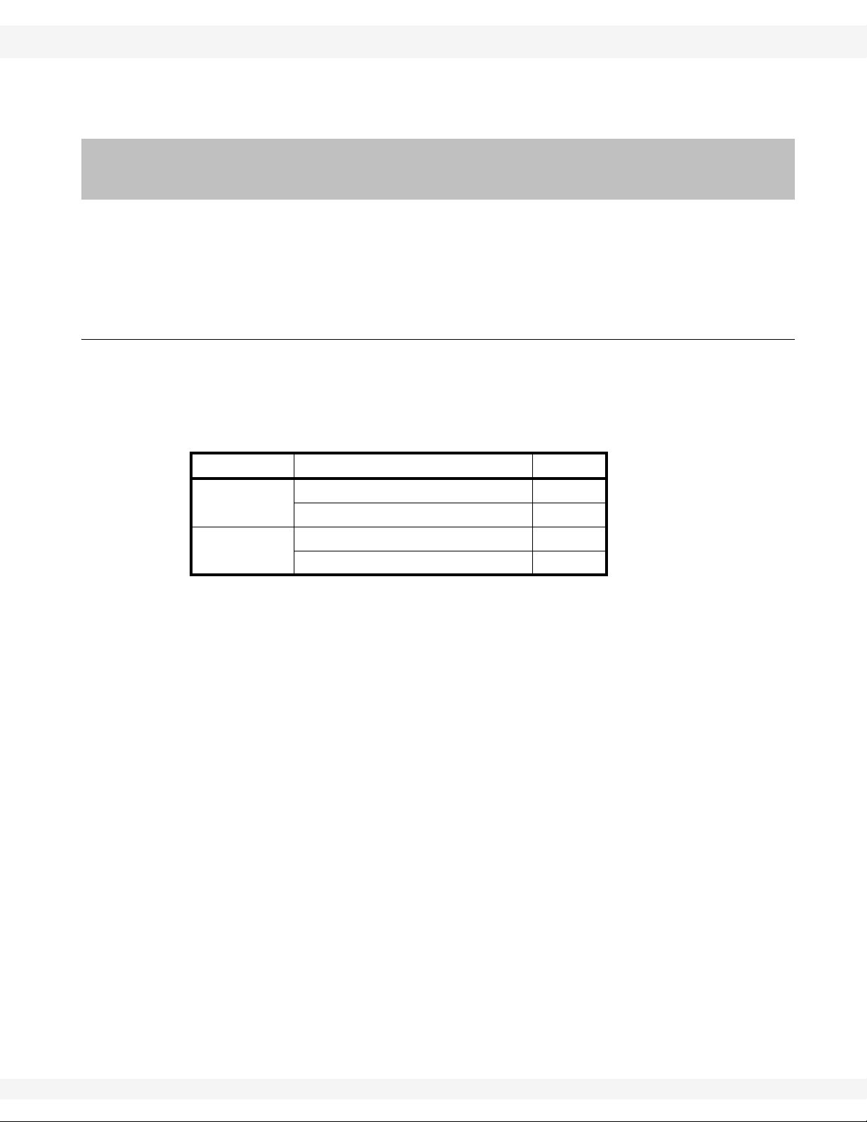
6.2.9. TIGHTENING BELTS (GAS & ELECTRIC DRIVES)
ELECTRIC DRIVES:
• If the drive belts are slipping, the belt should be
tightened by turning the
adjustment nuts clockwise
(see Figure 6.4) until the
belt is tight enough so that
it does not slip.
• If the drive belts have been
over-tightened, the belts
will wear quickly and extra
stress will be placed on the
pulleys. In this case, the
belt tension should be
lessened by turning the
adjustment nuts counterclockwise (see Figure 6.4).
38 IM2 R2
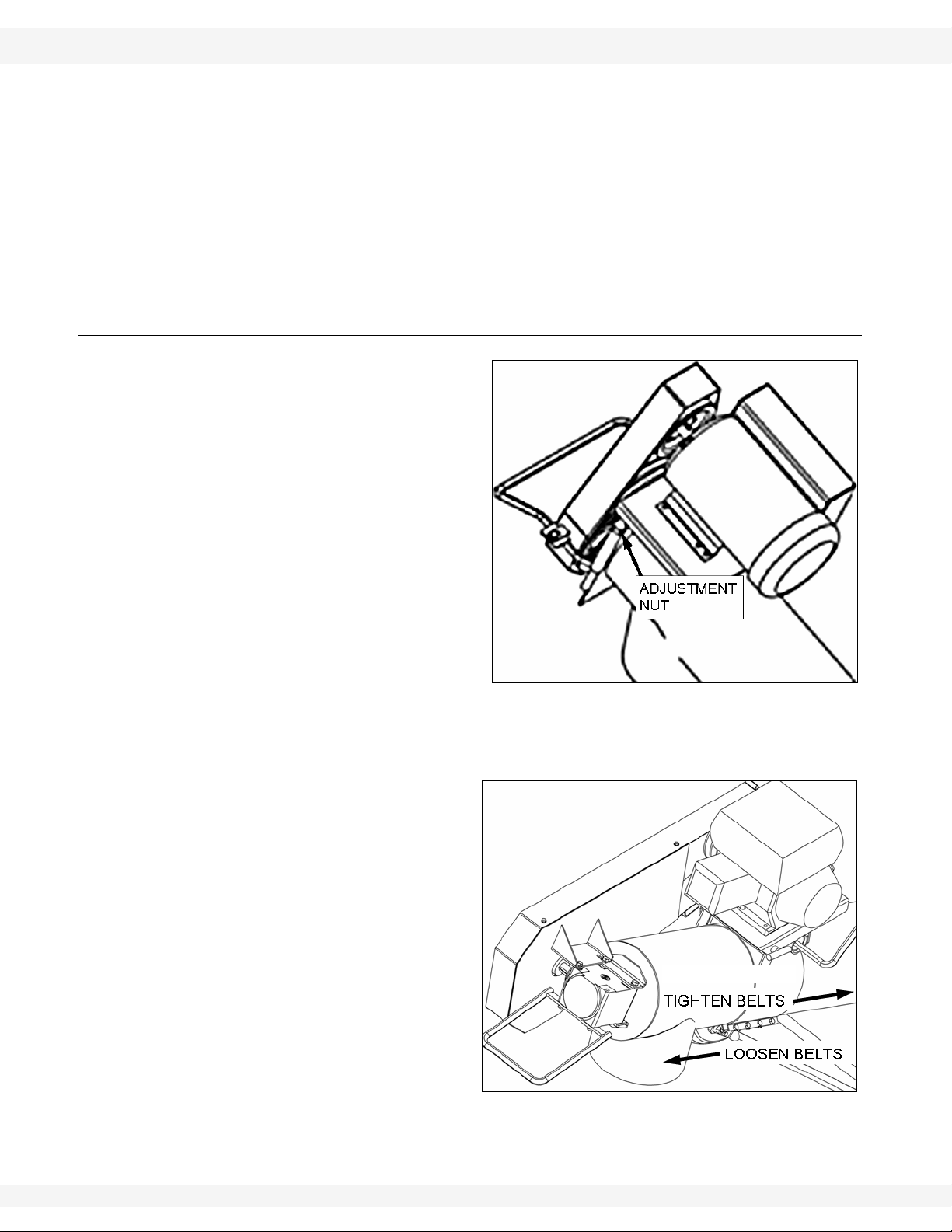
GAS DRIVES:
• If the drive belts are slipping, the belts should be
tightened. To tighten the
belts, loosen the overcenter handle, motor
mount clamp, and wheel
frame clamp. Slide each
clamp toward the hopper
approximately 1/2" and
tighten nuts (see Figure
6.5). Test belt to ensure it
no longer slips, repeat if
necessary.
• If the drive belts are too
tight, the belts should be
loosened. To loosen the

WHEATHEART MANUFACTURING - TRANSFER AUGER 6. MAINTENANCE
8”, 10”, & 13” 6.2. MAINTENANCE PROCEDURES
belts, loosen the over-center handle, motor mount clamp, and wheel
frame clamp. Slide each clamp toward the spout approximately 1/2" and
tighten nuts (see Figure 6.5). Test belt to ensure it no longer slips, repeat if
necessary.
Note: Refer to “Assembly” on page 15 for further details if required.
IM2 R2 39

6. MAINTENANCE WHEATHEART MANUFACTURING - TRANSFER AUGER
6.2. MAINTENANCE PROCEDURES 8”, 10”, & 13”
40 IM2 R2

WHEATHEART MANUFACTURING - TRANSFER AUGER 7. STORAGE
Warning: Before continuing, ensure you have read and understand the relevant information
in the safety section. Safety information is provided to help prevent serious injury, death, or
property damage.
8”, 10”, & 13”
7.Storage
To ensure a long, trouble-free life, the following procedure should be followed
when preparing the unit for storage after the season’s use:
• Lock out all power.
• Store the machine on a level surface, free of debris, and in an area away
from human activity. Store in a dry place, or use a tightly secured tarp to
protect the equipment from the weather.
• Remove all residual material and clean the machine thoroughly.
• Inspect the unit at stress points for cracks.
• Repair or replace any worn or damaged components to prevent any
unnecessary downtime at the start of the next season.
• Touch up paint nicks and scratches to prevent rusting.
• Check hydraulic fittings, hoses, lines, couplers, and valves. Tighten any
loose fittings. Replace any hose that is badly cut, nicked, abraded, or is
separating from the crimped end of the fitting. Secure the hoses to the
machine.
• Inspect and tighten all fasteners; replace fasteners if required.
• Inspect the engine for any abnormal leaks, check the air filter and clean or
replace as necessary. Drain the gas from the carburetor and gas tank.
Check to see if there is sufficient oil in the crankcase.
• Support intake on blocks to eliminate prolonged contact with the ground.
• Lubricate all grease fittings.
• Cover motor/engine to protect from weather.
• Chock wheels.
• Check tire pressure.
IM2 R2 41

7. STORAGE WHEATHEART MANUFACTURING - TRANSFER AUGER
8”, 10”, & 13”
42 IM2 R2

WHEATHEART MANUFACTURING - TRANSFER AUGER 8. TROUBLESHOOTING
8”, 10”, & 13”
8.Troubleshooting
The following table lists the causes and solutions to some potential problems you
may encounter in operating your machine.
Table 8.1
PROBLEM CAUSED BY SOLUTION
• auger is plugged or obstructed • identify and remove obstruction
• drive belt is slipping • adjust the tension of the belt
• a bearing is seized • identify the bearing and replace
The auger does
not turn.
• a chain is broken • identify the chain and repair or
replace
• gearbox is seized • fix or replace the gearbox
The horizontal
auger will not
turn.
Auger is noisy.
Low material
augering rate.
• gearbox coupler bolt is broken or
• replace the bolt
missing
• center coupler bolt is broken or
• replace the bolt
missing
• obstruction in the auger • identify and remove obstruction
• auger shaft bolts are loose or
• tighten or replace bolts
damaged
• auger shaft is bent • repair or replace auger
• flighting is damaged
• worn bearing • repair or replace bearing
• low gear oil level (Gas/Electric
Models)
• inspect the gearbox, replace if
damaged or add oil if not damaged
• engine speed is too slow • increase rpm of the engine
• inadequate material flow from
• increase flow of material
truck or hopper
• flow into the auger intake is
• clear grating of obstructions
restricted
• material too wet or heavy • unloading rates are for dry grain
• flighting is worn • repair or replace as required
• belt slipping • identify the belt; adjust or replace
as required
IM2 R2 43

8. TROUBLESHOOTING WHEATHEART MANUFACTURING - TRANSFER AUGER
8”, 10”, & 13”
44 IM2 R2

WHEATHEART MANUFACTURING - TRANSFER AUGER 9. APPENDIX
8”, 10”, & 13” 9.1. BOLT TORQUE VALUES
9.Appendix
9.1. BOLT TORQUE VALUES
The tables shown below give correct torque values for various bolts and
capscrews. Tighten all bolts to the torque specified in the chart unless otherwise
noted. Check tightness of bolts periodically , using bolt torque chart as your guide.
Replace hardware with the same strength bolt.
Table 9.1 Imperial Bolt Torque
BOLT
DIAMETER
1/4" 8 6 12 9 17 12
5/16" 13 10 25 19 36 27
3/8" 27 20 45 33 63 45
7/16" 41 30 72 53 100 75
1/2" 61 45 110 80 155 115
9/16" 95 60 155 115 220 165
5/8" 128 95 215 160 305 220
3/4" 225 165 390 290 540 400
7/8" 230 170 570 420 880 650
1" 345 225 850 630 1320 970
(Nm) (lb-ft) (Nm) (lb-ft) (Nm) (lb-ft)
Figure 9.1 Pattern for Tightening Wheel Bolts
IM2 R2 45

9. APPENDIX WHEATHEART MANUFACTURING - TRANSFER AUGER
9.1. BOLT TORQUE VALUES 8”, 10”, & 13”
Table 9.2 Metric Bolt Torque
BOLT DIAMETER
M3 0.5 0.4 1.8 1.3
M4 3 2.2 4.5 3.3
M5 6 4 9 7
M6 10 7 15 11
M8 25 18 35 26
M10 50 37 70 52
M12 90 66 125 92
M14 140 103 200 148
M16 225 166 310 229
M20 435 321 610 450
M24 750 553 1050 774
(Nm) (lb-ft) (Nm) (lb-ft)
M30 1495 1103 2100 1550
M36 2600 1917 3675 2710
Torque figures indicated above are valid for non-greased or non-oiled threads
and head unless otherwise specified. Therefore, do not grease or oil bolts or
capscrews unless otherwise specified in this manual. When using locking
elements, increase torque values by 5%.
46 IM2 R2

WHEATHEART MANUFACTURING - TRANSFER AUGER 9. APPENDIX
8”, 10”, & 13” 9.1. BOLT TORQUE VALUES
9.2. SPECIFICATIONS
Important: Wheatheart Manufacturing reserves the right to change specifications without
notice.
Table 9.3
9” POLY 8” HYD 8” ELEC 8” GAS
Tube Size 9” (22.9 cm) 8” (20.3 cm) 8”(2 0.3 cm) 8” (20.3 cm)
CAPACITIES
Unloading Rate
DIMENSIONS
Hopper Size
Hopper Clearance
Overall Length
Discharge Clearance
TIRES
Type
Up to 5000 Bu/hr
3
(176m
/hr)
27” X 36”
(68.6 cm X 91.4 cm)
20”
(50.8 cm)
8’4”
(20.3 m)
20”
(50.8 cm)
Up to 3000
Bu/hr
3
(106m
/hr)
8”
Up to 3000
Bu/hr
3
(106m
/hr)
3’ X 4’
(91.4 cm X 121.9 cm)
12”
(30.5 cm)
10’
(3.05 m)
24”
(61.0 cm)
Up to 3000
Bu/hr
3
(106m
/hr)
Inflation Pressure 20 - 24 psi (137-165kPa)
WEIGHT
Total Weight
140lb
(63.8 kg)
235lb
(106.6 kg)
265lb
(120.2 kg)
300lb
(136.1 kg)
POWER REQUIREMENTS
Gas Engine 5.5 HP (max)
Electric Motor 3 HP (max)
Hydraulic Motor 4.6,1/2NPTF 4.6,1/2NPTF
PART SPECIFICATIONS
Motor Pulley Size 3-3/4 - 4-1/4” 3.5”
Driven Pulley Size 12.7” 12.7”
Gearbox Oil Capacity
1/2 Imp GAL.
(2.3L)
Belt Size B69 B69
Table 9.4
10” ELEC 10” GAS 10” DD 13” HYD
Tube Size 10” (25.4c m) 10” (25. 4 cm) 10” (25. 4 cm) 13” (33. 0 cm)
CAPACITIES
IM2 R2 47

9. APPENDIX WHEATHEART MANUFACTURING - TRANSFER AUGER
9.1. BOLT TORQUE VALUES 8”, 10”, & 13”
Table 9.4
Unloading Rate
Up to 6000
Bu/hr
3
(106m
/hr)
Up to 6000
Bu/hr
3
(106m
/hr)
Up to 6000
Bu/hr
3
(106m
/hr)
Up to 9000
Bu/hr
3
(317m
/hr)
DIMENSIONS
Hopper Size
Hopper Clearance
Overall Length
Discharge Clearance
(91.4 cm X 121.9 cm)
24”
(61.0 cm)
3’ X 4’
12”
(30.5 cm)
10’
(3.05 m)
30”
(76.2 cm)
TIRES
Type 8”
Inflation Pressure 20 - 24 psi (137-165kPa)
WEIGHT
Total Weight
305lb
(138.3 kg)
320lb
(145.1 kg)
285lb
(129.3 kg)
490lb
(222.3 kg)
POWER REQUIREMENTS
Gas Engine 9 HP (MAX)
Electric Motor 5 HP (MAX)
Hydraulic Motor 4.6,1/2NPTF 4.6,1/2NPTF
PART SPECIFICATIONS
Motor Pulley Size
3-3/4 - 4-1/4”
DBL
3-5” DBL
Drive Pulley Size 12.7” DBL 12.7” DBL
Gearbox Oil Capacity
1/2 Imp GAL.
(2.3L)
Belt Size B69 B69
48 IM2 R2

LIMITED WARRANTY
Wheatheart warrants to the buyer that the new machinery is free from defects in material and workmanship.
This warranty is only effective for any new machinery that has not been altered, changed, repaired, or
treated since its delivery to the buyer, other than by Wheatheart or its authorized dealers or employees, and does not apply to accessories, attachments, tools, or parts sold or operated with the new
machinery if they have not been manufactured by Wheatheart.
Wheatheart shall only be liable for defects in the material or workmanship attributed to faulty material
or bad workmanship that can be proved by the buyer, and specifically excludes liability for rep airs arising as a result of normal wear and tear of the new machinery or in any other manner whatsoever, and
without limiting the generality of the foregoing, excludes application or installation of parts not completed in accordance with Wheatheart operation manual, specifications, or printed instructions.
A Warranty Registration Form and Inspection Report must be completed at the time of delivery and
returned to Wheatheart Manufacturing within thirty (30) days.
Warranty Period
Private Farm Use One (1) year from date of purchase.
Commercial, Custom, or Rental Use Ninety (90) days from date of purchase.
Replacement Parts Ninety (90) days from date of replacement
Defective parts are subject to inspection by a Wheatheart representative prior to approval of a warranty claim. All returned parts must be sent to the factory, freight pre-paid, in order to qualify for warranty replacement. Repaired or replaced parts will be returned freight collect.
If these conditions are fulfilled, Wheatheart shall at its own cost and its own option either repair or
replace any defective parts provided that the buyer shall be responsible for all expenses incurred as a
result of repairs, labor , parts, transport ation, or any other work, unless Wheatheart has authorized such
expenses in advance. Normal wear and service items such as belts, hoses, flashing, etc. are excluded
from warranty.
The warranty shall not extend to any repairs, changes, alterations, or replacements made to the new
equipment other than by Wheatheart or its authorized dealers or employees.
This warranty extends only to the original owner of the new equipment.
This warranty is limited to the terms stated herein and is in lieu of any other warranties whether
expressed or implied, and without limiting the generality of the foregoing, excluded all warranties,
expressed or implied, or conditions whether statutory or otherwise as to quality and fitness for any purpose of the new equipment, Wheatheart disclaims all liability for incidental or consequential damages.
This machine is subject to design changes and Wheatheart shall not be required to retro-fit or
exchange items on previously sold units except at its own option.
WARRANTY VOID IF NOT REGISTERED

Wheatheart
Part of the Ag Growth International Inc. Group
P.O. Box 39
Rosenort, Manitoba, Canada R0G 1W0
Phone: (866) 467-7207 (Canada & USA)
Fax: (866) 768-4852
website: www.wheatheart.com
email: sales@wheatheart.com
© Ag Growth International Inc. 2013
Printed In Canada
 Loading...