

Read this manual before using product. Failure
SA FLEX AUGER
71’ - 111’
ASSEMBLY & OPERATION MANUAL
to follow instructions and safety precautions can
result in serious injury, death, or property
damage. Keep manual for future reference.
Part Number: 30651 R5
Revised: May/13

This product has been designed and constructed according to general engineering
standardsa. Other local regulations may apply and must be followed by the operator.
We strongly recommend that all personnel associated with this equipment be trained
in the correct operational and safety procedures required for this product. Periodic
reviews of this manual with all employees should be standard practice. For your
convenience, we include this sign-off sheet so you can record your periodic reviews.
Date Employee Signature Employer Signature
a. Standards include organizations such as the American Society of Agricultural and Biological Engineers,
American National Standards Institute, Canadian Standards Association, International Organization for
Standardization, and/or others.

WHEATHEART - SA FLEX AUGER
71’ - 111’
TABLE OF CONTENTS
1. Introduction.......................................................................................................................... 5
2. Safety .................................................................................................................................... 7
2.1. General Safety Information ...................................................................................... 7
2.2. Assembly Safety....................................................................................................... 8
2.3. Operation Safety ...................................................................................................... 8
2.4. PTO Safety............................................................................................................. 11
2.5. Hydraulic Safety..................................................................................................... 11
2.6. Transport and Placement Safety............................................................................ 12
2.7. Maintenance Safety................................................................................................ 13
2.8. Safety Decals......................................................................................................... 13
2.8.1. Decal Installation...................................................................................... 13
2.8.2. Safety Decal Locations............................................................................. 14
3. Assembly ............................................................................................................................ 21
3.1. Tubes & Flighting ................................................................................................... 21
3.2. Flex Frame Components........................................................................................ 26
3.3. Flex Auger Boot...................................................................................................... 27
3.4. Connecting Flex Tube to Flex Frame..................................................................... 29
3.5. Adjustable Towbar.................................................................................................. 30
3.6. Discharge Spout & Thrust Adjuster........................................................................ 31
3.7. Truss 71’–91’.......................................................................................................... 32
3.8. Truss 111’............................................................................................................... 35
3.8.1. Cable Trussing ......................................................................................... 37
3.9. Scissor Lift Frame (71’–91’) ................................................................................... 38
3.9.1. Scissor Frame Assembly.......................................................................... 38
3.9.2. Attaching to Tube ..................................................................................... 45
3.10. Transport Undercarriage (111’)............................................................................ 48
3.11. Lift Cables (111’).................................................................................................. 51
3.12. Lift Cylinder Hydraulic Hoses (111’)..................................................................... 52
3.13. Hydraulics (71’–91’).............................................................................................. 54
3.13.1. Cylinder Installation................................................................................ 54
3.13.2. Hydraulic Cylinder Plumbing .................................................................. 56
3.14. PTO (CV) Driveline............................................................................................... 57
3.15. Low Profile Hopper............................................................................................... 58
3.15.1. Steering Assembly.................................................................................. 60
3.15.2. Attaching Swing to Flex Auger ............................................................... 67
3.15.3. Hopper Lift Arm/Winch ........................................................................... 67
3.15.4. Placing Hopper into Transport Position.................................................. 70
3.16. Flex Auger Hydraulics.......................................................................................... 71
3.16.1. Open-to-Closed-Center Conversion....................................................... 75
3.17. Hitch Jack............................................................................................................. 76
3.18. Auger-to-Tractor Hookup...................................................................................... 76
3.18.1. PTO Driveline / Drawbar......................................................................... 76
3.18.2. Hydraulic Hose Couplers........................................................................ 78
30651 R5 3

WHEATHEART - SA FLEX AUGER
71’ - 111’
TABLE OF CONTENTS
4. Transport & Placement ...................................................................................................... 79
4.1. Transport Procedure............................................................................................... 79
4.2. Placement Procedure............................................................................................. 81
4.2.1. Axle Extension Procedure ........................................................................ 84
5. Operation ............................................................................................................................ 87
5.1. Pre-Operational Checklist....................................................................................... 87
5.2. Auger Drive & Lockout............................................................................................ 87
5.3. Operating Procedure.............................................................................................. 88
5.3.1. Start-Up & Break-In .................................................................................. 88
5.3.2. Operating with a Full Load........................................................................ 90
5.3.3. Shutdown.................................................................................................. 91
5.3.4. Lowering Auger......................................................................................... 92
6. Maintenance & Storage...................................................................................................... 95
6.1. General Maintenance Procedures.......................................................................... 95
6.2. Mechanical Drive System....................................................................................... 97
6.3. Storage................................................................................................................... 98
7. Troubleshooting ................................................................................................................. 99
8. Appendix........................................................................................................................... 103
8.1. Specifications ....................................................................................................... 103
8.2. Bolt Torque Values .............................................................................................. 104
8.3. Lift Cylinder Hydraulics (111’)............................................................................... 105
8.4. How to Charge the Lift System (111’ Only).......................................................... 105
8.4.1. Hydraulic Motor Notes............................................................................ 106
Limited Warranty................................................................................................................... 107
4 30651 R5
WHEATHEART - SA FLEX AUGER 1. INTRODUCTION
71’ - 111’
1.Introduction
Thank you for purchasing a Wheatheart grain auger. Before using, please read
this manual and understand the various features of the equipment and precautions for efficient and safe operation.
Keep this manual handy for frequent reference and to review with new
personnel. A sign-off form is supplied on the inside front cover to record your
safety reviews. Call your local distributor or dealer if you need assistance or
additional information.
This manual should be regarded as part of the equipment. Suppliers of both new
and second-hand equipment are advised to retain documentary evidence that
this manual was provided with the machine.
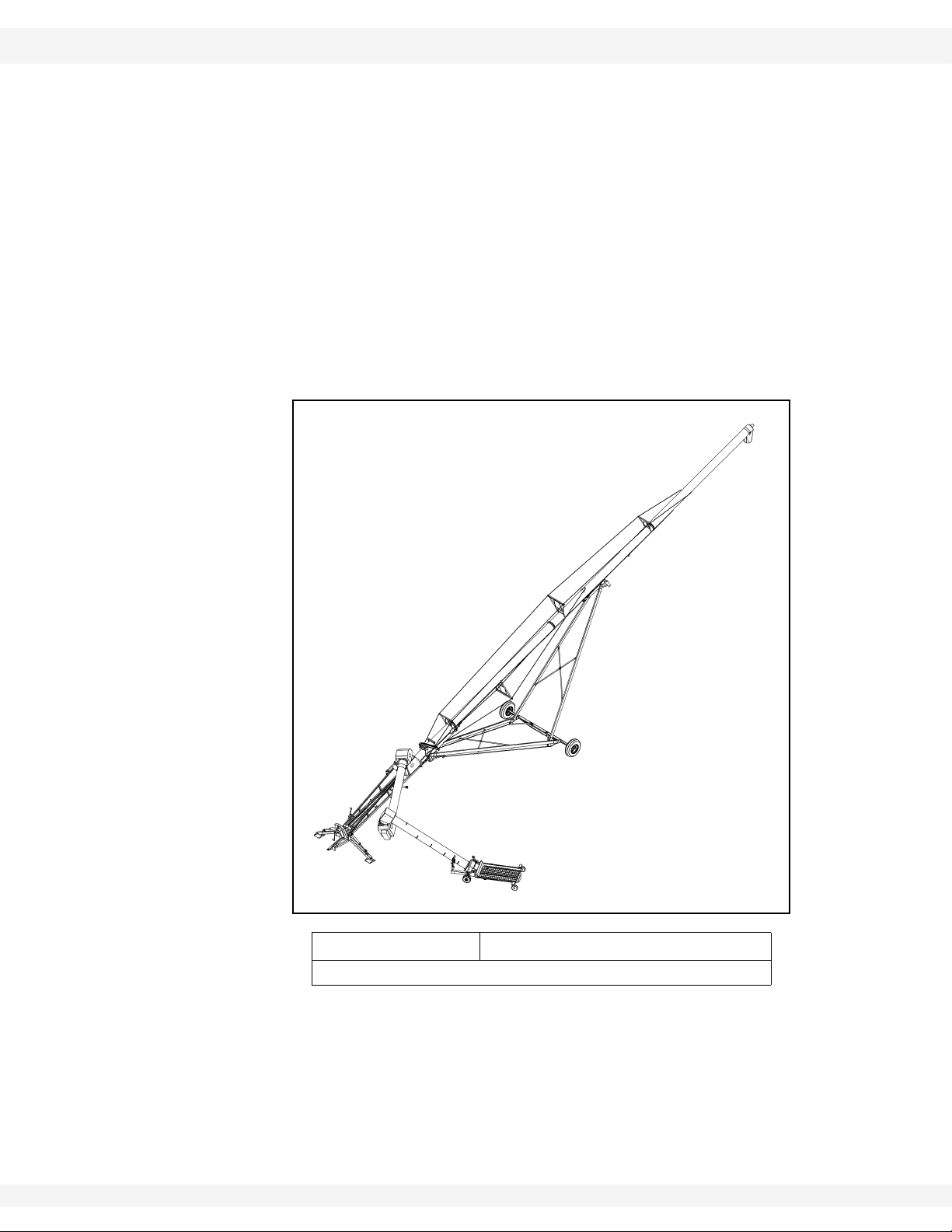
Serial Number:
*Serial number is located on the lower tube.
30651 R5 5

1. INTRODUCTION WHEATHEART - SA FLEX AUGER
71’ - 111’
6 30651 R5
WHEATHEART - SA FLEX AUGER 2. SAFETY
71’ - 111’ 2.1. GENERAL SAFETY INFORMATION
2.Safety
2.1. GENERAL SAFETY INFORMATION
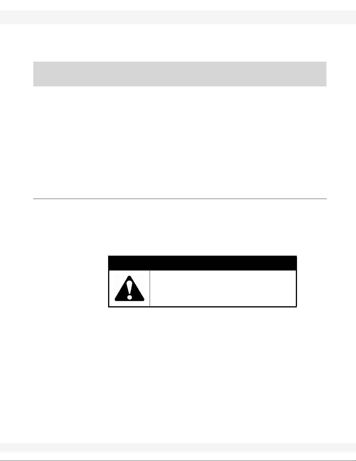
The Safety Alert symbol identifies important safety messages on the product and
in the manual. When you see this symbol, be alert to the possibility of personal
injury or death. Follow the instructions in the safety messages.
Why is SAFETY important?
• Accidents disable and kill.
• Accidents cost.
• Accidents can be avoided.
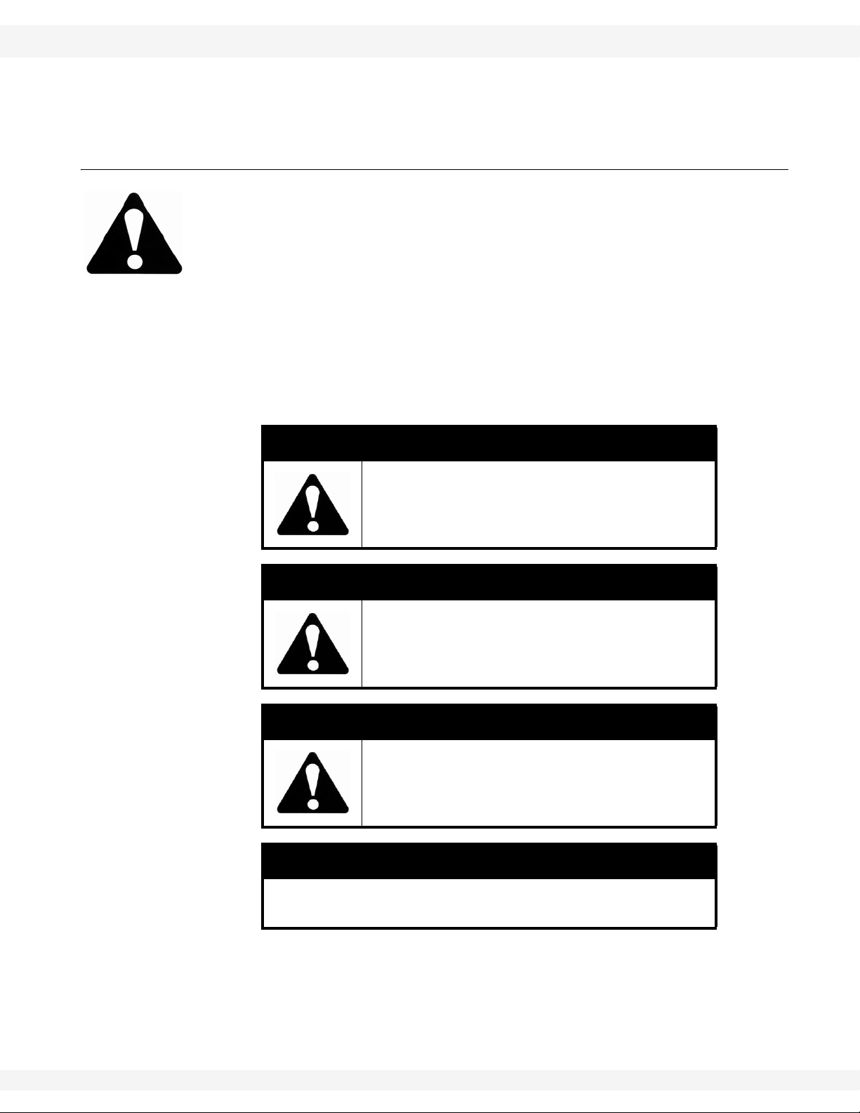
SIGNAL WORDS: Note the use of the signal words DANGER, WARNING,
CAUTION, and NOTICE with the safety messages. The appropriate signal word
for each message has been selected using the definitions below as a guideline.
DANGER
Indicates an imminently hazardous situation
that, if not avoided, will result in serious injury
or death.
WARNING
Indicates a hazardous situation that, if not
avoided, could result in serious injury or
death.
CAUTION
Indicates a hazardous situation that, if not
avoided, may result in minor or moderate
injury.
NOTICE
Indicates a potentially hazardous situation that, if not
avoided, may result in property damage.
30651 R5 7

2. SAFETY WHEATHEART - SA FLEX AUGER
2.2. ASSEMBLY SAFETY 71’ - 111’
YOU are responsible for the SAFE use and maintenance of your equipment.
YOU must ensure that you and anyone else who is going to work around the
equipment understands all procedures and related SAFETY information
contained in this manual.
Remember, YOU are the key to safety. Good safety practices not only protect
you, but also the people around you. Make these practices a working part of your
safety program.
Important: Below are general instructions that apply to all safety practices. Any instructions
specific to a certain safety practice (e.g., Operational Safety), can be found in the
appropriate section. Always read the complete instructional sections and not just
these safety summaries before doing anything with the equipment.
• It is the equipment owner, operator, and maintenance personnel's responsibility to read and understand ALL safety instructions, safety decals, and manuals and follow them when assembling, operating, or maintaining the
equipment. All accidents can be avoided.
• Equipment owners must give instructions and review the information initially
and annually with all personnel before allowing them to operate this product.
Untrained users/operators expose themselves and bystanders to possible
serious injury or death.
• Use this equipment for its intended purposes only.
• Do not modify the equipment in any way without written permission from the
manufacturer. Unauthorized modification may impair the function and/or
safety, and could affect the life of the equipment. Any unauthorized modification of the equipment voids the warranty.
• Do not allow any unauthorized person in the work area.
2.2. ASSEMBLY SAFETY
• Read and understand the instructions to get to know the sub-assemblies and
hardware that make up the equipment before preceding to assemble the
product.
• Do not take chances with safety. The components are large, heavy, and can
be hard to handle. Always use the proper tools, stands, jacks, and hoists for
the job.
• Always have two or more people assembling the equipment. Because of the
weight, do not attempt assembly alone.
2.3. OPERATION SAFETY
• Have another trained person nearby who can shut down the auger in case of
an accident. Always work with a second trained person around augers.
• Do not operate with any of the safety guards removed.
• Keep body, hair, and clothing away from moving p art s. Stay away from intake
during operation.
8 30651 R5

WHEATHEART - SA FLEX AUGER 2. SAFETY
71’ - 111’ 2.3. OPERATION SAFETY
• Inspect lift cable before using auger. Replace if frayed or damaged. Make
sure it is seated properly in the cable sheaves and that cable clamps are
secure.
• Operate auger on level ground free of debris. If ground is uneven, anchor the
auger to prevent tipping or upending.
• Augers are not insulated. Keep away from electrical lines. Electrocution can
occur without direct contact.
• Support the discharge end and/or anchor the intake end before operating to
prevent upending.
• Do not use auger as a hoist.
• Empty auger before raising or lowering.
• Lower auger at completion of operation or when not in use. Auger could drop
rapidly if the cable breaks or if the hydraulics fail (where applicable).
• Do not operate auger with the service or cleanout doors open or unlatched.
• Do not get on or beneath auger when raising or lowering intake hitch jack, or
when auger is supported by hitch jack.
• Do not operate auger with intake hopper in transport position. This will cause
damage to the u-joint.
30651 R5 9
2. SAFETY WHEATHEART - SA FLEX AUGER
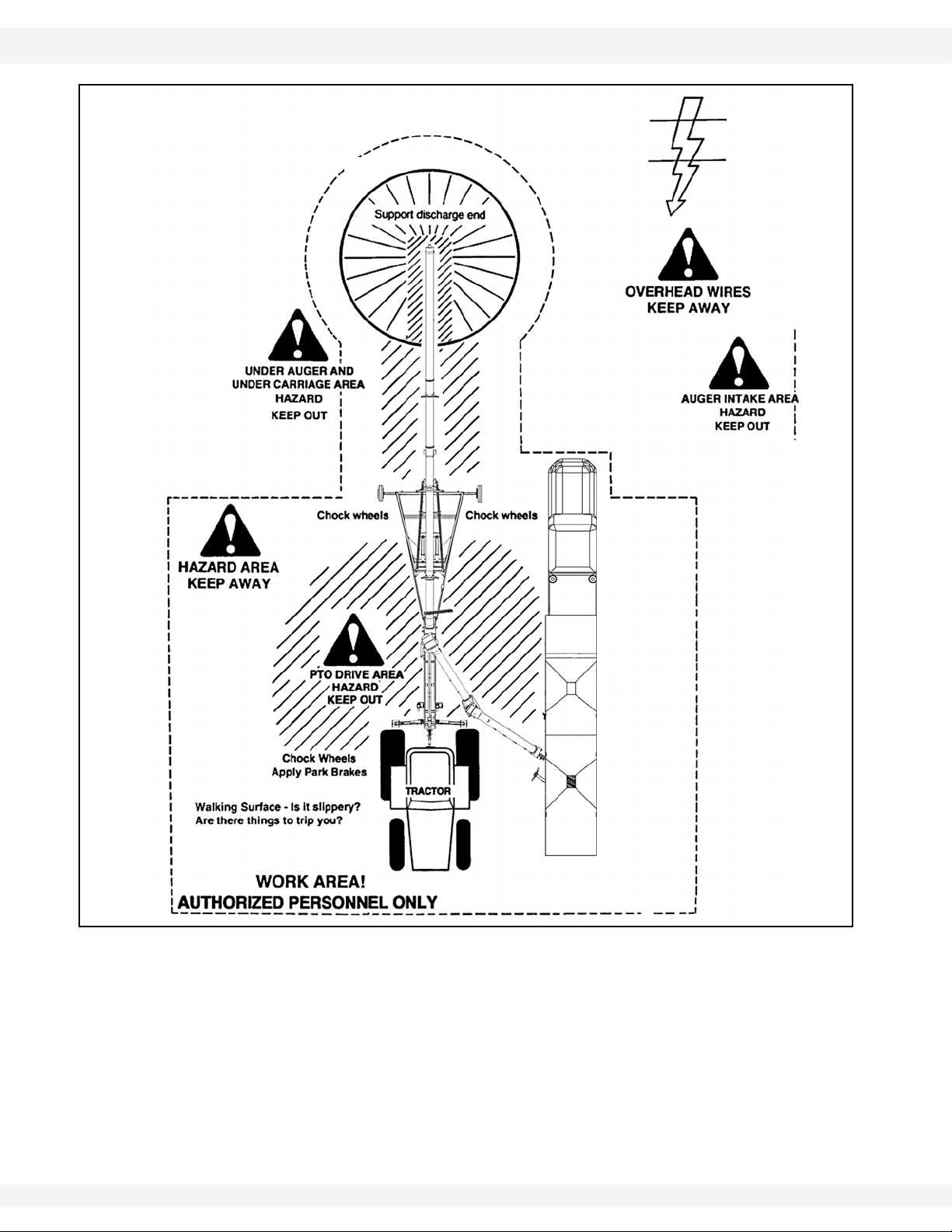
BIN
2.3. OPERATION SAFETY 71’ - 111’
Figure 2.1
10 30651 R5

WHEATHEART - SA FLEX AUGER 2. SAFETY
71’ - 111’ 2.4. PTO SAFETY
2.4. PTO SAFETY
• Never use a PTO driveline without a rotating shield in good working order.
• Ensure PTO driveline is securely attached at both ends before operating.
• Before starting tractor, turn power to PTO to the off position (where applicable).
• Keep body, hair, and clothing away from rotating PTO driveline.
• Ensure the PTO driveline shields turn freely on the PTO driveline.
• Do not exceed operating speed of 540 rpm.
• Keep u-joint angles small and equal. Do not exceed recommended operating
length for PTO driveline.
2.5. HYDRAULIC SAFETY
• Wear proper hand and face protection when searching for hydraulic leaks.
Escaping fluid under pressure can penetrate the skin, causing serious injury
like gangrene. In case of accident, see a doctor immediately.
• Fluid leaks in the hydraulic lift cylinders or hoses will allow the auger to lower
inadvertently. Repair all leaks and breaks immediately. Rupture could cause
damage and/or personal injury.
• A hydraulic lift is faster than a conventional hand crank—always clear area of
personnel before raising or lowering.
• Do not disconnect hydraulic couplers when hydraulic system is pressurized.
For the correct procedure, consult this manual or your tractor manual.
• Relieve pressure before unhooking hydraulic lines.
• Inspect hydraulic fittings and hoses for damage on a daily basis. Repair if
damaged.
• Ensure that the hydraulic line(s) is (are) properly connected and secure.
• Keep hydraulic line(s) away from moving parts.
• Clean connections before connecting to equipment.
30651 R5 11
OVERHEAD
WIRES!
KEEP AWAY
HAZARD
AREA!
KEEP
OUT
2. SAFETY WHEATHEART - SA FLEX AUGER
2.6. TRANSPORT AND PLACEMENT SAFETY 71’ - 111’
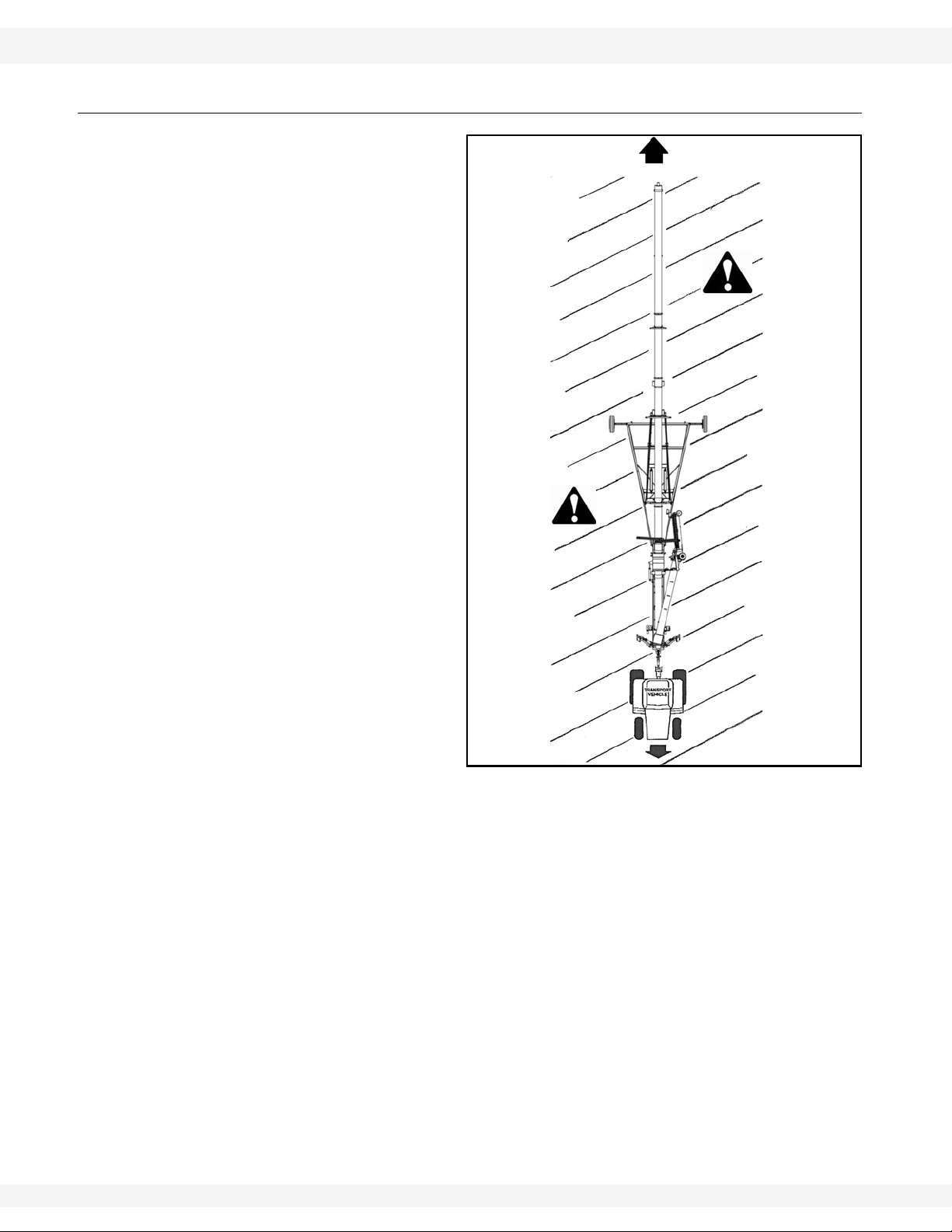
2.6. TRANSPORT AND PLACEMENT SAFETY
• Transport auger in full down
position with slight tension
on cable.
• Properly place hitch pin and
securely attach safety
chain. Use a type of hitch
pin that will not allow auger
to separate from towing
vehicle.
• Always attach an SMV
(slow moving vehicle) sign
before transporting auger .
Equip the auger with the
necessary lights for transportation where required by
law. Always use hazard
warning flashers on the
tractor/towing vehicle when
transporting, unless prohibited by law.
• Always travel at a safe
speed, never exceeding 15
mph (24 km/hr). Reduce
speed on rough surfaces
and be cautious when turning corners or meeting
traffic.
• Before raising/lowering/
moving the auger, make
sure the area around the auger is clear of obstructions and/or untrained personnel. Never allow anyone to stand on or beneath auger while transporting
or placing auger.
• Do not transport auger on slopes greater than 20°.
• Wheels must be free to move when raising or lowering auger.
• Never attempt to move auger manually. To do so will result in serious injury.
• Before moving auger, check for overhead obstructions and/or electrical wires.
Electrocution can occur without direct contact.
• Disconnect PTO driveline from tractor before moving auger or tractor, and
secure in transport saddle (where applicable).
• Raise intake feed hopper into transport position and lock hopper lift winch
before transporting or moving auger . Intake feed side of hopper must face
main auger when in transport position.
• Do not operate auger with intake hopper in transport position. This will cause
damage to the u-joint.
12 30651 R5

WHEATHEART - SA FLEX AUGER 2. SAFETY
71’ - 111’ 2.7. MAINTENANCE SAFETY
• Not intended for transport on public roads. If auger must be moved, check
local length and width regulations. Be careful when turning corners. Watch for
low overhead objects. Retract axles before transporting unit.
Important: The Flex Auger exceeds hitch weight capacity for most trucks and must be towed
with appropriate equipment. A tractor is recommended. Refer to the Specifications Section in the Appendix for details on the weight of this machine. Check
with your local dealer if you are unsure of your towing capacity.
2.7. MAINTENANCE SAFETY
• Shut down and lock out all power before attempting maintenance of any kind.
If applicable, disconnect PTO driveline from tractor or hydraulic hoses on
units with hydraulic drive hoppers.
• After maintenance is complete, replace and secure all safety guards and
safety devices, and if applicable, service doors and cleanout covers.
• Support auger tube before attempting maintenance on the undercarriage
assembly. Auger should be in full down position for maintenance.
• Use only genuine Wheatheart replacement parts or equivalent. Replacement
parts such as intake guards, pulley guards, PTO driveline shields, winches,
and lift cables must meet ASABE standards or serious injury may result. Use
of unauthorized parts will void warranty. If in doubt, contact Wheatheart or
your Wheatheart dealer.
• Do not modify any auger components without authorization from Wheatheart.
Modification can be dangerous and result in serious injuries.
2.8. SAFETY DECALS
• Keep safety decals clean and legible at all times.
• Replace safety decals that are missing or have become illegible. See decal
location figures that follow.
• Replaced parts must display the same decal(s) as the original part.
• Safety decals are available from your distributor, dealer, or factory.
2.8.1. Decal Installation
1. Decal area must be clean and dry, with a temperature above 50°F (10°C).
2. Decide on the exact position before you remove the backing paper.
3. Align the decal over the specified area and carefully press the small portion
with the exposed sticky backing in place.
4. Slowly peel back the remaining paper and carefully smooth the remaining
portion of the decal in place.
5. Small air pockets can be pierced with a pin and smoothed out using the sign
backing paper.
30651 R5 13
2. SAFETY WHEATHEART - SA FLEX AUGER
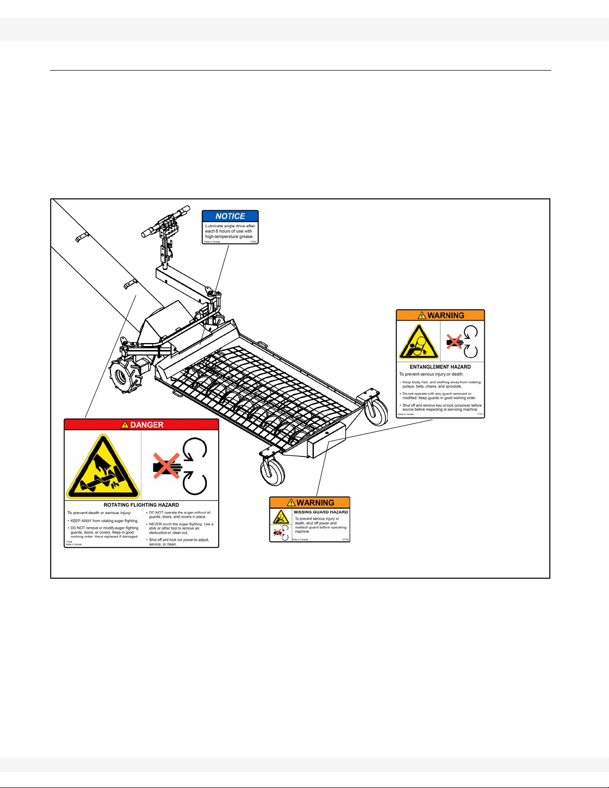
DECAL #17098
DECAL #17093
PLACED ON MACHINE
BEHIND GUARD
DECAL #27709
DECAL #17101
2.8. SAFETY DECALS 71’ - 111’
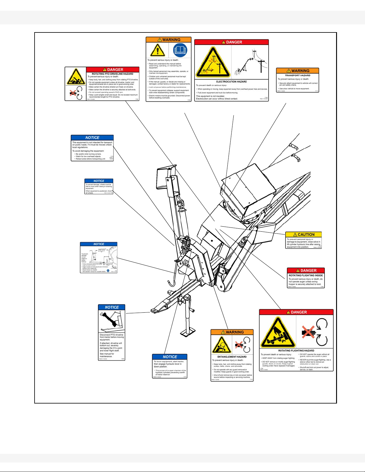
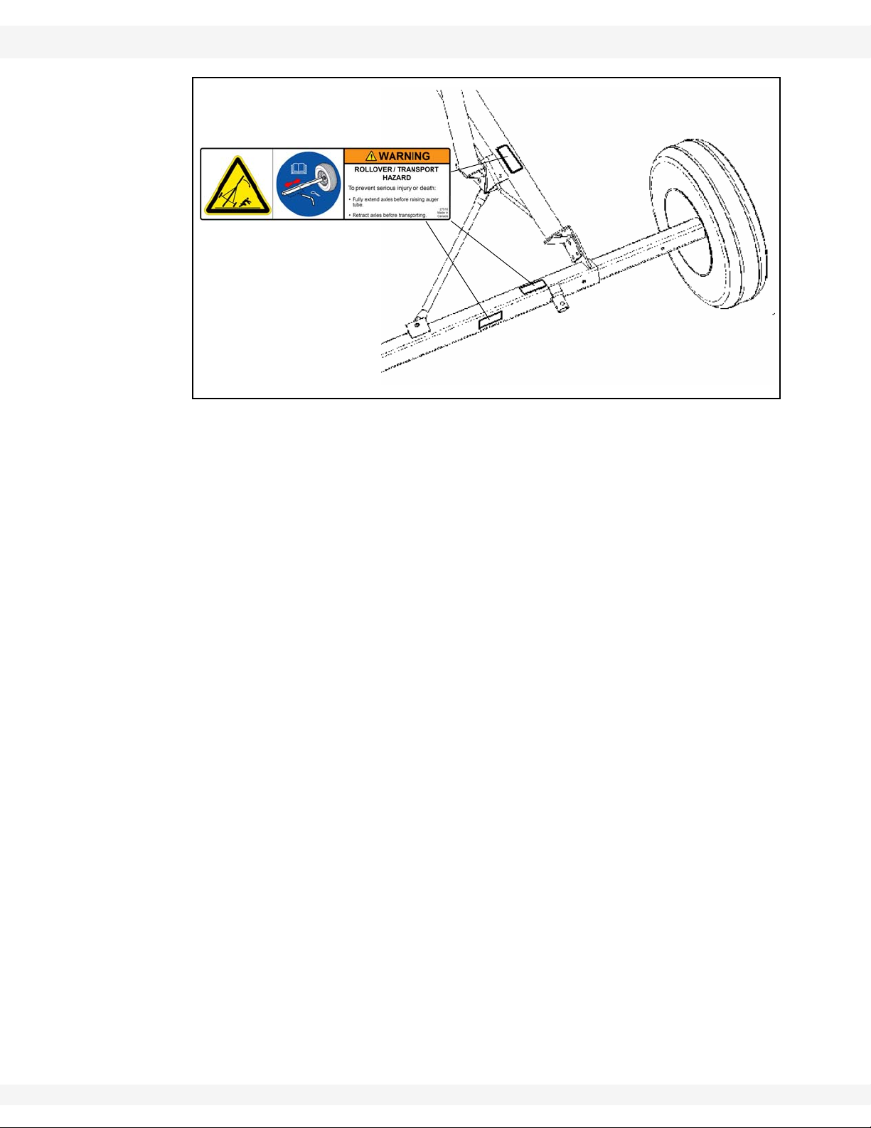
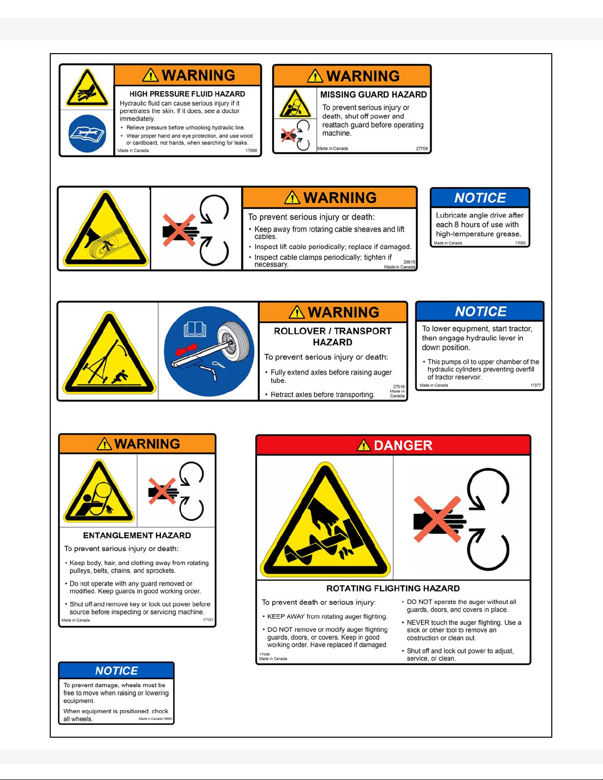
2.8.2. Safety Decal Locations
Replicas of the safety decals that are attached to the equipment are shown in the
figure(s) that follow. Proper safety procedures require that you familiarize
yourself with the various safety decals and the areas or particular functions that
the decals apply to, as well as the safety precautions that must be taken to avoid
serious injury, death, or damage.
*Wheatheart Manufacturing reserves the right to update safety decals without
notice. Safety decals may not be exactly as shown.
Figure 2.2
14 30651 R5
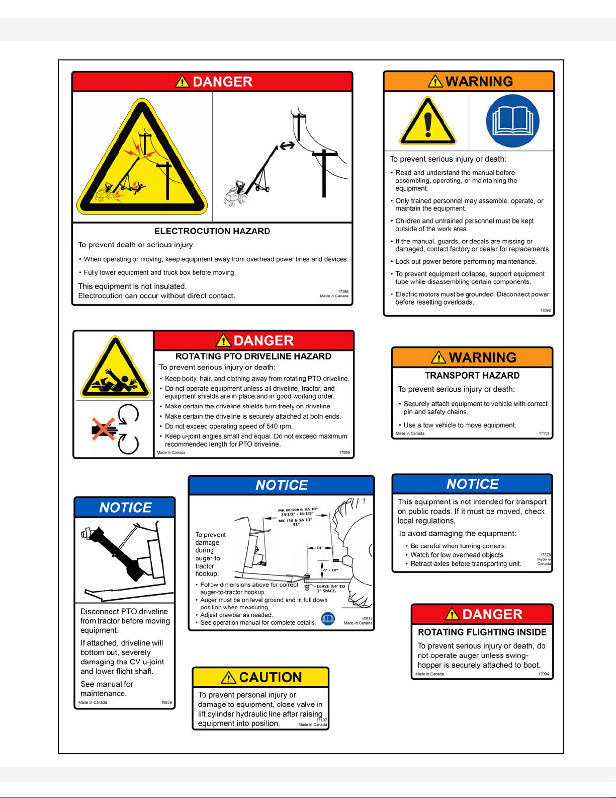
WHEATHEART - SA FLEX AUGER 2. SAFETY
DECAL #17096
DECAL #17398
DECAL #17099
DECAL #17113
DECAL #17378
DECAL #19960
DECAL #17377
SA 111 ONLY
DECAL #17531
DECAL #17107
DECAL #18859
DECAL # 17094
DECAL # 17098
DECAL #17101
71’ - 111’ 2.8. SAFETY DECALS
Figure 2.3
30651 R5 15
2. SAFETY WHEATHEART - SA FLEX AUGER
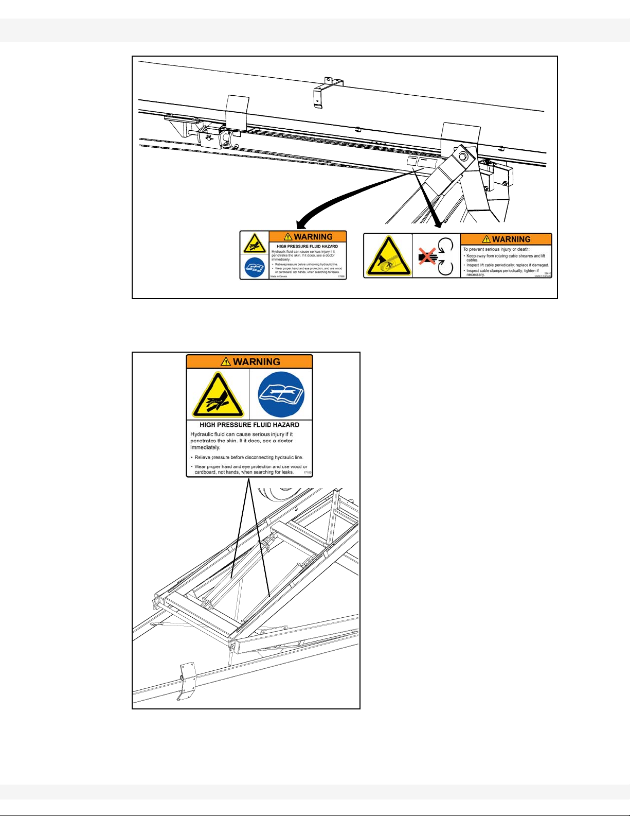
DECAL #17698
DECAL #28615
DECAL
#17100
2.8. SAFETY DECALS 71’ - 111’
Figure 2.4 SA Flex 111’
Figure 2.5 SA Flex 71’, 81’, 91’
16 30651 R5
WHEATHEART - SA FLEX AUGER 2. SAFETY
DECAL # 27516
NOTE: THE PLACEMENT OF THIS
DECAL VARIES DEPENDING ON
AUGER MODEL.
71’ - 111’ 2.8. SAFETY DECALS
Figure 2.6
Important: Please review the decals shown. If your auger does not have these decals, they
are available upon request. Please specify which decals you need.
30651 R5 17
2. SAFETY WHEATHEART - SA FLEX AUGER
DECAL # 27516
DECAL # 17698
DECAL # 28615
DECAL # 17093
DECAL # 17101
DECAL # 27709
DECAL # 17098
DECAL # 19960
DECAL # 17377
SA 111 ONLY
2.8. SAFETY DECALS 71’ - 111’
18 30651 R5
WHEATHEART - SA FLEX AUGER 2. SAFETY
DECAL # 17398
DECAL # 17099
DECAL # 17096
DECAL # 17113
DECAL # 17107
DECAL # 17094
DECAL # 18859
DECAL # 17378
DECAL # 17531
71’ - 111’ 2.8. SAFETY DECALS
30651 R5 19

2. SAFETY WHEATHEART - SA FLEX AUGER
2.8. SAFETY DECALS 71’ - 111’
20 30651 R5
WHEATHEART - SA FLEX AUGER 3. ASSEMBLY
WARNING Before continuing, ensure you have read and underst and the relevant information
in the safety section. Safety information is provided to help prevent serious injury, death, or
property damage.
71’ - 111’ 3.1. TUBES & FLIGHTING
3.Assembly
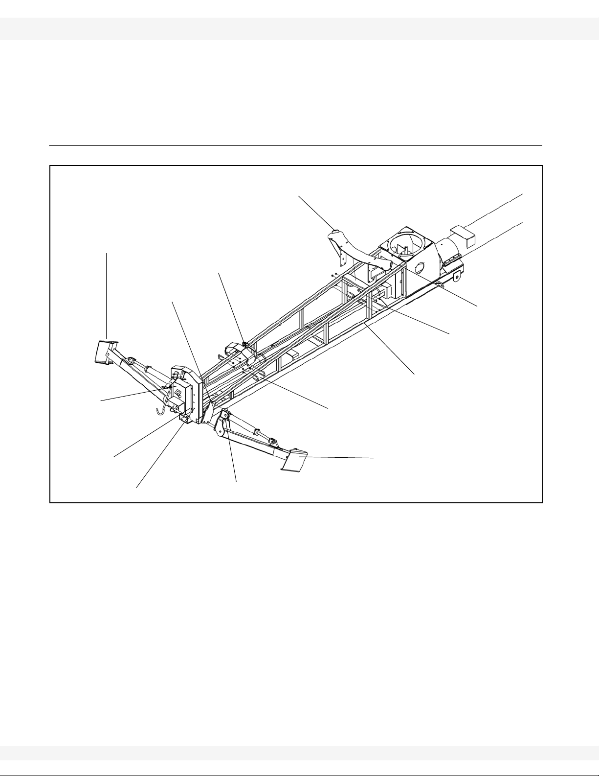
Before beginning assembly, familiarize yourself with all the sub-assemblies and
hardware for the auger. Have all parts on hand and arrange them for easy
access. Carry out assembly in a large, open area with a level surface.
Important: Always have 2 or more people assembling the equipment. Because of the
weight, do not attempt assembly alone.
Augers are available in various combinations. In most cases, the following
instructions will apply to all augers. Where the assembly information varies,
additional instructions will be included, indicated by an arrow.
Before assembling, please check with the customer if they prefer the swing
auger on the right or left side of the auger.
3.1. TUBES & FLIGHTING
Note: When assembling more than 2 sections, start from spout end and work towards
hopper.
1. Position tube sections. Align tube sections on a flat surface or on a series of
benches. See Figure 3.17 for the 71’, 81’ and 91’ and Figure 3.18 for the
111’.
After positioning tube sections, block them to
prevent rolling or dropping. Damage to
equipment or personal injury will result.
WARNING
• The 71’ has 4 tubes; from spout: 240” (6.10 m), 120” (3.05 m), 240” (6.10 m)
and 88” (2.24 m) long.
• The 81’ has 4 tubes; from spout: 240” (6.10 m), 240” (6.10 m), 240” (6.10 m)
and 88” (2.24 m) long.
• The 91’ has 5 tubes; from spout: 240” (6.10 m), 120” (3.05 m), 240” (6.10 m),
240” (6.10 m) and 88” (2.24 m) long.
30651 R5 21
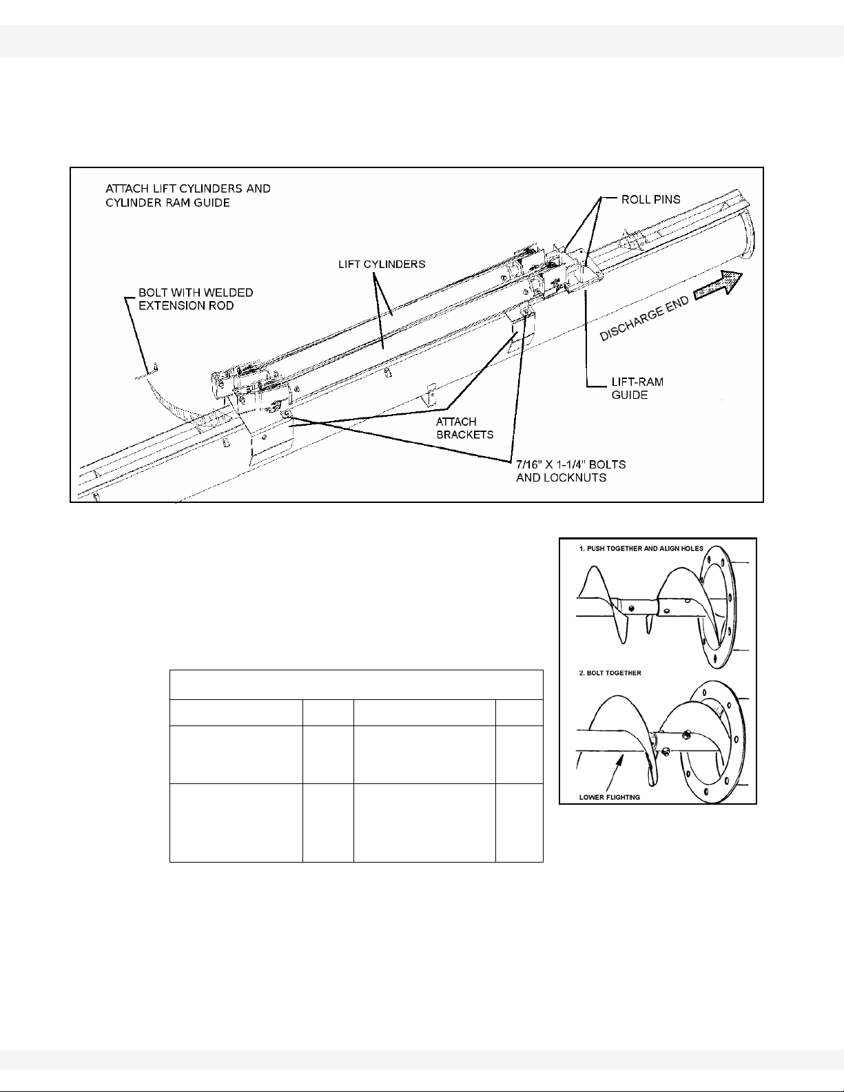
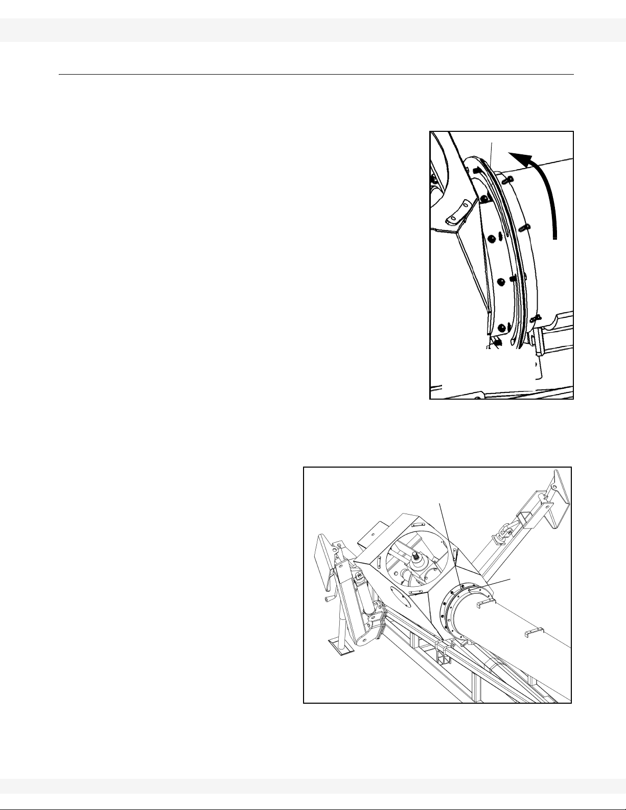
2. 1 11’ Only: To attach lift cylinders, rotate appropriate tube so track is facing
upward as shown in Figure 3.1.
a. Attach the lift cylinders to the attach brackets as shown in Figure 3.1 using
7/16” x1-1/4” bolts and locknuts.
• outside tabs—use regular bolts.
• inside tabs – use bolts with extension rods welded to head.
3. ASSEMBLY WHEATHEART - SA FLEX AUGER
Figure 3.2
3.1. TUBES & FLIGHTING 71’ - 111’
b. Slide the lift ram guide onto track on tube, then insert ram ends into
brackets on guide (Figure 3.1). Secure with two roll pins.
c. Return this tube section to the track down position.
Figure 3.1 111’ Only
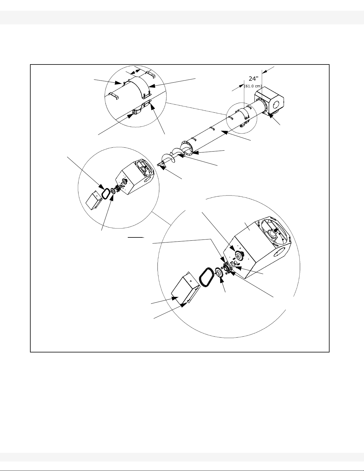
3. Slide lower flight shaft onto upper flight shaft
until flight ends butt together and flighting
spiral matches up (Figure 3.2). Secure with
hardware in Table 3.1. Repeat, if necessary,
for any remaining flight shafts.
Table 3.1
a
2
7/16” x 1-1/4” GR8
bolts and locknuts
1/2” x 1-3/4” GR8
1
bolts and locknuts
(2 top and 2
bottom)
12
4
Details for fastenings:
For Flighting Qty For Tubes Qty
5/8” x 4-1/2” GR8
bolts and locknuts
Track End (111’
Only)
5/8” x 2-3/4” GR8
bolt and locknut
a. Quantity listed is per tube connection.
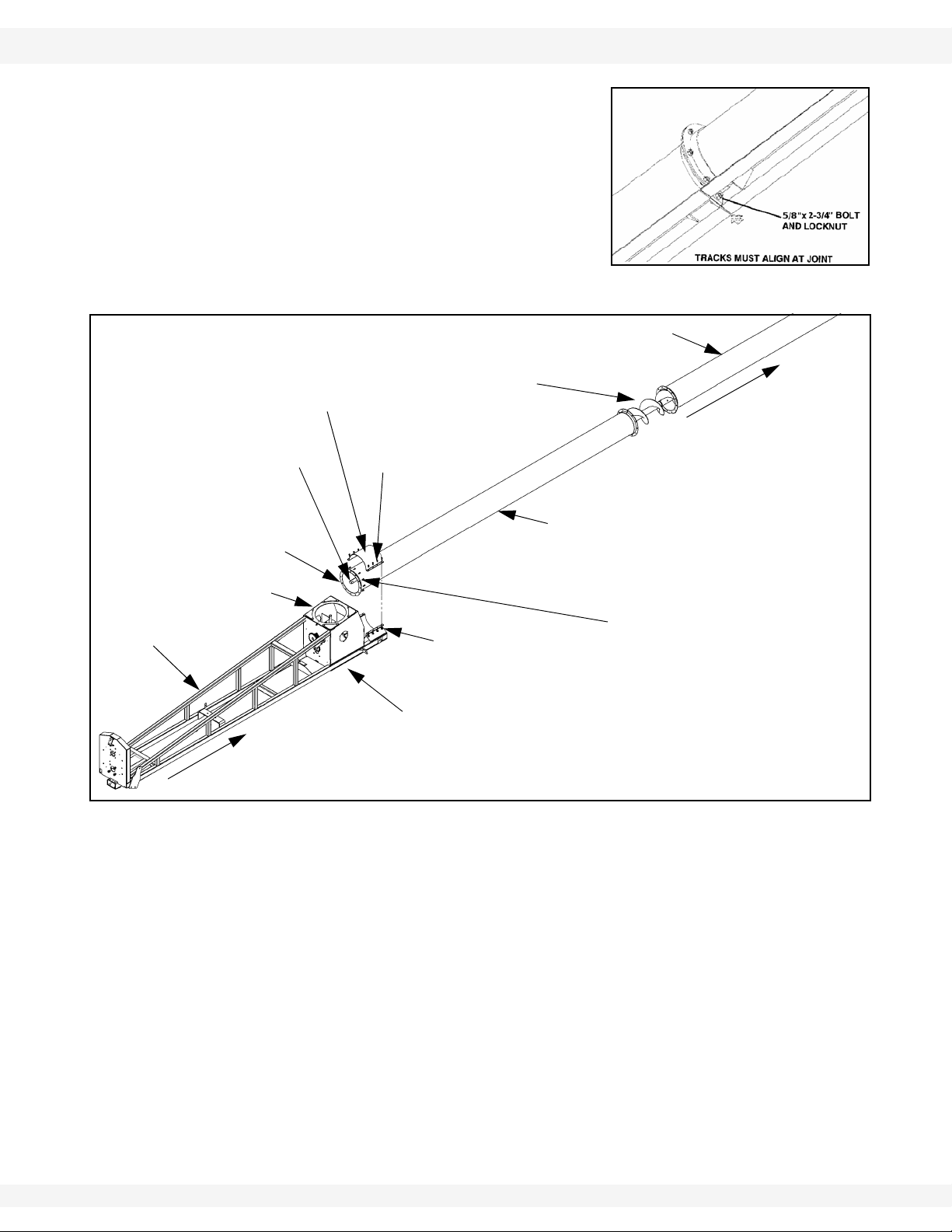
4. Slide tube sections together and secure. Make sure upper and lower track
ends are aligned (111’ only), and then tighten bolts. Secure with hardware in
Table 3.1.
Important: Do not connect lower auger tube to mid auger tube at this point! (Figure 3.4).
22 30651 R5
WHEATHEART - SA FLEX AUGER 3. ASSEMBLY
Figure 3.3 111’ only
ALIGN END OF TUBE WITH
END OF FLIGHT SHAFT.
LIFT FLEX FRAME UP
INTO PLACE.
SLIDE BACK SO TUBES
CONTACT ONE ANOTHER.
FLEX
FRAME
FLEX
FRAME
BOOT
5/8” X 2-1/4”
BOLTS
5/8” LOCKNUTS
LOWER
AUGER
TUBE
MID-AUGER
TUBE
FLIGHT SHAFT
END
AUGER FLIGHT
TUBE SUPPORT
CLAMP
S
P
O
U
T
7/16” X 1-1/4”
GR8 BOLTS
NOTE: T ubes may not be
exactly as illustrated.
71’ - 111’ 3.1. TUBES & FLIGHTING
5. 111’ only: Bolt the track ends together
(Figure 3.3).
6. Adjust lower auger tube out until it is flush
with the flight shaft end (see Figure 3.4).
7. Lift the flex frame up underneath the lower
tube and secure on benches.
8. Push the flex frame toward the spout to
slide the auger flight through the front of the
flex frame boot.
Figure 3.4
Important: Steps 11. to 19. must be completed in the order listed to prevent premature
Important: Grease zerk should be located on left side of bearing.
30651 R5 23
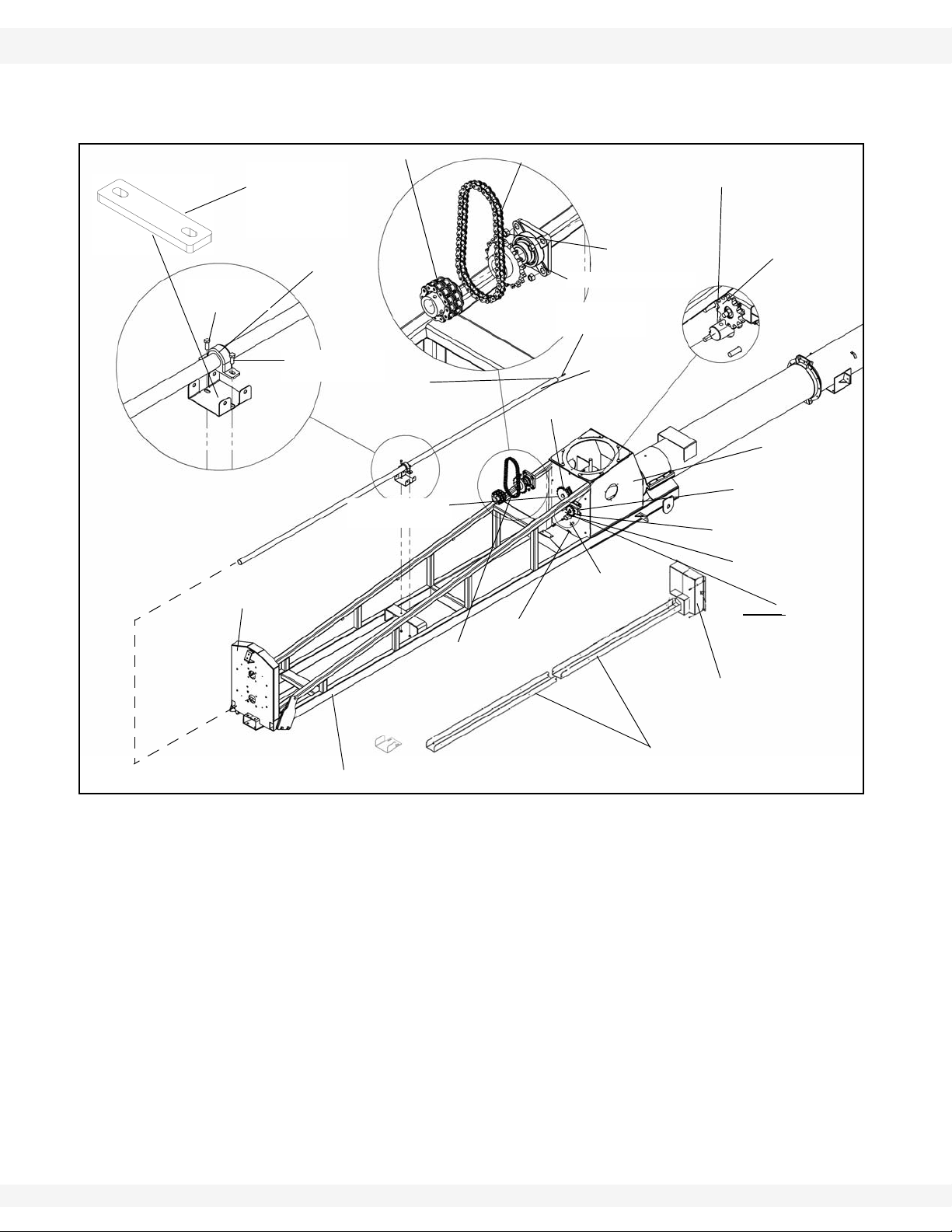
9. Connect flex frame assembly to lower auger tube flange with twelve 7/16” x
1-1/4” GR8 bolts and locknuts.
10. Secure tube support clamp to tube with eight 5/8” x 2-1/4” GR8 bolts and
locknuts.
failure of the lower bearing. Refer to Figure 3.5.
11. Slide lower bearing onto flight stub and secure boot loosely with four 5/8” x
1-3/4” bolts and 5/8” locknuts.
12. Loosen setscrew on lock collar and slide it onto the lower flight. Leave lock
collar loose for now.
13. Seat flight shaft shoulder against washer and lower bearing, see Figure 3.5.
Do not tighten bearing bolts until after Step 18.
3. ASSEMBLY WHEATHEART - SA FLEX AUGER
3/8” X 2-1/2”
ROLL PIN
FLEX FRAME
BOOT
LOWER
FLIGHT SHAFT
FLEX FRAME
UPPER
DRIVESHAFT
5/8”
LOCKNUTS
WIDE RIM FLAT
WASHER
3/8” - 3-1/2”
SQUARE KEY
ROLLER
CHAIN
CHAIN
TIGHTENER
CHAIN
TIGHTENER
SPROCKET
5/8” X 1-3/4”
BOLTS
NOTE: GREASE
ZERK TO LEFT
SIDE
3/8” X 2-1/2” ROLL PIN
THROUGH THIS HOLE IN
LOWER FLIGHT STUB SHAFT
ADD SHIMS AS
REQUIRED TO
LEVEL
DRIVESHAFT
CHAIN COUPLER
ROLLER CHAIN
5/8” LOCKNUT
1-3/4” WOODEN
BEARING
3/8” X 2-1/4”
BOLT
LOWER BEARING
UPPER BEARING
& SPROCKET
END PLATE
3/8” X 2-1/4”
BOLT
3/8” X 1-3/4”
SQUARE KEY
LOWER DRIVESHAFT
GUARD
SPROCKET COVER
3.1. TUBES & FLIGHTING 71’ - 111’
14. Now, slide the middle and lower tube sections together and secure with
twelve 7/16” x 1-1/4” bolts and locknuts.
Figure 3.5
Note: The driveshaft ends are different. Make sure the end with the hole is at the lower
15. Install 3/8” x 3-1/2” square key and slide lower sprocket onto lower flight
shaft.
16. Align upper sprocket with lower sprocket and chain tensioner sprocket using
straight edge, then tighten setscrews and locking collar on upper bearing.
17. Loosen chain tightener sprocket and install roller chain on upper and lower
sprockets. Secure with connecting link and clip.
18. Oil chain lightly and tension.
19. Tighten 5/8” locknuts on the lower bearing. Tighten collar on lower bearing
and tighten setscrew.
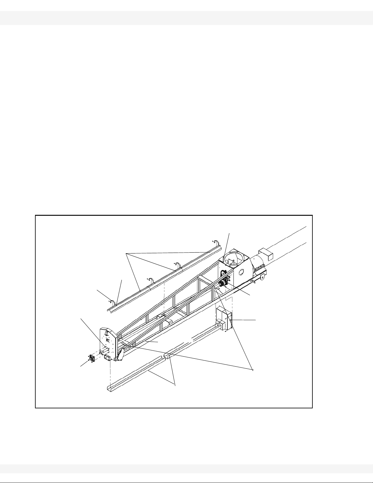
20. Install two sections of lower driveshaft guard as well ad the driveshaft guard
extension with 3/8” x 1” carriage bolts and 3/8” x 1” bolts and flange nuts.
Tighten the guard extension and lower half of the guard. Leave the top half
hand tight until the two piece chain guard is in place. Figure 3.5.
end of the flex frame.
24 30651 R5
WHEATHEART - SA FLEX AUGER 3. ASSEMBLY
SPROCKET
COVER
FLEX FRAME
SMS #14 X 5/8”
WITH
WASHERHEAD
DRIVESHAFT
SHIELD
STRAP
DRIVESHAFT
SHIELDS
5/8” LOCKNUTS
LOWER
DRIVESHAFT
GUARD
5/8” X 1-3/4”
BOLTS
FLEX FRAME
BOOT
LOWER
FLIGHT SHAFT
3/8” X1” CARRIAGE
BOLTS
71’ - 111’ 3.1. TUBES & FLIGHTING
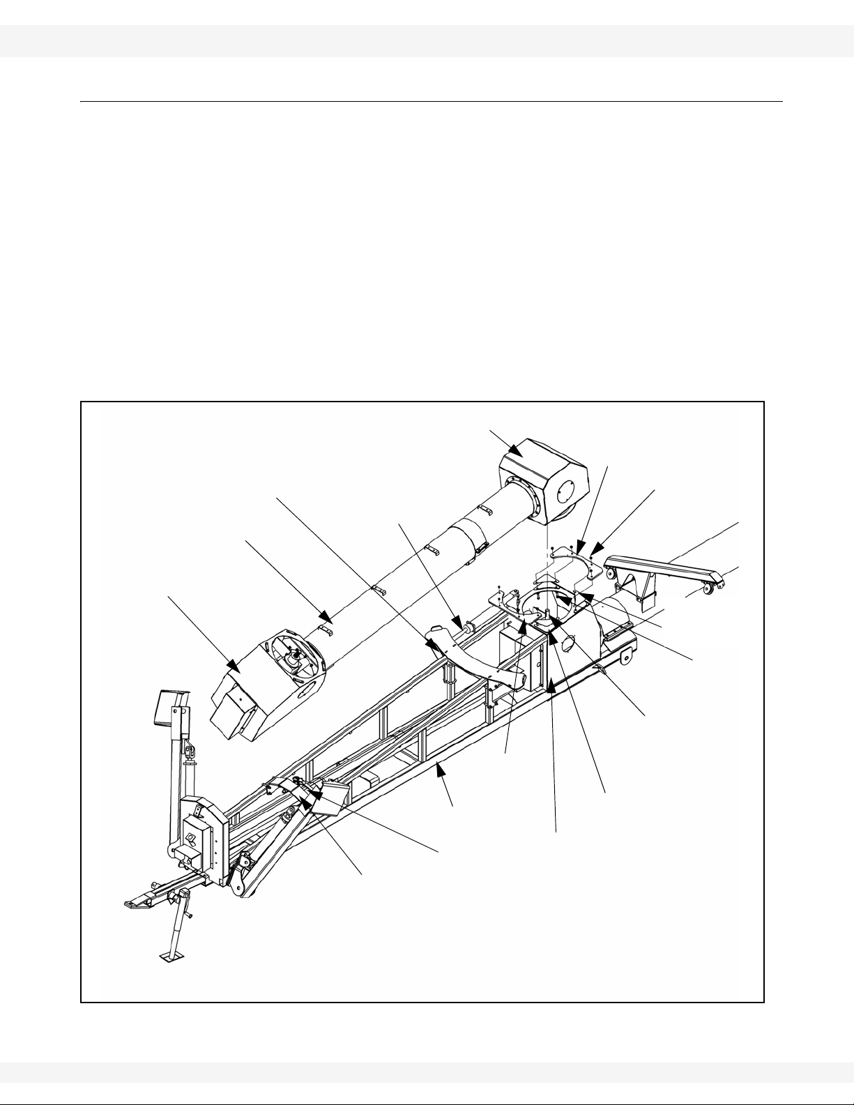
21. Place bracket under middle of driveline with spacer and use shims provided
to level.
22. To install chain coupler (shipped assembled):
a. On the two half-sprockets: check to make sure the keyways are NOT lined
up. If they are, disassemble the chain coupler and offset the keyways, then
reassemble.
b. Slide the chain coupler onto the lower flight stub shaft, and attach it using
3/8” x 2-1/2” roll pin.
c. Install the 3/8” x 1-3/4” square key onto the solid driveshaft, and slide the
driveshaft into the opposite end of the chain coupler . Slide it in 1-3/4”, until
the end of the driveshaft is flush with the end of the sprocket.
d. Secure both sides of the chain coupler using the setscrews; tighten
securely.
e. Disassemble the 1-3/4” wooden bearing (as supplied). Re-assemble the
bearing around the solid driveshaft, and attach it to the frame using two
3/8” x 2-1/4” bolts and locknuts provided. Use shims as necessary; wood
bearing is there for support only, DO NOT force shims into place. Once
satisfied with driveline alignment, tighten bolts and locknuts securely.
Figure 3.6
30651 R5 25
23. Secure the driveshaft to the front plate of the flex frame with a 1-3/4” bearing
and flange and four 5/8” x 1-3/4” bolts and locknuts. Secure lower driveshaft
with locking collar and setscrew.
24. Grease zerk should be located on left side of bearing.
3. ASSEMBLY WHEATHEART - SA FLEX AUGER
1/2” X 2” X 3-1/4”
U-BOLT
LEFT OUTRIGGER LEG
1/2” X 1-1/2”
CARRIAGE BOLT
5/16” LOCKNUT
RIGHT OUTRIGGER LEG
SPROCKET
GUARD
5/16” X 3/4”
BOLT
5/16” X 3/4”
BOLT
ROLLER SUPPORT
TRANSPORT REST
1/2” LOCKNUT
1/2” LOCKNUT
1/2” X 2” X 3-1/4” U-BOLT
3.2. FLEX FRAME COMPONENTS 71’ - 111’
25. Attach sprocket covers to flex frame boot with four 5/16” x 3/4” bolts and
locknuts.
26. Place two 60” and one 48” driveline guards over shaft and secure to flex
frame with driveshaft shield straps and SMS #14 x 5/8” with washerhead.
3.2. FLEX FRAME COMPONENTS
Figure 3.7
Important: There is a left and a right outrigger leg. Ensure they are installed with ports facing
26 30651 R5
1. Install outrigger legs. Insert 1/2” x 1-1/2” carriage bolts pointing inward to
prevent interference with hydraulic cylinder.
the discharge.
2. Place roller support inside key stops on flex frame, see Figure 3.7. The four
1/2” x 2” x 3-3/4” u-bolts are attached around the upright tubes, as shown in
Figure 3.7. Ensure that these u-bolts are tightened securely.
3. Install sprocket guard on boot with four 5/16” x 3/4” bolts. Ensure that tabs on
2 piece sprocket guard are fit into the slots on either side of the lower guard.
Tighten the top half of the lower guard.
4. Attach the transport rest to flex frame with four 1/2” X 2” x 3-1/4 u-bolts and
locknuts. Leave flex tube support transfer rest untightened until after the flex
tube is installed.
WHEATHEART - SA FLEX AUGER 3. ASSEMBLY
Figure 3.8
ROTATE FLEX BOOT
AS SHOWN BY
ARROW FOR LEFT
SIDE USE
BOOT SPINNER PLATE
Note:
7/16” X 1-1/4”
BOLTS
7/16” WASHERS & LOCKNUTS
Figure 3.9
Important:
71’ - 111’ 3.3. FLEX AUGER BOOT
3.3. FLEX AUGER BOOT
.
Complete assembly in the order listed to prevent premature failure of the lower
bearing. Refer to Figure 3.8 to 3.10.
1. Attach boot spinner plates.
a. Insert plates between boot spinner and
upper flex tube bundle.
b. Mount onto the four 7/16” x 1-3/4” bolts
welded to the tube.
c. Fasten with 7/16” locknuts and 7/16”
washers.
d. Do not tighten all the way.
e. Ensure boot is angled on the same side as
swing tube is to be installed.
f. Secure with eight 7/16” x 1-1/4” bolts with
locknuts and washer.
Flex boot can be rotated to the left or the right side
of the auger. Figure 3.9 and 3.10 show setup for
swing on right side of the auger, as viewed from
the intake end facing toward the spout. To install
the flex boot on left side, rotate boot to left side
2. Place 1-3/4” wide rim washer and 1-3/4”
Grease zerk should be
located on left side of
bearing.
3. Install square key and
4. Align lower sprocket with
5. Install roller chain on
bearing and flange on flight shaft with 5/8” x 1-3/4” bolts and locknuts. Do not
tighten until Step 5.
slide lower sprocket onto
flight shaft.
upper sprocket using
straight edge, then
tighten set screws.
sprockets and adjust
tension to about 1/4”
(0.64 cm) deflection.
Tighten the 4 bolts on
lower bearing and
secure lock collar. Oil
chain lightly.
30651 R5 27
3. ASSEMBLY WHEATHEART - SA FLEX AUGER
HALF BAND
7/16”
LOCKNUTS
PIVOT
SUPPORT
FLEX TUBE
7/16” X 1-1/4” BOLT
FLIGHT SHAFT
3/8” X 3-1/2”
SQUARE KEY
LOWER SPROCKET
1-3/4” WIDE
RIM WASHER
5/16” X 3/4” BOLT”
CHAIN
GUARD
9”
UPPER
SPROCKET
F
L
E
X
B
O
O
T
LOWER
SPROCKET
NOTE:
GREASE
ZERK TO
LEFT SIDE
ROLLER CHAIN
7/16” X 1-1/4”
BOLT
1-3/4” BEARING &
FLANGE
SPOUT PLATE
3.3. FLEX AUGER BOOT 71’ - 111’
6. Bolt chain guard on boot with four 5/16” x 3/4” bolts and locknuts.
7. Bolt half band and pivot support together with 7/16” x 1-1/4” bolts and
locknuts on flex tube, 24” (61.0 cm) from spout plate. See Figure 3.10.
Figure 3.10
28 30651 R5
WHEATHEART - SA FLEX AUGER 3. ASSEMBLY
FLEX TUBE
HYDRAULIC
CYLINDER
2-1/2” X 16”
UPPER PIVOT PLATE
WITH GREASE FITTINGS
7/16” X 1-3/4”
BOLT AND 7/16”
FLAT WASHER
LOWER PIVOT
PLATE
FOUR GALVANIZED
SPACERS
FLEX FRAME
FLEX TUBE SUPPORT
FLEX TUBE
BOOT
CYLINDER
BRACKET
FLEX SPOUT
GEARBOX SHAFT
WIDE RIM FLAT WASHER,
AND 1/4” X 1-1/4” KEY
FLEX FRAME
BOOT
SPRING PIN
7/16” LOCKNUT
TWO
GALVANIZED
SPACERS
71’ - 111’ 3.4. CONNECTING FLEX TUBE TO FLEX FRAME
3.4. CONNECTING FLEX TUBE TO FLEX FRAME
1. Place wide rim flat washer and 1/4” x 1-1/4” key on the gearbox shaft.
2. Place upper flex tube on flex frame as shown aligning u-joint in flex tube
spout on the gearbox in the boot.
3. Place 6 galvanized spacers (4 in front, 2 in back) and 2 pivot plates on flex
frame boot. Secure flex spout on flex frame with 7/16” x 1-3/4” bolts and
locknuts.
• Upper plate has grease nipples on it; the lower plate does not.
• Grease nipples are in bolt bag and need to be installed.
Important: Pivot plates must be installed as illustrated.
4. Install 2-1/2” x 16” cylinder to flex spout and cylinder bracket as shown in
Figure 3.11. Use two 1/4” x 1-3/4” cotter pins to assemble cylinder pin and
use snap rings provided to assemble clevis pin.
Figure 3.11
30651 R5 29
3. ASSEMBLY WHEATHEART - SA FLEX AUGER
Figure 3.12
LOCK PIN
TRANSPORT
LATCH
Figure 3.13
3.5. ADJUSTABLE TOWBAR 71’ - 111’
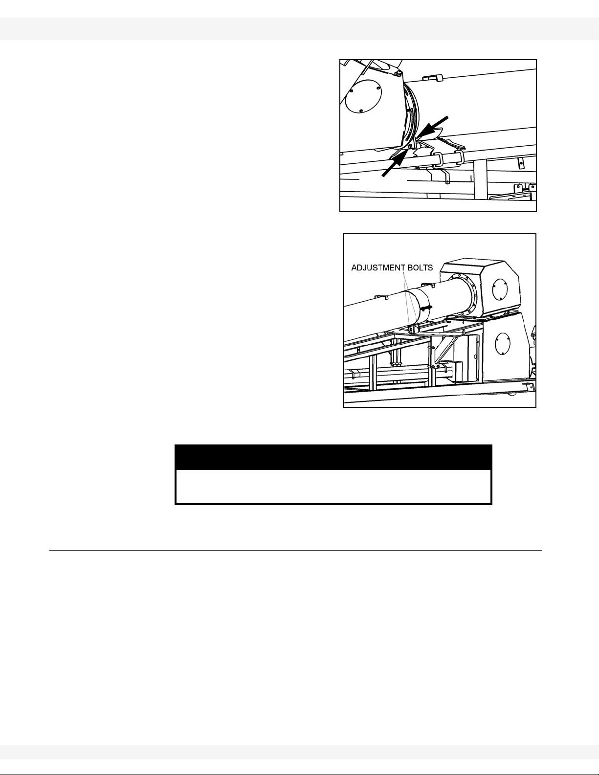
5. Adjust the position of the flex tube
support, so that the lock pin sticks
through the transport latch approximately 1/16” (1.6 mm). Tighten ubolts and locknuts and secure. See
Figure 3.12.
6. Use a hoist to lift the lower end of
flex tube slightly and adjust the
position of the pivot roller with the
1/2” x 2-1/2” adjustment bolts to
carry the weight of the flex tube. See
Figure 3.13.
Failure to lift the flex tube when adjusting the pivot roller can
result in damage to the roller and/or flex tube.
3.5. ADJUSTABLE TOWBAR
Important: Adjust the towbar if a speed-reducing gearbox is used with the system. In this
The Flex has an adjustable towbar. The towbar is installed as seen in Figure
3.14.
1. Insert the adjustable towbar into the boot channel. Secure by placing a 3/4” x
6-1/2” long bolt and locknut through the back hole in the boot channel, under
the flex frame.
2. Insert a 5/8” x 4-1/2” long bolt and locknut vertically into the hole at the front
of the boot so that the towbar comes straight out from the flex frame.
• This bolt must be inserted from the bottom with the nut on top.
case, the towbar is extended and pinned on an angle using the vertical bolt. This
will line up the PTO with the PTO connection on the gearbox.
NOTICE
30 30651 R5

WHEATHEART - SA FLEX AUGER 3. ASSEMBLY
ADJUSTABLE
TOWBAR
BOOT CHANNEL
3/4” X 6-1/2”
BOLT &
LOCKNUT
5/8” X 4-1/2”
BOLT &
LOCKNUT
PTO CRADLE
BRACKET
71’ - 111’ 3.6. DISCHARGE SPOUT & THRUST ADJUSTER
3. Install the PTO cradle bracket on the front plate of the flex frame. Attach
bracket with two 7/16” x 1-1/4” bolts and locknuts.
3.6. DISCHARGE SPOUT & THRUST ADJUSTER
Figure 3.14
• Attach discharge spout with
7/16” x 1-1/4” bolts and locknuts.
• The thrust adjuster is designed
to transfer some pressure from
the lower flight bearing to the
upper flight bearing.
• Remove cover and 5/8”
whiz nuts.
• Loosen the set screw on
the lock collar and disengage the lock collar from
the bearing to allow free
movement of the flight
shaft.
• Turn the 1-1/2” nut until it is snug against the bushing, then turn it so that
the flight shaft moves an additional 1/4” (0.64 cm).
• Secure the lock collar and tighten the set screw.
• Re-install the cover over the two longer 5/8” bolts. Secure with two 5/8”
whiz nuts.
30651 R5 31

3. ASSEMBLY WHEATHEART - SA FLEX AUGER
WELD ON
TAB
3.7. TRUSS 71’–91’ 71’ - 111’
3.7. TRUSS 71’–91’
1. Fasten the 3 cable bridges (5) to the brackets (6) with two 7/16” x 1-1/4” GR5
bolts (3) and 7/16” locknuts (4) per cable bridge. Refer to Figure 3.15.
Important: 1371 and 1381 Only: The largest cable bridge is 35” (0.89 m) high and attaches
to the center bracket. The other 2 cable bridges are 17” high and attach to the
outside brackets.
1391 Only: The largest cable bridge is 35” (0.89 m) high and attaches to the
center bracket. The other 2 cable bridges are 32” (0.81 m) high and attach to the
outside brackets.
Refer to Figure 3.16 and 3.17 for remaining steps.
2. Leave a stand at each end of the tube sections but remove the rest of the
stands and let the tube deflect under its own weight.
Note: 1371 auger uses two cables 58’ (17.7 m) and 91’ (27.7 m) long.
1381 auger uses two cables 75’ (22.9 m) and 115’ (35.1 m) long.
1391 auger uses two cables 90’ (27.4 m) and 134’ (40.8 m) long.
3. Attach an eyebolt (1) to one end of each truss cable (2 and 3) with two 3/8”
cable clamps (4) doubling-back about 12” (0.30 m) of cable. Insert the
eyebolts into the appropriate weld on tab (5) and thread on a 1/2” locknut (6)
a short way.
Figure 3.15
32 30651 R5

WHEATHEART - SA FLEX AUGER 3. ASSEMBLY
71’ - 111’ 3.7. TRUSS 71’–91’
4. Pull the long truss cable (2):
• over the cable bridges (7)
• around the cable return bracket (8)
• back over the cable bridges (7)
• back to the cable anchor racket (5)
5. Pull the short truss cable (3):
• over the middle cable bridge (7)
• around the cable return bracket (8)
• back over the middle cable bridge (7)
• back to the cable anchor bracket (5)
Important: The long truss cable (2) must be installed on the outside of the middle bridge (7).
6. Use loosely attached 5/16” cable clamps to hold the cable in place — 2 cable
clamps per cable bridge and two clamps on the cable return bracket.
Note: Do not tighten the cable clamps at this time.
7. Place another eyebolt in each weld on tab and thread on a 1/2” locknut a
short way.
8. Thread the end of each truss cable through the appropriate eyebolt and pull
the cable snug. Double-back the cable and secure in place with two 3/8”
cable clamps as in Step 2.
Figure 3.16
30651 R5 33

3. ASSEMBLY WHEATHEART - SA FLEX AUGER
STANDARD SUPPORT
TRUSS BRACKET
HIGH TRUSS
SUPPORT BRACKETS
ANCHOR BRACKET
STANDARD SUPPORT
TRUSS BRACKET
HIGH TRUSS
SUPPORT BRAKCET
ANCHOR BRACKET
71’
81’
HIGH TRUSS
SUPPORT BRAKCET
TRUSS SUPPORT
BRAKCET
TRUSS SUPPORT
BRAKCET
ANCHOR BRACKET
91’
3.7. TRUSS 71’–91’ 71’ - 111’
Note: If there isn’t enough cable, loosen the clamps on the opposite eyebolt and adjust
the cable. Retighten clamps.
9. Tighten the eyebolts on the long cable (2) evenly to take the remaining slack
out of the truss cable. Once the long cable (2) is tightened, repeat for the
short cable (3).
10. Check for proper side-to-side alignment and then tighten the cable clamps on
the cable bridges and the cable return brackets.
Figure 3.17 Flex 71’, 81’, and 91’ Auger Complete Truss Layout
34 30651 R5

WHEATHEART - SA FLEX AUGER 3. ASSEMBLY
71’ - 111’ 3.8. TRUSS 111’
3.8. TRUSS 111’
When assembling the truss system, do not tighten any bolts until all components are in place. Refer to Figure 3.18 on page 36 for correct positioning of the
truss components.
1. Loosely attach the 2 low pairs of truss towers (D) and 57 (111') high pairs of
truss towers (C) to the truss-attach brackets welded to auger tube with 7/16”
x 1-1/4” bolts and locknuts.
2. Loosely join the ends of two 10' (3.05 m) truss tubes (A) and two crossbrace
tubes (B) between the top end of each pair of high truss towers using 1/2” x
2-3/4” bolts and locknuts.
3. Thread a 3/4” nut onto each adjust-tube, then insert threaded end into trussanchors on lower and upper auger tubes. Join the adjust tubes (E) and 10'
truss tubes (A) at the two low (D) truss towers with 1/2” x 2-3/4” bolts and
locknuts.
Note: A single crossbrace tube is positioned between the low (D) truss towers and
adjacent high (C) truss towers.
4. Loosely join all the crossbrace tubes to t abs welded to top of truss-attach
brackets using 1/2” x 1-1/2” bolts and locknuts.
Note: Attach these tubes to same side of tab as they are attached to the truss tower.
5. Tighten all bolts and nuts.
6. Install the 5 (111') pairs of x-clamps where the crossbrace tubes meet with
two 7/16” x 1" bolts and locknuts on each.
7. Thread a second 3/4” nut on the end of the adjust tube, then adjust the
threaded adjust tubes until upper and lower auger tubes have a slight upward
bow. Lock the adjust nuts against bracket.
30651 R5 35

3. ASSEMBLY WHEATHEART - SA FLEX AUGER
3.8. TRUSS 111’ 71’ - 111’
Figure 3.18
36 30651 R5

WHEATHEART - SA FLEX AUGER 3. ASSEMBLY
Figure 3.19 111‘Auger
10-12”
(25.4 - 30.5 cm)
ADJUST
BRACKET
EYEBOLT
NUT
3/8” CABLE CLAMPS
71’ - 111’ 3.8. TRUSS 111’
3.8.1. CABLE TRUSSING
1. Attach an eyebolt to one end of each of two
truss side cables with two 3/8” cable clamps using
about 10” (25.4 cm) to 12” (30.5 cm) of cable.
Tighten securely (Figure 3.20).
2. Insert eyebolts into tabs located on flex frame.
Secure with 1/2” locknut (Figure 3.19).
3. Loosely attach the truss cables to each cable
support arm with a 5/16” cable clamp as shown in
Figure 3.18.
4. Attach remaining eyebolts to adjust bracket and
thread on 1/2” locknuts about 1/2” (Figure 3.20).
5. Thread loose ends of the cable through each
eyebolt, pull tight, then secure with two 3/8” cable
clamps (Figure 3.20). Tighten securely.
6. Adjust tension of side truss cable by tightening
the eyebolts at the adjust brackets. These cables
must be very tight. Also adjust for side alignment.
7. Now tighten all of the cable clamps at cable
supports and arms.
Figure 3.20
30651 R5 37

3. ASSEMBLY WHEATHEART - SA FLEX AUGER
3.9. SCISSOR LIFT FRAME (71’–91’) 71’ - 111’
Figure 3.21
3.9. SCISSOR LIFT FRAME (71’–91’)
3.9.1. SCISSOR FRAME ASSEMBLY
WARNING
Components are heavy and create a crushing
and pinching hazard if improperly handled. Be
sure to use proper hoisting equipment and
procedures, and ensure lifting apparatus is
secure. Lockout the lifting apparatus before
working around or under the raised
components. Failure to do so may cause
serious personal injury .
Note: Refer to Table 3.2 and Figure 3.24 – 3.29 for the length of each auger
component.
38 30651 R5

WHEATHEART - SA FLEX AUGER 3. ASSEMBLY
71’ - 111’ 3.9. SCISSOR LIFT FRAME (71’–91’)
1. Wheel hub assembly:
a. Remove any dirt or paint from spindle and hub.
b. Thoroughly pack wheel bearings and cups with a good grade of bearing
grease.
c. Place large bearing into hub and carefully tap in seal.
d. Slip hub onto spindle and insert small bearing.
e. Tighten slotted spindle nut until hub drags slightly. Back off nut about 1/4
turn until hub turns freely.
f. Install cotter pin and dust cap.
Note: Installing tires may not leave you with enough clearance to position and attach
undercarriage once auger tube is raised. If so, install wheels after assembly is
complete.
g. Check that pressure of pre-inflated tires matches pressure indicated on tire
sidewall. Mount wheels on hubs and attach with six 1/2” x 1-3/4” wheel
bolts.
Figure 3.22
2. Mount wheels (1) to hubs (2) on axle extension (3) with 6 wheel bolts (4).
Note: Before mounting the wheels, check to make sure the hub and wheel mounting
surfaces are free from rust and debris.
3. Finger tighten the wheel bolts and verify that the wheel is sitting flush on the
hub. Torque the wheel bolts to 80 ft-lb (±10 ft-lb) of torque while using the
appropriate criss-cross pattern; refer to Appendix for specifications. If in
doubt, have a qualified tire repair service perform required maintenance.
4. For 71’, 81’, and 91’ augers, insert axle extensions (5) into axle (3) and pin it
in place using a 3/8” x 5-1/2” pin (6) and hitch pin (7).
30651 R5 39

3. ASSEMBLY WHEATHEART - SA FLEX AUGER
3.9. SCISSOR LIFT FRAME (71’–91’) 71’ - 111’
5. Attach the lower arms (8) to the axle (3) using two 3/4” x 3-1/2” x 5” u-bolts
(9) and four 3/4” locknuts (10). Space the lower arms evenly on the axle at
102” (2.59 m). (Figure 3.29).
6. Tighten the u-bolts evenly by alternating between the top and bottom
locknuts.
7. Place a board across the lower arms to support the lower scissor arms.
8. Bolt the lower scissor arms (14 and 15) to the axle (3) with 1” x 3” bolts (16)
and 1” locknuts (17).
Note: Ensure the arms are located on the correct side. The hole in the axle tab should
be at the bottom.
9. Attach the lower cylinder mount (18) to the lower scissor arms (14 and 15)
using 1” x 6” x 5” u-bolts (19) and 1” locknuts (20) on 71’, 81’, 91’. See
Figure 3.27.
10. Position the brace between the tab stops. Don’t tighten.
11. Attach the lower x-brace (21) to the lower scissor arms (14 and 15) using
1” x 6” x 5” u-bolts (22) and 1” locknuts (23) on the 71’, 81’, and 91’.
12. Position the brace against the tab stops so the tabs are on the axle side of
the lower x-brace. Don’t tighten.
13. Pin the upper scissor (24) to the lower scissor arms (14 and 15) using a
1-1/2” x 4-1/2” bolts (25), 1-1/2” SAE flat washer (26), and 1-1/2” locknut (27).
• Use two 1-1/2” SAE washers (28) as spacers between the upper and
lower scissor tabs.
14. Tighten the locknuts (20) on the u-bolts (19) for the lower cylinder mount (18):
a. Start with the locknuts closest to the axle.
b. While tightening, ensure that the lower cylinder mount (18) butts up against
the tab stops on the lift arms (14 and 15) using the same procedure as in
Steps 5. and 6.
c. Tighten the remaining u-bolts and repeat the procedure for the lower x-
brace (21).
15. Attach skid plate and back plate to axle arm 65” (1.65 m) from the axle arm
with 1/2 X 1-1/4 bolts and 1/2” locknuts. See Figure 3.23.
40 30651 R5

WHEATHEART - SA FLEX AUGER 3. ASSEMBLY
65”
(1.65 M)
SKID PLATE
1/2 X 1-1/4” BOLT
SKID BACK PLATE
71’ - 111’ 3.9. SCISSOR LIFT FRAME (71’–91’)
Figure 3.23
30651 R5 41

3. ASSEMBLY WHEATHEART - SA FLEX AUGER
3.9. SCISSOR LIFT FRAME (71’–91’) 71’ - 111’
Figure 3.24
42 30651 R5

WHEATHEART - SA FLEX AUGER 3. ASSEMBLY
U
V
W
TOP VIEW
SIDE VIEW
71’ - 111’ 3.9. SCISSOR LIFT FRAME (71’–91’)
Figure 3.25 TOP VIEW
Figure 3.26 Top & Side View
30651 R5 43

3. ASSEMBLY WHEATHEART - SA FLEX AUGER
3.9. SCISSOR LIFT FRAME (71’–91’) 71’ - 111’
Figure 3.27 Top View
Figure 3.28 Top View
Figure 3.29
44 30651 R5

WHEATHEART - SA FLEX AUGER 3. ASSEMBLY
71’ - 111’ 3.9. SCISSOR LIFT FRAME (71’–91’)
Table 3.2
Model U V W X Y Z
71’
81’
91’
167”
(4.24 m)
178”
(4.52 m)
220”
(5.59 m)
89”
(2.26 m)
71”
(1.80 m)
112”
(2.84 m)
149” w/ Trussing
(3.78 m)
167-3/4” w/ Trussing
(4.26 m)
189-1/2” w/ Trussing
(4.81 m)
60-1/8”
(1.52 m)
59-13/16”
(1.52 m)
58-7/16”
(1.48 m)
229”
(5.82 m)
288”
(7.32 m)
353”
(8.97 m)
102”
(2.59 m)
102”
(2.59 m)
102”
(2.59 m)
3.9.2. ATTACHING TO TUBE
1. Remove the stand from the intake end of the auger and raise the discharge
end with a block and tackle or a front end loader and a strong sling or chain
at point “A” (Figure 3.31). Height should be sufficient so the frame can be
positioned under the tube.
WARNING
Components are heavy and create a crushing
and pinching hazard if improperly handled. Be
sure to use proper hoisting equipment and
procedures, and ensure lifting apparatus is
secure before working around or under the
raised components. Failure to do so may
cause serious personal injury.
2. Position the frame under the tube assembly.
3. Lower the tube to align the upper scissor with the bracket closest to the
center cable bridge on the tube (29).
• Secure in place using 1” x 2-1/2” bolts (30) and 1” locknuts (31).
• Use two 1” SAE washers (32) as spacers between the tabs and the
bracket (1 for each side). See Figure 3.24.
30651 R5 45

3. ASSEMBLY WHEATHEART - SA FLEX AUGER
3.9. SCISSOR LIFT FRAME (71’–91’) 71’ - 111’
4. Raise the tube at point “A” so the discharge end is approximately 10’ off the
ground.
• Attach a lifting device at point “B” on the scissor-lift frame and lift until the
axle arms (8) are aligned with the lower bracket (first bracket from the
intake end) on the tube (33).
• Tighten with 1” x 2-1/2” bolts (30) and 1” locknuts (31). Use 1” SAE washers (32) as spacers between the tabs and the bracket (one for each side).
See Figure 3.24.
WARNING
Do not remove tube support until instructed to
do so in step 12.
5. Attach axle arms to flex frame as shown in Figure 3.30. Start by passing a 1”
x 5” bolt through the axle arm, stabilizer bracket, 1” flat washers and the push
the bolt through the hole in the flex frame. Secure on the backside with a 1”
locknut. This is a pivot point, tighten only to snug. Repeat this process for the
opposite side.
Note: It may aid alignment to use a stand to hold up the axle arms.
6. Install the short crossmember by placing it between the lower arms. Attach a
stabilizer side plate to each end of the short crossmember and secure with
four 3/4” x 4-1/2” bolts and locknuts. Only put the nuts on the end of the bolts
for now.
7. Attach the stabilizer braces to the short crossmember using a 5/8” x 2” bolt
and locknut. Leave the bolts loose for now.
Note: The bend angle of the stabilizer brace is different at each end. Attach the end
with a smaller bend to the short crossmember.
8. Secure the two stabilizer brackets and stabilizer braces using a 5/8” x 2-1/2”
bolt and locknut. The stabilizer braces should sandwich the brackets. The
short crossmember may have to be moved around to get the bolt in.
9. Bolt the remaining hole in the two stabilizer brackets together with a 5/8” x
1-3/4” bolt and locknut.
10. Push the short crossmember toward the stabilizer brackets until it fits gently
between the two frames, do not wedge the short crossmember in between
the lower arms too tight.
11. Tighten all the bolts in the stabilizer and crossmember making sure nothing
moves. Ensure the 1” lower arm bolt is left only snug, as it remains a pivot.
46 30651 R5

WHEATHEART - SA FLEX AUGER 3. ASSEMBLY
STABILIZER
BRACKET
STABILIZER
BRACE
SHORT
CROSSMEMBER
3/4” X 4-1/2”
BOLT
AXLE ARM
SIDE PLATE
5/8” X 2”
BOLT &
LOCKNUT
3/4” LOCKNUT
5/8” X 2-1/2”
BOLT &
LOCKNUT
5/8” X 1-3/4” BOLT
& LOCKNUT
FLEX FRAME
1” X 5” BOLT &
1” FLAT WASHER
71’ - 111’ 3.9. SCISSOR LIFT FRAME (71’–91’)
Figure 3.30
12. Remove the lifting device at point “B” and raise the auger at point “A” so the
transport brace (34) can be attached. Use eight 1/2” x 1-1/2” bolts (35) and
1/2” locknuts (36). See Figure 3.24.
13. Lower the auger until the transport brace (34) is resting on the lower
x-brace (21) and remove the lifting device at point “A”. See Figure 3.31.
14. Fasten the x-brace tubes (11) to the axle arms (8) and secure with 1/2” x
1-1/2” bolts (12) and locknuts (13). See Figure 3.24.
Figure 3.31
30651 R5 47

3. ASSEMBLY WHEATHEART - SA FLEX AUGER
3.10. TRANSPORT UNDERCARRIAGE (111’) 71’ - 111’
3.10. TRANSPORT UNDERCARRIAGE (111’)
See Figure 3.32.
1. With truss on axle positioned as shown in Figure 3.32, fasten the lower reach
arms to brackets on axle with four 5/8” x 2" bolts and locknuts on each side.
2. Attach short crossmember loosely with two 5/8” x 2" bolts and locknuts,
sandwiching flat braces (B) between crossmember and frame bracket. Do
not tighten bolts until undercarriage is beneath tube assembly (Figure 3.34).
3. Secure the tubing crossbraces to welded lugs on lower reach arms with two
1/2” x 1-1/4” bolts and locknuts, plus a third one where the braces cross. Add
a tie tube between the bottom welded lugs. Use three 1/2” x 1-1/4” bolts and
two 1/2” x 1/3/4” bolts and 1/2” locknuts.
4. Attach the axle crossbraces with two 1/2” x 1-1/4” bolts and locknuts each.
5. Insert axle extensions into axle and pin in place using a saddle pin and hair
pin.
6. Wheel hub assembly:
a. Remove any dirt from spindle and hub.
b. Thoroughly pack wheel bearings and cups with a good grade of bearing
grease.
c. Place large bearing into hub and carefully tap in seal.
d. Slip hub onto spindle and insert small bearing and washer.
e. Tighten slotted spindle nut until hub drags slightly. Back off nut about 1/4
turn until hub turns freely.
f. Install cotter pin and dust cap.
Note: Installing tires may not leave you with enough clearance to position and attach
undercarriage once auger tube is raised. If so, install wheels after assembly is
complete.
7. Inflate to recommendations on tire side wall. Wheels may be mounted on
hubs at this time using 6 wheel bolts. Finger tighten the wheel bolts and verify
that the wheel is sitting flush on the hub. Torque the wheel bolts to 80 ft-lb
(±10 ft-lb) of torque while using the appropriate criss-cross pattern; refer to
Appendix for specifications. If in doubt, have a qualified tire repair service
perform required maintenance.
8. Fasten upper lift arms to lower reach arms using two 15/16” spacer bushings,
flat washers, and 1" x 3-1/2” bolts and locknuts. Tighten securely; lift arms
pivot on the spacer bushings (Figure 3.33).
48 30651 R5

WHEATHEART - SA FLEX AUGER 3. ASSEMBLY
(120” LONG)
(3.05 m)
(3.18 m)
71’ - 111’ 3.10. TRANSPORT UNDERCARRIAGE (111’)
.
Figure 3.32
30651 R5 49

3. ASSEMBLY WHEATHEART - SA FLEX AUGER
3.10. TRANSPORT UNDERCARRIAGE (111’) 71’ - 111’
Figure 3.33
9. Lower auger intake to the ground.
10. Raise the upper end of
auger with a block and
tackle or a front-end
loader. Securely attach
a strong sling or chain
about 36" above
trackstop. Secure tube
to prevent it from turning
while lifting. Raise
sufficiently to clear
undercarriage.
NOTICE
Do not remove tube support until assembly in this section
has been completed.
11. Place undercarriage beneath tube assembly.
12. Position stabilizer braces (A) (Figure 3.34) and attach lower reach arms to
bracket on tube with long spacer bushings (1-1/8” long), flat washers, and 1"
x 3-1/2” bolts and locknuts. Tighten securely. Reach arms pivot on the
spacer bushings.
50 30651 R5

WHEATHEART - SA FLEX AUGER 3. ASSEMBLY
Figure 3.35
71’ - 111’ 3.11. LIFT CABLES (111’)
Figure 3.34
13. Fasten flat braces (B)
to first set of holes
(furthest from intake)
on stabilizer braces (A)
with one 5/8” x 2" bolt
and locknut. Place one
5/8” x 1-1/8” bolt and
locknut in other hole of
stabilizer brace.
14. Attach upper lift arms to
center hole on the liftassist arms (Figure
3.35) with two 15/16”
medium spacers, flat
washers, and two 1" x
3-1/2” bolts and
locknuts. Tighten securely; lift arms will pivot on the spacer bushings.
15. Lower discharge end of auger slowly until track shoe rests against trackstop
and the lift-assist arm rests against track.
3.11. LIFT CABLES (111’)
Important: Lift cables may stretch with use. Check frequently and adjust when necessary.
30651 R5 51
1. Seat lift-assist arm against the track and place both lift cylinders in full down
position (fully retracted).
2. Thread the lift cables over the respective pulleys on the lift-assist arm, pull
cables tight, and secure with three 3/8” cable clamps on each cable. Tighten
securely. Do not crisscross cables (Figure 3.36).

3. ASSEMBLY WHEATHEART - SA FLEX AUGER
3.12. LIFT CYLINDER HYDRAULIC HOSES (111’) 71’ - 111’
Note: Although the lift cables are factory installed on the lift cylinders, make certain the
cable clamps at the cylinders are secure and the cables are properly seated in
the cable sheaves before attaching the cables to the lift-assist arm.
CAUTION
Track shoe must rest against trackstop when
adjusting cable.
If this isn’t done, auger can raise higher than
designed to, resulting in damage to auger and
possible injury to personnel.
Figure 3.36
3.12. LIFT CYLINDER HYDRAULIC HOSES (111’)
Note: Right or left side of auger , as referred to in this section, is determined by standing
at intake end facing top discharge end.
• Lower fittings refer to those closer to intake end of auger.
• Upper fittings refer to those closer to discharge end of auger.
Note: Use thread sealant (not supplied) on all hydraulic connections.
1. Position both elbow fittings on right cylinder. The lower one should face
forward and downward at approximately 45°. The upper one should face
rearward and downward at approximately 45° (Figure 3.37). Make certain
they are tight.
2. Secure the solid connector end of the short (17" / 0.43 m) cylinder-connector
hydraulic hose to the lower elbow fitting.
52 30651 R5
WHEATHEART - SA FLEX AUGER 3. ASSEMBLY
71’ - 111’ 3.12. LIFT CYLINDER HYDRAULIC HOSES (111’)
3. Secure the solid connector end of the long (32" / 0.81 m) cylinder-connector
hydraulic hose to the upper elbow fitting.
Note: Before attaching short connector hydraulic hose to left side lift cylinder, make
certain lift cables are tightly stretched and that this hose is positioned beneath
the lift cable on the left side lift cylinder (Figure 3.37). If lift cable is not installed
above this hose, it could result in the hose wearing through during operation,
causing a hazardous situation.
WARNING
Wear on hose can cause auger to drop
suddenly, causing serious injury or death.
4. Position the elbow fittings on the left cylinder. The lower one should face
forward and downward at approximately 45°. The upper one should face
rearward and upward at approximately 10°.
5. Secure the tee fittings to the left cylinder elbow fittings and position them as
shown in Figure 3.37. Make certain they are securely tightened.
6. Secure the swivel ends of the upper (32" / 0.81 m) and lower (17" / 0.43 m)
cylinder-connector hoses to the tees as shown.
7. Check upper 32" (0.81 m) cylinder-connector hose position to ensure there is
8-1/2” (0.22 m) clearance to lift cables as shown in Figure 3.37.
8. Attach the 392" (9.96 m) long pressure hose with shutoff valve to the lower
tee fitting (nearest auger intake).
9. Attach the 473" (12.0 m) long return hose without shutoff valve to the upper
tee fitting (nearest auger discharge end).
10. Thread hoses through back arm attach bracket as shown in Figure 3.37.
30651 R5 53

3. ASSEMBLY WHEATHEART - SA FLEX AUGER
BACK ARM
BRACKET
3.13. HYDRAULICS (71’–91’) 71’ - 111’
Figure 3.37
11. Place both hoses into retaining brackets welded to side of auger tube and
boot. Bend tops of brackets over slightly to hold hoses in place.
Important: Protect hose ends from dirt.
12. Recheck that bolts on undercarriage, lift cylinders, and cable clamps are
tight, then remove auger tube support.
3.13. HYDRAULICS (71’–91’)
3.13.1. CYLINDER INSTALLATION
Note: See Table 3.3 for the appropriate cylinders.
1. The transport brace (item 34 from Figure 3.24) must be installed and
supporting the frame.
2. Position the cylinders (1) on the cylinder lugs (2). The rod end of the
cylinders must be attached to the lower cylinder mount so that the rod
extends towards the intake (Figure 3.38).
Note: The ports need to be facing each other, see Figure 3.39.
54 30651 R5

WHEATHEART - SA FLEX AUGER 3. ASSEMBLY
71’ - 111’ 3.13. HYDRAULICS (71’–91’)
3. Pin the cylinders in place using 1” x 3-3/8” cylinder pins (3) and 1” external
hitch clips (4) (Figure 3.38).
Figure 3.38
V
Table 3.3
Auger Cylinder
71’ 4" x 36"
81’ 4" x 40"
91’ 4-1/2” x 40"
30651 R5 55

3. ASSEMBLY WHEATHEART - SA FLEX AUGER
3.13. HYDRAULICS (71’–91’) 71’ - 111’
3.13.2. HYDRAULIC CYLINDER PLUMBING
Note: Refer to Appendix for hydraulic fitting tightening specifications. Use pipe sealant
on all joints. See Table 3.4 for the proper hose length.
1. Remove plugs from the hydraulic cylinder.
2. Install elbow (2) into cylinder port.
3. Attach tee (4) to cylinder port. See Figure 3.39.
4. Attach the hydraulic hose end (5) to tee (4) (Figure 3.39).
5. Install hydraulic hose 3/8” x 2’ (1).
6. Lay the hose (8) (Figure 3.39) along the upper scissor and tube (Figure
3.40).
7. Secure the hydraulic hose along the top of the upper scissor and on the tube
using the welded hose clips.
8. Provide slack or a loop between each secured point.
9. Bend tops of welded clips over slightly to retain hose.
Important: Do not make bends in hydraulic hose too tight. The bends must have a radius of
at least 4” to prevent failure of the hose.
10. Install the ball valve (6), coupling (3), and optional pioneer tip (7) on the
hydraulic hose end (5) (Figure 3.39).
Table 3.4
Auger Hose Length
71’ 53’
(16.2 m)
81’ 58-1/2’
(17.8 m)
91’ 67’
(20.42 m)
Figure 3.39
56 30651 R5

WHEATHEART - SA FLEX AUGER 3. ASSEMBLY
71’ - 111’ 3.14. PTO (CV) DRIVELINE
Figure 3.40
3.14. PTO (CV) DRIVELINE
1. Clean PTO driveline and drive shaft ends of any paint or dirt.
Important: Ensure that a 3/8” x 3-1/2” square key is installed in the drive shaft before
attaching PTO driveline.
2. Slide plain end of PTO driveline onto drive shaft. Make sure that the holes for
the 3/8” roll pin are lined up and square key is in place.
30651 R5 57

3. ASSEMBLY WHEATHEART - SA FLEX AUGER
3.15. LOW PROFILE HOPPER 71’ - 111’
3. Making sure eyes are protected, carefully tap in roll pin. Tighten set screw .
4. Slide PTO transport saddle through support strap on boot and rest PTO
driveline in it until connected to tractor .
Figure 3.41
3.15. LOW PROFILE HOPPER
1. Attach the pivot-connector to the top hole in hopper with two 5/8” x 1-1/2”
bolts and locknuts. Do not over-tighten. Tighten snug only; these bolts act
as pivot points (Figure 3.43).
2. Loosely secure service door with 2 square latch-washers and 3/8” locknuts.
Note: Do not tighten until hopper assembly is completed.
3. Clean dirt from inside u-joint on hopper and flight shaft end, then insert
Woodruff key, see Figure 3.42.
4. Raise and support hopper tube at about 59" (1.5 m) under spout.
5. Open service door on hopper, then bring tube and hopper together guiding
flight shaft into u-joint.
6. Secure tube to pivot-connector on hopper with twelve 7/16” x 1-1/4” bolts and
locknuts.
58 30651 R5

WHEATHEART - SA FLEX AUGER 3. ASSEMBLY
FLIGHT SHAFT END
U-JOINT
HOLES FOR 5/8” X 1-1/2”
BOLTS AND LOCKNUTS
7/16” LOCKNUT
7/16” X 1-1/4” BOLTS
71’ - 111’ 3.15. LOW PROFILE HOPPER
Figure 3.42
Figure 3.43
7. Tighten set screws on u-joints, then close and secure the service door,
tighten 3/8” locknuts and 3/8” square latch washers.
8. Remove the two 5/16” whiznuts that secure the chain drive guard. Attach the
2-piece rubber extension to inside of hopper lip with 5/16” x 3/4” bolts and
whiznuts and the flat iron straps provided, plus the 2-piece extension
connector plates. Replace bolts, see Figure 3.43.
9. Attach two swivel wheels to the two hopper corners with eight 3/8” x 1”
carriage bolts and 3/8” whiz nuts (Figure 3.47).
30651 R5 59

3. ASSEMBLY WHEATHEART - SA FLEX AUGER
Figure
3.45
Figure
3.46
Figure
3.47
3.15. LOW PROFILE HOPPER 71’ - 111’
3.15.1. STEERING ASSEMBLY
Important: Hoppers can be set up for use on right or left side of auger. Figure 3.44 to 3.48
illustrate the right side as viewed when standing at the hopper looking toward the
spout. Figure 3.49 to 3.52 illustrate the left side as viewed when standing at the
hopper looking toward the spout.
1. Bolt short and long castor arms to hopper with four 3/8” x 1” bolts and 3/8”
flange nuts for each arm (Figure 3.45 and 3.46).
2. Insert steering shaft and motor castors through bearings on each castor arm.
Figure 3.44 Right Side Setup
60 30651 R5

WHEATHEART - SA FLEX AUGER 3. ASSEMBLY
3/8” X 2” BOLT
STEERING
SHAFT
STEERING
LINKAGE
3/8” X 1” BOLT
MOTOR
CASTOR
SPROCKET
FOLDABLE HANDLE
3/8” FLANGE NUT
STEERING COVER
STEERING CHAIN
SPROCKET
LONG CASTOR ARM
3/8” FLANGE NUT
1/4” X 1” WOODRUFF KEY
5/16” WHIZNUT
STEERING STOP
5/16” WHIZ NUT
STEERING LINKAGE
HOPPER
DRIVE
WHEEL
HYDRAULIC MOTOR
3/8” X 1” BOLT
3/8” FLANGE NUT
3/8” X 1-1/4” BOLT
AND LOCKWASHER
3/8” X 1” BOLT
AND
LOCKWASHER
NOTE: PORTS TO THIS SIDE
7/16” LOCKNUT
7/16” X 1-1/4” BOLT
SHORT CASTOR ARM
STEERING ARM
WELDMENT
MOTOR CASTOR
1/4” X 1” WOODRUFF KEY
71’ - 111’ 3.15. LOW PROFILE HOPPER
Figure 3.45 Right Side Setup
Figure 3.46 Right Side Setup
30651 R5 61

3. ASSEMBLY WHEATHEART - SA FLEX AUGER
3/8” x 1” CARRIAGE BOLT
HOPPER
3/8” WHIZ NUT
SWIVEL WHEEL
STEERING STOP
(UNDER SIDE)
STEERING STOP
3.15. LOW PROFILE HOPPER 71’ - 111’
Figure 3.47 Right Side Setup
Figure 3.48 Steering Stop Placement on Right Side Setup
62 30651 R5

WHEATHEART - SA FLEX AUGER 3. ASSEMBLY
Figure 3.50
Figure 3.51
Figure 3.52
71’ - 111’ 3.15. LOW PROFILE HOPPER
Figure 3.49 Left Side Setup
30651 R5 63

3. ASSEMBLY WHEATHEART - SA FLEX AUGER
3/8” X 2” BOLT
STEERING COVER
3/8” FLANGE NUT
SPROCKET
STEERING SHAFT
1/4” X 1” WOODRUFF KEY
5/16” WHIZNUT
STEERING STOP
FOLDABLE HANDLE
STEERING CHAIN
SPROCKET
MOTOR CASTOR
LONG CASTOR
ARM
3/8” FLANGE NUT
3/8” X 1” BOLT
STEERING
LINKAGE
STEERING STOP
5/16” WHIZ NUT
STEERING
LINKAGE
7/16”
LOCKNUT
STEERING ARM WELDMENT
7/16” X 1-1/4”
BOLT
1/4” X 1” WOODRUFF KEY
SHORT CASTOR ARM
HOPPER DRIVE
WHEEL
MOTOR CASTOR
HYDRAULIC MOTOR
3/8” X 1” BOLT AND
LOCKWASHER
NOTE: PORTS TO THIS SIDE
3/8” X 1-1/4”
BOLT AND
LOCKWASHER
3/8” FLANGE NUT
3/8” X 1” BOLT
3.15. LOW PROFILE HOPPER 71’ - 111’
Figure 3.50 Left Side Setup
Figure 3.51 Left Side Setup
64 30651 R5

WHEATHEART - SA FLEX AUGER 3. ASSEMBLY
HOPPER
3/8” X 1” CARRIAGE
BOLT
3/8” WHIZ NUT
SWIVEL WHEEL
STEERING STOP
(UNDER SIDE)
STEERING STOP
71’ - 111’ 3.15. LOW PROFILE HOPPER
Figure 3.52 Left Side Setup
30651 R5 65
Figure 3.53 Steering Stop Placement on Left Side Setup
3. Insert a sprocket on the steering shaft and on motor castor on the long castor
arm (on side with steering assembly). Connect sprockets with steering chain
and secure with connecting link and clip.
4. Place steering cover over chain and secure in place with eight 5/16” whiz nuts
(one whiz nut on each side of cover , 4 places).

3. ASSEMBLY WHEATHEART - SA FLEX AUGER
Figure 3.54 Right Side Setup
B
A
MAIN AUGER TUBE
STEERING ARM
WELDMENTS
STEERING
LINKAGE
NOTE: THE STEERING ARM WELDMENTS MUST
POINT TOWARD THE MAIN AUGER TUBE.
Figure 3.55 Left Side Setup
NOTE: THE STEERING ARM WELDMENTS MUST
POINT TOWARD THE MAIN AUGER TUBE.
MAIN AUGER TUBE
STEERING
LINKAGE
STEERING ARM
WELDMENT
B
A
3.15. LOW PROFILE HOPPER 71’ - 111’
5. Insert foldable handle over steering shaft; secure in place with a 3/8” x 2” bolt
and 3/8” flange nut. See Figure 3.45 for right side setup or Figure 3.50 for left
side setup.
6. Place steering stops on each steering shaft but do not tighten set screws until
Step 13.
7. Slide steering arm weldments over motor castors, secure in place with 1/4” x
1” key. Tighten setscrews on each side.
8. Points A and B on steering
arm weldments should point
at main auger. See Figure
3.54 for right side set-up, and
see Figure 3.55 for left side
set-up.
9. Place steering linkage on
holes nearest hopper on
steering arm weldments, see
Figure 3.54, or Figure 3.55.
Adjustment is built into
steering linkage to align tires
parallel to each other if
required. Secure with two
7/16” x 1-1/4” bolts and two
7/16” locknuts. Nuts should
be tight enough to hold
linkage in place but allow it to
move easily when using the steering arm.
10. Insert hydraulic motors
through motor castors and
secure with 3/8” x 1-1/4” bolts
and 3/8” lockwasher (4 bolts
per motor). Ensure motor
ports are installed towards
swing spout, as shown in
Figure 3.55 and 3.46. or 3.50
and 3.51.
11. Place hopper drive wheels on
hydraulic motor shafts,
securing in place with 1/4”
Woodruff key. Tighten
setscrews.
12. Install hopper drive wheel on
wheel hub with four 3/8” x 1”
bolts and 3/8” lockwashers.
13. Once set up for right or left
side use, turn handle so that wheels are 90° to the swing tube. Adjust position
of stops so that wheels cannot be turned further and tighten set screws
(Figure 3.48 for right-side setup, and Figure 3.53 for left-side set-up).
66 30651 R5
Continue to turn handle to ensure full 90° range.

WHEATHEART - SA FLEX AUGER 3. ASSEMBLY
Figure 3.56
BOOT
3/8” X 3/4” BOLTS
TAB
SPOUT HEAD RETAINER
LARGE
BOOT
RETAINER
SPACER
TOP “FEED” SIDE OF
HOPPER MUST F ACE
MAIN AUGER WHEN
IN TRANSPORT
POSITION
SADDLE PIN
HAIRPIN
71’ - 111’ 3.15. LOW PROFILE HOPPER
3.15.2. ATTACHING SWING TO FLEX AUGER
1. Clean u-joint spline and lower
gearbox spline, then apply a
light film of grease on splined
shaft.
2. Guide splined universal joint
onto splined shaft as the
intake hopper is lowered onto
the boot. Once positioned,
the swivel ring rests flat on
the boot surface and inside
the four spacer nuts.
3. Install four spout head
retainers and large boot
retainer spacers (galvanized)
with 3/8” x 3/4” bolts to keep
the intake hopper in place on
the boot.
4. Lubricate the universal joint and close the safety discharge door.
3.15.3. HOPPER LIFT ARM/WINCH
Figure 3.57
1. Choose either the right or left side; secure hopper lift arm assembly to the
mount bracket on top of the lower auger tube with two mount pins and
hairpins (Figure 3.59).
30651 R5 67
2. Attach the hydraulic winch and mount using hardware provided (Figure 3.58
and 3.59).

3. ASSEMBLY WHEATHEART - SA FLEX AUGER
3.15. LOW PROFILE HOPPER 71’ - 111’
3. Thread cable through pulley on lift arm and wrap around the winch drum,
starting at the top. Cable must have at least 3 complete wraps around the
drum when intake hopper is fully lowered (Figure 3.59). Trim excess cable.
WARNING
Falling auger hazard.
To prevent serious injury or death while
winching, ensure cable is fed onto the winch
drum as described.Replace cable if frayed or
damaged.
4. Tighten all hardware.
5. Install the valve, hydraulic fittings, and mount plate (Figure 3.58 and 3.60).
6. Connect hydraulic winch hoses to the valve on the front of the auger (Figure
3.60).
7. After the hydraulic system is completed, start the system and slowly activate
the hydraulic winch valve to take up the excess cable.
Figure 3.58
ITEM PART NO. DESCRIPTION QTY.
1 28879 HOPPER LIFT ARM WELD’T, MK FLEX 1
2 28885 LIFT ARM SPINDLE WELD’T, MK FLEX 2
3 18155 COTTER PIN, 3/16” x 1-1/4” 2
4 28836 LIFT ARM PULLEY ASSY, MK FLEX 2
HYDRAULIC WINCH KIT ONLY
ITEM PART NO. DESCRIPTION QTY.
5 17634 HYD WINCH ASSY 1
6 17675 HYDRAULIC VALVE 1
68 30651 R5

WHEATHEART - SA FLEX AUGER 3. ASSEMBLY
Figure 3.59
HOPPER LIFT ARM
MOUNT BRACKET
71’ - 111’ 3.15. LOW PROFILE HOPPER
HYDRAULIC WINCH KIT ONLY
ITEM PART NO. DESCRIPTION QTY.
7 17699 VALVE FITTI NGS 4
8 28923 HYD WINCH VALVE MOUNT, MK FLEX 1
9 28833 U-BOLT SQ 3/8” NC X 3-1/16” X 4” X 1” THD GR5 PLTD 2
10 28834 3/8” X 280” HYDRAULIC HOSE 2
11 28835 3/8” X 60” HYDRAULIC HOSE 2
- 16419 HYD WINCH BOLT BAG 1
- 17376 HOPPER LIFT CABLE, 1/4” X 31’ 1
8. Check the alignment of the winch
by watching the cable wrapping on
the drum as the swing tube is
raised. Proper alignment is
achieved when the cable indexes
properly filling each row on the
drum evenly and not piling up
against one side.
9. If the cable does not index properly ,
lower the swing tube fully until there
is slack in the cable. Loosen the
bolts on the winch. Adjust the
winch, retighten nuts, and retest.
30651 R5 69

3. ASSEMBLY WHEATHEART - SA FLEX AUGER
TO TRACTOR
PRESSURE
PORT
(NEW HOSE)
TO 3 SPOOL VALVE
PRESSURE SIDE
(EXISTING HOSE)
TO HYDRAULIC WINCH
TO HYDRAULIC WINCH
NEW VALVE
3.15. LOW PROFILE HOPPER 71’ - 111’
Figure 3.60
3.15.4. PLACING HOPPER INTO TRANSPORT POSITION
1. Attach cable hook to the loops inside the hopper (Figure 3.57).
2. Fully raise hopper with intake side facing towards the main auger as shown in
Figure 3.57.
3. Secure hopper to lift arm with hopper lock, saddle pin, and hairpin provided.
70 30651 R5

WHEATHEART - SA FLEX AUGER 3. ASSEMBLY
THIS CONFIGURATION
FOR RIGHT SIDE ONLY.
SWAP HOSES FOR
LEFT SIDE SETUP.
71’ - 111’ 3.16. FLEX AUGER HYDRAULICS
3.16. FLEX AUGER HYDRAULICS
Note: Hose layout is shown mounted on the right side of the auger as shown from the
hopper end facing toward the spout end. Hose layout will be mirrored from lower
boot to hopper if hopper mounted on left side.
Figure 3.61
1. Install all hose fittings and ball valves as shown in Figure 3.61 and described
in Table 3.5
Table 3.5
LABEL PART NO. DESCRIPTION LABEL
1 28751 3/8" X 88" HYDRAULIC HOSE, MK FLEX A 28763 STEEL TEE, 6MNPT X 6MJIC X 6MJIC RUN
2 28752 3/8" X 124" HYDRAULIC HOSE, MK FLEX B 28762 STEEL ELBOW 90, 6MJIC X 6FJIC
3 28755 3/8" X 64" HYDRAULIC HOSE, MK FLEX C 28764 STEEL ELBOW 90, 6MNPT X 6MNPT
4 28756 3/8" X 88" HYDRAULIC HOSE, MK FLEX D 18084 3/8 BALL VALVE
5 28754 3/8" X 52" HYDRAULIC HOSE, MK FLEX E 28757 STEEL ELBOW 90, 6MNPT X 6FNPSM
6 29205 3/8" X 125" HYDRAULIC HOSE, MK FLEX F 28758 STEEL ELBOW 45, 10MORB X 8MJIC
7 28834 3/8" X 280" HYDRAULIC HOSE, MK FLEX G 28760 STEEL, 10MORB X 8MJIC
30651 R5 71
PART
NO.
DESCRIPTION

3. ASSEMBLY WHEATHEART - SA FLEX AUGER
Figure 3.62
Figure 3.63
ASSEMBLE HOSES
HERE, REFERRING
TO CIRCLES FOR
COLOUR
RED
WHITE
YELLOW
GREEN
3.16. FLEX AUGER HYDRAULICS 71’ - 111’
Table 3.5
LABEL PART NO. DESCRIPTION LABEL
8 28835 3/8" X 78" HYDRAULIC HOSE, MK FLEX H 28761 STEEL ELBOW 90, 8MJIC X 8FJIC
29206 UPPER HOSE ASSEM, MK FLEX J 28759 STEEL ELBOW 90, 10MORB X 8MJIC
29207 LOWER HOSE ASSEM, MK FLEX K 28504 STEEL ELBOW 45, 6MORB X 6MJIC
L 28478 STEEL ELBOW 1/2MNPT X 1/2 FNPSM
M 28508 STEEL,8MORBX1/2FNPSMX1/16 ORIFICE
N 28654 #8 M-ORB-1/2F-NPT-90DEG FITTING
O 29087 STEEL ELBOW 90, 12MNPT X 8FNPSM
PART
NO.
DESCRIPTION
2. Loosely connect hydraulic hose
holders to swing and flex tubes.
Note that only two hose holders
are required at the top end of the
flex tube (Figure 3.70). Three
hose holders stacked together
can hold four hoses, two hose
holders stacked together can
hold two hoses. Refer to Figure
3.62.
• Three hose holders attach to
weldments with 3/8” x 3-1/2” bolts and locknuts.
• Two hose holders attach to weldments on tubes with 3/8” x 2-1/4” bolts
and locknuts.
3. Loosely connect
hydraulic hose
holders to hold four
hoses (see left side of
Figure 3.62) to
brackets on side of
flex frame as shown
in Figure 3.63.
4. Use hose bundle
marked with part
number 29207
(contains four hoses)
and secure to flex
tube as shown in
Figure 3.63 with hose
holders.
72 30651 R5

WHEATHEART - SA FLEX AUGER 3. ASSEMBLY
Figure 3.64
RED
WHITE
Figure 3.65
RED
WHITE
Figure 3.66
YELLOW
71’ - 111’ 3.16. FLEX AUGER HYDRAULICS
5. Continue to run hoses up flex tube and
down flex frame and secure to hose
holders as shown in Figure 3.64. Leave
6” (15.2 cm) between the hose sleeve
and plastic clamps. Assemble hoses
into clamp as on top so that the colors
match the same stacking pattern as
shown in Figure 3.63.
6. Connect outriggers with
hoses (1) and (2) as shown
in Figure 3.61. Refer to Table
3.5 for hose part numbers.
7. Connect hose ends to
outrigger cylinder as shown
in Figure 3.65.
8. Connect other two hoses to
hydraulic winch valve as shown in Figure 3.66.
Connect green end as shown. Yellow end
receives the farmer-supplied pioneer coupler to
connect to the tractor.
30651 R5 73

3. ASSEMBLY WHEATHEART - SA FLEX AUGER
Figure 3.67
Figure 3.68
2 HOSE HOLDERS THIS SIDE
3 HOSE HOLDERS THIS SIDE
Figure 3.69
3.16. FLEX AUGER HYDRAULICS 71’ - 111’
9. Install two hose rings on swing tube spout
with 5/16” X 3/4” bolts and 5/16” whiznuts
as indicated by arrows in Figure 3.67.
10. Use hose bundle marked with 29206
(contains six hoses) and connect to hoses
installed on flex tube. Make sure to match
hose colors to each other and route hoses
through hose ring on spout as shown in
Figure 3.63.
11. Lay hoses on top of swing
tube and secure in place
with five sets of hose
holders as shown in Figure
3.68.
12. Connect hoses on swing
tube to three spool valve.
Refer to Figure 3.61, which
shows how to connect the
hoses and which colors go
to each port.
13. Use hoses labelled 29205
and connect to the remaining hose
ends on the lower flex tube as shown in
Figure 3.69 and 3.61. Secure hoses to
flex tube with hose holders as shown in
Figure 3.69.
74 30651 R5

WHEATHEART - SA FLEX AUGER 3. ASSEMBLY
Figure 3.70
RIGHT SIDE SWING
SETUP: YELLOW
GREEN
LEFT SIDE SWING
SETUP: WHITE RED
RIGHT SIDE SWING
SETUP: WHITE RED
LEFT SIDE SWING
SETUP: YELLOW
GREEN
ZIP TIES
Figure 3.71
71’ - 111’ 3.16. FLEX AUGER HYDRAULICS
14. Secure other ends of hoses
to flex tube cylinder as
shown in Figure 3.70 and
secure with zip ties.
15. Connect shortest set of
hydraulic hoses to 3 spool
valve and to hydraulic
motors on swing mover as
shown in Figure 3.61 (see
also Table 3.5). Use third
hose (3) to connect the two
hydraulic motors. Tie hoses
together using zip ties.
16. Connect hose # 28754 to
upper center valve port and
to top motor port on the
valve side of the hopper. Connect lower port to upper port of far side motor,
using hose # 28755. Connect remaining lower motor port and lower center
valve port using hose # 28756. Use zip ties to hold hoses together.
17. Connect hoses (7) from valve to hopper lift arm winch (Figure 3.61).
3.16.1. OPEN-TO-CLOSED-CENTER CONVERSION
The Flex Auger three spool valve is an open-center system and can be
converted to a closed-center system, if desired. To convert:
1. Relieve pressure on the
hydraulic system.
2. Using a 5/16 hex wrench,
remove existing 5/8” long
plug, see Figure 3.71, on
the return side of the valve
and replace with a 1” long
plug supplied with the valve.
30651 R5 75

3. ASSEMBLY WHEATHEART - SA FLEX AUGER
Figure 3.72
AUGER BOOT
HAIRPIN
PIN
JACK
3.17. HITCH JACK 71’ - 111’
3.17. HITCH JACK
The jack is attached to the
auger with a pin at the pivot
point. To install:
1. Elevate the auger boot
(intake end) approximately 2’ (61.0 cm) with
a front-end loader and
sling, and install the jack
in a vertical position.
Secure it with the
supplied pin.
2. Place a board beneath
the jack before setting it
on the ground, then
lower the auger until the
jack is seated. Remove
front-end loader from auger.
Note: Jack can be rotated 90° for transport or operation.
WARNING
Jack is designed for raising or lowering auger
hitch only.
Do not get on or beneath auger while
supported by, or while jack is being operated.
3.18. AUGER-TO-TRACTOR HOOKUP
Important: Auger must be hooked up to tractor for all operations including transport, raising,
placement, and augering grain.
3.18.1. PTO DRIVELINE / DRAWBAR
The final stage of the assembly is attaching the auger to the tractor.
HITCH PIN
When attaching the auger to your tractor, you must leave space between the
bottom of the tractor drawbar and the top of the securing device on the hitch pin.
• The securing device could be 2 nuts locked against each other or a
washer and sturdy hairpin.
• The space should be about 3/4" (1.91 cm) to 1" (2.54 cm) as shown.
76 30651 R5

WHEATHEART - SA FLEX AUGER 3. ASSEMBLY
Figure 3.73
71’ - 111’ 3.18. AUGER-TO-TRACTOR HOOKUP
Since the auger and tractor
become an integral unit during
transport, placement, and
operation, the configuration and
measurements between the
tractor drawbar and the tractor
PTO driveline are very
important.
Figure 3.74 illustrates the ideal
measurements. Most tractors fall into this range.
• Dimension (B) may range from 8” (20.3 cm) to 10” (25.4 cm) with 9” (22.9
cm) being ideal.
• If dimensions (A) and (B) on your tractor are as shown, then dimension
(C), which is critical, will be correct.
• If (A) and (B) vary on your tractor from the recommended dimensions,
consult the table for potential problems and their solutions.
30651 R5 77
Figure 3.74

3. ASSEMBLY WHEATHEART - SA FLEX AUGER
3.18. AUGER-TO-TRACTOR HOOKUP 71’ - 111’
MEASUREMENT PROBLEM SOLUTION
If (A) is less than 14”
(35.6 cm) (C) will be
less than the recommended measurement
If (A) is more than 14”
(35.6 cm) (C) may be
more than the recommended measurement
If (B) is more than 10”
( 25.4 cm) (C)
(between tractor PTO
shaft and auger input
shaft) shortens more
quickly when auger is
being raised
• The PTO driveline will bottom
out when auger is in raised
position.
• This will cause damage to
the PTO driveline, the bearing, or the boot housing.
• The PTO driveline will separate
from the auger in the lowered
position.
• This will cause damage to
equipment and/or injury to
personnel.
• The u-joint angle on the PTO
driveline will be too severe in
the raised position.
• The PTO driveline will bottom
out before auger is fully raised.
• This will cause damage to
the PTO driveline, flight
shaft, bearing, and boot.
• Pull out or lengthen the
tractor drawbar as needed
to make (C) the correct
measurement when the
auger is in full down position.
• Shorten distance (C) to the
recommended measurement by attaching hitch to
tractor drawbar at a point
closer to the tractor PTO
shaft.
• Raise the tractor drawbar
until dimension (B) is within
the recommended 8” (20.3
cm) to 10” (25.4 cm).
3.18.2. HYDRAULIC HOSE COUPLERS
Check in your tractor manual or with your dealer regarding the correct type of
coupler to use on your auger. Make sure hose ends are free of dirt before
securing to coupler.
78 30651 R5

WHEATHEART - SA FLEX AUGER 4. TRANSPORT & PLACEMENT
WARNING Before continuing, ensure you have read and underst and the relevant information
in the safety section. Safety information is provided to help prevent serious injury, death, or
property damage.
Figure 4.1
Figure 4.2
Important:
71’ - 111’ 4.1. TRANSPORT PROCEDURE
4.Transport & Placement
This auger is designed to be transported and operated without unhitching unit
from tractor.
4.1. TRANSPORT PROCEDURE
1. Ensure auger is in
full down-position
with PTO driveline
disconnected from
tractor, see Figure
4.1. “Lowering
Auger” on page 92.
For the 111’ Flex
Auger only, the
track shoe must be
seated against the
trackstop with slight
tension on the lift cable. See “Lowering Auger” on page 92.
NOTICE
If PTO is not disconnected, driveline will bottom out,
severely damaging the CV u-joint end lower flight shaft. See
manual for maintenance.
2. Position and secure hitch pin
and safety chain. Place safety
chain through clevis welded to
auger hitch tube and bolt
together before attaching to
tractor. Refer to Figure 4.2.
Use a type of hitch pin that will not
allow auger to separate from towing
vehicle.
3. Check that the flex tube is
locked in place with the overcentre lock (Figure 4.4).
4. Ensure intake feed hopper is
raised into transport position see “Lowering Auger” on page 92, lift cable is
connected to and secured with saddle pin and hairpin (see Figure 4.3).
5. Outrigger legs are raised and locked in transport position (see Figure 4.4).
30651 R5 79

4. TRANSPORT & PLACEMENT WHEATHEART - SA FLEX AUGER
TOP “FEED” SIDE OF
HOPPER MUST FACE
MAIN AUGER WHEN
IN TRANSPORT
POSITION
SADDLE PIN
HAIRPIN
4.1. TRANSPORT PROCEDURE 71’ - 111’
Figure 4.3
6. Place the swivel jack (on side of hitch) in transport position and lock.
NOTICE
Do not operate auger with intake hopper in transport
position. This will damage the u-joint.
7. Ensure extendable axles (if equipped) are in transport configuration. Refer to
“Axle Extension Procedure” on page 84.
8. Beware of overhead obstructions and electrical wires and devices. The 71’
augers require minimum clearances of 12’1” (3.68 m), the 81’ augers require
11’8” (3.55 m), the 91' augers require 12’4” (3.76 m), and the 111' augers
require a minimum clearance of 15’ (4.57 m).
9. Refer to “Transport and Placement Safety” on page 12 for important safety
information before towing.
CAUTION
If auger wheels are partially or fully buried in
snow or grain, failure to clear the area around
the wheel before moving may cause damage
to the auger or result in serious injury.
80 30651 R5

WHEATHEART - SA FLEX AUGER 4. TRANSPORT & PLACEMENT
71’ - 111’ 4.2. PLACEMENT PROCEDURE
4.2. PLACEMENT PROCEDURE
1. Ensure PTO driveline is disconnected from tractor and secured in transport
saddle.
NOTICE
When positioning, PTO driveline must be disconnected
from the tractor and placed in the transport saddle to
prevent damage to auger and PTO driveline.
2. Ensure that towing hitch is in place and secure.
Important: Use a type of hitch pin (see Figure 4.2) that will not allow auger to separate from
towing vehicle.
3. Ensure that the auger is on reasonably level ground when raising, lowering,
or when positioning.
4. Before raising or positioning auger, make sure that entire area in line of
travel, both on the ground and overhead, is clear of any obstructions or
electrical wires.
NOTICE
To prevent equipment damage, hydraulically lift the
outriggers before raising or lowering the auger.
CAUTION
If auger wheels are partially or fully buried in
snow or grain, failure to clear the area around
the wheels before moving may cause damage
to the auger or result in serious injury.
Important: Because of the many different kinds of tractor hydraulic systems, the quick-
connect coupler must be supplied by the owner. Please consult your tractor
manual or dealer for the proper coupler.
5. Before connecting the auger and tractor hoses, wipe off the quick-connect
couplers.
NOTICE
Dirt in the hydraulic system can damage the cylinder orings, causing leakage and the possible failure of the
system and personal injury.
6. Connect hydraulic hoses tightly. Check for leaks, binding, flattening, kinks, or
wear.
7. If the auger must be raised for positioning:
a. Check that valve on hose to lift cylinder is open.
30651 R5 81

4. TRANSPORT & PLACEMENT WHEATHEART - SA FLEX AUGER
4.2. PLACEMENT PROCEDURE 71’ - 111’
b. Check that the area above and around the auger is clear.
c. Raise auger to the desired height using tractor hydraulic controls.
Note: Wheels must be free to move when raising or lowering auger.
d. Close hose valve after auger is positioned.
WARNING
Auger must be hooked up to tractor for all
operations, including transport, raising,
placement, and augering grain.
Important: 111 Only: The hydraulic cylinders are shipped without oil and must be charged
with oil before auger is put into operation for the first time. See the “Lift Cylinder
Hydraulics (111’)” on page 105 for charging instructions.
WARNING
Fluid leaks in the hydraulic cylinder or hose
will allow auger to lower inadvertently.
Repair all leaks and breaks immediately.
CAUTION
If hose valve remains open, a loss of hydraulic
pressure within the tractor system will allow
the auger to lower inadvertently, damaging
equipment and/or causing personal injury.
8. Move the auger into working position slowly. Do not unhitch and attempt to
move auger by hand.
WARNING
Never attempt to increase height of auger by
positioning wheels on lumber, blocks, or by
any other means. To do so will result in
damage to equipment and/or serious injury.
NOTICE
When positioning the auger, the PTO driveline must be
disconnected from the tractor and placed in the transport
saddle to prevent damage to auger and PTO driveline.
82 30651 R5

WHEATHEART - SA FLEX AUGER 4. TRANSPORT & PLACEMENT
HYDRAULIC CYLINDER
BALL VALVE (ON BACK
OF HYDRAULIC
CYLINDER)
OUTRIGGER LEG
LOCK
RETAINING PIN
OUTRIGGER LEG
OVER-CENTER
LOCK (UNDER
FLEX TUBE)
FLEX TUBE
FLEX FRAME
SWING VALVE
71’ - 111’ 4.2. PLACEMENT PROCEDURE
9. Once auger is in position, chock wheels on both sides and apply the park
brake on the tractor (or chock its wheels as well) to prevent movement during
operation.
10. Connect and secure the main hydraulic lines to the tractor.
Important: If your tractor is equipped with a single hydraulic system, relieve pressure and
disconnect lift hose to connect main hydraulic system hoses. Do not disconnect
the hydraulic couplers when under pressure. Refer also to the tractor manual.
WARNING
Escaping hydraulic fluid under pressure can
cause serious injury if it penetrates the skin.
Wear protective clothing when working
around hydraulic equipment.
11. Clear hydraulic hoses away from any moving parts.
12. Engage tractor hydraulics and remove retaining pins and locks. Lower
outrigger legs using hydraulic controls located on the flex hopper. Close ball
valves located on outrigger legs to secure once fully lowered (Figure 4.4).
Figure 4.4
13. Remove the saddle pin and hairpin holding the swing hopper in place, see
Figure 4.4.
30651 R5 83

4. TRANSPORT & PLACEMENT WHEATHEART - SA FLEX AUGER
Figure 4.5
4.2. PLACEMENT PROCEDURE 71’ - 111’
14. Using the hydraulic winch control valve, fully lower the swing hopper to the
ground and remove lift cable.
15. Under the flex tube boot, move the over-center lock to lock/unlock, this
allows the flex tube to move during operation (Figure 4.4).
WARNING
Do not use auger as a hoist to raise any object
regardless of weight. Doing so could result in
serious injury, death, or damage to the auger
or item being lifted.
4.2.1. AXLE EXTENSION PROCEDURE
Place auger on level ground before attempting to extend or retract the axle
extensions. Auger must be attached to tractor at all times.
Once the auger is in place, you may begin the axle extension process.
1. Using the jack supplied,
insert it into one of the
jack lugs located on one
end of the axle (Figure
4.5). Jack must be
secured to jack lug using
pin (attached to jack).
2. Raise one side at a time.
Ensure that the jack is
vertical. Turn the crank to
start raising the jack.
Raise one side of the axle
until the tire clears the
ground.
3. Remove the axle pin from
the axle and slide the axle
outwards 16” (40.6 cm) until the second set of holes line up (Figure 4.5).
Reinsert the pin and secure with snap pin. Lower the jack.
WARNING
84 30651 R5
Do not raise the auger unless the axles are in
the extended position.
Do not transport the auger unless the axles
are in the retracted position.
4. Repeat the process on the other side of the axle to extend the other side.
Note: Use the same procedure, in reverse, to retract the axle.

WHEATHEART - SA FLEX AUGER 5. OPERATION
WARNING Before continuing, ensure you have read and underst and the relevant information
in the safety section. Safety information is provided to help prevent serious injury, death, or
property damage.
71’ - 111’ 5.1. PRE-OPERATIONAL CHECKLIST
5.Operation
5.1. PRE-OPERATIONAL CHECKLIST
Operators must observe safety procedures at all times and follow the pre-operational checklist before each start-up.
Before operating auger each time, the operator must confirm the following:
• All fasteners are secure as per assembly instructions.
• Cable clamps are secure.
• Lift cable is not frayed or damaged.
• Lift cable is properly seated in cable sheaves.
• Hydraulic hoses are in good condition.
• Hydraulic connections are in place and secure.
• PTO driveline is connected and secure.
• PTO driveline shield rotates freely.
• Clean-out door, service door and access covers are in place and secure
and safety discharge door is closed.
• All safety guards are in place and secure.
• Tube alignment is reasonably straight.
• Intake area and discharge spout are free of obstructions.
• Auger wheels are chocked, and if necessary, tractor wheels are chocked
or the parking brake has been engaged.
• Proper maintenance has been performed.
• Tractor and auger are in line or as close to being in line as possible.
• Over center lock under main boot is released to allow it to move during
operation.
• Know how to safely shut down the auger in an emergency.
5.2. AUGER DRIVE & LOCKOUT
Note: If shearbolt in PTO driveline fails, shut down and lock out tractor
to replace bolt.
The Flex uses two 3/8” x 1” grade 5 bolts through the thread
shear.
3/8” x 1” GR5 Bolt part number is 18955.
3/8” Nylon Locknut part number is 17402.
30651 R5 87

5. OPERATION WHEATHEART - SA FLEX AUGER
SAFETY DISCHARGE
DOOR
FLEX TUBE
FLEX FRAME
TRANSPORT LOCKPIN
SWING TUBE
INTAKE HOPPER
5.3. OPERATING PROCEDURE 71’ - 111’
Drive Type Before Operation Lockout
Before starting, ensure
• PTO driveline is securely attached to
the tractor and flight shaft
• tractor park brake in engaged and/or
PTO
Driveline
wheels are chocked
• you are not exceeding the maximum
operating length of 47” of the PTO
driveline
• PTO drive on the tractor is in the off
position
5.3. OPERATING PROCEDURE
5.3.1. START-UP & BREAK-IN
Shut off tractor’s
engine and remove
key or coil wire from
tractor.
• If removing key is
impossible,
remove PTO
driveline from
tractor.
Figure 5.1
88 30651 R5

WHEATHEART - SA FLEX AUGER 5. OPERATION
71’ - 111’ 5.3. OPERATING PROCEDURE
CAUTION
Auger must be hooked up to tractor for all
operations, including transport, raising,
placement, and augering of grain.
1. Ensure auger is properly placed and complete the pre-operational checklist.
If everything is satisfactory, prepare for one hour of operation at half speed.
NOTICE
To prevent equipment damage, lower the outriggers before
operating the auger.
Important: Do not operate auger with intake hopper in transport position. This will damage
the u-joint.
2. Using the hydraulic controls, position the intake hopper as shown in Figure
5.1.
Note: Use the hopper drive wheel and flex cylinder at the same time to position the flex
tube.
Important: When starting auger for the first time, be prepared for an emergency shutdown in
case of excessive vibration or noise. Auger may run rough until tube is polished.
3. Roughly position the truck trailer centered at the intake hopper and use the
hydraulic controls to position the intake hopper under the truck hopper.
4. Start tractor and idle at low rpm. Slowly engage PTO drive.
5. Gradually begin feeding grain into intake hopper, bringing auger speed up to
about 300 rpm. Do not overfeed intake hopper on initial loads; keep feed of
grain at about half capacity.
6. Once one truck hopper is empty, use the hydraulic controls to move the
hopper under the remaining hopper and continue unloading truck.
NOTICE
Running auger empty at high speeds results in excessive
wear. Do not exceed 540 rpm.
7. After auger tube is polished and runs fairly smoothly , proceed to unload at full
speed of 540 rpm.
8. After initial run, slow auger down until empty of grain and then stop.
9. Lock out tractor and conduct a complete inspection of auger following the
checklist (see “Pre-Operational Checklist” on page 87).
After initial start-up and inspection, auger should be inspected at least 3 more
times during the first 10 hours of operation.
After Break-in: Maintain auger speed of 300 to 540 rpm under normal use for
maximum efficiency and to reduce the chance of plugging.
30651 R5 89

5. OPERATION WHEATHEART - SA FLEX AUGER
5.3. OPERATING PROCEDURE 71’ - 111’
Once auger is broken in, the checklist should be a part of the daily routine before
operating auger.
5.3.2. OPERATING WITH A FULL LOAD
1. When operating the auger , always work with a second person in a position to
monitor the operation and initiate a shutdown in case of emergency.
2. Monitor the auger during operation for abnormal noises or vibrations.
3. Shut off all power before making adjustments, servicing, or cleaning the
machine.
4. If grain overflows through safety discharge door, then the auger is loaded
beyond its capacity; reduce volume of feed to intake hopper. Remember,
auger capacity will decrease at steeper angles of operation.
5. Engage and disengage PTO drive with tractor engine at idle speed. This will
reduce stress on drive components and on shear bolts.
6. Do not exceed 540 rpm on the PTO.
DANGER
Rotating Flighting Hazard!
To prevent death or serious injury:
• Keep away from rotating auger flighting.
• Do not remove or modify auger flighting
guards, doors, or covers. Keep in good
working order. Have replaced if damaged.
• Do not operate the auger without all
guards, doors, and covers in place.
• Never touch the auger flighting. Use a
stick or other tool to remove an obstruction or clean out.
• Shut off and lock out power to adjust, service, or clean.
90 30651 R5

WHEATHEART - SA FLEX AUGER 5. OPERATION
USE OF GRAIN SPREADERS: Many grain spreaders cannot handle the large
capacity of some augers. Some augers plug, causing damage to the flighting
and other drive components. This type of damage is not covered by warranty.
Hints on how to avoid this...
• Get a larger spreader, if available.
• Remove the spreader.
• Make sure spreader is turned on.
• Center auger spout on spreader.
• Do not lower auger spout into spreader.
• Suspend the spreader from bin ceiling leaving extra room for excess
grain to flow over the spreader.
BIN LEVEL INDICATORS: These augers are fast and bins fill up quickly. A full
bin will cause auger to plug, which can damage the flighting and other drive
components. Installing quality grain-level indicators on your bins will allow you
to monitor bin filling and help prevent damage to your auger.
71’ - 111’ 5.3. OPERATING PROCEDURE
5.3.3. SHUTDOWN
NORMAL SHUTDOWN
1. Near the end of a load, decrease auger speed until all grain is clear of
machine.
2. When auger is clear of grain, disengage PTO drive.
3. Shut down and lock out tractor.
EMERGENCY SHUTDOWN / FULL-TUBE RESTART
1. If cleanout covers or safety doors have been opened or removed, close or
replace them before restarting the unit.
NOTICE
Starting the auger when there is grain blockage will result in
damage to the auger.
2. If the auger is shut down for an emergency, lock out tractor before correcting
the problem.
• If the problem is plugging, clear as much of the grain as possible using a
piece of wood, wet/dry vac, or other tool before restarting auger. Do not
reach in and use your hands even if the tractor has been locked out.
3. If auger tube is full of grain, do not restart at full speed. Engage PTO at low
rpm, gradually increasing power until normal operating speed is reached.
30651 R5 91

5. OPERATION WHEATHEART - SA FLEX AUGER
5.3. OPERATING PROCEDURE 71’ - 111’
5.3.4. LOWERING AUGER
After operation, move auger to next work/storage area and clean out.
1. Clean entire work area.
2. Disconnect PTO driveline from tractor.
3. Place flex tube in transport position, lock in place with over center lock on flex
frame (see Figure 5.3).
4. Use hydraulic valve to raise intake feed hopper slightly.
5. Remove all supports and chocks.
6. Raise outriggers by first opening the ball valves located on outrigger legs and
then engaging flex auger hydraulics (see Figure 5.1). Put locks in place and
insert retaining pins (Figure 5.2).
Note: Reconnect lift cylinder hose coupler to tractor, if disconnected.
7. Move auger out of working position and lower fully by opening hose valve
and tractor valve, feathering to prevent too rapid a descent.
8. Once valves are open, auger lowers by gravity. As the auger nears the full
down position, the rate of descent increases. Do not operate with tractor
valve fully open.
9. Lower auger using tractor hydraulics. For SA 111, seat lift assist arm against
the track and the track shoe against the trackstop with slight tension on the
lift cable.
10. Place the steering assembly in transport position. Pull out the lockpin, and
fold the steering assembly down 90° (see Figure 5.1).
WARNING
Do not leave auger in raised position when not
in use. Auger could drop rapidly due to a cable
break.
92 30651 R5

WHEATHEART - SA FLEX AUGER 5. OPERATION
HYDRAULIC CYLINDER
BALL VALVE (ON BACK
OF HYDRAULIC
CYLINDER)
OUTRIGGER LEG
LOCK
RETAINING PIN
OUTRIGGER LEG
FLEX TUBE LOCK
FLEX TUBE
FLEX FRAME
HYDRAULIC VALVE
71’ - 111’ 5.3. OPERATING PROCEDURE
Figure 5.2
30651 R5 93

5. OPERATION WHEATHEART - SA FLEX AUGER
TOP “FEED” SIDE OF
HOPPER MUST FACE
MAIN AUGER WHEN
IN TRANSPORT
POSITION
SADDLE PIN
HAIRPIN
5.3. OPERATING PROCEDURE 71’ - 111’
Figure 5.3
11. Attach cable hook to the loops inside the hopper (Figure 5.3).
12. Fully raise hopper with intake side facing towards the main auger as shown
in Figure 5.3.
13. Secure hopper to lift arm with hopper lock, saddle pins, and hairpins
provided.
Important: Never operate auger with intake feed hopper in transport position. This will
damage the universal joint.
14. Clean out auger.
a. Shut off tractor engine and lock out power.
b. If necessary , open cleanout cover on the boot and manually clean out grain
with a piece of wood, vacuum cleaner, or other tool. Do not use hands.
c. Replace cleanout cover.
15. Prepare for transport and placement or storage (see appropriate chapters for
more information).
94 30651 R5

WHEATHEART - SA FLEX AUGER 6. MAINTENANCE & STORAGE
WARNING Before continuing, ensure you have read and underst and the relevant information
in the safety section. Safety information is provided to help prevent serious injury, death, or
property damage.
71’ - 111’ 6.1. GENERAL MAINTENANCE PROCEDURES
6.Maintenance & Storage
6.1. GENERAL MAINTENANCE PROCEDURES
Please follow the guidelines below.
Area Maintenance Procedures Frequency
General
General
Hydraulic Hose
Lift Cable
Cable Sheaves Oil sheave pins on lift cylinder. Twice/year
Truss Cables Adjust to keep auger tube reasonably straight. As necessary
Wheel Hubs Repack with lithium-based grease.
Tire Pressure
Hopper Lift
Cable
Hopper Lift
Cable Pulleys
Outrigger Leg
Cylinders
Boot Under
Flex Tube
While auger is in use, observe the “Pre-Operational Checklist” on
page 87.
Check all operating, lifting, and transport components. Replace
damaged or worn parts before using auger.
• For replacement instructions, see “Assembly” on page 21.
Using cardboard as a backdrop, check hose and hose coupler for
leaks, wear, and damage. Replace if necessary. Refer to the
Hydraulic Safety section.
• Replacement hose and hose ends must have a minimum
strength of 2750 psi (18,961 kPa) working pressure.
Check and replace if frayed or damaged. Make sure cable clamps
are secure.
Check with a pressure gauge. Pressure should be maintained
according to sidewall recommendations.
Check and replace if frayed or damaged. Periodically
Oil lightly for easier raising of hopper.
Lubricate with good quality Lithium Soap Base E.P. Grease meeting
NLGI #2 specifications and containing no more than 1% molybdenum disulfide (example: Shell Super Duty).
Lubricate with good quality Lithium Soap Base E.P. Grease meeting
NLGI #2 specifications and containing no more than 1% molybdenum disulfide (example: Shell Super Duty).
Daily
Regularly
Frequently
Periodically
Every 2–3
years
Monthly, or if
it seems low
Several times
a year
1-2 pumps
4-8 pumps
30651 R5 95

6. MAINTENANCE & STORAGE WHEATHEART - SA FLEX AUGER
LUBE RECOMMENDATIONS
a
a. **Constant angle applications must have lube interval of 4 hours.
INTERVAL LOCATION AMOUNT
8 HRS.** CROSS & BEARING ON PTO 1 PUMP
8 HRS. TELESCOPING MEMBERS
ON PTO
4-8 PUMPS
8 HRS.** CV BALL & SOCKET ON PTO 1-2 PUMPS
NOTICE
Replacement parts are not lubricated!
Replacement parts must be lubricated at time of assembly.
Use amount listed above per location, then follow lube
recommendations outlined above for lubing intervals.
6.1. GENERAL MAINTENANCE PROCEDURES 71’ - 111’
Area Maintenance Procedures Frequency
Lubricate all 5 grease fittings (“Mechanical Drive System” on
page 97) with good quality Lithium Soap Base E.P. Grease meeting
NLGI #2 specifications and containing no more than 1% molybdenum disulfide (example: Shell Super Duty).
Grease fittings No. 2 and 3 can be reached through hole in
implement end portion of the driveline guard.
Grease fitting No. 4 can be reached through hole in center portion of the driveline guard.
After the first
16–24 hours,
PTO Driveline
and then
regularly
afterward
General Ensure that the set screws and shear-bolt are tight. Regularly
Loosen the 2 nuts securing the service door. Open door, then
grease the 4 bushings and the 2 u-joints. Close door, then securely
tighten the two 3/8” nuts.
Low Profile
Hopper
Check and adjust the hopper drive chain and lubricate the hopper
drive chain.
• To adjust chain, loosen the bearing bolts and adjust chain tension to about 1/4” (0.64 cm) deflection. Replace guard.
96 30651 R5
Frequently
Occasionally

WHEATHEART - SA FLEX AUGER 6. MAINTENANCE & STORAGE
BOOT
3/8” X 3/4” BOLTS
TAB
WARNING
Do not operate auger with intake hopper not
in place. Replace and secure service doors
before operating auger.
71’ - 111’ 6.2. MECHANICAL DRIVE SYSTEM
6.2. MECHANICAL DRIVE SYSTEM
Area
Chain Drives
•Replace
sprocket
guard after
maintenance!
Universal Joint
Gearboxes
Maintenance Procedures Frequency
Keep drive chain tension adjusted to about 1/4” (0.64 cm) deflection by loosening the four bolts on lower bearing, then re-tighten.
Oil chain often enough to keep film of oil on it (this can be done
through the hole in the side of the sprocket guard).
Flip up safety discharge door and lubricate grease fitting in the ujoint. Check set screws and re-tighten if necessary.
To open the other door, remove the 3 screws.
Check set screws and re-tighten if necessary. Regularly
Check oil levels in both gearboxes. They should be half full of EP90
lube oil.
Fill as needed; you may need a flexible funnel. If you notice
excessive loss of oil, check more frequently and repair problem.
Each gearbox requires 355 mL or 12-1/2 fl oz. Do not overfill.
Upper Gearbox: Flip up safety discharge door or open round
service door to service gearbox.
Lower Gearbox: Open round service door and fill.
For more extensive
servicing or repairs,
remove hopper
from boot assembly by removing the
3/8” x 3/4” bolts and
tabs. Lift hopper
with front-end
loader or other
secure method.
Regularly
Frequently
After every 8
hours of
operation
At least once
a year,
depending on
use
30651 R5 97
Check and retighten set screws
and connecting
bolts. Clean and
lightly grease the
splined shaft. Reattach hopper to boot assembly as per instructions in Section 3.11.
or 3.12.
As required

6. MAINTENANCE & STORAGE WHEATHEART - SA FLEX AUGER
6.3. STORAGE 71’ - 111’
6.3. STORAGE
TO PROTECT AUGER IN STORAGE DURING THE OFF-SEASON:
1. Lower the auger to full down position. For SA 111, there should be slight
tension on the lift cable. (see Operation for instructions on lowering).
2. Lubricate all grease fittings according to the maintenance procedure.
3. Inspect auger for damage and note any repairs required. Order replacement
parts from your dealer.
4. Check tire pressure and inflate if necessary. See sidewall for recommended
pressure.
5. Clean and re-lubricate spline on PTO driveline. Cover PTO driveline with a
plastic bag to protect it from the weather and place it in transport saddle.
6. Tow auger to storage area. Park and chock wheels.
WARNING
Support discharge end of auger before
removing or replacing any parts on the
undercarriage.
TO PREPARE AUGER FOR USE AFTER STORAGE:
1. Check tire pressure and inflate if necessary. See sidewall for recommended
pressure.
2. Tow auger to work site.
3. Remove cover from spline of PTO driveline and re-lubricate.
4. Check oil level in gearbox and refill if necessary (half full only).
5. Replace any damaged parts and decals.
6. Check and perform general maintenance before using auger.
7. SA 111 only: Before raising auger after storage, make certain cable is in
good condition, replacing it if frayed or damaged. Also make sure cable is
properly seated in roller track and that cable clamps are secure.
Note: Use only genuine Wheatheart replacement parts or equivalent. Replacement
parts such as intake guards, pulley guards, PTO driveline shields, winches and
lift cables Must meet ASAE standards or serious injury may result. Use of
unauthorized parts will void warranty. If in doubt, contact Wheatheart or your
Wheatheart dealer. Do not modify any auger components.
98 30651 R5

WHEATHEART - SA FLEX AUGER 7. TROUBLESHOOTING
71’ - 111’
7.Troubleshooting
Problem Possible Cause Remedy
Determine if noise originates in main or swing away section of auger . Disconnecting
the chain from the sprocket drive can assist in narrowing down the source of the
problem.
If noise disappears when chain is disconnected, problem is likely in the
swing away auger.
Check for flight operation by rotating by hand
with sprocket chain disconnected and tractor
shut off. Grease or replace as necessary.
Grease or replace as necessary.
Visually inspect for cloth or trash wrapped
around flighting, or a buildup from oily crops.
Remove flighting and roll against flat surface to
determine if stub is true.
Support end of auger and adjust cables so
auger is flat or slightly curved upwards.
Inspect spout end of auger for flight condition.
Remove and replace flight sections as necessary.
Support auger and remove all flight sections.
Check for straightness of flight stubs by rolling
across flat section of concrete floor. Straighten
stub or replace as necessary. Take care not to
bend flighting when reinstalling.
Visually inspect for cloth or trash wrapped
around flighting, or a buildup of gum from oily
crops such as flax or canola.
Check with straight edge. If necessary, grind
down until even.
Excessive
noise or vibration.
*Remember to
follow proper
break-in procedures—auger
may run rough
until tube is polished. If noise is
extreme from
outset or continues after several loads of
grain are fed,
continue with
troubleshooting
below.
Hopper flight support bearings
are dry or have failed.
Universal joint not greased or is
faulty.
Faulty upper gearbox. Refer to appropriate troubleshooting section.
Obstruction in tube.
Bent flight stub on swing flight-
ing.
If noise continues when chain is disconnected, check auger or PTO.
CV PTO failure. Refer to appropriate troubleshooting section.
Incorrectly adjusted truss
cables.
Flighting has peeled back due to
plugging.
Faulty lower gearbox. Refer to appropriate troubleshooting section.
Lower bearing dry or has failed. Refer to appropriate troubleshooting section.
Bent flighting section.
Obstruction in tube.
High spot at flighting joints.
30651 R5 99

7. TROUBLESHOOTING WHEATHEART - SA FLEX AUGER
71’ - 111’
Problem Possible Cause Remedy
Try to determine the operation and maintenance habits of the owner in order
to avoid multiple repairs and unnecessary frustration.
Most frequently occur when PTO driveline is not
Broken CV ball.
disconnected during transport or setup of the
auger. Remind all operators to disconnect PTO
driveline except when at the bin in operation.
Check manual for correct dimensions (auger
input and tractor PTO output). It may be necessary to raise tractor drawbar to maintain correct
CV PTO
failure.
Excessive PTO angle.
dimensions. Extreme side-to-side angles that
are necessary because of the bin and tractor
placement may be corrected with a right angle
drive kit.
Early series cross-link or nonWheatheart part used.
Telescoping part of PTO shaft
bottoming out.
Bearings not receiving adequate
grease.
Ensure new “E” series cross links and genuine
Wheatheart replacement parts are used.
Pull out or lengthen tractor drawbar to maintain
minimum clearance.
Check manual—CV PTO drivelines should be
greased as part of daily maintenance procedures.
While all gearboxes come from the factory filled with oil, it should be part of
the setup procedure to double check that a half full level is maintained.
Premature
gearbox
failure.
Failed seal.
1000 rpm tractor input being
used.
Check gearbox levels on a regular basis and
only fill with EP90 oil.
Use 540 rpm tractor or install speed reducer.
Replace with correct part number. Wheatheart
Incorrect shear bolt type.
shear bolts are specifically designed to provide
correct driveline protection.
Frequent use of an incorrect shear bolt size can
Shear bolts
fail repeatedly.
Shear bolt hole worn out-ofround.
Corn spreaders in bin unable to
keep up with auger output.
Flighting “peeled back” as a
result of plugging.
Driveline failures (bearing, gearbox, etc.).
wear the mounting hole creating a “scissor
effect,” which will require replacement of the
affected parts.
Slow down auger or remove corn spreaders.
Occurs when bin has overfilled or corn spread-
ers restrict end of discharge. Inspect flighting at
discharge end. If necessary, replace flighting.
Refer to appropriate troubleshooting section.
100 30651 R5

WHEATHEART - SA FLEX AUGER 7. TROUBLESHOOTING
71’ - 111’
Problem Possible Cause Remedy
Lower
bearings
repeatedly fail.
Bearings not receiving adequate
grease.
Bearing load not evenly distributed between upper and lower
bearings.
Insufficient CV PTO shaft clearance.
Failure of bearing seals.
Check manual for correct greasing intervals.
Use correct sequence of tightening lock collars
when setting up or replacing bearings. Adjust
bearing load using threaded upper flight stub.
Maintain correct tractor hitch dimensions as per
manual.
Wet grain or fertilizer will damage seals if left in
boot over time. Clean out boot before storing
auger.
Check for straightness of flight stub by rolling
Bent lower flight stub.
across flat concrete section. Straighten stub or
replace as necessary.
Frequently occurs on farms using grain wagons.
Auger should no be left unattended when filling
bins. Depending on application, a belt conveyor
may be more appropriate.
When flighting becomes razor-thin at intake,
replacement is critical. Since flight material is
double thickness at welded lap joints, high spots
on flight occur and can accelerate spot tube
Premature
wear on auger
tubes.
Auger being run at low capacity
or empty for extended periods of
time.
Bent flighting. Refer to appropriate troubleshooting section.
Flighting allowed to wear
beyond normal point of replacement.
wear.
Oil is leaking through tractor valve. Auger ball
Shut off ball valve is open.
valve should be closed whenever set up at a
bin.
Hydraulic lift
settles out
over time.
Shut off ball valve is leaking.
Lift cylinder cup seal leaking or
cylinder barrel scored or pitted.
Disconnect hose from tractor and check for
leakage.
See if oil leaks from cylinder breather hole (single action cylinders). Remove and replace cup
seal and hone cylinder or replace as needed.
Hydraulic controlled tube
doesn’t swing
Transport lock pin engaged. Disengage pin.
in or out.
No or minimal
hydraulics
function.
Hydraulic flow going to valve in
wrong direction.
Reverse tractor hydraulics or move hydraulic
lever opposite.
Hydraulic control tube hits
transport rest
plate, won’t
Mis-adjusted roller on flex tube. Adjust height. Adjust roller.
roll on
smoothly.
30651 R5 101

7. TROUBLESHOOTING WHEATHEART - SA FLEX AUGER
71’ - 111’
102 30651 R5
 Loading...