

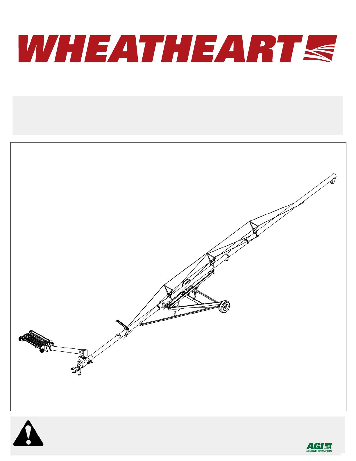
Read this manual before using product. Failure
SA AUGERS
SA 1061, 1071, 1081, 1091, 1371, 1381, 1391
OPERATION MANUAL
to follow instructions and safety precautions can
result in serious injury, death, or property
damage. Keep manual for future reference.
Part Number: 30582 R7
Revised: Aug/10

This product has been designed and constructed according to general engineering
standardsa. Other local regulations may apply and must be followed by the operator.
We strongly recommend that all personnel associated with this equipment be trained
in the correct operational and safety procedures required for this product. Periodic
reviews of this manual with all employees should be standard practice. For your
convenience, we include this sign-off sheet so you can record your periodic reviews.
Date Employee Signature Employer Signature
a. Standards include organizations such as the American Society of Agricultural and Biological Engineers,
American National Standards Institute, Canadian Standards Association, International Organization for
Standardization, and/or others.

WHEATHEART - SA AUGERS
SA 1061, 1071, 1081, 1091, 1371, 1381, 1391
TABLE OF CONTENTS
1. Introduction.......................................................................................................................... 5
2. Safety First............................................................................................................................ 7
2.1. General Safety ......................................................................................................... 8
2.2. Operating Safety ...................................................................................................... 9
2.3. Transport Safety..................................................................................................... 10
2.4. Storage Safety........................................................................................................ 10
2.5. Maintenance Safety................................................................................................ 10
2.6. Safety Decal Locations........................................................................................... 11
2.6.1. Decal Installation...................................................................................... 11
2.6.2. Decal Locations........................................................................................ 11
3. Transport & Placement...................................................................................................... 15
3.1. Transport Procedure .............................................................................................. 15
3.2. Placement Procedure............................................................................................. 17
4. Operation ............................................................................................................................ 19
4.1. Description of the Equipment................................................................................. 19
4.2. Operator Controls................................................................................................... 20
4.3. Pre-Operation......................................................................................................... 20
4.3.1. Checklist................................................................................................... 20
4.3.2. PTO Drive................................................................................................. 21
4.3.3. Hydraulics................................................................................................. 21
4.4. Operation Procedure.............................................................................................. 22
4.4.1. Initial Start-Up........................................................................................... 22
4.4.2. Normal Start ............................................................................................. 23
4.4.3. Normal Shutdown..................................................................................... 23
4.4.4. Emergency Stop / Full-Tube Restart ........................................................ 24
4.4.5. Lowering & Completion ............................................................................ 24
4.4.6. Power Swing / Hydraulic Winch Option.................................................... 24
30582 R7 3

WHEATHEART - SA AUGERS
SA 1061, 1071, 1081, 1091, 1371, 1381, 1391
TABLE OF CONTENTS
5. Maintenance........................................................................................................................ 27
5.1. Fluids and Lubricants ............................................................................................. 27
5.2. Maintenance Intervals ............................................................................................ 27
5.3. Maintenance Procedures........................................................................................ 28
5.3.1. Visual Inspection....................................................................................... 28
5.3.2. Hydraulic Hose and Coupler Inspection ................................................... 28
5.3.3. Machine Greasing..................................................................................... 29
5.3.4. Hopper Lift Cable Inspection .................................................................... 30
5.3.5. Winch and Pulley Servicing...................................................................... 30
5.3.6. Boot and Hopper Chain Drive Servicing................................................... 30
5.3.7. Gearbox Oil Level..................................................................................... 31
5.3.8. Machine Cleaning..................................................................................... 32
5.3.9. Tire Pressure Check................................................................................. 32
5.3.10. Wheel Bearings Repack......................................................................... 32
5.3.11. Wheel Bolt Tightening............................................................................. 32
5.3.12. Cable Tightening..................................................................................... 32
5.3.13. Gearbox Oil............................................................................................. 34
6. Storage................................................................................................................................ 35
7. Troubleshooting ................................................................................................................. 37
8. Appendix............................................................................................................................. 39
8.1. Specifications ......................................................................................................... 39
8.2. Bolt Torque Values ................................................................................................ 40
Warranty Registration.............................................................................................................. 43
Limited Warranty..................................................................................................................... 45
4 30582 R7
WHEATHEART - SA AUGERS 1. INTRODUCTION
SA 1061, 1071, 1081, 1091, 1371, 1381, 1391
1.Introduction
Congratulations on the purchase of your new Wheatheart SA Auger. This
equipment will complement your agricultural operation by safely and efficiently
moving grain, pulse crops, fertilizer, and any other granular materials.
Many of the features incorporated into this machine are the result of suggestions
made by customers like you. Your new Wheatheart auger will serve you well if
you understand how it operates, and if you use it and care for it properly. This
manual is intended to help you learn how to operate and maintain your
equipment in a safe, efficient, and trouble-free manner. Please read this manual
before you use your new grain auger .
This manual covers all SA augers built by Wheatheart Manufacturing. Use the
table of contents as a guide when searching for specific information. Keep this
manual in a safe place for future reference and for ordering replacement parts.
Should any information remain unclear after thoroughly reviewing this manual,
contact your Wheatheart Dealer for clarification before operating your auger.
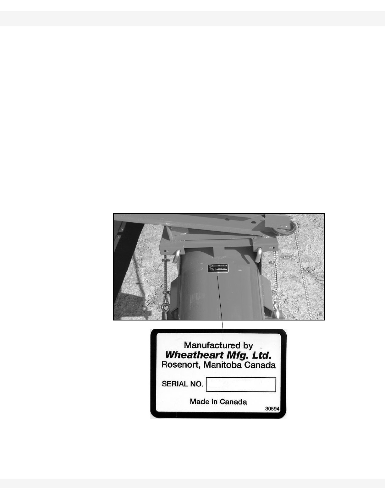
Knowing the serial number and date of purchase will save time in getting your
questions answered. Please write down this information in the space provided
below.
30582 R7 5

1. INTRODUCTION WHEATHEART - SA AUGERS
SA 1061, 1071, 1081, 1091, 1371, 1381, 1391
6 30582 R7
WHEATHEART - SA AUGERS 2. SAFETY FIRST
SA 1061, 1071, 1081, 1091, 1371, 1381, 1391
2.Safety First
The Safety Alert symbol to the left identifies important safety messages on the
product and in the manual. When you see this symbol, be alert to the possibility of personal injury or death. Follow the instructions in the safety messages.
Why is SAFETY important to you?
Three big reasons:
• Accidents disable and kill.
• Accidents cost.
• Accidents can be avoided.
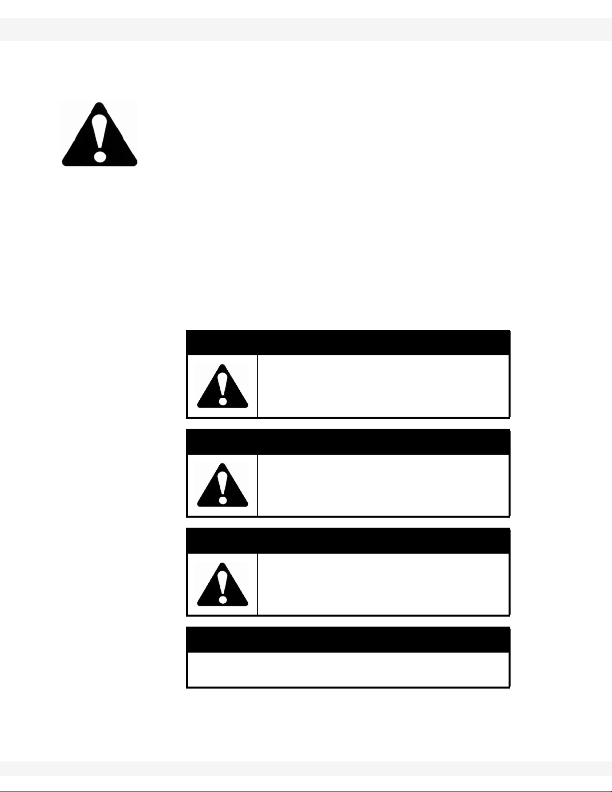
SIGNAL WORDS
Note the use of the signal words DANGER, WARNING, CAUTION, and NOTICE
with the safety messages. The appropriate signal word for each message has
been selected using the definitions below as a guideline.
The Safety Alert symbol means ATTENTION, BE ALERT!, YOUR SAFETY IS
INVOLVED.
DANGER
Indicates an imminently hazardous situation
that, if not avoided, will result in serious injury
or death.
WARNING
Indicates a hazardous situation that, if not
avoided, could result in serious injury or
death.
CAUTION
Indicates a hazardous situation that, if not
avoided, may result in minor or moderate
injury.
NOTICE
Indicates a potentially hazardous situation that, if not
avoided, may result in property damage.
30582 R7 7
2. SAFETY FIRST WHEATHEART - SA AUGERS
2.1. GENERAL SAFETY SA 1061, 1071, 1081, 1091, 1371, 1381, 1391
2.1. GENERAL SAFETY
Important: The general safety section includes instructions that apply to all safety practices.
Any instructions specific to a certain safety practice (e.g., assembly safety), can
be found in the appropriate section. Always read the complete instructional
sections and not just these safety summaries before doing anything with the
equipment.
YOU are responsible for the SAFE use and maintenance of your equipment.
YOU must ensure that you and anyone else who is going to work around the
equipment understands all procedures and related SAFETY information
contained in this manual.
Remember, YOU are the key to safety. Good safety practices not only protect
you, but also the people around you. Make these practices a working part of your
safety program.
• It is the equipment owner and the operator's responsibility to read and understand ALL safety instructions, safety decals, and manuals and follow them
before assembling, operating, or maintaining the equipment. All accidents
can be avoided.
• Equipment owners must give instructions and review the information initially
and anually with all personnel before allowing them to operate this product.
Untrained users/operators expose themselves and bystanders to possible
serious injury or death.
• Use this equipment for its intended purposes only.
• Do not modify the equipment in any way. Unauthorized modification may
impair the function and/or safety, and could affect the life of the equipment.
Any modification to the equipment voids the warranty.
• Do not allow children, spectators, or bystanders within the work area.
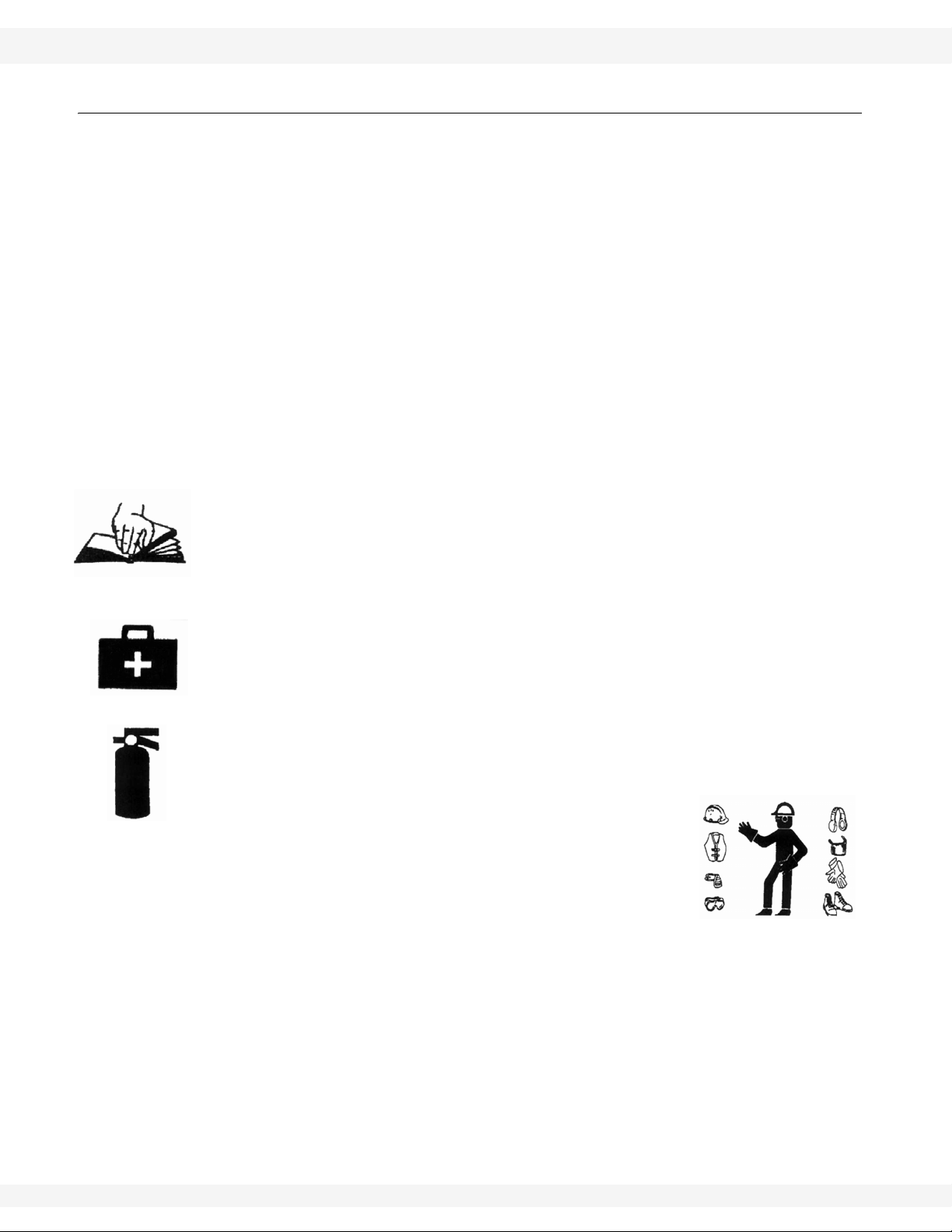
• Have a first-aid kit available for use should the need arise, and know how to
use it.
• Provide a fire extinguisher for use in case of an accident. Store in a highly visible place.
• Wear appropriate protective gear . This list includes, but
is not limited to:
• a hard hat
•gloves
• protective shoes with slip-resistant soles
• protective goggles
• hearing protection
• For Powered Equipment: before servicing, adjusting, or repairing powered
equipment, unplug, place all controls in neutral or off position, stop the engine
or motor , remove ignition key or lock out power source, and wait for all moving parts to stop.
8 30582 R7
WHEATHEART - SA AUGERS 2. SAFETY FIRST
Figure 2.1
SA 1061, 1071, 1081, 1091, 1371, 1381, 1391 2.2. OPERATING SAFETY
• Follow good shop practices:
• keep service area clean and dry
• be sure electrical outlets and tools are properly
grounded
• use adequate light for the job at hand
• Think SAFETY! Work SAFELY!
2.2. OPERATING SAFETY
• Ensure guards
are installed
and secure.
• Clear the work
area of
untrained people.
• Clean the
work area to
prevent slipping or tripping.
• Have a fully
equipped first
aid kit and fire
extinguisher
on hand and
know how to
use them.
• Be certain the
PTO driveline
is securely
attached to the
auger and to
the tractor.
• Before starting the tractor,
be certain that
the PTO is in
the off position.
• Keep hands,
feet, hair, and
clothing away
from all moving or rotating parts.
30582 R7 9

2. SAFETY FIRST WHEATHEART - SA AUGERS
2.3. TRANSPORT SAFETY SA 1061, 1071, 1081, 1091, 1371, 1381, 1391
2.3. TRANSPORT SAFETY
• Ensure tires are inflated to the tire manufacturer’s recommended pressure.
• Make sure that all lights and reflectors required by the local highway and
transport authorities are in place, are functioning, and can be seen clearly by
all overtaking and oncoming traffic.Check with local authorities regarding
transportation of agricultural equipment on public roads. Obey all applicable
laws and regulations.
• Be sure the unit is hitched securely to the towing vehicle.
• Do not allow riders while transporting.
• Display a Slow Moving Vehicle (SMV) emblem when transporting below 15
mph (24 km/h).
• Use hazard-warning flashers when transporting with a tractor unless prohibited.
• Keep to the right and yield the right-of-way to allow faster traffic to pass.
• Never transport faster than the road terrain or conditions will safely allow.
• Use caution when turning corners or meeting traffic.
• Use caution when approaching height-limiting objects.
• Be especially careful when transporting during times of limited visibility (rain,
snow, fog, dusk, or at night). If you can, wait for a more appropriate time to
move the equipment.
• Do not transport auger on a slope greater than 20°—the auger may overturn.
• The winch must be in the locked position. To lock, turn handle clockwise until
you hear two clicks. Also ensure that the locking pin and clips are in place on
the hopper lift arm.
2.4. STORAGE SAFETY
• Store in an area away from human activity.
• Do not permit children to play on or around the stored machine.
2.5. MAINTENANCE SAFETY
• Shut off and disable the power source before working on the machine.
• Ensure service area is clean and dry.
• Ensure electrical outlets and tools are properly grounded.
• Use proper tools for the job and wear appropriate safety gear.
• Ensure there is adequate lighting to perform the job safely.
• Place chocks in front and behind the wheels to prevent the machine from rolling.
• Use extra caution when cleaning and servicing augers because flighting
edges can be sharp.
• Follow proper procedures when mounting a tire on a rim. If in doubt, have a
qualified tire repair service perform the required maintenance.
• Install and secure all guards after maintenance work is completed.
10 30582 R7
WHEATHEART - SA AUGERS 2. SAFETY FIRST
DECAL #17100
SA 1061, 1071, 1081, 1091, 1371, 1381, 1391 2.6. SAFETY DECAL LOCATIONS
2.6. SAFETY DECAL LOCATIONS
• Keep safety decals clean and legible at all times.
• Replace safety decals that are missing or have become illegible. See decal
location figures that follow.
• Replaced parts must display the same decal(s) as the original part.
• Safety decals are available from your distributor, dealer, or factory.
2.6.1. DECAL INSTALLATION
1. Decal area must be clean and dry, with a temperature above 10°C (50°F).
2. Decide on the exact position before you remove the backing paper.
3. Align the decal over the specified area and carefully press the small portion
with the exposed sticky backing in place.
4. Slowly peel back the remaining paper and carefully smooth the remaining
portion of the decal in place.
5. Small air pockets can be pierced with a pin and smoothed out using the sign
backing paper.
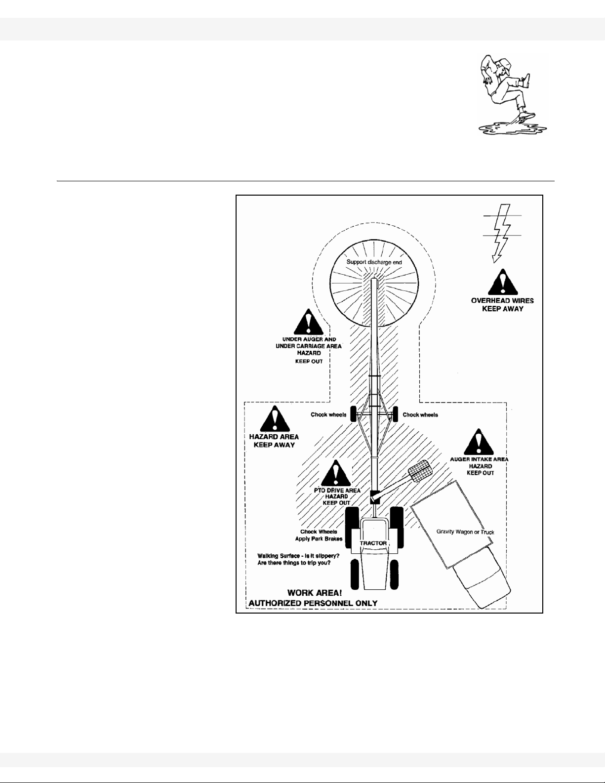
2.6.2. DECAL LOCATIONS
Replicas of the safety decals that are attached to the equipment are shown in the
figure(s) that follow. Good safety requires that you familiarize yourself with the
various safety decals and the areas or particular functions that the decals apply
to as well as the safety precautions that must be taken to avoid serious, injury,
death, or damage.
Figure 2.2
30582 R7 11
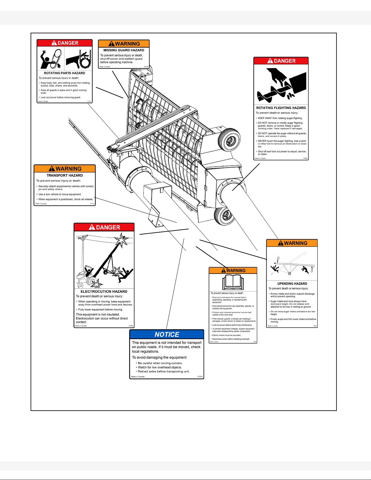
2. SAFETY FIRST WHEATHEART - SA AUGERS
DECAL #17098
DECAL #17097
DECAL #17096
DECAL #17398
DECAL #17101
DECAL #27709
DECAL #17113
DECAL # 17378
NOT INCLUDED ON SA1061
2.6. SAFETY DECAL LOCATIONS SA 1061, 1071, 1081, 1091, 1371, 1381, 1391
Figure 2.3
12 30582 R7
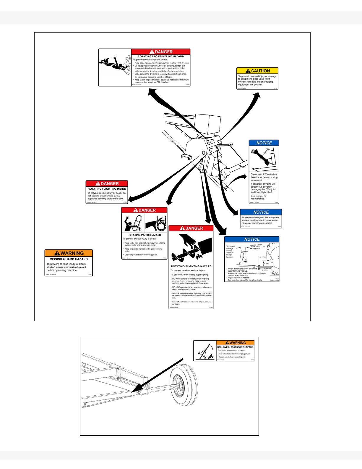
WHEATHEART - SA AUGERS 2. SAFETY FIRST
PLACED ON MACHINE
BEHIND GUARD
DECAL #17099
DECAL #17107
DECAL #18859
DECAL
#19960
DECAL
#17531
DECAL #17098
DECAL #17101
DECAL #27709
DECAL #17094
DECAL # 27516
SA 1061, 1071, 1081, 1091, 1371, 1381, 1391 2.6. SAFETY DECAL LOCATIONS
Figure 2.4
30582 R7 13
Figure 2.5 1081 / 1091 / 1371 / 1381 / 1391 Models Only

2. SAFETY FIRST WHEATHEART - SA AUGERS
2.6. SAFETY DECAL LOCATIONS SA 1061, 1071, 1081, 1091, 1371, 1381, 1391
14 30582 R7

WHEATHEART - SA AUGERS 3. TRANSPORT & PLACEMENT
Warning: Before continuing, please reread the safety information relevant to this section at
the beginning of this manual. Failure to follow the safety instructions can result in serious
injury, death, or property damage.
SA 1061, 1071, 1081, 1091, 1371, 1381, 1391 3.1. TRANSPORT PROCEDURE
3.Transport & Placement
DANGER
Electrocution hazard:
• This auger is not insulated.
• Keep auger away from overhead power
lines and devices.
• Electrocution can occur without direct
contact.
• Fully lower auger before moving.
Electrocution will result in serious injury or
death.
3.1. TRANSPORT PROCEDURE
The Wheatheart auger is designed to be easily and conveniently readied for
transport. Follow this procedure when converting the machine from operating to
transport configuration.
Empty the auger before transporting. Transporting a full
auger will place excessive loads on the tube assembly,
frame, axle assembly, hitch, and towing unit.
If auger wheels are partially or fully buried in snow or grain,
do not attempt to move auger until snow or grain has been
cleared away from auger wheels.
CAUTION
Failure to secure the unit prior to transporting
could cause a serious hazard to the
occupants of the towing vehicle or other
vehicles.
NOTICE
1. Reconnect the hydraulic hose couplers to the tractor if disconnected.
2. Place PTO driveline in the transport saddle and secure.
3. Remove all wheel chocks.
4. Raise the intake hopper off the ground.
5. Ensure the auger is clear of any obstructions before lowering.
30582 R7 15

3. TRANSPORT & PLACEMENT WHEATHEART - SA AUGERS
Figure 3.1 Transport Brace
Figure 3.2 Intake Hopper in Transport
Figure 3.3 Auger Chained to a Vehicle
3.1. TRANSPORT PROCEDURE SA 1061, 1071, 1081, 1091, 1371, 1381, 1391
6. Open the hose valve and then use the
tractor valve to lower the auger. Feather the
lever to prevent too rapid a descent. Lower
the auger until the transport brace is fully
seated (Figure 3.1).
7. Raise intake feed hopper into transport
position and secure with saddle pin and
hairpin (Figure 3.2).
a. Lock in transport position with the handle
on the side of the hopper.
b. Attach cable hook to the loops inside the
hopper.
c. Fully raise hopper with intake side
facing away from the main auger as
shown.
d. Secure hopper to lift arm with the
hopper lock, saddle pins, and hairpins
provided.Retract the wheels prior to
transporting (1081, 1091, and 13”
models only).
8. Install the safety chain between the auger and the frame of the towing unit.
Note:
The chain must have a load rating at
least as high as the auger weight.
a. Thread safety chain through the
auger hitch and bolt together
before attaching to the towing
vehicle. The loop should form a
cradle that will prevent the auger
from digging into the road surface
and upsetting it, should a
breakaway occur.
16 30582 R7
NOTICE
Transporting with axles extended may cause equipment
damage and may be in violation of local transport
regulations.

WHEATHEART - SA AUGERS 3. TRANSPORT & PLACEMENT
Figure 3.4 Wheel Extended
SA 1061, 1071, 1081, 1091, 1371, 1381, 1391 3.2. PLACEMENT PROCEDURE
b. Ensure there is no more slack in the chain than required for turning.
c. When not in use, store the safety chain in a clean, dry place. Replace the
safety chain if one or more links or end fittings are broken, stretched, or
otherwise damaged or deformed (Figure 3.3).
WARNING
Maximum transport speed:
Do not transport faster than 15 mph
(24 km/h), or faster than road conditions
allow.
A weight imbalance between the towing
vehicle and the machine could reduce your
vehicle’s stability, handling, and braking
ability, and lead to an upset or collision.
3.2. PLACEMENT PROCEDURE
Important: Wheels must be free to move when raising or lowering the auger.
1. Disconnect PTO driveline from tractor.
2. Position towing hitch and secure (Figure 3.5).
Important: Always use a safety chain when transporting the
auger.
3. Extend wheels (1081, 1091, and 13” models
only) as shown in Figure 3.4
4. Check that hydraulic hoses and connections are
undamaged and free from leaks.
Note: Replacement hose and hose ends must have a minimum strength of 2500 psi
30582 R7 17
Figure 3.5
(17200 kPa) working pressure.
5. Place the auger on a firm, level surface.

3. TRANSPORT & PLACEMENT WHEATHEART - SA AUGERS
3.2. PLACEMENT PROCEDURE SA 1061, 1071, 1081, 1091, 1371, 1381, 1391
Note: Do not place anything under the wheels of the auger for added height.
6. Check that the valve on the cylinder hose is open to raise the auger and
closed once the auger is in position.
CAUTION
If hose valve remains open, a loss of hydraulic
pressure within the tractor system will allow
the auger to lower inadvertently, damaging
equipment and/or causing personal injury.
7. Chock auger wheels on both sides and apply the tractor’s parking brake
before using the auger to move product (Figure 3.6).
8. When operating the auger in the raised position, rest the discharge end on
the bin roof or tie it down to the bin to prevent upending or the wind fromupsetting the auger. When operating the auger in a free-standing position,
anchor the intake end.
9. Fully lower the hopper to the ground and remove the lift cable from the
hopper.
Note: When raising or lowering the auger, the intake hopper must be lifted off the
ground.
Figure 3.6 Auger Placement
18 30582 R7

WHEATHEART - SA AUGERS 4. OPERATION
Warning: Before continuing, please reread the safety information relevant to this section at
the beginning of this manual. Failure to follow the safety instructions can result in serious
injury, death, or property damage.
SA 1061, 1071, 1081, 1091, 1371, 1381, 1391 4.1. DESCRIPTION OF THE EQUIPMENT
4.Operation
4.1. DESCRIPTION OF THE EQUIPMENT
Your auger comes field ready and equipped with such features as single acting
hydraulics, inward folding scissor lift for superior reach, a low profile hopper,
reinforced flighting in the hopper and incline tube, an enhanced grain pickup
system, left or right hand hopper operation, 6 bolt automotive hubs, handy
service access doors, and a constant velocity (CV) PTO shaft.
30582 R7 19

4. OPERATION WHEATHEART - SA AUGERS
Figure 4.1 Winch Location
Figure 4.2 Shut-off Valve
4.2. OPERATOR CONTROLS SA 1061, 1071, 1081, 1091, 1371, 1381, 1391
4.2. OPERATOR CONTROLS
The hopper winch is located as shown in Figure 4.1. The hydraulic shut-off valve
is located as shown in Figure 4.2. Please refer to the tractor manual for hydraulic
and PTO controls.
4.3. PRE-OPERATION
4.3.1. CHECKLIST
• Tighten all fasteners.
• Adjust and/or lubricate boot chain and hopper chain.
• Ensure auger rotates freely.
• Check that tire pressure is within the manufacturer’s specification.
• Ensure wheel bolt torque is within specification .
• Check hopper winch cable for damage (fraying, kinking, unraveling). Replace
as required.
• Ensure cable anchor on the winch drum is tight.
• Check gearbox oil levels.
• Grease and clean machine if needed.
• Ensure hydraulic system is functioning, is free of leaks, and the hoses are not
pinched or kinked.
• Check that truss cables are free from damage (fraying, kinking, unraveling).
The cables must be tight and properly adjusted for proper auger tube alignment.
• Ensure PTO shaft is properly installed.
20 30582 R7

WHEATHEART - SA AUGERS 4. OPERATION
SA 1061, 1071, 1081, 1091, 1371, 1381, 1391 4.3. PRE-OPERATION
4.3.2. PTO DRIVE
Correct operation of the Wheatheart SA auger requires pre-inspection of the
drive system, operator knowledge on how to shut down the system, and a
general monitoring of the system during operation.
GENERAL INFORMATION
Before starting the auger, ensure that:
• The PTO driveline is securely attached to the auger shaft and to the tractor.
• The PTO driveline rotating shield is in place and in good working order.
• The PTO does not exceed the maximum operating angle of 15°.
• All safety shields are in place and secure on both the tractor and the auger.
• The PTO drive on the tractor is in the off position before starting the tractor.
• The auger-to-tractor PTO hookup distances are set as specified in the decal
on the PTO shield of the auger.
• Everyone is clear of the PTO hazard area.
Note: If shear bolt in the PTO driveline fails, shut down and lock out the tractor to
replace the bolt. Use a 5/16” x 1” GR 8 bolt. Ensure the shear point is through
the shank of the bolt, not the threads.
LOCKOUT
1. Shut down the tractor and remove the ignition key or coil wire.
2. If step 1 is not possible, remove the PTO driveline from the tractor.
4.3.3. HYDRAULICS
Before using the hydraulics, ensure that:
• The quick connect couplers on both the auger and the tractor are clean and
free of dirt. Wipe the couplers with a clean, dry cloth.
• The hydraulic hoses are properly connected and secured; are free of leaks,
wear, and binding; and are routed away from moving parts.
• Hydraulic pressure has been relieved prior to disconnecting.
30582 R7 21

4. OPERATION WHEATHEART - SA AUGERS
4.4. OPERATION PROCEDURE SA 1061, 1071, 1081, 1091, 1371, 1381, 1391
4.4. OPERATION PROCEDURE
DANGER
Rotating Auger Hazard
Contact with rotating flighting will result in
amputation or severe laceration.
DO NOT operate with guards removed or
modified.
Keep hands and feet away from rotating
auger.
Tie up long hair and remove jewelry.
DO NOT wear loose-fitting clothing or items
that could become caught.
Shut off and lock out the power source before
unplugging or cleaning.
4.4.1. INITIAL START-UP
BREAK IN
Your auger does not require an elaborate break-in. However, following a few
simple tips during the initial operation can add to the reliability and life of your
machine.
If any unusual noises or vibrations are encountered, determine the source, shut
the auger off, lock out the power source, and adjust. If unsure of the problem or
procedure, contact your local Wheatheart dealer.
Important: When starting the auger for the first time, be prepared for an emergency
shutdown in case of excessive vibration or noise.
1. Ensure that you have completed the checklist on page 20.
2. If everything is satisfactory, prepare for a 60 minute operation at half speed.
3. Ensure that the intake hopper is correctly positioned.
4. Ensure that the PTO drive on the tractor is in the OFF position.
5. Start the tractor and idle at low rpm. Slowly engage the PTO drive.
Note: The auger may run rough until the tube is polished.
6. Gradually begin feeding grain into the hopper, bringing the auger speed up to
about 300 rpm. Do not overfeed the hopper on initial loads; keep the feed of
grain at about half capacity.
7. After the auger tube is polished and runs fairly smoothly, proceed to unload
at full speed of 540 rpm.
8. Upon completion of the initial run, slow the auger down. Stop the auger when
it is empty of grain.
22 30582 R7

WHEATHEART - SA AUGERS 4. OPERATION
SA 1061, 1071, 1081, 1091, 1371, 1381, 1391 4.4. OPERATION PROCEDURE
9. Lock out the tractor and conduct a complete inspection of the auger following
the checklist on page 20.
Important: After the initial start-up and inspection, the auger should be shut down and
inspected at least 3 more times during the first 10 hours of operation.
NOTICE
Do not run an empty auger at high speed; this results in
excessive wear.
4.4.2. NORMAL START
NOTICE
Foreign objects can damage the auger. Remove any
obstructions from the intake and discharge areas before
operating the unit.
1. Complete the checklist on page 20.
2. Place the intake hopper in its working position.
3. Make sure the PTO drive is in the off position when starting the tractor .
4. Engage the PTO with the tractor idling to prevent unneeded stress on the
drive components and shear bolts.
5. If everything is operating normally, start running grain through the auger and
bring the auger up to speed. Maintain a speed of 300–540 rpm for maximum
efficiency and to reduce the chance of plugging.
4.4.3. NORMAL SHUTDOWN
Prolonged operation of an empty auger will cause
unnecessary wear.
1. Near the end of the load, reduce the feed of grain and decrease the auger
speed where possible.
2. Run the auger until the tube is empty.
3. When the auger is clear of grain, disengage the PTO.
4. Shut down and lock out the power source.
NOTICE
30582 R7 23

4. OPERATION WHEATHEART - SA AUGERS
4.4. OPERATION PROCEDURE SA 1061, 1071, 1081, 1091, 1371, 1381, 1391
4.4.4. EMERGENCY STOP / FULL-TUBE RESTART
Although it is recommended that the machine be emptied before stopping, in an
emergency situation:
1. Stop or shut down the power source immediately.
2. Stop the flow of material (if applicable).
3. Correct the emergency before resuming work.
The tube may be filled with material if the machine is shut down inadvertently or
for an emergency. It is recommended that you restart with the following
procedure:
4. With the power source locked out, remove as much of the grain as possible
from the tube and intake using a piece of wood, vacuum cleaner, or other
tool. Do not use your hands.
5. Start the tractor and engage the PTO with the tractor idling.
NOTICE
Always engage PTO with tractor engine idling. Engaging
PTO at high engine speed will result in equipment damage.
6. Once the auger has been started, you may resume normal operation.
4.4.5. LOWERING & COMPLETION
1. Run the unit to clean out the majority of the grain.
2. Lock out the power source. Refer to page 21 for procedure.
3. Disconnect the PTO driveline and raise the hopper off the ground.
4. Remove all supports and chocks.
5. Move the auger out of working position and lower into transport position.
6. If necessary, open the cleanout door on the boot and manually clean out
grain using a piece of wood, vacuum cleaner, or other tool. Do not use your
hands. Replace the cleanout cover.
7. Lift the intake feed hopper into transport position and clean out the grain from
the hopper using a piece of wood, vacuum cleaner or other tool. Do not use
your hands.
4.4.6. POWER SWING / HYDRAULIC WINCH OPTION
The power swing/hydraulic winch option (Figure 4.3) uses a common control
valve (Figure 4.3) mounted to the intake hopper tube. Once the auger is raised
in the working position with the wheels chocked, remove the locking pin securing
the intake hopper to the hopper lift arm.
24 30582 R7

WHEATHEART - SA AUGERS 4. OPERATION
Figure 4.3 Power Swing/Hydraulic
Winch Option
Figure 4.3 Control Valve
SA 1061, 1071, 1081, 1091, 1371, 1381, 1391 4.4. OPERATION PROCEDURE
Ensure the area in the path of the intake hopper is unobstructed. Use the winch
control lever to lower the intake hopper to the ground. Unhook the winch cable
from the hopper. The intake hopper can now be positioned using the power
swing control lever. Traction can be controlled by adjusting the down pressure on
the power swing wheels using the jack.
30582 R7 25

4. OPERATION WHEATHEART - SA AUGERS
4.4. OPERATION PROCEDURE SA 1061, 1071, 1081, 1091, 1371, 1381, 1391
26 30582 R7

WHEATHEART - SA AUGERS 5. MAINTENANCE
Warning: Before continuing, please reread the safety information relevant to this section at
the beginning of this manual. Failure to follow the safety instructions can result in serious
injury, death, or property damage.
SA 1061, 1071, 1081, 1091, 1371, 1381, 1391 5.1. FLUIDS AND LUBRICANTS
5.Maintenance
NOTICE
Do not modify equipment.
Unauthorized modification may impair the function or safety
of the equipment, could affect the life of the equipment, and
will void your warranty.
5.1. FLUIDS AND LUBRICANTS
GEAR OIL
Use SAE approved 90W or equivalent gear oil.
GREASE
Use SAE multi-purpose high-temperature grease with extreme pressure (EP)
performance or SAE multi-purpose lithium-based grease.
5.2. MAINTENANCE INTERVALS
For details of service, refer to Section 5.3.
SECTION DAILY
(8000
BU)
VISUALLY INSPECT THE UNIT 5.3.1. Y Y
INSPECT HYDRAULIC HOSE
AND COUPLER
GREASE MACHINE 5.3.3. Y Y
INSPECT HOPPER LIFT
CABLE
SERVICE WINCH AND
PULLEYS
SERVICE BOOT AND HOPPER
CHAIN DRIVE
CHECK GEARBOX OIL LEVEL 5.3.7. Y
CLEAN MACHINE 5.3.8. Y
CHECK TIRE PRESSURE 5.3.9. Y Y
REPACK WHEEL BEARINGS 5.3.10. Y
TIGHTEN WHEEL BOLTS 5.3.11. Y
SERVICE TRUSS CABLES 5.3.12. Y
CHANGE GEARBOX OIL 5.3.13. Y
5.3.2. Y
5.3.4. Y
5.3.5. Y
• Y
30582 R7 27
PERIODICALLY
(40,000 BU)
BEFORE
STORAGE
AFTER
STORAGE
3-5 YEARS
(DEPENDING
ON USE)

5. MAINTENANCE WHEATHEART - SA AUGERS
5.3. MAINTENANCE PROCEDURES SA 1061, 1071, 1081, 1091, 1371, 1381, 1391
5.3. MAINTENANCE PROCEDURES
5.3.1. VISUAL INSPECTION
Before beginning visual inspection, check auger wheels and ensure that all
operators are awayre of safety procedures.
When inspecting, look for possible defects and for the following:
• Be sure all guards are in place, functioning, and not damaged.
• Make sure access, service, and cleanout covers are in place and secure.
• Check that all hardware is in place and secure.
• Inspect hydraulic hoses and fittings for leaks and wear. Fix or replace
where necessary.
• Inspect around the machine for evidence of hydraulic leaks.
• Examine flighting for damage or unusual wear.
• Inspect the truss cables for proper tension and possible damage such as
fraying, kinking, or unwinding.
• Inspect hopper winch cable for fraying, kinking, unwinding, or other possible damage.
• Examine tires for gashes, uneven wear, or loss of air pressure.
• Be sure all safety decals are in place and legible.
• Check the PTO shield & replace if damaged.
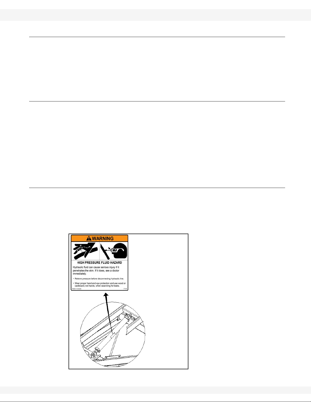
5.3.2. HYDRAULIC HOSE AND COUPLER INSPECTION
Using a piece of cardboard or wood, run it along the length of the hose and
around all fittings. Replace the hose or tighten/replace the fitting if a leak is
found.
WARNING
High-pressure hydraulic fluid!
Escaping oil under pressure can penetrate
the skin and cause serious injury.
• Relieve pressure on system before repairing, adjusting, or disconnecting.
• Keep connections tight and components
in good repair.
• Use a piece of wood or cardboard when
searching for leaks. DO NOT use your
hand.
• Seek medical attention immediately if
ANY hydraulic fluid penetrates your skin.
28 30582 R7

WHEATHEART - SA AUGERS 5. MAINTENANCE
SA 1061, 1071, 1081, 1091, 1371, 1381, 1391 5.3. MAINTENANCE PROCEDURES
5.3.3. MACHINE GREASING
Important: Most original equipment bearings used by Wheatheart are sealed units and will
not accept grease.
There are 8 grease fittings on the machine (shown in Figure 5.1):
• 1 at the upper flighting bearing (A)
• 3 on the intake hopper—2 bushings (B) and 1 at the U-joint (C)
• 1 at the u-joint between gearboxes (D)
• 1 at the lower flighting bearing (E)
• 5 on the PTO (F)
Figure 5.1 Grease Fitting Locations
To grease:
1. Use Use SAE multi-purpose high-temperature grease with extreme pressure
(EP) performance or SAE multi-purpose lithium-based grease.
2. Use a hand-held grease gun only.
3. Wipe grease fitting with a clean cloth before greasing to avoid injecting dirt
and grit.
4. If a fitting will not take grease, remove and clean thoroughly. Also clean
lubricant passageway. Replace fitting if necessary.
5. Replace and repair broken fittings immediately.
30582 R7 29

5. MAINTENANCE WHEATHEART - SA AUGERS
Figure 5.2 Cable Pulleys
5.3. MAINTENANCE PROCEDURES SA 1061, 1071, 1081, 1091, 1371, 1381, 1391
5.3.4. HOPPER LIFT CABLE INSPECTION
Check the cable for damage such as fraying, kinking, or unwinding. Replace if
damaged.
To replace:
1. Unwind the winch drum and remove the cable clamps.
2. Free the cable from the winch and pulleys.
3. Remove the cable clamps that secure the hook in place.
4. Reverse the above steps to install the new cable.
5.3.5. WINCH AND PULLEY SERVICING
• Ensure the cable is slack before
servicing the winch.
• Check to make sure cable clamps
are secure.
• Keep a film of grease on the gears.
Occasionally oil the bushings, drum
shaft, and ratchet.
• Oil cable pulleys needed (Figure
5.2)
5.3.6. BOOT AND HOPPER CHAIN DRIVE SERVICING
30 30582 R7
DANGER
Rotating parts hazard:
• Fingers, hands, feet, hair, clothing, and
accessories can become caught or drawn
into the pinch point.
• Shut off and disable power source before
adjusting or servicing.
• DO NOT operate with guards removed or
modified.
• Keep away from rotating parts.
• Tie up long hair and remove jewelry.
• DO NOT wear loose-fitting clothing or
items that could become caught.

WHEATHEART - SA AUGERS 5. MAINTENANCE
Figure 5.3 Boot Chain Drive
Note:
Figure 5.4 Hopper Chain Drive
Note:
Figure 5.5 Oil Filler Location
SA 1061, 1071, 1081, 1091, 1371, 1381, 1391 5.3. MAINTENANCE PROCEDURES
1. Remove chain cover plate from the boot or hopper.
2. Check chain slack.
• Chain slack is checked at the midpoint of the longest span. It should be no
more than 1/4” (6 mm).
Note: The Hopper has 2 chains, 1 for each flighting.
3. Adjust the chain slack.
a. For the Boot: loosen the 4 bolts of the lower
bearing and adjust the chain slack (Figure
5.3).
If the chain can’t be tightened enough, remove a
link from the chain. If the chain will not fit with one
link removed, add a half link to the chain and
replace.
b. For the Hopper: loosen the 2 bolts of the
flighting bearing on the side that needs
adjustment and set the chain slack (Figure
5.4).
If the chain can’t be tightened enough, remove a
link from the chain. If the chain will not fit with one
link removed, add a half link to the chain and
replace.
4. Lightly oil the chain.
Improper adjustment of chain will result in
premature wear.
5.3.7. GEARBOX OIL LEVEL
ACCESSING GEARBOX
Upper Gearbox
• Flip up safety discharge door or open
round service door and service gearbox
as required.
Lower Gearbox
NOTICE
CHECKING OIL LEVEL
1. Remove oil filler plug as shown in Figure
30582 R7 31
• Open round service door and service
gearbox as required.
5.5.

5. MAINTENANCE WHEATHEART - SA AUGERS
Figure 5.6 Crisscross Pattern
Note:
5.3. MAINTENANCE PROCEDURES SA 1061, 1071, 1081, 1091, 1371, 1381, 1391
2. Make sure the gearbox is half full (center of cross shaft) and free of foreign
objects. Gearbox should be level when checking or refilling. Do not overfill.
5.3.8. MACHINE CLEANING
1. Clean out excess grain from auger tube, boot, and hopper.
2. Make sure water can drain from the auger tube and hopper and then wash
the tube with a water hose or pressure washer until all dirt, mud, debris, or
residue is gone.
3. Provide sufficient time for the water to drain from the auger.
5.3.9. TIRE PRESSURE CHECK
With a tire pressure gauge, check each tire to make sure it is between 18–24 psi
(124 - 165 kPa).
• Ensure tires are cold prior to checking pressure.
5.3.10. WHEEL BEARINGS REPACK
1. Remove the wheel bolts and the wheels.
2. Remove the wheel bearing and pack with grease. Refer to page 27 for
recommended grease.
5.3.11. WHEEL BOLT TIGHTENING
1. Clean wheel and hub mounting
surfaces to ensure there is no rust or
debris.
1. Install the wheel and finger-tighten the
wheel bolts. Inspect to make sure the
wheel is sitting flush with the hub.
2. Tighten the wheel bolts with a torque
wrench to 80 ft-lb (±10 ft-lb) of torque.
Tighten the wheel bolts in a diagonal
pattern as shown in Figure 5.6.
5.3.12. CABLE TIGHTENING
The cables are properly adjusted when:
• The tube is straight side-to-side.
• The discharge end is deflected sightly upwards.
32 30582 R7

WHEATHEART - SA AUGERS 5. MAINTENANCE
Figure 5.7 Cable Adjustment
SA 1061, 1071, 1081, 1091, 1371, 1381, 1391 5.3. MAINTENANCE PROCEDURES
• There is no slack in the cables.
TIGHTENING CABLES
The location of the cable adjustment eyebolts are shown in Figure 5.7.
Note: The 1061 only has a long cable.
1. Lift the discharge end of the
auger with a front end
loader or rest on a bin so
that the tube has a slight
upward deflection at the
discharge to give the cable
some slack.
2. Tighten the nut on the
eyebolt to increase the
tension in the cable.
3. If the proper cable tension
can’t be obtained before the
eyebolt runs out of
adjustment, then do the
following:
a. Loosen the eyebolts but
do not remove the nut.
b. Loosen the clamps on the cable on both sides.
c. Shorten the cable until there is tension on the cable and tighten the
clamps.
d. Return to step 2.
STRAIGHTENING THE TUBE
1. If tube is not straight side-to-side:
• If the tube is curved to the left, tighten the right-hand eyebolt and loosen
the left-hand eyebolt on the long cable.
• If the tube is curved to the right, tighten the left-hand eyebolt and loosen
the right-hand eyebolt on the long cable.
• Check the short cable for slack and tighten as necessary.
• After adjusting the unit side-to-side, check that the tube still has a slight
upward deflection at the discharge.
2. If the tube is sagging at the discharge:
• Lift the discharge end of the auger with a front end loader or rest on a bin
so that the tube has a slight upward deflection at the discharge to give the
cable some slack.
• Tighten the long cable’s eyebolts evenly on both sides so the tube stays
straight.
• Tighten the cables so there is a slight upwards angle on the discharge
end.
• Check the short cable for slack and tighten as necessary.
30582 R7 33

5. MAINTENANCE WHEATHEART - SA AUGERS
5.3. MAINTENANCE PROCEDURES SA 1061, 1071, 1081, 1091, 1371, 1381, 1391
5.3.13. GEARBOX OIL
1. Place a pan under the drain plug.
2. Use a wrench and remove the drain plug.
3. Loosen the filler plug so air can enter the gearbox and the oil will drain freely
(see Figure 5.5).
4. Allow the oil to drain completely.
5. Replace the drain plug.
6. Add oil until the gearbox is half full (center of cross shaft) and replace filler
plug. A flexible funnel may be required. Gearbox should be level when
checking or refilling. Do not overfill.
For more extensive servicing or repairs, remove the hopper from the boot
assembly by removing the 3/8” x 3/4” bolts and large washers. Lift the gearbox
end with a front end loader or other secure method as shown in Figure 5.8. The
hopper end should remain on the ground. When reassembling, lightly grease the
splined shaft and check and retighten setscrews and connecting bolts.
Figure 5.8 Hopper Tube Removal
34 30582 R7

WHEATHEART - SA AUGERS 6. STORAGE
Warning: Before continuing, please reread the safety information relevant to this section at
the beginning of this manual. Failure to follow the safety instructions can result in serious
injury, death, or property damage.
SA 1061, 1071, 1081, 1091, 1371, 1381, 1391
6.Storage
WARNING
To reduce the risk of injury or death, store in
an area away from human activity and do not
permit children to play on or around the stored
machine.
To ensure a long, trouble-free life, the following procedure should be followed
when preparing the unit for storage after the season’s use:
1. Fully lower the auger.
2. Remove all residual material from the auger.
3. Remove entangled material from all moving or rotating parts.
4. Wash the entire machine thoroughly using a water hose or pressure washer
to remove all dirt, mud, debris, and residue.
5. Repair or replace any worn or damaged components to prevent any
unnecessary downtime at the start of the next season.
6. Touch up all paint nicks and scratches to prevent rusting.
7. Position the auger in an area that is dry, level, free of debris, and away from
human activity.
8. Support the hitch on blocks to eliminate prolonged contact with the ground.
9. Lubricate all grease fittings (see page 29).
10. Clean and lightly lubricate the spline on the PTO driveline. Cover the PTO
driveline with a plastic bag to protect it from the weather and place it in the
transport saddle.
11. Check tire pressure and inflate to 24 psi (165 kPa).
12. Chock the wheels.
13. Place the hopper in transport position, ensuring there will be adequate
drainage of any moisture.
30582 R7 35

6. STORAGE WHEATHEART - SA AUGERS
SA 1061, 1071, 1081, 1091, 1371, 1381, 1391
36 30582 R7

WHEATHEART - SA AUGERS 7. TROUBLESHOOTING
SA 1061, 1071, 1081, 1091, 1371, 1381, 1391
7.Troubleshooting
The following table lists the causes and solutions to some potential problems you
may encounter in operating your swing-away auger.
Table 7.1
PROBLEM CAUSED BY SOLUTION
Auger is plugged or obstructed. Identify and remove obstruction.
A bearing has seized. Iden tify the be a rin g an d re pla ce .
The auger does not
turn.
The upper auger sections will not turn.
Auger is noisy.
The auger will not raise
or lower.
Low material augering
rate.
Auger will not stay in
elevated position.
Tube is misaligned. Loose truss cables. Tighten cables as required.
A chain is broken. Identify the chain and repair or replace.
The gearbox has seized. Fix or replace the gearbox.
Gearbox coupler bolt is broken or
missing.
PTO shear bolt has failed. Replace the bolt.
The coupler bolt below the non-
rotating section is broken or missing.
Obstruction in the auger. Identify and remove obstruction.
Flighting shaft bolts are loose or
damaged.
Auger shaft is bent. Repair or replace shaft.
Flighting is damaged. Repair or replace flighting.
Worn bearing. Repair or replace bearing.
Low gear oil level.
Tube is misaligned. Adjust truss cables.
Closed hydraulic valve. Open hydraulic valve.
Inadequate hydraulic pressure.
Damaged cylinder. Fix or replace the cylinder.
Missing or broken cylinder pin. Replace cylinder pin.
Hydraulic system leak. Identify and repair leak.
Auger movement is obstructed. Identify and clear the obstruction.
Tractor PTO speed is too slow. Increase engine rpm.
Inadequate material flow from truck
or hopper.
Flow into the auger hopper is
restricted.
Material is too wet or heavy. Unloading rates are for dry grain.
Flighting is worn. Repair or replace as required.
Leak in auger hydraulic cylinder or
fittings.
Leak in tractor hydraulics.
Replace the bolt.
Replace the bolt.
Tighten or replace bolts.
Inspect the gearbox and repair or replace if
damaged. If no damage is found, add oil to
gearbox.
Adjust the pressure if possible, or use an alternate hydraulic supply.
Increase flow of material.
Clear grating of obstructions.
Identify and repair leak.
Close hydraulic valve to isolate cylinder from
tractor hydraulics.
30582 R7 37

7. TROUBLESHOOTING WHEATHEART - SA AUGERS
SA 1061, 1071, 1081, 1091, 1371, 1381, 1391
38 30582 R7

WHEATHEART - SA AUGERS 8. APPENDIX
SA 1061, 1071, 1081, 1091, 1371, 1381, 1391 8.1. SPECIFICATIONS
8.Appendix
8.1. SPECIFICATIONS
Important: Wheatheart Manufacturing reserves the right to change specifications without
notice.
Table 8.1
1061 1071 1081 1091 1371 1381 1391
CAPACITy
Unloading Rate 5400 - 6000 Bu/Hr 8700 - 9600 Bu/Hr
DIMENSIONS
Tube Size 10” 10” 10” 10” 13” 13” 13”
Length 63’5” 73’6” - - - - -
Transport
Discharge
Clearance
Reach to
Wheels
Type Type 15” Bias Ply 16” Bias Ply
Inflation Pressure 18 – 24 psi
Hubs 6 Bolt Automotive Type
Total Weight 3100 lb 3410 lb 3980 lb 5010 lb 4915 lb 5550 lb
Power Requirements 60 HP 65 HP 80 HP 90 HP 100 HP 120 HP 140 HP
PTO Speed 540 rpm
PTO Shaft 14R Constant Velocity w/ Shear 35R
Hitch Jack 2000 lb Side Winder
Width 11’ 11’ 11’8” / 15’ 1 1’8” / 15’ 11’8” / 15’ 11’8” / 15’ 11’8” / 15’
Height 12’11” 12’11” 13’6” 13’6” 12’1” 11’8” 12’4”
Min 11’ 11’ 11’6” 11’7” 9’9” 9’3” 9’11”
Max 41’1” 47’ 52’6” 58’6” 49’ 53’9” 61’3”
Min 23’5” 26’10” 29’2” 35’5” 26’9” 29’1” 30’1”
Max 29’6” 34’2” 39’3” 45’ 35’9” 42’ 45’2”
TIRES
WEIGHT
6745 lb
est.
PTO DRIVE
OTHER
30582 R7 39

8. APPENDIX WHEATHEART - SA AUGERS
8.2. BOLT TORQUE VALUES SA 1061, 1071, 1081, 1091, 1371, 1381, 1391
8.2. BOLT TORQUE VALUES
The tables shown below give correct torque values for various bolts and
capscrews. Tighten all bolts to the torque specified in the chart unless otherwise
noted. Check tightness of bolts periodically , using bolt torque chart as your guide.
Replace hardware with the same strength bolt.
Table 8.2 Imperial Bolt Torque
BOLT
DIAMETER
1/4" 8 6 12 9 17 12
5/16" 13 10 25 19 36 27
3/8" 27 20 45 33 63 45
7/16" 41 30 72 53 100 75
1/2" 61 45 110 80 155 115
9/16" 95 60 155 115 220 165
5/8" 128 95 215 160 305 220
3/4" 225 165 390 290 540 400
7/8" 230 170 570 420 880 650
1" 345 225 850 630 1320 970
(Nm) (Lb-ft) (Nm) (Lb-ft) (Nm) (Lb-ft)
Figure 8.1 Criss-Cross Pattern for Wheel Bolts
Torque figures indicated above are valid for non-greased or non-oiled threads
and head unless otherwise specified. Therefore, do not grease or oil bolts or
capscrews unless otherwise specified in this manual. When using locking
elements, increase torque values by 5%.
40 30582 R7

WHEATHEART - SA AUGERS 8. APPENDIX
SA 1061, 1071, 1081, 1091, 1371, 1381, 1391 8.2. BOLT TORQUE VALUES
Table 8.3 Metric Bolt Torque
BOLT DIAMETER
M3 0.5 0.4 1.8 1.3
M4 3 2.2 4.5 3.3
M5 6 4 9 7
M6 10 7 15 11
M8 25 18 35 26
M10 50 37 70 52
M12 90 66 125 92
M14 140 103 200 148
M16 225 166 310 229
M20 435 321 610 450
M24 750 553 1050 774
M30 1495 1103 2100 1550
M36 2600 1917 3675 2710
(Nm) (Lb-ft) (Nm) (Lb-ft)
30582 R7 41

8. APPENDIX WHEATHEART - SA AUGERS
8.2. BOLT TORQUE VALUES SA 1061, 1071, 1081, 1091, 1371, 1381, 1391
42 30582 R7

WARRANTY REGISTRATION
Wheatheart congratulates you on your new equipment purchase.
The warranty registration form must be filled out within thirty (30) days from delivery date and sent to:
Wheatheart Manufacturing
Box 39 Rosenort, Manitoba, Canada, R0G 1WO
CUSTOMER COPY
(Retain this card for warranty and record purposes.)
PRODUCT: DEALER’S NAME:
SERIAL #:
DELIVERY DATE:
OWNER’S NAME: PHONE #:
ADDRESS:
PHONE #:
DEALER COPY
(Retain this card for warranty and record purposes.)
PRODUCT: DEALER’S NAME:
SERIAL #:
DELIVERY DATE:
OWNER’S NAME: PHONE #:
ADDRESS:
PHONE #:
ADDRESS:
SIGNATURE:
INVOICE #:
(Please refer to invoice # when filing claim)
ADDRESS:
SIGNATURE:
INVOICE #:
(Please refer to invoice # when filing claim)
WARRANTY REGISTRATION
(Must be filled out and returned to Wheatheart within 30 days of delivery.)
OWNER’S NAME: DEALER’S NAME:
ADDRESS:
PHONE #: PHONE #:
SIGNATURE:
(I acknowledge the product to be whole and in
proper working order.)
PRODUCT: SERIAL #:
INVOICE #:
ADDRESS:
SIGNATURE:
(I acknowledge the product to be whole and in
proper working order. The owner has been given
an operation manual and has been informed on
proper operation and maintenance.)
DELIVERY DATE:
GAS MOTOR SERIAL #:


LIMITED WARRANTY
Wheatheart warrants to the buyer that the new machinery is free from defects in material and
workmanship.
This warranty is only effective for any new machinery that has not been altered, changed,
repaired, or treated since its delivery to the buyer, other than by Wheatheart or its authorized
dealers or employees, and does not apply to accessories, attachments, tools, or parts sold or
operated with the new machinery if they have not been manufactured by Wheatheart.
Wheatheart shall only be liable for defects in the material or workmanship attributed to faulty
material or bad workmanship that can be proved by the buyer, and specifically excludes liability
for repairs arising as a result of normal wear and tear of the new machinery or in any other manner whatsoever, and without limiting the generality of the foregoing, excludes application or
installation of parts not completed in accordance with Wheatheart operation manual, specifications, or printed instructions.
A Warranty Registration Form and Inspection Report must be completed at the time of delivery
and returned to Wheatheart Manufacturing within thirty (30) days.
Warranty Period
Private Farm Use One (1) year from date of purchase.
Commercial, Custom, or Rental Use Ninety (90) days from date of purchase.
Replacement Parts Ninety (90) days from date of replacement
Defective parts are subject to inspection by a Wheatheart representative prior to approval of a
warranty claim. All returned parts must be sent to the factory, freight pre-paid, in order to qualify
for warranty replacement. Repaired or replaced parts will be returned freight collect.
If these conditions are fulfilled, Wheatheart shall at its own cost and its own option either repair
or replace any defective parts provided that the buyer shall be responsible for all expenses
incurred as a result of repairs, labor , part s, transporta tion, or any other work, unless Wheatheart
has authorized such expenses in advance. Normal wear and service items such as belts,
hoses, flashing, etc. are excluded from warranty.
The warranty shall not extend to any repairs, changes, alterations, or replacements made to the
new equipment other than by Wheatheart or its authorized dealers or employees.
This warranty extends only to the original owner of the new equipment.
This warranty is limited to the terms stated herein and is in lieu of any other warranties whether
expressed or implied, and without limiting the generality of the foregoing, excluded all warranties, expressed or implied, or conditions whether statutory or otherwise as to quality and fitness
for any purpose of the new equipment, Wheatheart disclaims all liability for incidental or consequential damages.
This machine is subject to design changes and Wheatheart shall not be required to retro-fit or
exchange items on previously sold units except at its own option.
WARRANTY VOID IF NOT REGISTERED

Wheatheart
Part of the Ag Growth International Inc. Group
P.O. Box 39
Rosenort, Manitoba, Canada R0G 1W0
Phone: (866) 467-7207 (Canada & USA)
Fax: (866) 768-4852
website: www.wheatheart.com
email: sales@wheatheart.ca
© Ag Growth International Inc. 2013
Printed In Canada
 Loading...