


Read this manual before using product. Failure
SELF-PROPELLED POST
POUNDER KIT
TRAILER POST POUNDER MODEL
INSTALLATION & OPERATION MANUAL
to follow instructions and safety precautions can
result in serious injury, death, or property
damage. Keep manual for future reference.
Part Number: IM12 R3
Revised: Nov/12

This product has been designed and constructed according to general engineering
standardsa. Other local regulations may apply and must be followed by the operator.
We strongly recommend that all personnel associated with this equipment be trained
in the correct operational and safety procedures required for this product. Periodic
reviews of this manual with all employees should be standard practice. For your
convenience, we include this sign-off sheet so you can record your periodic reviews.
Date Employee Signature Employer Signature
a. Standards include organizations such as the American Society of Agricultural and Biological Engineers,
American National Standards Institute, Canadian Standards Association, International Organization for
Standardization, and/or others.

WHEATHEART - SELF-PROPELLED POST POUNDER KIT
TRAILER POST POUNDER MODEL
TABLE OF CONTENTS
1. Introduction.......................................................................................................................... 5
1.1. Purpose of the Equipment........................................................................................ 6
2. Safety .................................................................................................................................... 7
2.1. General Safety ......................................................................................................... 8
2.2. Installation Safety..................................................................................................... 8
2.3. Operation Safety ...................................................................................................... 9
2.4. Transport Safety..................................................................................................... 11
2.5. Hydraulic Safety..................................................................................................... 11
2.6. Safety Decals......................................................................................................... 12
2.6.1. Decal Installation...................................................................................... 12
2.6.2. Safety Decal Locations............................................................................. 12
3. Operation ............................................................................................................................ 15
3.1. Placement & Operation Procedure......................................................................... 15
3.2. Transport Preparation ............................................................................................ 17
4. Installation .......................................................................................................................... 19
4.1. Ring Gears............................................................................................................. 19
4.2. Wheel Drives.......................................................................................................... 19
4.3. Front Wheel Assembly........................................................................................... 22
4.4. Spike Installation.................................................................................................... 23
4.5. Valve and Valve Mount .......................................................................................... 24
4.6. Oil Reservoir........................................................................................................... 25
4.7. Hydraulics............................................................................................................... 26
5. Appendix............................................................................................................................. 27
5.1. SP Pounder Parts................................................................................................... 27
5.2. Hydraulics Parts..................................................................................................... 31
5.2.1. SP Pounder Hydraulics With Pilot Auger.................................................. 31
5.2.2. SP Pounder Hydraulics Without Pilot Auger............................................. 33
Limited Warranty..................................................................................................................... 35
IM12 R3 3

WHEATHEART - SELF-PROPELLED POST POUNDER KIT
TRAILER POST POUNDER MODEL
4 IM12 R3

WHEATHEART - SELF-PROPELLED POST POUNDER KIT 1. INTRODUCTION
TRAILER POST POUNDER MODEL
1.Introduction
Thank you for purchasing a Wheatheart Self-Propelled Post Pounder Kit. This
equipment is intended for the installation of fence posts, and will allow you to
perform your work safely and efficiently when you read and follow all of the
instructions contained in this manual. With proper care, your Self-Propelled Post
Pounder Kit will provide you with many years of trouble-free service.
Keep this manual handy for frequent reference and to review with new
personnel. A sign-off form is provided on the inside front cover for your convenience. Call your local distributor or dealer if you need assistance or additional
information.
This manual should be regarded as part of the equipment. Suppliers of both new
and second-hand equipment are advised to retain documentary evidence that
this manual was provided with the machine.
Important: This is a supplemental manual which contains additional information about how
to operate a Self-Propelled Post Pounder Kit and is not a substitute for the Post
Pounder Operator Manual. An operator is not considered trained on how to
operate a Self-Propelled Post Pounder Kit unless they have read and understood
this manual and the Post Pounder Operator Manual.
IM12 R3 5

1. INTRODUCTION WHEATHEART - SELF-PROPELLED POST POUNDER KIT
1.1. PURPOSE OF THE EQUIPMENT TRAILER POST POUNDER MODEL
1.1. PURPOSE OF THE EQUIPMENT
The Self-Propelled Post Pounder Kit is designed and manufactured for the
efficient installation of fence posts. Before operating near power lines or buried
gas lines, consult local utility companies. Ensure all support legs are secured on
the ground before operating. Use only a tractor, towing vehicle or skid steer
loader of adequate power and capacity to operate the machine. Use in any other
way is considered as contrary to the intended use.
The following are unacceptable misuses of the Self-Propelled Post Pounder Kit.
Damage caused by such misuse is not covered by warranty. When operating or
maintaining the Self-Propelled Post Pounder Kit, NEVER:
• let impact head free fall without pounding a post, if head must be lowered,
shut off and lock out power source and gently actuate hydraulic valve.
• use the hugger to straighten crooked post.
• use hands to isolate and identify leak.
• position a foot under the machine.
• transport without fully retracting the pounder mast head.
• modify the equipment.
This equipment should be operated, serviced, and repaired only by persons who
are familiar with its particular characteristics and who are acquainted with the
relevant safety procedures. Any arbitrary modifications carried out on this
equipment may relieve the manufacturer of liability for any resulting damage or
injury.
6 IM12 R3
WHEATHEART - SELF-PROPELLED POST POUNDER KIT 2. SAFETY
TRAILER POST POUNDER MODEL
2.Safety
The Safety Alert symbol to the left identifies important safety messages on the
product and in the manual. When you see this symbol, be alert to the possibility of personal injury or death. Follow the instructions in the safety messages.
Why is SAFETY important to you?
• Accidents disable and kill.
• Accidents cost.
• Accidents can be avoided.
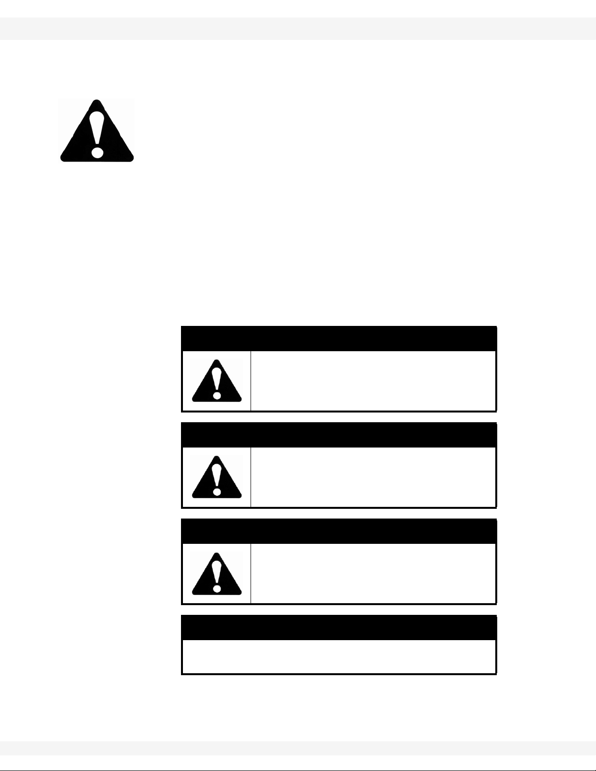
SIGNAL WORDS
Note the use of the signal words DANGER, WARNING, CAUTION, and NOTICE
with the safety messages. The appropriate signal word for each message has
been selected using the definitions below as a guideline.
The Safety Alert symbol means: “ATTENTION, BE ALERT! YOUR SAFETY IS
INVOLVED”.
DANGER
Indicates an imminently hazardous situation
that, if not avoided, will result in serious injury
or death.
WARNING
Indicates a hazardous situation that, if not
avoided, could result in serious injury or
death.
CAUTION
Indicates a hazardous situation that, if not
avoided, may result in minor or moderate
injury.
NOTICE
Indicates a potentially hazardous situation that, if not
avoided, may result in property damage.
IM12 R3 7

2. SAFETY WHEATHEART - SELF-PROPELLED POST POUNDER KIT
2.1. GENERAL SAFETY TRAILER POST POUNDER MODEL
2.1. GENERAL SAFETY
Important: This general safety section includes instructions that apply to all safety practices.
Any instructions specific to a certain safety practice (e.g., Operational Safety),
can be found in the appropriate section. Always read the complete instructional
sections and not just these safety summaries before doing anything with the
equipment.
YOU are responsible for the SAFE use and maintenance of your equipment.
YOU must ensure that you and anyone else who is going to work around the
equipment understands all procedures and related SAFETY information
contained in this manual.
Remember, YOU are the key to safety. Good safety practices not only protect
you, but also the people around you. Make these practices a working part of your
safety program.
• It is the equipment owner, operator, and maintenance personnel's responsibility to read and understand ALL safety instructions, safety decals, and manuals and follow them when assembling, operating, or maintaining the
equipment. All accidents can be avoided.
• Equipment owners must give instructions and review the information initially
and annually with all personnel before allowing them to operate this product.
Untrained users/operators expose themselves and bystanders to possible
serious injury or death.
• Use this equipment for its intended purposes only.
• Do not modify the equipment in any way without written permission from the
manufacturer. Unauthorized modification may impair the function and/or
safety, and could affect the life of the equipment. Any unauthorized modification of the equipment voids the warranty.
• Do not allow any unauthorized person in the work area.
2.2. INSTALLATION SAFETY
1. Read and understand all safety instructions and all safety decals before
starting.
2. Follow good shop practices.
• Use properly sized tools, stands, jacks and hoists at all times.
• Be sure electrical outlets and tools are properly grounded.
• Use adequate light for the job at hand.
• Use 2 people to handle the heavy bulky components.
• Keep the assembly area neat and clean to prevent slipping or tripping.
• Place safety stands or large blocks under the machine or components
before going beneath the component for assembly
3. Stay away from overhead power lines and obstructions when lifting the
machine during assembly . Contact with power lines can cause electrocution.
Contact with obstructions can damage components or cause them to fail.
4. Tighten all fasteners to their specified torque before using the machine (See
“Specifications & Drive Options” on page 42).
8 IM12 R3

WHEATHEART - SELF-PROPELLED POST POUNDER KIT 2. SAFETY
TRAILER POST POUNDER MODEL 2.3. OPERATION SAFETY
2.3. OPERATION SAFETY
In addition to the information provided in the standard Post Pounder manual:
• Only stand behind the controls when operating the self-propelled pounder .
• Chock wheels or lower spike to prevent machine from rolling and to
improve stability.
• Be careful when backing up machine.
• Ensure that your hands are clear of the hugger. Do not hold post in place
while trying to adjust machine position.
• Keep away from spike while operating.
• Hitch must be fully retracted, placing the spike further back from the frame
and making it less likely to penetrate a foot.
• Keep away from wheel arm while operating.
• Do not operate machine without wheel arm pin in place.
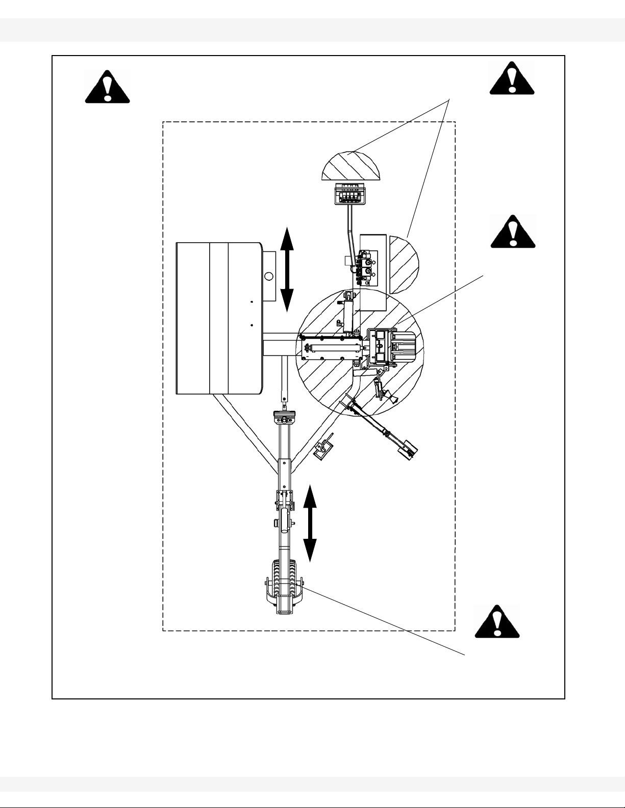
• Review the work safety area diagram (Figure 2.1) before using this equipment.
IM12 R3 9
2. SAFETY WHEATHEART - SELF-PROPELLED POST POUNDER KIT
OPERATOR ONLY AT
CONTROLS!
FLYING DEBRIS
HAZARD
CRUSHING ZONE!
KEEP CLEAR
CRUSHING
HAZARD!
WORK AREA!
TRAINED PERSONNEL ONLY!
2.3. OPERATION SAFETY TRAILER POST POUNDER MODEL
Figure 2.1 Work Safety Area
10 IM12 R3
WHEATHEART - SELF-PROPELLED POST POUNDER KIT 2. SAFETY
TRAILER POST POUNDER MODEL 2.4. TRANSPORT SAFETY
2.4. TRANSPORT SAFETY
In addition to the information in the standard post pounder manual:
• Lower spike or chock wheels to reduce risk of machine rolling and to improve
stability when attaching it to a tow vehicle.
• Raise spike and secure cylinder lock when transporting.
• Ensure jack is in transport position when towing machine.
• Review the work safety area diagram (Figure 2.1) before transporting.
2.5. HYDRAULIC SAFETY
• Always place all hydraulic controls in neutral and relieve system pressure
before disconnecting or working on hydraulic system.
• Keep all components in the hydraulic system tightly secured, clean and in
good condition.
• Replace any worn, cut, abraded, flattened, or crimped hoses.
• Do not attempt any makeshift repairs to the hydraulic fittings or hoses with
tape, clamps, or adhesive. The hydraulic system operates under extremely
high pressure; such repairs will fail suddenly and create a hazardous and
unsafe condition.
• Before moving a hydraulic cylinder, ensure that the attached component is
safely secured.
WARNING
Hydraulic fluid can cause serious injury if it
penetrates the skin. If it does, see a doctor
immediately.
• Relieve pressure before disconnecting
hydraulic line.
• Wear proper hand and eye protection and
use wood or cardboard, not hands, when
searching for leaks.
IM12 R3 11

2. SAFETY WHEATHEART - SELF-PROPELLED POST POUNDER KIT
2.6. SAFETY DECALS TRAILER POST POUNDER MODEL
2.6. SAFETY DECALS
• Keep safety decals clean and legible at all times.
• Replace safety decals that are missing or have become illegible. See decal
location figures that follow.
• Replaced parts must display the same decal(s) as the original part.
• Safety decals are available from your distributor, dealer, or factory.
2.6.1. DECAL INSTALLATION
1. Decal area must be clean and dry, with a temperature above 50°F (10°C).
2. Decide on the exact position before you remove the backing paper.
3. Align the decal over the specified area and carefully press the small portion
with the exposed sticky backing in place.
4. Slowly peel back the remaining paper and carefully smooth the remaining
portion of the decal in place.
5. Small air pockets can be pierced with a pin and smoothed out using the sign
backing paper.
2.6.2. SAFETY DECAL LOCATIONS
Replicas of the safety decals that are attached to the equipment are shown in the
figure(s) that follow. Proper safety procedures require that you familiarize
yourself with the various safety decals and the areas or particular functions that
the decals apply to, as well as the safety precautions that must be taken to avoid
serious injury, death, or damage.
12 IM12 R3

WHEATHEART - SELF-PROPELLED POST POUNDER KIT 2. SAFETY
WARNING NOTICE
RUN-OVER HAZARD
To prevent injury:
• Lower spike or chock wheels to
prevent machine from rolling.
• Be careful when backing up
machine.
To prevent damage:
• Secure handle in chain lock before
towing.
• When pounding posts, lower spike
to stabilize machine.
9700083
TURN
REVERSE
SPIKE
ENGAGED
DRIVE WHEELS
TURN
TO
RAISE
LEVER
FORWARD
BOTH
ENGAGED
SINGLE
LEVERS
LOWER
TO
ENGAGED
SINGLE
LEVER
BOTH
LEVERS
ENGAGED
TRAILER POST POUNDER MODEL 2.6. SAFETY DECALS
Figure 2.2 Safety Decal Locations
IM12 R3 13

2. SAFETY WHEATHEART - SELF-PROPELLED POST POUNDER KIT
2.6. SAFETY DECALS TRAILER POST POUNDER MODEL
14 IM12 R3

WHEATHEART - SELF-PROPELLED POST POUNDER KIT 3. OPERATION
Warning: Before continuing, ensure you have read and understand the relevant information
in the safety section. Safety information is provided to help prevent serious injury, death, or
property damage.
Figure 3.1
Note:
TRAILER POST POUNDER MODEL 3.1. PLACEMENT & OPERATION PROCEDURE
3.Operation
3.1. PLACEMENT & OPERATION PROCEDURE
Note: All control functions are illustrated on the machine with instructional decals, see
Figure 2.4. Take time to learn the controls prior to operating the machine.
1. Fully engage the wheel
drive over-centers
(Figure 3.1). Start
the engine.
2. Remove the lock from
the spike cylinder and
secure to the side of the
spike for operation
(Figure 3.2).
3. Remove the locking pin
from the wheel arm
mount (Figure 3.3) and
move the arm down into
working mode (Figure
3.1). Replace the
locking pin under the
hitch to secure the
wheel arm in working
position (Figure 3.3).
Do not operate without
locking pin in place.
4. Once the machine is in
operating position, feather the hydraulic controls to maneuver the machine
(see Figure 3.4 for controls).
5. Fully retract the hitch to enhance the turning radius of the machine. This will
also place the spike in a safer position.
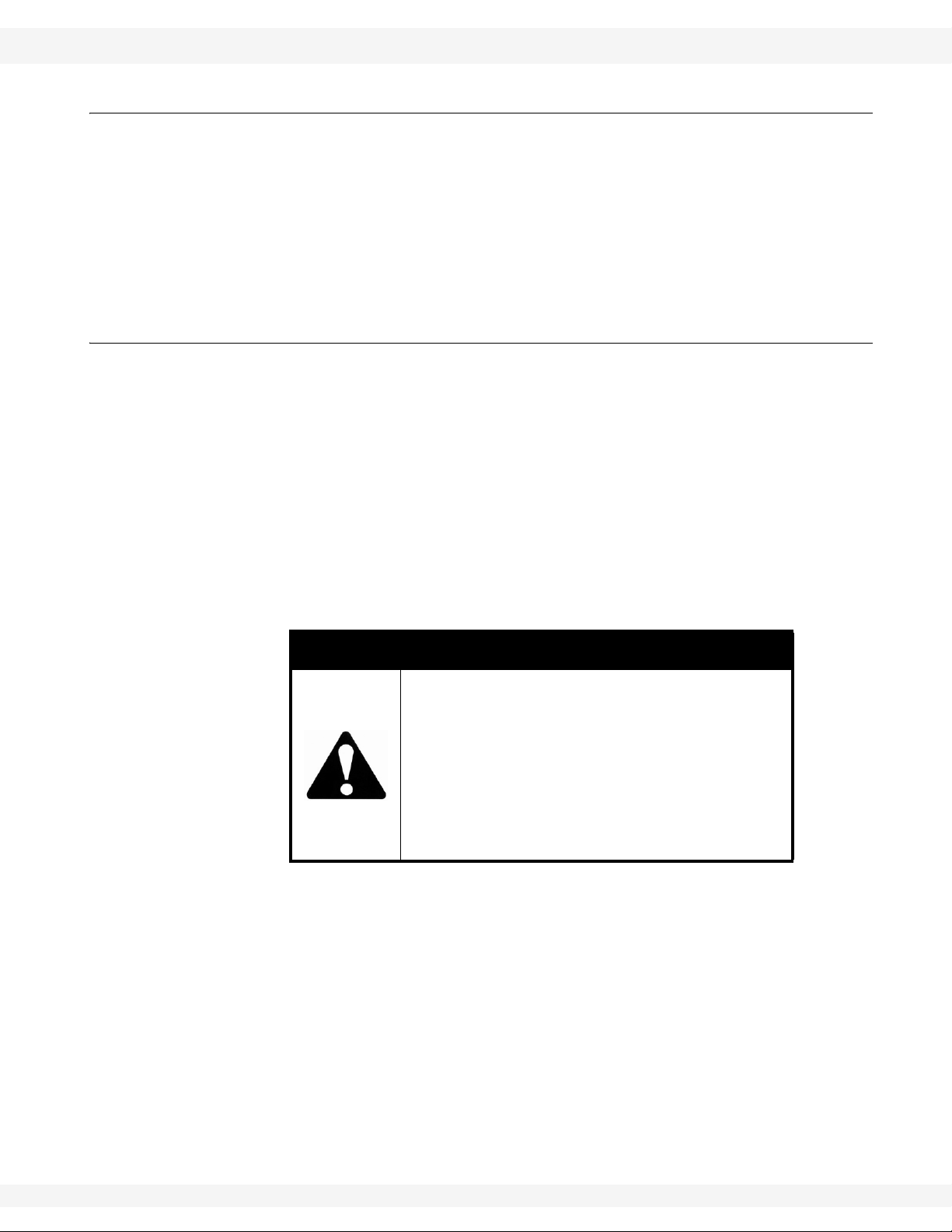
WARNING
Stay away from spike when operating
machine. If a foot is under the machine during
operation, the spike could penetrate it.
IM12 R3 15

3. OPERATION WHEATHEART - SELF-PROPELLED POST POUNDER KIT
MOVE
CYLINDER
LOCK TO
SIDE OF
SPIKE FOR
OPERATION
Figure 3.2
SPIKE
Transport
Position
Operation
Position
LOCKING PIN
LOCKING PIN
HAIRPIN
HAIRPIN
Figure 3.3
WHEEL ARM
MOUNT
WHEEL ARM
MOUNT
3.1. PLACEMENT & OPERATION PROCEDURE TRAILER POST POUNDER MODEL
6. When on a hill/slope, or if the machine moves ahead or back when pounding,
use the spike to secure the pounder in place (Figure 3.4). See Post Pounder
manual for details on operation.
CAUTION
Chock wheels or lower spike to prevent
Note: When building a new fence, it is much easier to operate the machine in reverse
so you can look down the line while pounding the post. This ensures the line is
machine from rolling and to improve stability.
straight.
WARNING
Run-Over Hazard! To prevent injury be
careful when backing up machine.
16 IM12 R3

WHEATHEART - SELF-PROPELLED POST POUNDER KIT 3. OPERATION
SPIKE
RIGHT DRIVE WHEEL
LEFT DRIVE WHEEL
Figure 3.5
CHAIN LOCK
TRAILER POST POUNDER MODEL 3.2. TRANSPORT PREPARATION
3.2. TRANSPORT PREPARATION
Figure 3.4
1. Remove the safety pin under the hitch and lift
the arm up into transport mode (Figure 3.3).
Replace pin.
2. Fully disengage the wheel drive over-centers
(Figure 3.5) and lock into position with the
chain lock.
3. Raise spike and install cylinder lock with
1/4” X 3” locking pin (see Figure 3.6).
4. Adjust valve position by loosening the
appropriate bolt. Swing into transport position
and lock in place.
IM12 R3 17

3. OPERATION WHEATHEART - SELF-PROPELLED POST POUNDER KIT
MOVE CYLINDER
LOCK TO TOP OF
SPIKE PRIOR TO
TRANSPORTING
3.2. TRANSPORT PREPARATION TRAILER POST POUNDER MODEL
NOTICE
To prevent damage to equipment when transporting, lock
spike in position before transporting, and disengage wheel
drive over-centers, making sure they are in the lock
position.
Figure 3.6
18 IM12 R3

WHEATHEART - SELF-PROPELLED POST POUNDER KIT 4. INSTALLATION
Warning: Before continuing, ensure you have read and understand the relevant information
in the safety section. Safety information is provided to help prevent serious injury, death, or
property damage.
TRAILER POST POUNDER MODEL 4.1. RING GEARS
4.Installation
4.1. RING GEARS
1. Jack up and block the frame. Make sure it sits level.
2. Remove the wheels.
3. Deflate tires and break the bead so the tire will not melt during the welding
process.
4. Buff or grind off paint where ring gears will be welded in place.
5. With the wheel rim lying flat, insert ring gear into the inside of each rim. Use a
rubber mallet to ensure the ring gears are square to the inside of each rim
(Figure 4.4).
Important: To ensure ring gears are installed square, place a straight edge on each gear
and measure the distance to the tire rim in 2 places. Then, rotate the straight
edge 90° and measure again. If measurements are the same, then ring gear is
square inside the rim. Use a rubber mallet to level the ring gear if necessary.
6. Tighten the 4 set screws in rotation to lock the ring gear evenly into place on
each rim.
7. With ring gears now in correct position, weld 1” at each set screw (Figure
4.4).
4.2. WHEEL DRIVES
1. Remove the wheel hubs from the spindle (Figure 4.1).
2. Slide an axle cap assembly over each of the two spindles.
Note: Removing the hydraulic motor from the axle cap assembly will make the welding
process easier.
3. Measure 1-1/4” from each of the 4” x 4” spindle backing plates to the inside of
the axle caps (Figure 4.1).
Note: It may be necessary to grind down the gussets on the spindle slightly to obtain
the 1-1/4” measurement.
4. Put a level on the end of each axle cap and tack it in place. Ensure axle caps
are square with frame.
5. Install the rest of the over-center assemblies.
IM12 R3 19

4. INSTALLATION WHEATHEART - SELF-PROPELLED POST POUNDER KIT
1-1/4”
BETWEEN
BACKING
PLATE &
AXLE CAP
CHECK EDGE IS
VERTICAL USING
LEVEL
GUSSETS
AXLE CAP
ASSEMBLY
4.2. WHEEL DRIVES TRAILER POST POUNDER MODEL
Figure 4.1
6. Reinstall the wheel hubs and wheels and engage the over-center handle
(Figure 4.2). Make sure that the pinion gear and ring gear mesh fully,
providing maximum tooth contact. Check also that the pinion clears the ring
gear when the handle is pulled up (disengaged).
Figure 4.2
20 IM12 R3

WHEATHEART - SELF-PROPELLED POST POUNDER KIT 4. INSTALLATION
Figure 4.3
OVER-CENTER
HANDLE (LIFTED)
CHAIN LOCK
Figure 4.4
WELD 1” AT
EACH SET
SCREW
RING GEAR
TRAILER POST POUNDER MODEL 4.2. WHEEL DRIVES
Note: The hydraulic motors have 4
bolts that attach to each motor
mount. The 2 outer bolts must
be checked so they do not rub
against the ring gear. If they do,
the axle cap will need to be
moved back slightly toward the
frame. Ensure motor is oriented
as shown in Figure 4.3.
7. Double-check that pinion
gears and ring gears line up
properly. Remove wheels
and weld axle caps solid to
the spindles.
8. Lift over-center handle.
9. Line up chain locks to hold
each handle and weld in
place (Figure 4.3).
Note: Removing wheels will make it easier to line up chain locks.
10. Weld the axle caps solid to
the frame.
11. Touch up paint and re-install
the over-center assemblies
and the wheels.
IM12 R3 21

4. INSTALLATION WHEATHEART - SELF-PROPELLED POST POUNDER KIT
WHEEL ARM
ASSEMBLY
3/4”X6” BOLT
PIN
1/2” LOCKNUT
1/2” x 4-1/16” x 5-1/2” U-BOLT
TIE DOWN
HANDLE
WHEEL ARM MOUNT
16-1/2”
HAIRPIN
3/4” LOCKNUT
3/8” X 2-3/4”
BOLT
7/16” FLAT
WASHER
3/8” FLAT
WASHER
3/8” FLAT
WASHER
3/8” NUT
RIGHT
SPRING
STEP A
STEP B
STEP C
STEP D
HITCH
LEFT
SPRING
4.3. FRONT WHEEL ASSEMBLY TRAILER POST POUNDER MODEL
4.3. FRONT WHEEL ASSEMBLY
Figure 4.5
22 IM12 R3

WHEATHEART - SELF-PROPELLED POST POUNDER KIT 4. INSTALLATION
1/2” X 5” BOLT
1/2” LOCKNUT
1/2”x1”x5”
U-BOLT
1/2”
LOCKNUT
TRAILER POST POUNDER MODEL 4.4. SPIKE INSTALLATION
1. Install the wheel arm mount over the tie-down handle on the hitch at 16-1/2”
from the front of the hitch. Note that the front 1/2” x 4-1/16” x 5-1/2” u-bolt is
inside the tie-down handle, as shown in STEP A in Figure 4.5. Make sure it is
square to the hitch and tighten with two 1/2” locknuts.
2. Install the right and left springs on the wheel arm mount as shown in STEP B
in Figure 4.5 and connect with hardware shown.
3. Install the wheel arm over the springs as shown in Step C in Figure 4.5 and
secure with a 3/4” x 6” bolt and 3/4” locknut. Make sure the wheel rotates
freely. If it hits the hitch, move the mount forward so the wheel will
clear.
4. Secure the assembly in the working position as shown in STEP D in Figure
4.5 with pin and hairpin.
4.4. SPIKE INSTALLATION
Figure 4.6
1. Remove the bolt from the hitch tube.
2. Place the spike on the hitch tube on the back and line up the holes. Put the
1/2” x 5” bolt through the hole (Figure 4.6).
3. Insert 1/2” x 4” x 5” u-bolt in the front holes and tighten the 1/2” nuts.
IM12 R3 23

4. INSTALLATION WHEATHEART - SELF-PROPELLED POST POUNDER KIT
Figure 4.7
HANDLES
5/16” x 2-1/2” BOLTS
SP VALVE MOUNT ARM
1/2” X 1”
BOLT
SP VALVE MOUNT PLATE
1/2”X1” BOLT
POUNDER VALVE
MOUNT ARM
CONTROL MOUNT HOLDER
4.5. VALVE AND VALVE MOUNT TRAILER POST POUNDER MODEL
4.5. VALVE AND VALVE MOUNT
Refer to Figure 4.8.
1. Loosen the 1/2” x 1” bolt on the
pounder valve mount arm (bolt not
shown) and remove.
2. Slide the SP valve mount arm over
the lower pipe on the pounder valve
mount arm and put it back in the
control mount holder. Set the pounder
control valve back into position and
retighten the bolt.
3. Install the handles into the valve and
attach to the SP valve mount plate
with three 5/16” x 2-1/2” bolts and
locknuts.
4. Move the SP valve mount arm into the
operating position and tighten the
bolts (Figure 4.7).
24 IM12 R3
Figure 4.8

WHEATHEART - SELF-PROPELLED POST POUNDER KIT 4. INSTALLATION
Figure 4.9
SP KIT OIL
RESERVOIR
3/8” NUT
3/8” x 1” BOLT
BRACKET
POST
BIN
1
-
7
/
8
”
TRAILER POST POUNDER MODEL 4.6. OIL RESERVOIR
4.6. OIL RESERVOIR
1. Drain oil and remove existing oil
reservoir (not shown).
2. Insert the SP oil reservoir on the
bracket and bolt it in place with four
3/8” x 1” bolts and 3/8” nuts.
3. Align the bracket and tank assembly so
the tank clears the post bin by approximately 1-7/8” (Figure 4.10).
4. Tack the new bracket on the post bin,
ensure it is even with the bottom and
back end.
5. Make sure the bracket is level and weld
it solid.
IM12 R3 25
Figure 4.10
Note: Tank hydraulic fittings must face toward the motor mount.

4. INSTALLATION WHEATHEART - SELF-PROPELLED POST POUNDER KIT
FITTINGS
MUST FACE
IN THIS
DIRECTION
4.7. HYDRAULICS TRAILER POST POUNDER MODEL
4.7. HYDRAULICS
Note: Hydraulic fittings must face in the direction shown in Figure 4.11.
Figure 4.11
Important: Refer to the Hydraulics Parts for hydraulic hose routing.
26 IM12 R3

WHEATHEART - SELF-PROPELLED POST POUNDER KIT 5. APPENDIX
TRAILER POST POUNDER MODEL 5.1. SP POUNDER PARTS
5.Appendix
5.1. SP POUNDER PARTS
IM12 R3 27

5. APPENDIX WHEATHEART - SELF-PROPELLED POST POUNDER KIT
5.1. SP POUNDER PARTS TRAILER POST POUNDER MODEL
ITEM PART NO. DESCRIPTION QTY
1
2300149COM TRAILER FRAME ON RUBBER,HH,GAS
2
2300183 CASTER WHEEL ASSY,SP POUNDER
3
2300206 WHEEL ARM MOUNT
4
2300207 WHEEL ARM, SP POUNDER
5
9900976 U-BOLT SQ 1/2 NC x 4-1/16 x 5.5 Gr.5 PLT
6
9900945 NUT JAM 1/2 UNC NYLOCK GR5 PLT
7
0200015F RT SP PNDER OC ASSY, COMP. 1SIDE W/MTR/PINION
8
2330208 STEEL HYD TANK
9
0200015F SP PNDER OC ASSY, COMP. 1SIDE W/MTR/PINION
10
2300156 VALVE MNT, SP POUNDER
11
2330100 VALVE MOUNT PLATE-SP POUNDER
12
2330209 STEEL HYD TANK MOUNT
13
9900214 BREATHER CAP, SLIP ON, CHROME
14
1600007 CONTROL LEVER,SD5 VALVE
15
9700083 DCL, VLV CNTRL,SP POUNDER
16
2330214 CHAIN,5/16X2.5X2 LINKS
17
9900201 BOLT, 1/2 X 2-1/4 UNC GR.5 PLD
18
9900697 BOLT HEX 3/8 X 2-3/4 UNC GR5 PLT
19
9900115 BOLT HEX 3/4 X 6 UNC GR5 PLT
20
9900695 NUT NYLOCK 3/4 UNC GR5 PLT
21
9900699 BOLT, 3/8 X 1 UNC GR 5 PLD
22
0601007 NUT NYLOCK 3/8 UNC GR5 PLT
23
9900524 BOLT HEX 5/16 X 2-1/2 UNC GR5 PLT
24
9900520 NUT NYLOCK 5/16 UNC GR5 PLT
25
9900560 BOLT, 1/2 X 2-1/4 UNC GR.5 PLD
26
9900538 NUT NYLOCK 1/2 UNC GR5 PLT
27
9900510 BOLT HEX 3/8 X 2-1/4 UNC GR5 PLT
28
2300152 SP POUNDER SPIKE, INNER SLIDE
29
2300153 SP POUNDER, BOLT ON SPIKE OUTER SLIDE
30
0200308 CYL,2 X 15.625 X 1.125 ROD,1 @ END
31
2330215 CYLINDER GUARD
32
2330216 PIN, LOCKING, 1/4X3
33
2301006 ASSEMBLY, TIRE, 15", COMPLETE
34
2300163 STAND, VALVE BODY
35
P0521001 HOPPER SPRING LEFT
36
P0521002 HOPPER SPRING RIGHT
37
2330213 HITCH PIN, 3/4" X 6-1/2",C/W CLIP
38
2330112 BATTERY/GAS TANK KIT,18HP SP POUND
39
0601008 WASHER FLAT 3/8 PLD
40
9900555 WASHER FLAT 7/16 PLD
41
0200334 RING GEAR W/ SET SCREWS
42
1600041A VALVE,SERIES CIRCUIT,3 SPOOL,NO LEV
1
1
1
1
3
7
1
1
1
1
1
1
1
3
1
2
2
2
1
1
4
7
3
3
1
1
1
1
1
1
1
1
1
1
1
1
1
1
10
2
2
1
28 IM12 R3

WHEATHEART - SELF-PROPELLED POST POUNDER KIT 5. APPENDIX
TRAILER POST POUNDER MODEL 5.1. SP POUNDER PARTS
WHEEL, TANK AND BATTERY PARTS
IM12 R3 29

5. APPENDIX WHEATHEART - SELF-PROPELLED POST POUNDER KIT
5.1. SP POUNDER PARTS TRAILER POST POUNDER MODEL
Wheel Assembly
ITEM PART NO. DESCRIPTION QTY
2 707693 TIRE ASSY,18X9.50-8,6PR,6"HUB 1
3 707691 BOLT W/GREASE GROOVE, VICTORY CAS 1
4 707688 CASTOR HUB SLEEVE, VICTORY 1
5 707689 SPACER, VICTORY CASTOR WHEE L ZERK 1
6 707690 PIPE,1-1/4 SCH40 BK (1.66ODX1.380ID 1
7 2300028 ZERK 5/16 PRESS-IN STYLE(YELOW ZINC 1
8 2330219 CASTER FORK, SP POUNDER 1
9 700499 Caster cap tube 1
11 254001 PIN,QUICK,3/8 X 2-1/2 SQ WIRE 1
12 86754A NUT LOCK JAM 3/4 UNC GR5 PLT 1
17 9900683 WASHER FLAT 1/4 PLT 2
Tank and Battery Assembly
ITEM PART NO. DESCRIPTION QTY
1 4503042 BATTERY TRAY 1
2 2330107 TANK MNT BOTTOM 1
3 2330107B TANK MNT BOTTOM BENT 1
4 2330111 ANGLE, 1.5 X 1.5 X 21.5 1
5 2330106 FUEL TANK TRAY W/ TABS 1
7 1200008 GAS TANK ONLY,W/FITTING,LID & GAUGE 1
8 9900067 Battery, 12 Volt 1
9 1200024 CLAMP HOSE 1/4" 2
10 1200027 FTG,STL,1/4MNPT X 1/4HB 1
11 4500071 UBOLT SQ 1/4NCX8-1/4X9-3/4X4THD PLD 1
13 9900558 BOLT HEX 1/2 X 1 UNC GR5 PLT 4
14 9900538 NUT NYLOCK 1/2 UNC PLT 6
15 9900562 NUT NYLOCK 1/4 UNC PLT 2
16 9900647 BOLT HEX 1/2 X 4 UNC GR5 PLT 2
17 9900683 WASHER FLAT 1/4 PLT 2
NOT SHOWN
9900093 CABLE, BATTERY (12V) 1 ONLY (36") 2
9900261 TARP STRAP, 15"(19" HOOK TO HOOK) 2
H14G HOSE,1/4" GASLINE 24
30 IM12 R3

WHEATHEART - SELF-PROPELLED POST POUNDER KIT 5. APPENDIX
TRAILER POST POUNDER MODEL 5.2. HYDRAULICS PARTS
5.2. HYDRAULICS PARTS
5.2.1. SP POUNDER HYDRAULICS WITH PILOT AUGER
IM12 R3 31

5. APPENDIX WHEATHEART - SELF-PROPELLED POST POUNDER KIT
5.2. HYDRAULICS PARTS TRAILER POST POUNDER MODEL
ITEM PART NO. DESCRIPTION QTY
1 H34X56 HYD HOSE 3/4 X 56 12MPSX10MB 1W 1
1A H34X26 HYD HOSE 3/4 X 26 12MP 1W 1
2 H12X110P2W HYD HOSE 1/2 X 110 8MP-8MP 1W 1
3 H12X52P HYD HOSE 1/2 X 52 8MP-8MP 1W 1
4 H12X42P HYD HOSE 1/2 X 42 8MP-8MP 1W 1
5 H12X58P HYD HOSE 1/2 X 58 8MP-8MP 1W 1
6 H12X60P HYD HOSE 1/2 X 60 8MP-8MP 1W 1
7 H38X96P HYD HOSE 3/8 X 96 6MP-8MP 1W 3
8 H38X78P HYD HOSE 3/8 X 78 6MP-8MP 1W 1
9 H38X104P HYD HOSE 3/8 X 104 6MP-8MP 1W 1
10 H38X100P HYD HOSE 3/8 X 100 6MP-8MP 1W 1
11 H12X32P HOSE,HYD,1/2X32,1/2MNPT X 1/2MNPT,1W 1
12 H34X32P HYD HOSE 3/4 X 32 10MB 1W 1
13 9900054 HYD FIT 8MB-FPX 5
14 9900909 HYD FIT ORIFICE 1/16”, 8MB-FPX 6
15 9900331 HYD FIT ELBOW 8MP-8FPX90 5
16 9900096
ELBOW 10MORB X 1/2FNPSM
a
1
17 0200326 FTG, STL 45, 6MORBX6MKIC 4
18 9900012 FTG,STL,ELB,8MORBX1/2FNPSM 4
19 9900302 FTG,STL,6MORB X 3/8FNPSM 4
20 9900284 FTG,ELB,3/8MNPT X 3/8FNPSM,1/16 ORF 2
21 9900791 FTG,STL,TEE,3/8F/M/FNPT 2
22 9900296 FTG,STL,ELB,10MORBX3/8FNPSM 1
23 9900204 FTG,STL,10MORB X 1/2FNPSM 1
24 9900296 FTG,STL,ELB,10MORBX3/8FNPSM 5
25 H38X21 HOSE,HYD,3/8 X 21",3/8M/MNPT 1
26 H38X28 HOSE,HYD,3/8 X 28",3/8M/MNPT 1
27 H38X144 HOSE,HYD,3/8 X 144",3/8MNPTX6FJIC 4
28 H38X112PP HOSE,HYD,3/8X112,1/2MNPT X 3/8MNPT,1W 2
29 H38X52PP HOSE,HYD,3/8X52,1/2MNPT X 3/8MNPT,1W 2
30 H38X120PP HOSE,HYD,3/8X120,3/8MNPT X 1/2MNPT,1W 2
32 H12X72P HOSE,HYD,1/2X72,1/2MNPT X 1/2MNPT,1W 1
33 H12X32P HOSE,HYD,1/2X32,1/2MNPT X 1/2MNPT,1W 1
34 9900761 FTG,STL,ELB,3/8MNPTX3/8FNPSM 2
35 9900208 FTG,STL,3/4HB X 3/4MNPT 2
36 9900902 6MORBX1/2FNPSM 6
37 9900992 FTG,STL,ELB,3/4MNPT X 3/4FNPSM 1
38 9900215 CLAMP, GEAR #012 (3/4” HOSE) 2
a. Replaces 9900204, HYD FIT 10MB-8FPX in existing hydraulics.
32 IM12 R3

WHEATHEART - SELF-PROPELLED POST POUNDER KIT 5. APPENDIX
TRAILER POST POUNDER MODEL 5.2. HYDRAULICS PARTS
5.2.2. SP POUNDER HYDRAULICS WITHOUT PILOT AUGER
IM12 R3 33


LIMITED WARRANTY
Wheatheart warrants to the buyer that the new machinery is free from defects in material and workmanship.
This warranty is only effective for any new machinery that has not been altered, changed, repaired, or
treated since its delivery to the buyer, other than by Wheatheart or its authorized dealers or employees, and does not apply to accessories, attachments, tools, or parts sold or operated with the new
machinery if they have not been manufactured by Wheatheart.
Wheatheart shall only be liable for defects in the material or workmanship attributed to faulty material
or bad workmanship that can be proved by the buyer, and specifically excludes liability for rep airs arising as a result of normal wear and tear of the new machinery or in any other manner whatsoever, and
without limiting the generality of the foregoing, excludes application or installation of parts not completed in accordance with Wheatheart operation manual, specifications, or printed instructions.
A Warranty Registration Form and Inspection Report must be completed at the time of delivery and
returned to Wheatheart Manufacturing within thirty (30) days.
Warranty Period
Private Farm Use One (1) year from date of purchase.
Commercial, Custom, or Rental Use Ninety (90) days from date of purchase.
Replacement Parts Ninety (90) days from date of replacement
Defective parts are subject to inspection by a Wheatheart representative prior to approval of a warranty claim. All returned parts must be sent to the factory, freight pre-paid, in order to qualify for warranty replacement. Repaired or replaced parts will be returned freight collect.
If these conditions are fulfilled, Wheatheart shall at its own cost and its own option either repair or
replace any defective parts provided that the buyer shall be responsible for all expenses incurred as a
result of repairs, labor , parts, transport ation, or any other work, unless Wheatheart has authorized such
expenses in advance. Normal wear and service items such as belts, hoses, flashing, etc. are excluded
from warranty.
The warranty shall not extend to any repairs, changes, alterations, or replacements made to the new
equipment other than by Wheatheart or its authorized dealers or employees.
This warranty extends only to the original owner of the new equipment.
This warranty is limited to the terms stated herein and is in lieu of any other warranties whether
expressed or implied, and without limiting the generality of the foregoing, excluded all warranties,
expressed or implied, or conditions whether statutory or otherwise as to quality and fitness for any purpose of the new equipment, Wheatheart disclaims all liability for incidental or consequential damages.
This machine is subject to design changes and Wheatheart shall not be required to retro-fit or
exchange items on previously sold units except at its own option.
WARRANTY VOID IF NOT REGISTERED

Wheatheart
Printed in Canada
Part of the Ag Growth International Inc. Group
P.O. Box 151
902 South St. Road 32
Union City, Indiana
Phone: 1-800-354-9502 or 1-765-964-4631
Fax: (765) 964-3529
Toll Free: (877) 934-0649 (Canada & USA)
website: www.wheatheart.com
email: sales@wheatheart.com
© Ag Growth International Inc. 2013
 Loading...