

Read this manual before using product. Failure
Wheatheart
POST POUNDER
S2000 MODEL
ASSEMBLY & OPERATION MANUAL
to follow instructions and safety precautions can
result in serious injury, death, or property
damage. Keep manual for future reference.
Part Number: IM15 R1
Revised: Nov/11

This product has been designed and constructed according to general engineering
standardsa. Other local regulations may apply and must be followed by the operator.
We strongly recommend that all personnel associated with this equipment be trained
in the correct operational and safety procedures required for this product. Periodic
reviews of this manual with all employees should be standard practice. For your
convenience, we include this sign-off sheet so you can record your periodic reviews.
Date Employee Signature Employer Signature
a. Standards include organizations such as the American Society of Agricultural and Biological Engineers,
American National Standards Institute, Canadian Standards Association, International Organization for
Standardization, and/or others.

WHEATHEART - POST POUNDER
S2000 MODEL
TABLE OF CONTENTS
1. Introduction.......................................................................................................................... 5
1.1. Feature Overview and Options................................................................................. 6
1.2. Frame Assembly ...................................................................................................... 7
1.3. Mast Assembly......................................................................................................... 8
1.4. Hugger Arm Assembly ............................................................................................. 9
1.5. PTO Kit................................................................................................................... 10
1.6. Hammer Ballast Kit................................................................................................. 11
2. Safety First.......................................................................................................................... 13
2.1. General Safety ....................................................................................................... 14
2.2. Transport & Placement Safety ............................................................................... 15
2.3. Operation Safety .................................................................................................... 16
2.4. Maintenance Safety................................................................................................ 17
2.5. Hydraulic Safety..................................................................................................... 17
2.6. Safety Decal Locations........................................................................................... 18
2.6.1. Decal Installation/Replacement................................................................ 18
2.6.2. Decal Locations........................................................................................ 18
3. Assembly ............................................................................................................................ 21
3.1. Pre-Assembly......................................................................................................... 21
3.2. Assembling the S2000 Post Pounder..................................................................... 22
3.2.1. Prepare the Frame Assembly................................................................... 22
3.2.2. Connect the Mast Assembly to the Frame Assembly............................... 23
3.2.3. Connect the Hugger Arm and Cylinder to The Mast Assembly................ 25
3.2.4. Install Hammer Ballast.............................................................................. 26
3.3. Installing the PTO Kit.............................................................................................. 28
3.3.1. Installing the PTO Kit Oil Filter Assembly................................................. 29
3.3.2. Installing the PTO Kit Hydraulic Tank....................................................... 30
3.3.3. Installing the PTO Pump Support............................................................. 32
3.3.4. Connecting PTO Kit Hydraulic Hoses....................................................... 33
3.3.5. Filling the Hydraulic Tank......................................................................... 34
4. T ranspor t............................................................................................................................. 35
5. Placement ........................................................................................................................... 37
6. Operation ...................................................................................................................
......... 39
6.1. Pre-Operation Checklist......................................................................................... 39
6.2. Drives..................................................................................................................... 40
6.2.1. Standard Hydraulic Drive.......................................................................... 40
6.2.2. PTO Kit Drive............................................................................................ 41
6.3. Lockouts................................................................................................................. 41
6.4. Start-Up and Break-In ............................................................................................ 41
6.4.1. Startup...................................................................................................... 42
6.4.2. Break-In Period (First 10 Hours)............................................................... 42
IM15 R1 3

WHEATHEART - POST POUNDER
S2000 MODEL
6.5. Operating The S2000 Post Pounder ...................................................................... 43
6.5.1. Loading a Post in the Hugger:.................................................................. 43
6.5.2. Driving a Post: .......................................................................................... 44
6.5.3. Shutdown.................................................................................................. 45
7. Maintenance........................................................................................................................ 47
7.1. Changing the Oil Filter (PTO Kit)............................................................................ 48
7.2. Adding or Replacing Hydraulic Fluid (PTO Kit) ...................................................... 48
7.3. Replacing the Mast Seal......................................................................................... 49
8. Storage................................................................................................................................ 51
9. Troubleshooting ................................................................................................................. 53
10. Appendix........................................................................................................................... 55
10.1. Hydraulic system.................................................................................................. 55
Limited Warranty..................................................................................................................... 57
4 IM15 R1
WHEATHEART - POST POUNDER 1. INTRODUCTION
SERIAL NUMBER: _____________________________
DATE PURCHASED: ___________________________
DEALER: ____________________________________
S2000 MODEL
1.Introduction
Congratulations on your choice of a Wheatheart S2000 Post Pounder to
complement your operation. This equipment has been designed and manufactured to meet the needs of the discriminating buyer for the efficient installation of
fence posts.
Safe, efficient, and trouble-free operation of your post pounder requires that you,
and anyone else who will be involved with operating the unit, read and understand all safety instructions and procedures contained within this manual. A signoff form is provided on the inside front cover for your convenience.
Keep this manual handy for frequent reference and to review with new
personnel. Call your Wheatheart distributor or dealer if you need assistance,
information, or additional copies of the manual.
Operator Orientation: The directions left, right, front, and rear, as mentioned
throughout the manual, are as seen from the tractor driver seat and facing in the
direction of travel when the unit is being transported.
IM15 R1 5

1. INTRODUCTION WHEATHEART - POST POUNDER
1.1. FEATURE OVERVIEW AND OPTIONS S2000 MODEL
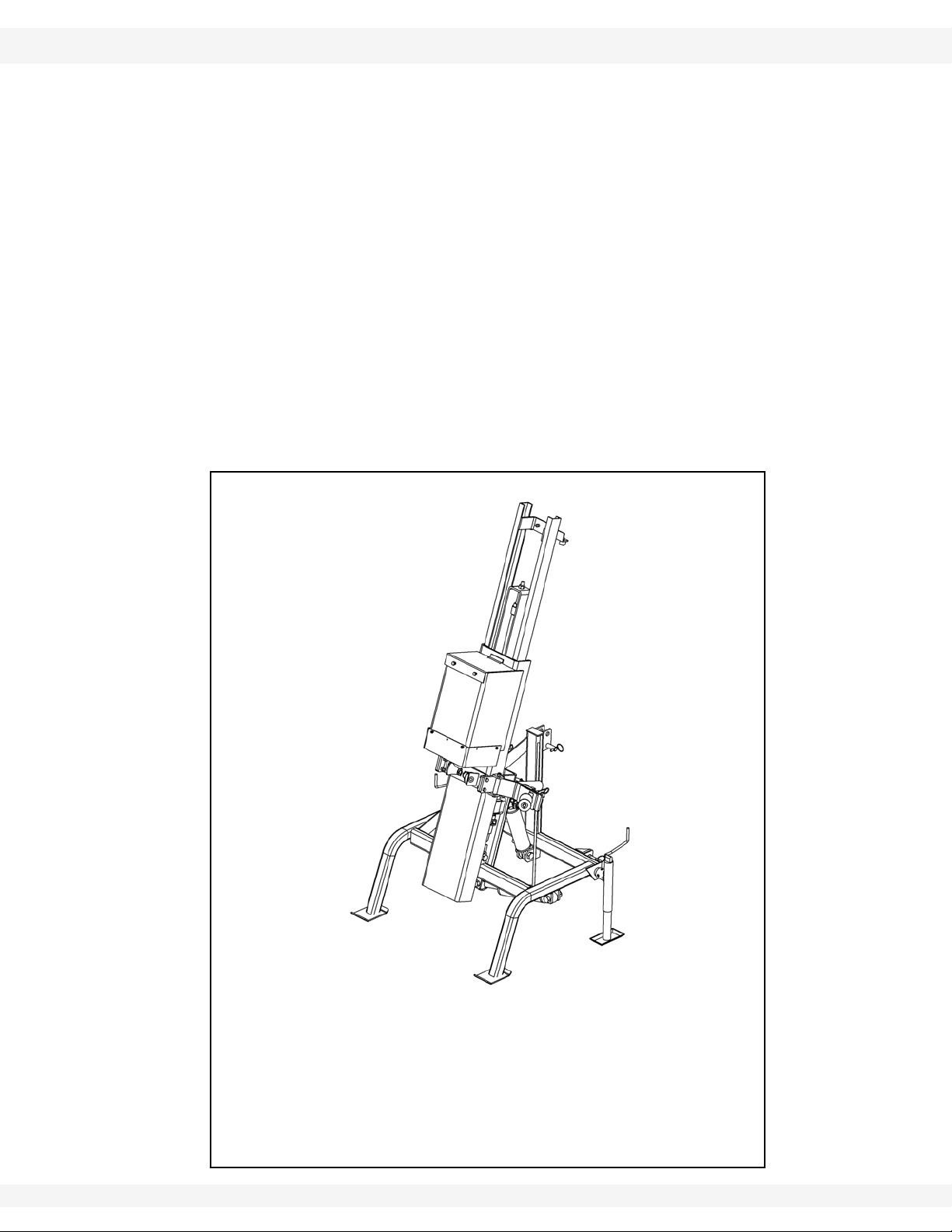
1.1. FEATURE OVERVIEW AND OPTIONS
The S2000 Post Pounder connects to a tractor’s three-point hitch for mobility and
hydraulic power.
The S2000 Post Pounder is delivered packaged in two separate crates. One
crate contains the mast assembly, and the second crate contains the frame
assembly, the hugger assembly, and two support jacks.
Hydraulic power for the standard version of the S2000 Post Pounder is provided
by connecting directly to the tractor’s hydraulic system, including a return line
that is firmly connected to the tractor’s hydraulic fluid reservoir. See “Dri” on
page 40 for detailed information about hydraulic requirements.
The following options are available for the S2000:
• the PTO Kit
• the Hammer Ballast kit
Table 1.1 below lists the S2000 Post Pounder specifications.
Table 1.1 S2000 Post Pounder Specifications
Hammer Weight (without ballast) 320 lbs
Maximum Ballast 280 lbs
Total Weight (without ballast) 720 lbs
Transport Weight (with ballast) 1,000 lbs
Transport Height 8’ 8”
Width 4”1”
Length 3”4”
Hammer Height (Max) 9”4”
Hammer Height (Min) 4’
Hammer Stroke 5’4”
Maximum Post Size (Hugger) 12” diameter
Hydraulic Requirements 7 GPM@1500 PSI
Hammer Tilt Adjustment (front/back) 17º front/back from vertical
Hammer Tilt Adjustment (side-to-side) 16º left/right from vertical
6 IM15 R1
WHEATHEART - POST POUNDER 1. INTRODUCTION
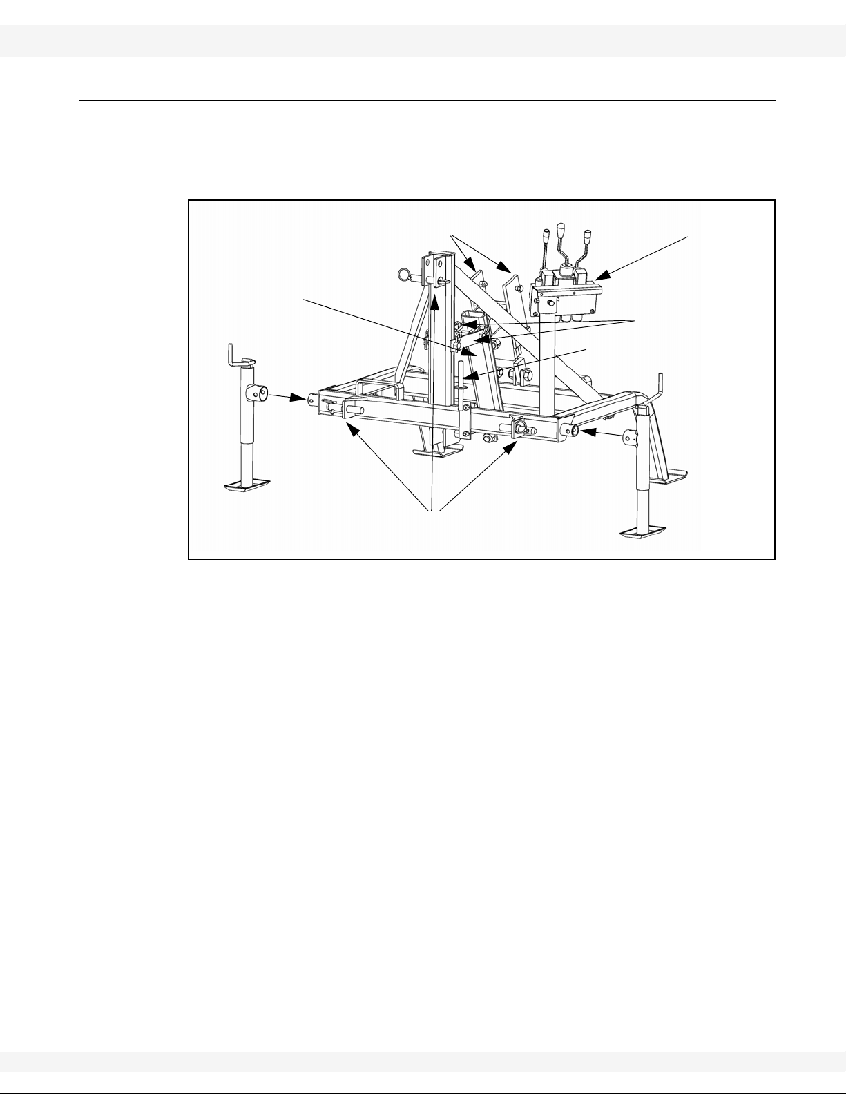
PIVOT ARM
HYDRAULIC CONTROLS
(CLASS II /III THREE-POINT HITCH ATTACHMENTS)
PIVOT ARM
(JACK STAND)
LOCK BARS
PTO PUMP SUPPORT
(OPTIONAL)
(CONTROL VALVE)
MAST ASSEMBLY MOUNT
S2000 MODEL 1.2. FRAME ASSEMBLY
1.2. FRAME ASSEMBLY
The frame assembly is shipped with all hydraulics pre-connected except the
hydraulic hose that must be connected to the mast cylinder. Figure 1.1 shows the
major frame assembly features.
Figure 1.1 Frame Assembly
IM15 R1 7
1. INTRODUCTION WHEATHEART - POST POUNDER
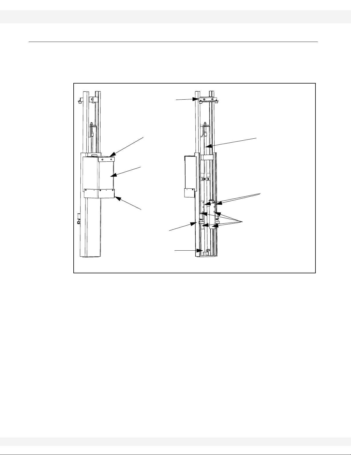
MAST CYLINDER
BALLAST BOX
HAMMER GUARD
MAST CYLINDER
BALLAST BOX COVER
HUGGER BRACKET BOLT HOLES
PIVOT ARM BOLT HOLES
HYDRAULIC CONNECTOR
TOP HAMMER STOP
BOTTOM HAMMER STOP
1.3. MAST ASSEMBLY S2000 MODEL
1.3. MAST ASSEMBLY
The mast assembly mounts on the frame assembly pivot arm, and contains the
mast cylinder, ballast box and hammer, and hammer guard. Figure 1.2 shows the
major features of the assembly.
8 IM15 R1
Figure 1.2 Mast Assembly Detail
WHEATHEART - POST POUNDER 1. INTRODUCTION
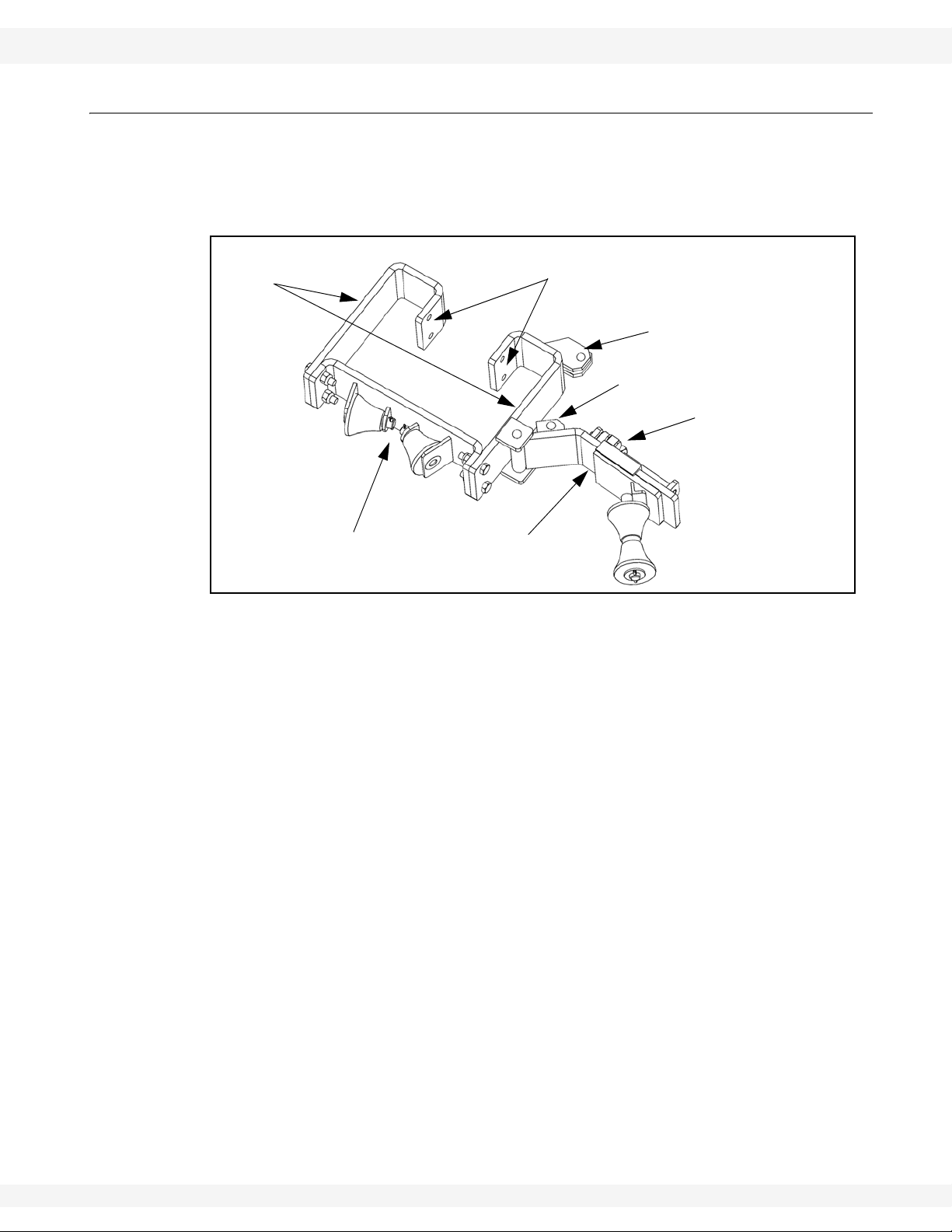
FRONT ROLLER PLATE
HUGGER ARM
MID-CYLINDER BRACKET
CYLINDER ROD-END BRACKET
HUGGER BRACKETS
HUGGER ARM
BOLT HOLES (TO MAST ASSEMBLY)
ADJUSTER BOLT
S2000 MODEL 1.4. HUGGER ARM ASSEMBLY
1.4. HUGGER ARM ASSEMBLY
The hugger arm assembly installs on the mast assembly.The hugger arm opens
and closes hydraulically, and provides posts with support during operation.Figure
1.3 shows the hugger assembly features.
Figure 1.3 Hugger Arm Assembly
IM15 R1 9
1. INTRODUCTION WHEATHEART - POST POUNDER
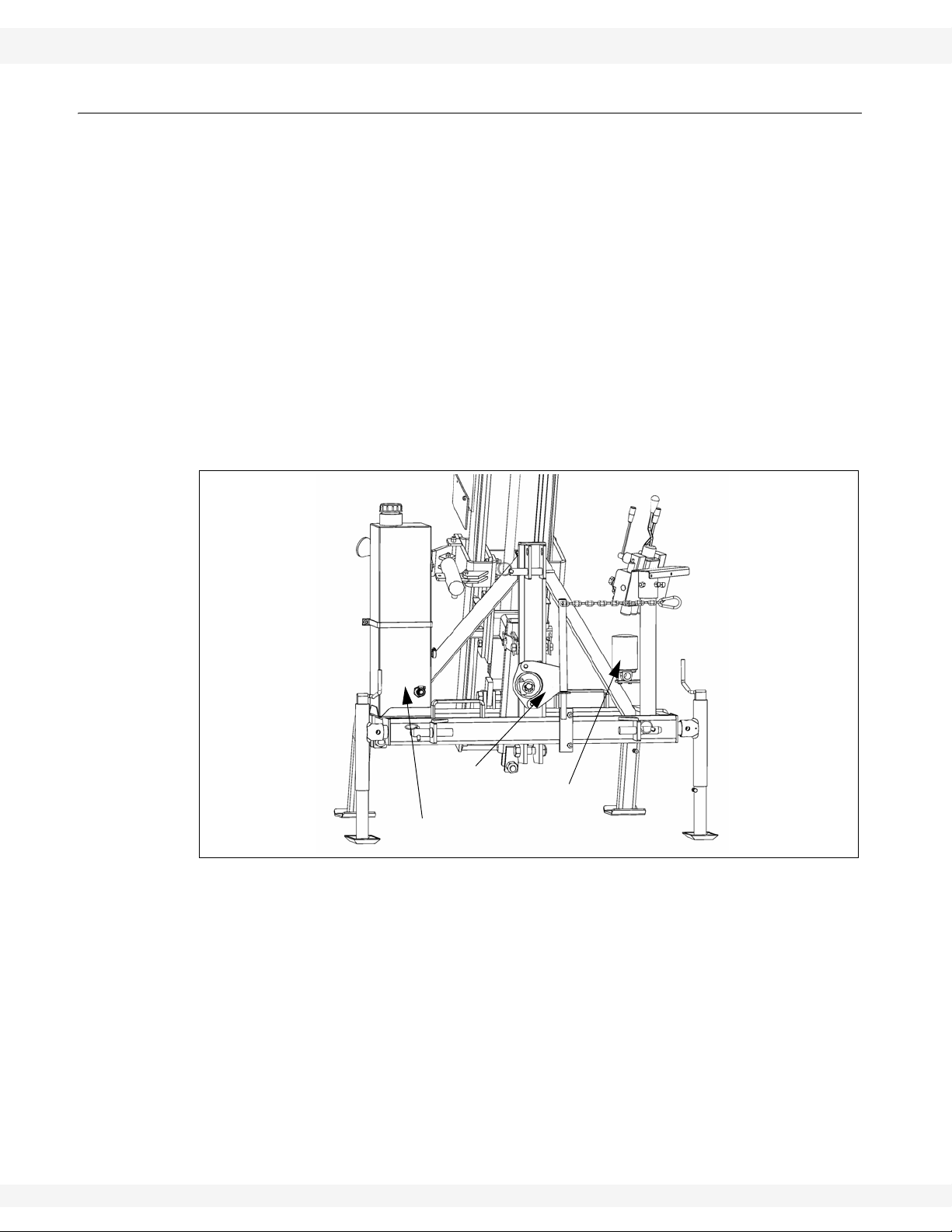
HYDRAULIC TANK
PTO PUMP
OIL FILTER
1.5. PTO KIT S2000 MODEL
1.5. PTO KIT
The optional PTO Kit (Part Number 2311153) provides the S2000 Post Pounder
with a hydraulic system powered by a hydraulic pump that connects to a tractor
PTO shaft.
The kit contains:
• a hydraulic pump and storage post
• a hydraulic tank and support brackets
• a hydraulic oil filter, filter head, and support bracket
• a hydraulic hose
The PTO Kit’s hydraulic pump provides adequate system pressure when
installed and connected to a 540 RPM PTO.
Installation requires modifying an existing hydraulic hose and installing an
additional hose.
Figure 1.4 PTO Kit Major Parts
10 IM15 R1
WHEATHEART - POST POUNDER 1. INTRODUCTION
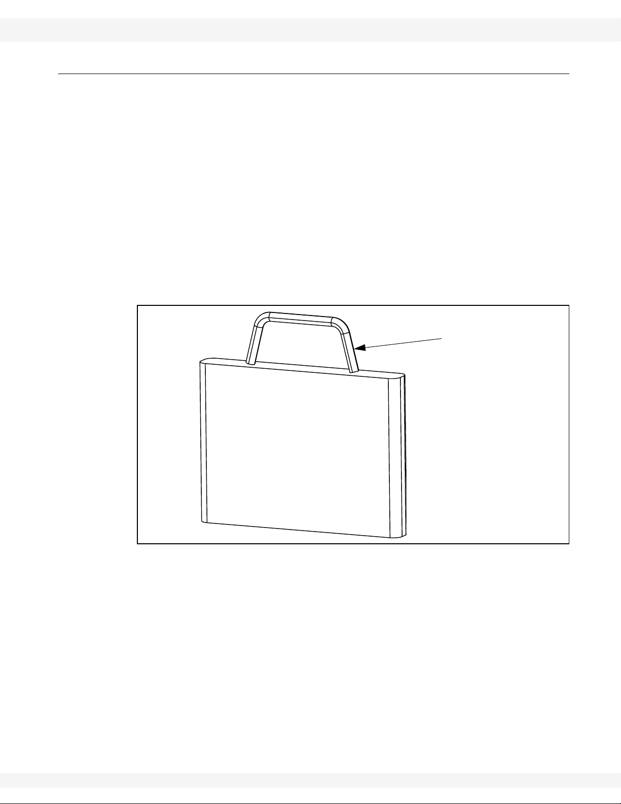
BALLAST WEIGHT BODY
BALLAST WEIGHT
HANDLE
S2000 MODEL 1.6. HAMMER BALLAST KIT
1.6. HAMMER BALLAST KIT
The S2000 Post Pounder is equipped with a ballast box that can be filled with
various ballast weights, up to a maximum of 280 lbs.
The hammer ballast used should be heavy enough to drive the post a reasonable
distance with each hammer drop, but not so heavy that the hammer blows risk
damaging smaller posts.
Wheatheart supplies a Hammer Ballast Kit (Part Number 2311154) that includes
six “suitcase” shaped ballast weights. Figure 1.5 shows a single ballast weight
from the kit.
Each individual ballast weight is 45.4 lbs. Use of all six ballast weights meets the
maximum ballast weight of 280 lbs.
Ballast weights should always be placed in the ballast box with the body first and
the handle up. Failure to do so could damage the ballast weight or the ballast box
during operation of the pounder.
Figure 1.5 Single Ballast Weight from Ballast Kit
IM15 R1 11

1. INTRODUCTION WHEATHEART - POST POUNDER
1.6. HAMMER BALLAST KIT S2000 MODEL
12 IM15 R1
WHEATHEART - POST POUNDER 2. SAFETY FIRST
S2000 MODEL
2.Safety First
The Safety Alert symbol to the left identifies important safety messages on the
product and in the manual. When you see this symbol, be alert to the possibility of personal injury or death. Follow the instructions in the safety messages.
Why is SAFETY important to you?
Three big reasons:
• Accidents disable and kill.
• Accidents cost.
• Accidents can be avoided.
SIGNAL WORDS
Note the use of the signal words DANGER, WARNING, CAUTION, and NOTICE
with the safety messages. The appropriate signal word for each message has
been selected using the definitions below as a guideline.
The Safety Alert symbol means: “ATTENTION, BE ALERT! YOUR SAFETY IS
INVOLVED”.
DANGER
Indicates an imminently hazardous situation
that, if not avoided, will result in serious injury
or death.
WARNING
Indicates a hazardous situation that, if not
avoided, could result in serious injury or
death.
CAUTION
Indicates a hazardous situation that, if not
avoided, may result in minor or moderate
injury.
NOTICE
Indicates a potentially hazardous situation that, if not
avoided, may result in property damage.
IM15 R1 13
2. SAFETY FIRST WHEATHEART - POST POUNDER
2.1. GENERAL SAFETY S2000 MODEL
2.1. GENERAL SAFETY
Important: This general safety section includes instructions that apply to all safety practices.
Any instructions specific to a certain safety practice (e.g., assembly safety), can
be found in the appropriate section. Always read the complete instructional
sections and not just these safety summaries before doing anything with the
equipment.
YOU are responsible for the SAFE use and maintenance of your equipment.
YOU must ensure that you and anyone else who is going to work around the
equipment understands all procedures and related SAFETY information
contained in this manual.
Remember, YOU are the key to safety. Good safety practices not only protect
you, but also the people around you. Make these practices a working part of your
safety program.
• It is the equipment owner and the operator's responsibility to read and understand ALL safety instructions, safety decals, and manuals and follow them
before assembling, operating, or maintaining the equipment. All accidents
can be avoided.
• Equipment owners must give instructions and review the information initially
and annually with all personnel before allowing them to operate this product.
Untrained users/operators expose themselves and bystanders to possible
serious injury or death.
• Use this equipment for its intended purposes only.
• Do not modify the equipment in any way. Unauthorized modification may
impair the function and/or safety, and could affect the life of the equipment.
Any modification to the equipment voids the warranty.
• Do not allow children, spectators, or bystanders within the work area.
• Have a first-aid kit available for use should the need arise, and know how to
use it.
• Provide a fire extinguisher for use in case of an accident. Store in a highly visible and accessible place.
• Wear appropriate protective gear . This list includes, but
is not limited to:
• a hard hat
•gloves
• protective shoes with slip-resistant soles
• protective goggles
• hearing protection
• dust mask or respirator
• For Powered Equipment: before servicing, adjusting, or repairing powered
equipment, unplug, place all controls in neutral or off position, stop the engine
or motor , remove ignition key or lock out power source, and wait for all moving parts to stop.
14 IM15 R1
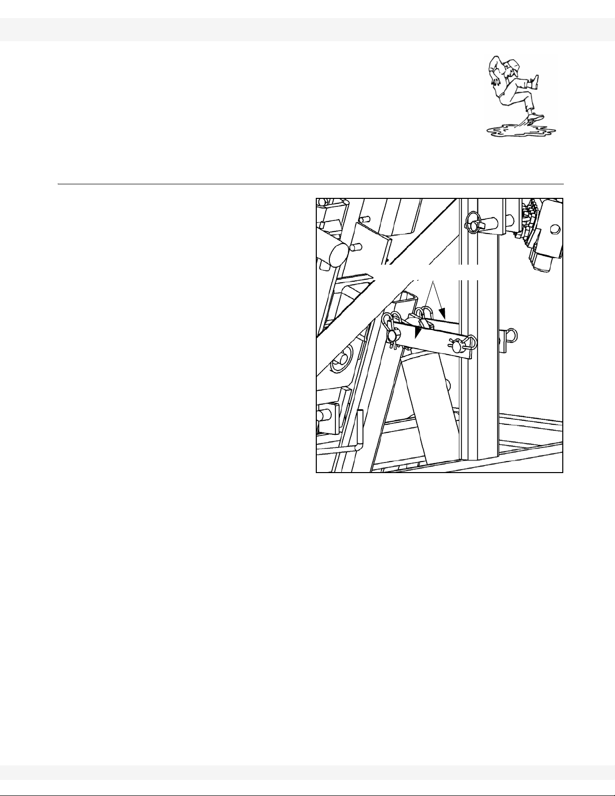
WHEATHEART - POST POUNDER 2. SAFETY FIRST
Figure 2.1 Transport Lock Bars
TRANSPORT LOCK BARS
S2000 MODEL 2.2. TRANSPORT & PLACEMENT SAFETY
• Follow good shop practices:
• keep service area clean and dry
• be sure electrical outlets and tools are properly
grounded
• use adequate light for the job at hand
• Think SAFETY! Work SAFELY!
2.2. TRANSPORT & PLACEMENT SAFETY
• Check with local authorities
regarding transport on public roads. Obey all applicable
laws and regulations.
• Consult tractor operator’s
manual to ensure adequate
towing and lifting capacities.
• Attach pounder to a Category II or III 3-point hitch.
• Ensure transport locks are in
place (see Figure 2.1).
• Ensure that clearances
between pounder and tractor
are maintained during raising, lowering, and positioning.
• Always travel at a safe
speed. Use caution when
turning corners or meeting
traffic.
• Use extreme care and minimum ground speed when operating or transporting on hillsides, over rough
ground, or near ditches or fences.
• Make sure the SMV (slow moving vehicle) emblem and all the lights and
reflectors that are required by local authorities are in place, are clean, and
can be seen by all traffic.
• Do not allow riders on the equipment or towing vehicle during transport.
• Keep away from overhead and buried power lines. Arcing and possible electrocution can occur without direct contact.
• Keep away from buried gas lines. Gas leaks and explosions can occur if gas
lines are ruptured by posts.
• Before transporting, position the ballast box into the fully lowered position.
• Keep jacks raised during transport and normal operation (lower jacks when
storing pounder or operating with hammer at extreme angle).
• Consult local utility companies before operating machine near overhead or
buried power lines / gas lines to confirm line location.
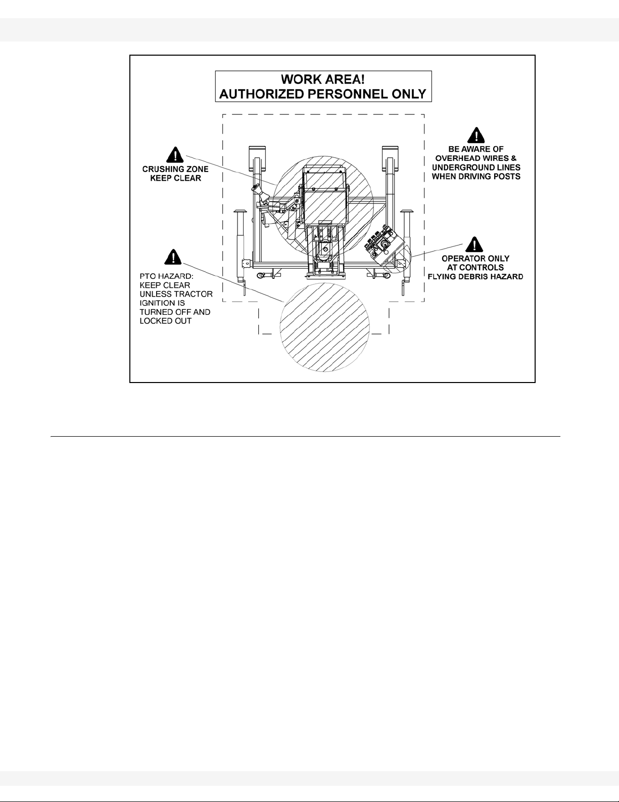
• Review the work safety area diagram (Figure 2.2) before starting work.
IM15 R1 15
2. SAFETY FIRST WHEATHEART - POST POUNDER
2.3. OPERATION SAFETY S2000 MODEL
Figure 2.2 Work Safety Areas
2.3. OPERATION SAFETY
• Have another person nearby and prepared to shut down the equipment in
case of an emergency or accident.
• Do not operate with any of the safety guards removed.
• Keep body, hair, and clothing away from moving parts. Stay away from hammer during operation.
• Do not modify the factory-installed position of the hydraulic control valve
assembly.
• Engage park brake on tractor during operation to prevent movement of the
pounder and tractor.
• Ensure both feet of the pounder frame firmly contact the ground during operation to prevent damage to equipment.
• Do not place more than 280 lbs of weight in ballast box. An overloaded ballast will cause excessive stress on the hydraulic system and can damage the
equipment and/or potentially injure operators.
• Keep jacks raised during transport and normal operation (lower jacks when
storing pounder or operating with hammer at an extreme angle).
16 IM15 R1
WHEATHEART - POST POUNDER 2. SAFETY FIRST
S2000 MODEL 2.4. MAINTENANCE SAFETY
2.4. MAINTENANCE SAFETY
• Before applying pressure to a hydraulic system, make sure all components
are secure, hoses are in good condition, and couplings are tightly connected
and undamaged.
• Relieve pressure from hydraulic circuit before servicing or disconnecting from
tractor.
• Place stands or blocks under the frame before working beneath the machine.
• After maintenance is complete, replace and secure all safety guards and
safety devices, and if applicable, service doors and cleanout covers.
• Remove all tools and unused parts from machine before operation.
• Remove buildup of grease, oil, and debris.
• Inspect all parts. Ensure parts are in good condition and installed properly.
Use only genuine Wheatheart replacement parts or equivalent. Replacement
parts must meet ASAE standards or serious injury may result. Use of
unauthorized parts will void the warranty. If in doubt, contact Wheatheart or your
Wheatheart dealer.
2.5. HYDRAULIC SAFETY
• Always place all hydraulic controls in neutral and relieve system pressure
before disconnecting or working on hydraulic system.
• Keep all components in the hydraulic system tightly secured and in good condition and clean.
• Replace any worn, cut, abraded, flattened, or crimped hoses.
• Do not attempt any makeshift repairs to the hydraulic fittings or hoses with
tape, clamps, or concrete. The hydraulic system operates under extremely
high pressure; such repairs will fail suddenly and create a hazardous and
unsafe condition.
• Before moving a hydraulic cylinder, ensure that the attached component is
safely secured.
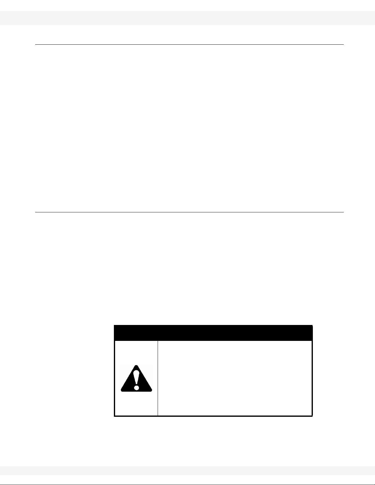
Hydraulic fluid can cause serious injury if it
penetrates the skin. If it does, see a doctor
immediately.
WARNING
• Relieve pressure before disconnecting
hydraulic line.
• Wear proper hand and eye protection and
use wood or cardboard, not hands, when
searching for leaks.
IM15 R1 17

2. SAFETY FIRST WHEATHEART - POST POUNDER
2.6. SAFETY DECAL LOCATIONS S2000 MODEL
2.6. SAFETY DECAL LOCATIONS
• Keep safety decals clean and legible at all times.
• Replace safety decals that are missing or have become illegible. See decal
locations that follow .
• Replaced parts must display the same decal(s) as the original part.
• Safety decals are available from your distributor, dealer, or factory.
2.6.1. DECAL INSTALLATION/REPLACEMENT
1. Decal area must be clean and dry, with a temperature above 50°F (10°C).
Use a solvent to remove all traces of oil from manufacturing before applying
decal.
2. Decide on the exact position before you remove the backing paper.
3. Align the decal over the specified area and carefully press the small portion
with the exposed sticky backing in place.
4. Slowly peel back the remaining paper and carefully smooth the remaining
portion of the decal in place.
5. Small air pockets can be pierced with a pin and smoothed out using the decal
backing paper.
2.6.2. DECAL LOCATIONS
Replicas of the safety decals that are attached to the equipment are shown in the
figure(s) that follow. Proper safety procedures require that you familiarize
yourself with the various safety decals and the areas or particular functions that
the decals apply to as well as the safety precautions that must be taken to avoid
serious injury, death, or equipment damage.
18 IM15 R1

WHEATHEART - POST POUNDER 2. SAFETY FIRST
S2000 MODEL 2.6. SAFETY DECAL LOCATIONS
Figure 2.3 Safety Decal Locations
IM15 R1 19

2. SAFETY FIRST WHEATHEART - POST POUNDER
2.6. SAFETY DECAL LOCATIONS S2000 MODEL
20 IM15 R1

WHEATHEART - POST POUNDER 3. ASSEMBLY
Warning: Before continuing, ensure you have read and understand the relevant information
in the safety section. Safety information is provided to help prevent serious injury, death, or
property damage.
S2000 MODEL 3.1. PRE-ASSEMBLY
3.Assembly
The following procedures and instructions are necessary to ensure proper and
safe assembly of your S2000 Post Pounder.
To assemble the S2000 Post Pounder, perform the following procedures in the
order that they are listed here:
• “Pre-Assembly” on page 21
• “Assembling the S2000 Post Pounder” on page 22
• “Installing the PTO Kit” on page 28 (optional)
3.1. PRE-ASSEMBLY
Upon receiving your shipment:
• Open shipping crates and arrange components on a flat, open workspace.
• Remove bolts on ballast box cover and remove the hardware bag from inside
the ballast box.
• Count components and refer to shipping list to ensure no part is missing.
Contact your dealer or Wheatheart in the event of missing parts.
• Ensure that you have a clear and safe work area, with access to power and
lighting if required.
• Review “General Safety” on page 14.
The following equipment will be needed during assembly:
• a lifting device suitable to support the mast assembly during installation
• safety equipment (e.g. steel toe boots, gloves, goggles)
• vise grips
• mallet
• pry bar
• wrench set (standard/imperial)
• hacksaw or chop saw for cutting hydraulic hose (for PTO Kit only)
IM15 R1 21

3. ASSEMBLY WHEATHEART - POST POUNDER
INSERT LOCK PIN
INSERT LOCK PIN
(TEMPORARY SUPPORT)
(TEMPORARY SUPPORT)
3.2. ASSEMBLING THE S2000 POST POUNDER S2000 MODEL
3.2. ASSEMBLING THE S2000 POST POUNDER
Important: Always have two or more people assembling the equipment. Due to the weight of
the components, do not attempt assembly alone.
Important: Lock bars prevent front-back tilt and limit side-to-side tilt of the pounder mast
during transport and storage. Lock bars should also remain in place during
assembly.
WARNING
Do not attempt assembly without a lifting
device. Components are heavy and present a
crushing hazard which can cause serious
injury or death.
To assemble the S2000 Post Pounder, perform the following procedures in the
order that they are listed:
• “Prepare the Frame Assembly” on page 22
• “Connect the Mast Assembly to the Frame Assembly” on page 23
• “Connect the Hugger Arm and Cylinder to The Mast Assembly” on page 25
• “Install Hammer Ballast” on page 26
3.2.1. PREPARE THE FRAME ASSEMBLY
1. Temporarily support the frame assembly under the frame near the jack stand
locations.
Figure 3.1 Preparing the Frame Assembly
22 IM15 R1

WHEATHEART - POST POUNDER 3. ASSEMBLY
SECURE SLING TO ANGLE IRON HAMMER STOP
BALLAST BOX
S2000 MODEL 3.2. ASSEMBLING THE S2000 POST POUNDER
2. Connect the jack stands to the frame assembly, and secure the jack stands
using the supplied lock pins and hair pins.
3. Remove the temporary supports from the assembly, and adjust the jack
stand legs until the frame assembly is level.
3.2.2. CONNECT THE MAST ASSEMBLY TO THE FRAME ASSEMBLY
1. Position the mast assembly with the ballast box facing upward on a surface
that will protect the back of the assembly from abrasion (e.g. plywood, wood
support blocks, or the bottom of the assembly’s shipping crate).
2. Secure a sling around the centre of the angle iron hammer stop at top of
mast assembly, and attach the sling to a lifting device.
Figure 3.2 Lifting Sling Attachment Point
CAUTION
Secure sling only around the angle iron
hammer stop. Securing at another point could
cause mast to slide when lifted, potentially
damaging equipment or causing injury.
3. Slowly lift the mast assembly into an upright position, then raise or lower it
over the frame assembly until the four mast assembly bolt holes (located on
tabs on the back of the assembly) are as closely aligned with the four bolt
holes on the pivot arm as possible.
4. Connect the mast assembly to the frame assembly using 5/8” x 2” fine-thread
bolts through each bolt hole and secure with 5/8” fine-thread locknuts (see
Figure 3.3). Further alignment of the bolt holes may require very small
adjustments to the height of the mast assembly, or adjustments to the
position of the frame assembly. A pry bar and mallet may be required to
adjust the two assemblies into proper position.
IM15 R1 23

3. ASSEMBLY WHEATHEART - POST POUNDER
MAST CYLINDER
MAST CYLINDER
MAST BOTTOM
HYDRAULIC CONNECTOR
(BACK VIEW)
3.2. ASSEMBLING THE S2000 POST POUNDER S2000 MODEL
Figure 3.3 Connecting Mast Assembly to the Frame Assembly
5. Connect the mast cylinder hydraulic hose to the fitting located at the base of
the mast cylinder.
Figure 3.4 Mast Cylinder Connector Location
24 IM15 R1

WHEATHEART - POST POUNDER 3. ASSEMBLY
FRONT ROLLER PLATE
HUGGER ARM
HUGGER BRACKETS
BOLT HOLES
BOLTS REMOVED
(TO MAST)
MID-CYLINDER BRACKET
FRONT CYLINDER BRACKET
LOCATIONS
HUGGER BOLT
MAST LEVEL
S2000 MODEL 3.2. ASSEMBLING THE S2000 POST POUNDER
3.2.3. CONNECT THE HUGGER ARM AND CYLINDER TO THE MAST ASSEMBLY
1. The hugger assembly comes with the hugger brackets loosely connected to
the front roller plate for ease of shipping. In order to fit the hugger arm around
the mast assembly , first remove the two bolts that secure the front roller plate
to the hugger bracket that is not connected to the hugger arm.
Figure 3.5 Hugger Arm Assembly, Preparation For Installation
Figure 3.6 Hugger Installed on the Mast Assembly
2. Align the four hugger bracket bolt holes with the bolt holes on the mast
assembly.
IM15 R1 25

3. ASSEMBLY WHEATHEART - POST POUNDER
1/2” X 2-1/4 BOLTS
LOCKNUTS
FRONT CYLINDER BRACKET
MID-CYLINDER BRACKET
3.2. ASSEMBLING THE S2000 POST POUNDER S2000 MODEL
3. Secure hugger brackets to the mast assembly with four bolts and locknuts,
but before securing the top-right bolt, place the mast level into place on the
bolt. In order to be roughly accurate, the face of the level should be flush with
the upper edge of the hugger bracket.
4. Secure the front roller plate to the hugger bracket by re-attaching and
tightening the previously removed front roller plate bolts.
5. Ensure that all hugger bracket and front roller plate bolts are tight.
Figure 3.7 Connecting the Hugger Arm Cylinder
6. Position the hugger cylinder so the hydraulic connectors face downward, and
7. Insert the cylinder rod end into the front cylinder bracket (directly on the
3.2.4. INSTALL HAMMER BALLAST
1. Remove the two 1/2”x1-1/2” bolts that secure the ballast box cover to the
2. Fill the ballast box with either:
insert the appropriate mid-cylinder mounting tab into the mid-cylinder
bracket, and fasten with a 1/2” x 2-1/4” bolt and locknut.
hugger arm) and fasten with a 1/2” x 2-1/4” bolt and locknut.
ballast box, and place the bolts and cover aside (see Figure 3.8).
a. pre-weighed ballast of a suitable material (e.g. rebar, slugs, bolts, ball
bearings),
b. or optional “suitcase” ballasts that can be ordered from Wheatheart (Part
Number 2311154). Each ballast weighs 45.4 lbs.
26 IM15 R1

WHEATHEART - POST POUNDER 3. ASSEMBLY
PLACE BALLAST INSIDE
BALLAST BOX COVER
1/2” X 1-1/2” BOLTS
BALLAST BOX
S2000 MODEL 3.2. ASSEMBLING THE S2000 POST POUNDER
WARNING
Do not overfill ballast box. An overloaded
ballast will cause excessive stress on the
hydraulic system and can damage the
equipment and/or potentially injure operators.
Do not exceed 280 lb maximum total ballast
weight.
3. Any extra space in the ballast box can be shimmed with light-weight material
to prevent noise caused by uncontrolled movement of the ballast weights
during operation.
4. Replace the ballast box cover and secure it with the two 1/2” x 1-1/2” bolts
(see Figure 3.8).
Figure 3.8 Installing Hammer Ballast Weights
IM15 R1 27

3. ASSEMBLY WHEATHEART - POST POUNDER
12”
U-BOLT
9”
U-BOLT
3”
U-BOLT
PTO PUMP
SUPPORT POST
OIL FILTER
ASSEMBLY
HYDRAULIC
TANK
3.3. INSTALLING THE PTO KIT S2000 MODEL
3.3. INSTALLING THE PTO KIT
The optional PTO Kit provides the S2000 Post Pounder with a hydraulic system
that is powered by the tractor’s PTO.
To install the PTO Kit, perform the following procedures in the order that they are
listed:
• “Installing the PTO Kit Oil Filter Assembly” on page 29
• “Installing the PTO Kit Hydraulic Tank” on page 30
• “Installing the PTO Pump Support” on page 32
• “Connecting PTO Kit Hydraulic Hoses” on page 33
• “Filling the Hydraulic Tank” on page 34
Figure 3.9 PTO Kit, Part Mounting Locations
28 IM15 R1

WHEATHEART - POST POUNDER 3. ASSEMBLY
OIL FILTER
OIL FILTER HEAD
5/16” X 1” BOLTS
1/2” NYLOCK NUTS
U-BOLT
OIL FILTER BRACKET
S2000 MODEL 3.3. INSTALLING THE PTO KIT
3.3.1. INSTALLING THE PTO KIT OIL FILTER ASSEMBLY
1. Connect the oil filter head to the oil filter bracket using two 5/16” x 1” bolts.
2. Secure the filter bracket and oil filter head to the frame assembly with a
U-bolt and two 1/2” nylock nuts (Figure 3.9 shows the mounting location of
the oil filter assembly).
3. Ensure a good seal between the oil filter and the oil filter head by rubbing a
small amount of clean hydraulic oil on the oil filter’s rubber seal. Install the
oil filter by carefully aligning the threads of each part together, and then
rotating the oil filter clock-wise until a tight seal is achieved.
IM15 R1 29
Figure 3.10 Installing the Oil Filter Assembly

3. ASSEMBLY WHEATHEART - POST POUNDER
1/2” NYLOCK NUTS
HYDRAULIC TANK BRACKET
U-BOLT
3.3. INSTALLING THE PTO KIT S2000 MODEL
3.3.2. INSTALLING THE PTO KIT HYDRAULIC TANK
1. Position the hydraulic tank support bracket on the frame assembly (Figure
3.9 shows the mounting location).
2. Connect the hydraulic tank support bracket to the frame assembly using the
supplied U-bolt (see Figure 3.11).
Figure 3.11 Installing the Hydraulic Tank Support Bracket
3. Place the hydraulic tank in the hydraulic tank support bracket with the lowest
of the two hydraulic connectors facing the three-point hitch, and secure the
tank with the tank strap using the two hex bolts and 5/16 nylock nuts (See
Figure 3.12).
30 IM15 R1

WHEATHEART - POST POUNDER 3. ASSEMBLY
HYDRAULIC TANK
TANK STRAP
2 X 5/16” NYLOCK NUT
2 X 5/16” HEX BOLT
FLUID RETURN
(TO OIL FILTER)
FLUID SUPPLY
(TO PTO PUMP)
S2000 MODEL 3.3. INSTALLING THE PTO KIT
Figure 3.12 Fastening the Hydraulic Tank
IM15 R1 31

3. ASSEMBLY WHEATHEART - POST POUNDER
PTO PUMP
U-BOLT
1/2” NYLOCK NUTS
THREE-POINT HITCH
CENTRE POST
SUPPORT
3.3. INSTALLING THE PTO KIT S2000 MODEL
3.3.3. INSTALLING THE PTO PUMP SUPPORT
1. Facing the three-point hitch, position the PTO pump support on the frame
assembly with the U-bolt centre three inches to the right of the edge of the
hitch centre-post (Figure 3.9 shows the mounting location).
2. Secure the PTO Pump support to the frame assembly using the U-bolt and
two 1/2” nylock nuts.
Figure 3.13 Installing the PTO Pump Support
32 IM15 R1

WHEATHEART - POST POUNDER 3. ASSEMBLY
HYDRAULIC PRESSURE
FLUID RETURN
(H12X72P TO PTO PUMP)
H34X25 TO OIL FILTER
(H34X84 REMOVED)
S2000 MODEL 3.3. INSTALLING THE PTO KIT
3.3.4. CONNECTING PTO KIT HYDRAULIC HOSES
Use the following procedure to connect the hydraulic hoses to the new components included in the PTO Kit. Refer to Figure 10.2 in the Appendix for a det ailed
hydraulic diagram.
1. Connect the hydraulic pressure hose from the control valve to the PTOdriven hydraulic pump’s pressure port.
2. Disconnect the fluid return hose (Part Number H34X84) from the fluid return
connector on the control valve (see Figure 3.14 below).
Figure 3.14 Hose Connections on the Control Valve
3. Divide the return hose into two lengths by measuring, marking, and cutting
4. Clean any debris left over from the end and interior of the two hoses, and
5. Connect the 3/4” NPT connector of the new hydraulic hose supplied with the
the hose 37” from the 1/2” NPT connector.
connect the two lengths as follows:
a. Connect the 1/2” NPT connector on the 37” length of hose to the oil filter
connector closest to the hydraulic tank. Connect the other end of the hose
to the hydraulic tank’s fluid return connector (the highest of the two
connectors), and secure it with the supplied hose clamp.
b. Connect the 3/4” NPT connector on the remaining length of hose to the
fluid intake connector on the hydraulic pump. Connect the other end of the
hose to the hydraulic tank’s supply connector (the lowest of the two
connectors), and secure it with the supplied hose clamp.
kit (H34X25) to the control valve return connector. Connect the remaining
1/2” connector to the other oil filter connector.
IM15 R1 33

3. ASSEMBLY WHEATHEART - POST POUNDER
3.3. INSTALLING THE PTO KIT S2000 MODEL
3.3.5. FILLING THE HYDRAULIC TANK
For general operation, Wheatheart recommends an ISO viscosity 32 heavy duty
industrial hydraulic mineral oil.
After all PTO kit components have been installed correctly, fill the hydraulic tank
with hydraulic oil as follows:
1. Remove the hydraulic tank cap.
2. Add hydraulic oil to the hydraulic tank, but do not overfill (leave space at the
top of the tank).
3. Slowly extend and retract all hydraulic cylinders until air is displaced from the
hydraulic system.
4. Add additional fluid to make up for air displaced from hoses, but do not
overfill the tank.
5. Replace and tighten the tank cap.
34 IM15 R1

WHEATHEART - POST POUNDER 4. TRANSPORT
Warning: Before continuing, ensure you have read and understand the relevant information
in the safety section. Safety information is provided to help prevent serious injury, death, or
property damage.
S2000 MODEL
4.Transport
Follow this procedure when placing the unit into its transport position:
CAUTION
Ensure hitch connection points on tractor and
pounder are level and aligned with each other
before proceeding, to prevent tipping the
pounder and potential injury.
1. Slowly back the tractor up to pounder, leaving at least 6” clearance between
tractor Category II or III 3-point hitch and pounder.
2. Adjust height of 3-point hitch, ensuring that attach points on tractor are not
lower than attach points on pounder.
3. Slowly back tractor up to pounder the remaining distance and attach to
Category II or III 3-point hitch with supplied hitch pins.
4. Once pounder is fully attached to tractor, lift jacks into transport position and
secure with hairpins.
5. Raise the pounder to a safe transport height using the 3-point hitch.
6. Before transporting, ensure hammer/ballast box is positioned in the fully
lowered position, and the mast is fully tipped back and secured by lockbars.
7. Make sure the SMV (Slow Moving Vehicle) emblem and lights and reflectors
that are required by the local authorities are in place, clean, and clearly
visible to all traffic.
8. Consult with local authorities regarding transport on public roads. Obey all
applicable laws and regulations.
Important: Use caution when turning corners or meeting traffic.
WARNING
Do not attempt to move the unit by hand. Only
move when hitched securely to tractor.
WARNING
Use extreme care and use minimum ground
speed when operating or transporting on
hillsides, over rough ground, or near ditches
or fences.
IM15 R1 35

4. TRANSPORT WHEATHEART - POST POUNDER
S2000 MODEL
36 IM15 R1

WHEATHEART - POST POUNDER 5. PLACEMENT
Warning: Before continuing, ensure you have read and understand the relevant information
in the safety section. Safety information is provided to help prevent serious injury, death, or
property damage.
S2000 MODEL
5.Placement
Follow this procedure when placing pounder into its working position:
WARNING
Stay away from overhead or buried power
lines. Arcing and possible electrocution can
occur without direct contact.
WARNING
Consult local utility companies for location of
buried power lines and gas lines before
operating machine.
1. Review the work area safety diagram (Figure 2.2) prior to starting work.
Follow all set-up instructions and do not allow any unauthorized people into
the working area.
2. Be sure there is enough clearance from overhead obstructions, power lines,
or other equipment to move the machine into its working position.
3. Position machine in the desired post area.
4. Lower the 3-point hitch and ensure that both of the post pounder’s support
legs are securely on the ground.
CAUTION
Pounder must have both support legs
securely on the ground before using machine.
5. Set park brake on tractor before dismounting.
WARNING
Use extreme care and minimum ground speed
when operating or transporting on hillsides,
over rough ground, or near ditches or fences.
IM15 R1 37

5. PLACEMENT WHEATHEART - POST POUNDER
S2000 MODEL
38 IM15 R1

WHEATHEART - POST POUNDER 6. OPERATION
Warning: Before continuing, ensure you have read and understand the relevant information
in the safety section. Safety information is provided to help prevent serious injury, death, or
property damage.
S2000 MODEL 6.1. PRE-OPERATION CHECKLIST
6.Operation
NOTICE
Ensure that pounder is attached to equipment that has
sufficient capacity to tow or lift the machine.
CAUTION
Pounder must have both support legs
securely on the ground before using machine.
WARNING
Use extreme care and minimum ground
speed when operating or transporting on
hillsides, over rough ground, or near ditches
or fences.
6.1. PRE-OPERATION CHECKLIST
Efficient and safe operation of this unit requires that each operator reads and
understands the operating procedures and all related safety precautions outlined
in this manual.
Before operating the unit, and each time thereafter, the following should be
reviewed:
• Follow the service schedule.
• Check hydraulic system oil level.
• Ensure that all hydraulic lines are free from damage, and that all fittings
are tight.
• Visually inspect the unit for damage to components. Replace or repair any
damaged or questionable parts.
• Check the work site and clean up the area, if needed.
• Use only a tractor of adequate power and capacity to operate the
machine.
• Check that all guards are installed, secured, and functioning as intended.
Do not operate with missing or damaged guards. Keep guards in good
working order.
IM15 R1 39

6. OPERATION WHEATHEART - POST POUNDER
6.2. DRIVES S2000 MODEL
• Ensure that the pounder is attached to the tractor 3-point hitch with hitch
pins and secured with hairpins.
• Consult local utility companies to identify the location of buried power/gas
lines.
WARNING
Shut off and remove key or lock out power
source before inspecting or servicing the
machine.
DRI
6.2. DRIVES
This unit requires hydraulic power either:
• by direct connection to the tractor’s hydraulic system (standard)
• or by connecting the S2000’s optional integrated hydraulic pump to the tractor’s 540 RPM PTO shaft (PTO Kit installed).
The S2000 Post Pounder is designed to operate with a hydraulic flow rate of
7 GPM@1500 PSI. This provides an acceptable hammer-rise rate of around
three seconds.
If lower flow or pressure are supplied, operation may become slower, sluggish, or
fail entirely.
If flow/pressure is too high, the hammer may rise with too much force and speed,
and there is a risk of damage to the equipment and injury of the operator.
If the hammer lifts too quickly or too slowly, adjust the hydraulic supply from the
tractor, or the PTO speed.
6.2.1. STANDARD HYDRAULIC DRIVE
If you use the tractor’s hydraulic system directly, you must run the post pounder’s
hydraulic fluid return line directly to the tractor’s hydraulic fluid reservoir.
Always fasten the return line in such a way that the end of the hose cannot slip
out of the tractor’s reservoir.
Hydraulic pressure is supplied and regulated by the tractor, apart from an
adjustable pressure relief valve in the post pounder control valve.
40 IM15 R1

WHEATHEART - POST POUNDER 6. OPERATION
S2000 MODEL 6.3. LOCKOUTS
6.2.2. PTO KIT DRIVE
If you use the tractor’s PTO to drive the hydraulic pump supplied in the optional
PTO Kit, ensure that the pump connector is firmly fastened using the connector’s
push-pin shaft lock, and that the arm of the pump assembly is secured to the
tractor (e.g. at the hitch or draw bar using the attached chain.
WARNING
Do not connect or disconnect the PTO pump
while the tractor is on. Always shut off the
tractor, and lock out the ignition before
placing any part of yourself close to the
tractor PTO.
6.3. LOCKOUTS
Before performing any maintenance or servicing, ensure that:
• the tractor is turned off and locked out by removing the ignition key,
• the tractor’s park brake is engaged, and
• the post pounder hammer is in the down position.
Before removing a lockout and supplying power to the post pounder, ensure that:
• all personnel are at a safe distance from the equipment
• the tractor’s parking brake is engaged
• the Pounder’s hydraulic fluid return line is securely fastened, and the end of
the hose cannot slip out of the tractor’s fluid reservoir during operation.
6.4. START-UP AND BREAK-IN
Although there are no operational restrictions on the machine when used for the
first time, it is recommended that some mechanical items should be checked as
a precaution.
Check the hydraulic fluid return line regularly
to ensure that it is directly fastened and
draining into the tractor’s hydraulic fluid
reservoir.
WARNING
IM15 R1 41

6. OPERATION WHEATHEART - POST POUNDER
6.4. START-UP AND BREAK-IN S2000 MODEL
6.4.1. STARTUP
BEFORE STARTING:
• Read power unit operational manual.
• Inspect hydraulic hose fittings for leaks. Tighten if necessary, and replace
worn or damaged hoses.
• Inspect hydraulic mount bolts for tightness.
DURING THE FIRST FEW MINUTES:
• Ensure unit is running properly.
• Some air may be trapped in the hydraulic system; slowly activate hydraulic control valves to ensure all air is out of the system.
• Check hammer raise speed. An ideal hammer-raise time is around three
seconds. If the hammer lifts too quickly or too slowly, adjust the hydraulic
supply from the tractor, or the PTO speed. If the hammer raises with
excessive speed, lower the hydraulic volume/pressure to meet the S2000
hydraulic specifications. If the hammer raises too slowly, increase system
volume/pressure, but do not exceed the system limit of 1500 PSI.
6.4.2. BREAK-IN PERIOD (FIRST 10 HOURS)
AFTER OPERATING FOR FIRST 1/2 HOUR (OR TRANSPORTING):
• Re-torque all fasteners and hardware.
• Check all safety decals are installed and legible. Apply new ones if
needed.
• Check all guards are installed and working as intended.
AFTER OPERATING FOR FIRST 5 AND 10 HOURS:
• Check all hydraulic hoses and fittings for leaks. Tighten fittings where
required, and replace worn or damaged hoses.
• Re-torque all fasteners and hardware.
42 IM15 R1

WHEATHEART - POST POUNDER 6. OPERATION
S2000 MODEL 6.5. OPERATING THE S2000 POST POUNDER
6.5. OPERATING THE S2000 POST POUNDER
Note: Remove and store all lock bars before operating.
WARNING
The Park brake must be engaged on tractor
when pounding posts. If it is not engaged, the
tractor and post pounder could move during
pounder operation and injure the operator.
WARNING
Do not operate the post pounder unless the
hydraulic return line is firmly secured and
draining to the tractor’s fluid reservoir.
6.5.1. LOADING A POST IN THE HUGGER:
1. Using hydraulic controls, raise ballast box and open hugger (Figure 6.1).
Note: See hydraulic valve instructional decal for control details.
WARNING
Keep hands clear of hammer when driving
post. Always use the post hugger to hold the
post in position.
2. Place the post standing up straight against roller plate cones. Ensure that
your hands are clear of hugger. Close the hugger arm to clamp post (Figure
6.1). Some adjustment of the roller arm may be required to hold the post
firmly.
3. To adjust hugger, turn the adjuster bolt on the hugger arm until the roller arm
cones are centered on the post.
4. If various sizes of posts are to be used on a job, the hugger arm may need to
be adjusted to fit at each substantial change of post size.
5. Post is now ready for driving.
IM15 R1 43

6. OPERATION WHEATHEART - POST POUNDER
HUGGER OPEN,
POST PLACED
HUGGER CLOSED,
POST SECURED
6.5. OPERATING THE S2000 POST POUNDER S2000 MODEL
Figure 6.1 Securing a Post with the Hugger
6.5.2. DRIVING A POST:
1. Use hydraulic controls to position mast in the desired position. With the post
held securely in hugger, raise ballast box approximately 1’ to 2’ above the
post before driving the post down. This partial stroke is used to set the post.
WARNING
Do not place more than 280 lbs of weight in
ballast box. An overloaded ballast will cause
excessive stress on the hydraulic system and
can damage the equipment and/or potentially
injure operators.
WARNING
Do not operate the post pounder unless the
hydraulic return line is firmly secured and
draining to the tractor’s fluid reservoir.
44 IM15 R1

WHEATHEART - POST POUNDER 6. OPERATION
S2000 MODEL 6.5. OPERATING THE S2000 POST POUNDER
2. For large posts: raise ballast box as much as needed to safely drive the
post.
For small posts: use shorter strokes because full strokes will damage small
posts.
3. Continue driving the post until the desired post height is achieved.
NOTICE
Do not use the hugger to straighten crooked posts.
Damage to the hugger may result.
NOTICE
Do not raise ballast box at excessive speed. Doing so
could damage the hammer stop or mast frame. Always
reduce the impact at the top hammer stop by slowing the
hammer speed before it reaches the top.
Note: If pounding posts with mast tilted near its maximum (both front-back and side-to-
side tilt), one or both of the jacks may be lowered to provide extra stability.
6.5.3. SHUTDOWN
1. After completing the job, ensure that hammer/ballast box is lowered
completely.
2. Lean mast back into transport position.
3. Shut off flow of oil from the tractor to the post pounder (standard hydraulics),
or turn off the tractor’s PTO.
4. Turn off and lock out the tractor ignition.
5. Reattach lock bars to mast assembly and secure with hairpins.
6. Disconnect hydraulic lines between the Pounder and the tractor (if
applicable), and secure them to the Pounder.
7. Disconnect the hydraulic pump from the tractor’s PTO, and place it on the
PTO storage post (PTO Kit only).
8. Ensure that the jacks stands are secured in storage position (rotated to align
with the frame and secured with a lockpin).
WARNING
DO NOT let ballast box free-fall without
pounding a post.
If the hammer must be lowered without
driving a post, slowly lower the hammer using
the control lever.
IM15 R1 45

6. OPERATION WHEATHEART - POST POUNDER
6.5. OPERATING THE S2000 POST POUNDER S2000 MODEL
46 IM15 R1

WHEATHEART - POST POUNDER 7. MAINTENANCE
Warning: Before continuing, ensure you have read and understand the relevant information
in the safety section. Safety information is provided to help prevent serious injury, death, or
property damage.
S2000 MODEL
7.Maintenance
Before performing any maintenance on this unit:
• shut off and remove key or lock-out the power source,
• ensure ballast box is lowered completely, and mast is secured with lock bars.
Table 7.1 Standard Maintenance Schedule
MAINTENANCE DAILY WEEKLY ANNUALLY
Check cylinder bolts for tightness
Tighten cylinder cap
Check hugger plastic rollers (replace if damaged)
Check mast bolts for tightness
Check top hammer stop bolts for tightness
Check for cracks in frame
Check that all hitch, linch and link pins are secured by hair-
pins where required
Check for main pivot pin tightness
Inspect PTO pump condition
Inspect hydraulic cylinder seals
Inspect hydraulic hoses and connectors
Inspect hydraulic oil (level and condition)
Change oil filter
a
- - --
- - - --
- - - - --
--
Add or change hydraulic oil
a. Annually or more often, according to usage. See “Changing the Oil Filter (PTO Kit)” on page 48.
b. As required. See “Adding or Replacing Hydraulic Fluid (PTO Kit)” on page 48.
b
---
IM15 R1 47

7. MAINTENANCE WHEATHEART - POST POUNDER
7.1. CHANGING THE OIL FILTER (PTO KIT) S2000 MODEL
7.1. CHANGING THE OIL FILTER (PTO KIT)
Change the hydraulic oil filter once a year (minimum), and more often according
to the number of hours of use specified by the oil filter manufacturer.
Wheatheart ships the S2000 Post Pounder equipped with an LHA Products
SPE-15-10, 10-micron filter (rating Beta 10>2). This filter can be replaced by the
same product, or by an oil filter of equivalent performance and physical characteristics.
LHA recommends that you replace the filter after the first 100 hours of operation,
and then after every 250 hours of use. Replacement recommendations for equivalent filters may differ.
NOTICE
Failure to replace the oil filter regularly will contribute to
wear of hydraulic components, and may decrease the
effective life span of the hydraulic fluid.
7.2. ADDING OR REPLACING HYDRAULIC FLUID (PTO KIT)
You will be required to top up the hydraulic tank occasionally to make up for fluid
losses that may occur (e.g. changing the oil filter or other hydraulic components).
When adding hydraulic oil to the hydraulic tank, make sure that the oil you are
adding is compatible with the oil already in the tank.
NOTICE
Topping up the hydraulic tank with an incompatible oil may
decrease the post pounder’s performance, and may
damage hydraulic components.
Drain and replace the hydraulic fluid when it has exceeded its recommended
number of hours of usage. The effective lifespan of a hydraulic oil depends on
the way the post pounder has been maintained and operated, as well as the
specifications of the oil used. Refer to the hydraulic oil manufacturer’s specifications for information about effective oil lifespan.
See “Filling the Hydraulic Tank” on page 34 for hydraulic oil recommendations.
NOTICE
Failure to change the hydraulic fluid after it has exceeded its
recommended life span will lead to increased wear and
damage of hydraulic components.
48 IM15 R1

WHEATHEART - POST POUNDER 7. MAINTENANCE
S2000 MODEL 7.3. REPLACING THE MAST SEAL
7.3. REPLACING THE MAST SEAL
The mast seal kit consists of the following (see Figure 7.1):
• a large O-ring (1)
• a small O-ring (2)
• a buffer (3)
• a polypak (4)
• a dust seal (5)
Figure 7.1 S2000 Mast Seal Kit
Note: Ensure that O-rings are not twisted when placed into the cylinder mast cap.
Twisted O-rings will result in a faulty seal and may cause leaks.
1. Place the large O-ring (1) through the bottom (threaded side) of the mast
cylinder cap (6) into the first groove above the threads.
2. Through the bottom of the mast cylinder cap (6), install the small O-ring (2)
and the buffer (3) into the next recession above the large O-ring (1).
Important: Ensure that the lip on the buffer faces the pressure side (down).
3. Install the polypak (2) into the second groove from the top (wrench side) of
the mast cylinder cap (4). Ensure that the side of the polypak (2) with the oring embedded into it faces the pressure side (down).
4. Insert the dust seal (5) into the top recession with tapered side facing up.
IM15 R1 49

7. MAINTENANCE WHEATHEART - POST POUNDER
7.3. REPLACING THE MAST SEAL S2000 MODEL
50 IM15 R1

WHEATHEART - POST POUNDER 8. STORAGE
Warning: Before continuing, ensure you have read and understand the relevant information
in the safety section. Safety information is provided to help prevent serious injury, death, or
property damage.
S2000 MODEL
8.Storage
To ensure a long, trouble-free life, the following procedure should be followed
when preparing the unit for storage after the season’s use.
• Lock out all power.
• Store the machine on a level surface, free of debris, and in an area away
from human activity. Store in a dry place, or use a tightly secured tarp to
protect the equipment from the weather.
• Ensure that the unit is in transport position.
• Remove all residual material and clean the machine thoroughly.
• Inspect the unit at stress points for cracks.
• Repair or replace any worn or damaged components to prevent any
unnecessary downtime at the start of the next season.
• Touch up paint nicks and scratches to prevent rusting.
• Check hydraulic fittings, hoses, lines, couplers, and valves. Tighten any
loose fittings. Replace any hose that is badly cut, nicked, abraded, or is
separating from the crimped end of the fitting. Secure the hoses to the
machine.
• Inspect and tighten all fasteners; replace fasteners if required.
• Inspect mast cylinder head nut and other hydraulic cylinders for leaks.
Replace seals if necessary.
• Retract all cylinders or grease exposed shafts.
IM15 R1 51

8. STORAGE WHEATHEART - POST POUNDER
S2000 MODEL
52 IM15 R1

WHEATHEART - POST POUNDER 9. TROUBLESHOOTING
S2000 MODEL
9.Troubleshooting
PROBLEM CAUSE SOLUTION
Loose/cracked fittings Tighten/replace fittings
Valve is leaking
Hydraulic cylinder
leaking
Mast cylinder is
leaking
Mast tilts too
slowly
Hammer rises too
quickly
Hammer rises too
slowly
or
Hammer raises
part way, sticks,
and stops
Hammer drops too
slowly
Hammer drops
quickly, but does
not deliver enough
force to drive post
Worn hose Replace hose
Valve spools are worn Replace valve
Worn seal Replace seal
Loose cylinder cap
Head nut is loose Tighten nut
Worn seal Replace seal
Low system flow/pres-
sure
Hydraulic oil level is low Check oil level and add oil if required
Hydraulic line blocked or
kinked
Mechanical binding
Excessive system flow/
pressure
Low system flow/pres-
sure
Oil too hot
Hydraulic line blocked or
kinked
Mechanical binding
Excessive ballast Reduce ballast weight to 280 lbs or less
Mechanical binding
Return line restricted
(blocked, kinked, or otherwise impeded)
Ballast too light Increase ballast weight, but do not exceed 280 lbs.
Hidden obstruction in soil
Soil too hard, post too
large
Tighten cap bolts and monitor leak. If leak persists,
replace cylinder seal
Increase PTO speed or hydraulic flow from tractor
1) Suction blocked hose(s)
2) Replace kinked hose(s)
Check for any obstructions to mast movement,
including hoses, lock bars.
Decrease PTO speed or hydraulic flow from tractor
Increase PTO speed or hydraulic flow from tractor
Tank level low, wrong oil used, oil is contaminated,
or ambient temperature is high for rate of operation.
1) Suction blocked hose
2) Replace kinked hose
Check for any cause of binding or obstruction
between mast parts. Check mast assembly for misalignment, bent mast, broken welds, loose or missing bolts, misaligned components.
Check for any obstructions to mast movement,
including hoses, lock bars.
Suction out blocked lines, and replace kinked hoses
or non-Wheatheart connectors that might obstruct
flow.
Large tree roots or rocks can impede or stop post
from being driven. Reposition post and attempt
again.
It is possible that some combinations of very hard
soils combined with large post diameters will make
pounding a post slow or impossible.
Solution: pre-drill post holes or cut a point on the end
of the post.
IM15 R1 53

9. TROUBLESHOOTING WHEATHEART - POST POUNDER
S2000 MODEL
54 IM15 R1

WHEATHEART - POST POUNDER 10. APPENDIX
S2000 MODEL 10.1. HYDRAULIC SYSTEM
10.Appendix
10.1. HYDRAULIC SYSTEM
Figure 10.1 shows the standard S2000 hydraulic diagram, and Table 10.1
describes the hydraulic connections.
Figure 10.1 S2000 Post Pounder Standard Hydraulic Diagram
Table 10.1 Hydraulic Hose Connections, Standard S2000
REF PART NO. DESCRIPTION LOCATION
1 H34X84 3/4X84,1/2MNPT X 3/4MNPT return, valve to tractor
2 H12X48P2W 1/2X48,1/2MNPT X 1/2MNPT valve to mast cylinder
3 H38X52 3/8X52,1/2MNPT X 1/2MNPT tilt cylinder lower, rod end
4 H38X55 3/8X55,1/2MNPT X 1/2MNPT tilt cylinder lower, cap end
5 H38X40P1 3/8X40,1/2MNPT X 1/2MNPT tilt cylinder top, rod end
6 H38X40P1 3/8X40,1/2MNPT X 1/2MNPT tilt cylinder top, cap end
7 H38X69 3/8X69,3/8MNPT X 1/2MNPT hugger, rod end
8 H38X65 3/8X65,3/8MNPT X 1/2MNPT hugger, cap end
9 H12X72P 1/2X72,1/2MNPT X 1/2MNPT pressure, valve to tractor
IM15 R1 55

10. APPENDIX WHEATHEART - POST POUNDER
10.1. HYDRAULIC SYSTEM S2000 MODEL
Figure 10.2 shows the S2000 PTO Kit Hydraulic diagram, and Table 10.2
describes the hydraulic connections.
Figure 10.2 S2000 Post Pounder Hydraulic Diagram, with PTO Kit Installed
Table 10.2 Hydraulic Hose Connections, PTO Kit
REF PART NO. DESCRIPTION LOCATION
1 H34X25 (new) 3/4X25,1/2MNPT X 3/4MNPT return, valve to filter
2 H12X48P2W 1/2X48,1/2MNPT X 1/2MNPT valve to mast cylinder
3 H38X52 3/8X52,1/2MNPT X 1/2MNPT tilt cylinder lower, rod end
4 H38X55 3/8X55,1/2MNPT X 1/2MNPT tilt cylinder lower, cap end
5 H38X40P1 3/8X40,1/2MNPT X 1/2MNPT tilt cylinder top, rod end
6 H38X40P1 3/8X40,1/2MNPT X 1/2MNPT tilt cylinder top, cap end
7 H38X69 3/8X69,3/8MNPT X 1/2MNPT hugger, rod end
8 H38X65 3/8X65,3/8MNPT X 1/2MNPT hugger, piston end
9 H12X72P 1/2X72,1/2MNPT X 1/2MNPT pressure, valve to PTO pump
10 H34X84* (partial) 3/4X37,1/2MNPT return, to tank from filter
11 H34X84** (partial) 3/4X47,3/4MNPT supply, from tank to PTO pump
* First part of hose H34X84, cut 37 inches from the 1/2” NPT connector
**Second part of hose H34X84, approximately 47” in length.
56 IM15 R1

LIMITED WARRANTY
Wheatheart warrants to the buyer that the new machinery is free from defects in material and
workmanship.
This warranty is only effective for any new machinery that has not been altered, changed,
repaired, or treated since its delivery to the buyer, other than by Wheatheart or its authorized
dealers or employees, and does not apply to accessories, attachments, tools, or parts sold or
operated with the new machinery if they have not been manufactured by Wheatheart.
Wheatheart shall only be liable for defects in the material or workmanship attributed to faulty
material or bad workmanship that can be proved by the buyer, and specifically excludes liability
for repairs arising as a result of normal wear and tear of the new machinery or in any other manner whatsoever, and without limiting the generality of the foregoing, excludes application or
installation of parts not completed in accordance with Wheatheart operation manual, specifications, or printed instructions.
A Warranty Registration Form and Inspection Report must be completed at the time of delivery
and returned to Wheatheart Manufacturing within thirty (30) days.
Warranty Period
Private Farm Use One (1) year from date of purchase.
Commercial, Custom, or Rental Use Ninety (90) days from date of purchase.
Replacement Parts Ninety (90) days from date of replacement
Defective parts are subject to inspection by a Wheatheart representative prior to approval of a
warranty claim. All returned parts must be sent to the factory, freight pre-paid, in order to qualify
for warranty replacement. Repaired or replaced parts will be returned freight collect.
If these conditions are fulfilled, Wheatheart shall at its own cost and its own option either repair
or replace any defective parts provided that the buyer shall be responsible for all expenses
incurred as a result of repairs, labor , part s, transporta tion, or any other work, unless Wheatheart
has authorized such expenses in advance. Normal wear and service items such as belts,
hoses, flashing, etc. are excluded from warranty.
The warranty shall not extend to any repairs, changes, alterations, or replacements made to the
new equipment other than by Wheatheart or its authorized dealers or employees.
This warranty extends only to the original owner of the new equipment.
This warranty is limited to the terms stated herein and is in lieu of any other warranties whether
expressed or implied, and without limiting the generality of the foregoing, excluded all warranties, expressed or implied, or conditions whether statutory or otherwise as to quality and fitness
for any purpose of the new equipment, Wheatheart disclaims all liability for incidental or consequential damages.
This machine is subject to design changes and Wheatheart shall not be required to retro-fit or
exchange items on previously sold units except at its own option.
WARRANTY VOID IF NOT REGISTERED

Wheatheart
Printed in Canada
Part of the Ag Growth International Inc. Group
P.O. Box 151
902 South St. Road 32
Union City, Indiana
Phone: 1-800-354-9502 or 1-765-964-4631
Fax: (765) 964-3529
Toll Free: (877) 934-0649 (Canada & USA)
website: www.wheatheart.com
email: sales@wheatheart.com
© Ag Growth International Inc. 2013
 Loading...