

Read this manual before using product. Failure
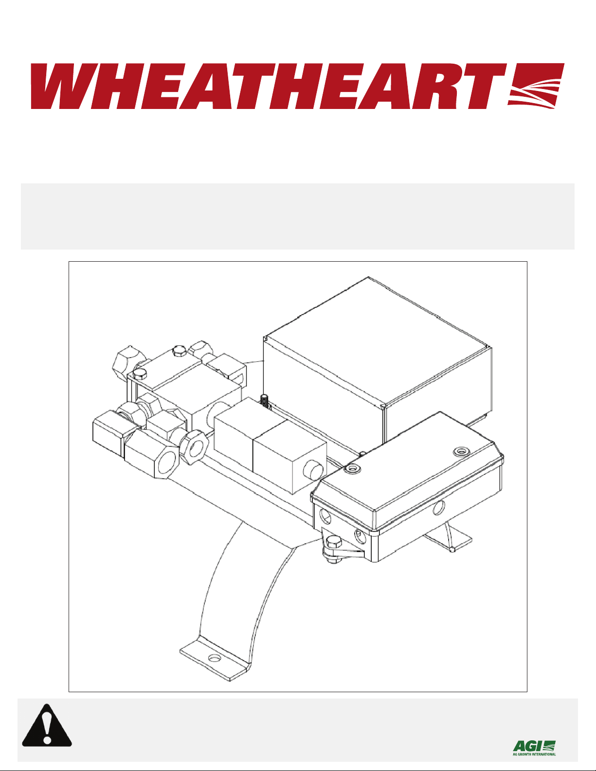
REMOTE POWERSWING
A232, A233, A234, A235, AND A236 MODELS
ASSEMBLY AND OPERATION MANUAL
to follow instructions and safety precautions can
result in serious injury, death, or property
damage. Keep manual for future reference.
Part Number: 30664 R0
Revised: 22/3/12

This product has been designed and constructed according to general engineering
standardsa. Other local regulations may apply and must be followed by the operator.
We strongly recommend that all personnel associated with this equipment be trained
in the correct operational and safety procedures required for this product. Periodic
reviews of this manual with all employees should be standard practice. For your
convenience, we include this sign-off sheet so you can record your periodic reviews.
Date Employee Signature Employer Signature
a. Standards include organizations such as the American Society of Agricultural and Biological Engineers,
American National Standards Institute, Canadian Standards Association, International Organization for
Standardization, and/or others.

WHEATHEART - REMOTE POWERSWING
A232, A233, A234, A235, AND A236 MODELS
TABLE OF CONTENTS
1. Safety First............................................................................................................................ 5
1.1. General Safety ......................................................................................................... 6
2. Assembly .............................................................................................................................. 9
2.1. Remote Mount Installation........................................................................................ 9
2.2. Hydraulic Configuration .......................................................................................... 10
2.3. Antenna Preparation .............................................................................................. 11
3. Operation ............................................................................................................................ 13
4. Maintenance ....................................................................................................................... 15
5. Troubleshooting ................................................................................................................. 17
6. Appendix............................................................................................................................. 19
6.1. Remote Coding ...................................................................................................... 19
Limited Warranty ..................................................................................................................... 21
30664 R0 3

WHEATHEART - REMOTE POWERSWING
A232, A233, A234, A235, AND A236 MODELS
4 30664 R0
WHEATHEART - REMOTE POWERSWING 1. SAFETY FIRST
A232, A233, A234, A235, AND A236 MODELS
1. Safety First
The Safety Alert symbol to the left identifies important safety messages on the
product and in the manual. When you see this symbol, be alert to the possibility of personal injury or death. Follow the instructions in the safety messages.
Why is SAFETY important to you?
Three big reasons:
• Accidents disable and kill.
• Accidents cost.
• Accidents can be avoided.
SIGNAL WORDS
Note the use of the signal words DANGER, WARNING, CAUTION, and NOTICE
with the safety messages. The appropriate signal word for each message has
been selected using the definitions below as a guideline.
The Safety Alert symbol means ATTENTION, BE ALERT!, YOUR SAFETY IS
INVOLVED.
DANGER
Indicates an imminently hazardous situation
that, if not avoided, will result in serious injury
or death.
WARNING
Indicates a hazardous situation that, if not
avoided, could result in serious injury or
death.
CAUTION
Indicates a hazardous situation that, if not
avoided, may result in minor or moderate
injury.
NOTICE
Indicates a potentially hazardous situation that, if not
avoided, may result in property damage.
30664 R0 5
1. SAFETY FIRST WHEATHEART - REMOTE POWERSWING
1.1. GENERAL SAFETY A232, A233, A234, A235, AND A236 MODELS
1.1. GENERAL SAFETY
Important: The general safety section includes instructions that apply to all safety practices.
Any instructions specific to a certain safety practice (e.g., assembly safety), can
be found in the appropriate section. Always read the complete instructional
sections and not just these safety summaries before doing anything with the
equipment.
YOU are responsible for the SAFE use and maintenance of your equipment.
YOU must ensure that you and anyone else who is going to work around the
equipment understands all procedures and related SAFETY information
contained in this manual.
Remember, YOU are the key to safety. Good safety practices not only protect
you, but also the people around you. Make these practices a working part of your
safety program.
• It is the equipment owner and the operator's responsibility to read and understand ALL safety instructions, safety decals, and manuals and follow them
before assembling operating, or maintaining the equipment. All accidents can
be avoided.
• Equipment owners must give instructions and review the information initially
and anually with all personnel before allowing them to operate this product.
Untrained users/operators expose themselves and bystanders to possible
serious injury or death.
• Use this equipment for its intended purposes only.
• Do not modify the equipment in any way. Unauthorized modification may
impair the function and/or safety, and could affect the life of the equipment.
Any modification to the equipment voids the warranty.
• Do not allow children, spectators, or bystanders within the work area.
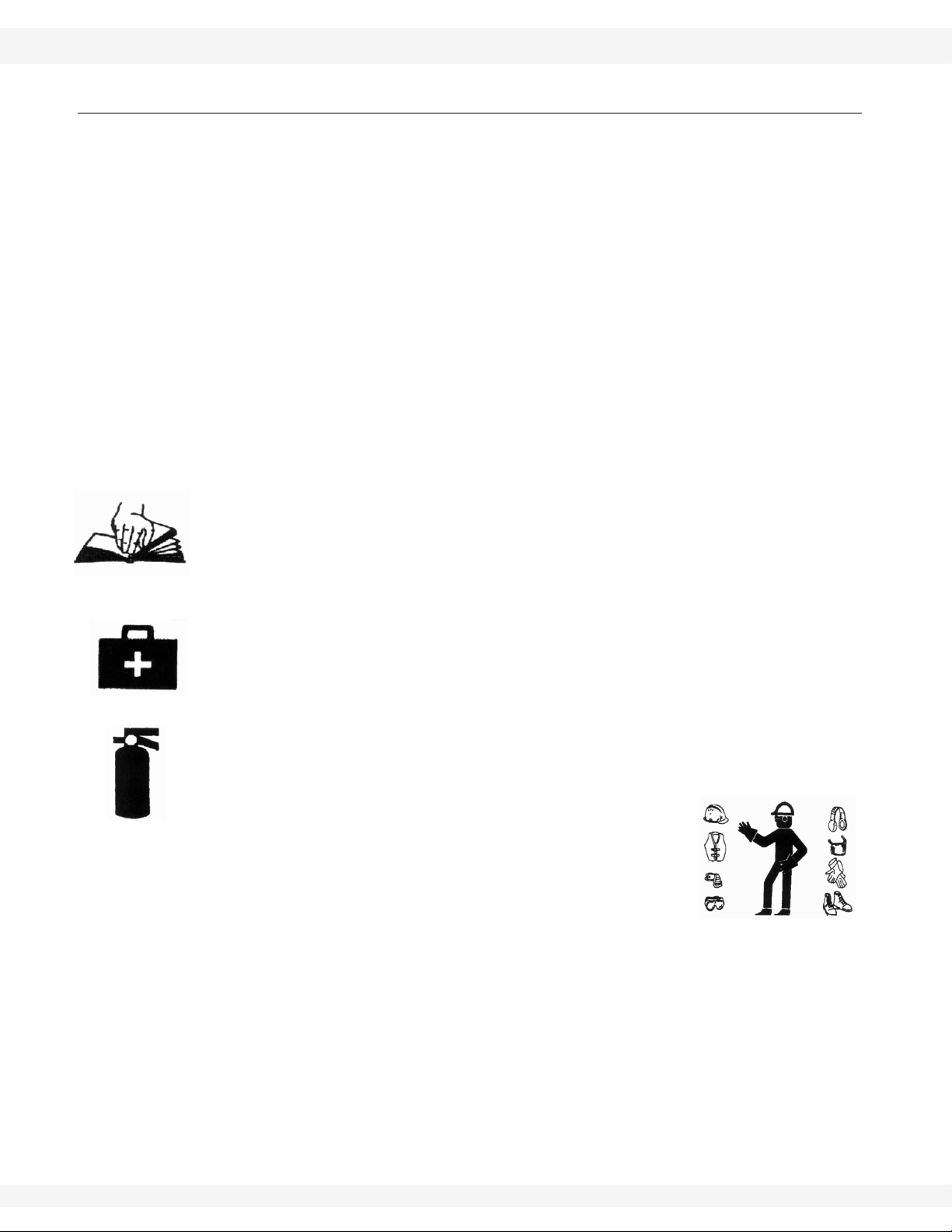
• Have a first-aid kit available for use should the need arise, and know how to
use it.
• Provide a fire extinguisher for use in case of an accident. Store in a highly visible place.
• Wear appropriate protective gear. This list includes, but
is not limited to:
• a hard hat
•gloves
• protective shoes with slip-resistant soles
• protective goggles
• hearing protection
• For Powered Equipment: before servicing, adjusting, or repairing powered
equipment, unplug, place all controls in neutral or off position, stop the engine
or motor, remove ignition key or lock out power source, and wait for all moving parts to stop.
6 30664 R0

WHEATHEART - REMOTE POWERSWING 1. SAFETY FIRST
A232, A233, A234, A235, AND A236 MODELS 1.1. GENERAL SAFETY
• Follow good shop practices:
• keep service area clean and dry
• be sure electrical outlets and tools are properly
grounded
• use adequate light for the job at hand
• Think SAFETY! Work SAFELY!
30664 R0 7

1. SAFETY FIRST WHEATHEART - REMOTE POWERSWING
1.1. GENERAL SAFETY A232, A233, A234, A235, AND A236 MODELS
8 30664 R0

WHEATHEART - REMOTE POWERSWING 2. ASSEMBLY
Figure 2.1
A232, A233, A234, A235, AND A236 MODELS 2.1. REMOTE MOUNT INSTALLATION
2. Assembly
The manual for the Hydraulic Powerswing is included with this kit and installing
the Remote Powerswing will follow all the same steps with a few additional steps
that must be completed first. Be sure to read this insert over PRIOR to assembly
to insure correct assembly order.
Note: If not using the 7-pin electrical connector supplied with the Powerswing, be sure
to note that the white wire of this cable is to be connected to a ground and the
black wire is to be connected to a 12- to 15-V source. It is strongly recommended
you get a qualified professional to ensure proper wiring.
NOTICE
Failure to connect the wires in polarity described will result
in unsafe operation and can cause undesirable effects such
as failure of the remote to function.
2.1. REMOTE MOUNT INSTALLATION
The Remote Powerswing Retrofit is designed to allow the Hydraulic Powerswing
to function via remote. To install, follow the steps below and refer to Figure 2.1
and Figure 2.3.
1. Retrofit Only: Disconnect the hydraulic hoses from the old hydraulic valve.
2. Retrofit Only: Unbolt the old valve from the mount.
3. Place one of the
supplied spacers on
each of the three
bolts on the lower
side of the Remote
Retrofit mount (see
Figure 2.1).
4. Re-attach to the
original valve mount.
5. Connect the hydraulic
hoses to the new
valve.
30664 R0 9

2. ASSEMBLY WHEATHEART - REMOTE POWERSWING
Figure 2.2
2.2. HYDRAULIC CONFIGURATION A232, A233, A234, A235, AND A236 MODELS
2.2. HYDRAULIC CONFIGURATION
This valve is designed to be used with
tractors / hydraulic pumps that operate
in open loop format or with CLLS
(Closed Loop Load Sensing) with simple modifications. If you are unsure of
your hydraulic configuration it is recommended you contact your tractor dealer
to inquire. If you are unable to determine hydraulic pump configuration, we
recommend installing the valve in the
Open Loop configuration.
When shipped, the valve will be set-up
for Open Loop usage. Should you
require the valve set-up for CLLS,
follow these steps and refer to Figure
2.3.
1. Use two 7/16" wrenches to loosen
the two 1/4" bolts holding the valve
on.
2. Lift the valve, bolts, and spacers
from the mount as one, rotate it
180° as shown in Figure 2.3.
3. Insert the bolts into the second set of holes and retighten.
10 30664 R0
Figure 2.3
Note: There are 2 sets of holes into which to bolt the valve. When shipped, the valve
will be bolted through the holes closest to the end of the mount. When switching
to CLLS, you must use the other set of holes that are closer to the center of the
mount.
Note: When rotating the valve, the wires may become too short. If this occurs open the
junction box lid and slide extra wire out.

WHEATHEART - REMOTE POWERSWING 2. ASSEMBLY
A232, A233, A234, A235, AND A236 MODELS 2.3. ANTENNA PREPARATION
2.3. ANTENNA PREPARATION
When shipped, the antenna for the Remote Powerswing receiver will be within its
protective steel housing. The antenna must be positioned outside of the housing
(Figure 2.2) in order to get proper reception. Follow the steps below to adjust.
1. Use two 7/16" wrenches to unbolt the two 1/4" bolts holding the protective
receiver box onto the mount plate (see Figure 2.2).
2. Slide the receiver box off of the housing.
3. Use a hex head wrench and screwdriver to remove the four #10 x 3/4” bolts
securing the receiver to the housing bottom plate.
4. Turn the antenna downward and feed it through the appropriate hole in the
housing bottom plate.
Note: Section 6. Appendix on page 19 can be completed conveniently here.
5. Re-fasten the receiver to the bottom plate making sure to use the spacer
plates as they were installed before.
6. Slide the receiver box back on and bolt the assembly back to the mount.
Figure 2.4 Remote Powerswing Complete Assembly
30664 R0 11

2. ASSEMBLY WHEATHEART - REMOTE POWERSWING
2.3. ANTENNA PREPARATION A232, A233, A234, A235, AND A236 MODELS
Table 2.1
ITEM PART NO. DESCRIPTION ITEM PART NO. DESCRIPTION
1 16422 Remote Powerswing Mount 10” 11 28725 Bolt, 1/4” x 2” GR5 PLTD
2 16420 Receiver Box Cover 12 19538 Bolt, 5/16” x 3/4” GR2 PLTD
3 51354 Receiver Housing Bottom Plate 13 19594 Flange Nut, 1/4” PLTD
4 28650 Remote Receiver Box 14 19980 Nut, Nylock 5/16” PLTD
5 51357 Spacer Plate 15 28656 Bolt, #10 x 3/4” GR2 PLTD
6 51351 Electro-Hydraulic Valve Spacer 16 28657 Nut, Nylock #10 PLTD
7 51352 Electro-Hydraulic Valve Retainer 17 28315 Orifice - Drilled 3/8” Pipe Plug
8 28651 Electro-Hydraulic 4-Way Valve 18 28477 #8 ORB - 1/2” FNPT Adapter
9 28652 Junction Box 19 28654 #8 ORB - 1/2” FNPT 90° Adapter
10 19988 Bolt, 1/4” x 1” GR2 PLTD 20 12360 1/2” Brass Elbow
12 30664 R0

WHEATHEART - REMOTE POWERSWING 3. OPERATION
A232, A233, A234, A235, AND A236 MODELS
3. Operation
The hand held transmitter has 8 buttons on it but only 2 are needed. To operate
the swing, press the green "on" button in rows 1 and 2. These will be the only
buttons that will move the swing.
Note: If desired, the direction of movement when pressing each button can be reversed
by reversing the connection of the two hoses to the tractor. To change the
direction of movement using the manual switch located in the junction box, rotate
the switch in the box.
It is important to locate the remote such that the buttons cannot be pressed
accidentally. Carry and handle the remote in a way to avoid accidental
depression at all times.
WARNING
If the swing is operated accidentally, serious injury to
unsuspecting bystanders and/or damage to the auger can
occur.
30664 R0 13

3. OPERATION WHEATHEART - REMOTE POWERSWING
A232, A233, A234, A235, AND A236 MODELS
14 30664 R0

WHEATHEART - REMOTE POWERSWING 4. MAINTENANCE
A232, A233, A234, A235, AND A236 MODELS
4. Maintenance
The Remote Powerswing can be exposed to some poor conditions during normal
usage. Following the annual maintenance schedule of the electronic components
below will assure a long life of operation.
1. Open the junction box and check for corrosion and assure all connections
are tight (see Figure 5.1).
2. Use an air gun to blow any dust and dirt out of the box.
3. Reapply corrosion-inhibiting paste as needed to the terminals.
4. Open the steel receiver housing and inspect for corrosion, dust, and dirt.
5. Open the plastic receiver and inspect, checking the circuit board for
corrosion.
6. Use an air gun to blow any dust or dirt from the housing and reassemble.
Note: Batteries may need to be inspected and/or replaced. Most hardware and general
retail stores can identify the battery type and carry replacements.
30664 R0 15

4. MAINTENANCE WHEATHEART - REMOTE POWERSWING
A232, A233, A234, A235, AND A236 MODELS
16 30664 R0

WHEATHEART - REMOTE POWERSWING 5. TROUBLESHOOTING
A232, A233, A234, A235, AND A236 MODELS
5. Troubleshooting
Problem Possible Cause Remedy
Verify that coding is correct (see
Hand held trans-
mitter does not
work.
Manual switch
does not work.
Valve only works in
one direction.
Manual switch and
transmitter do not
work in either
direction.
Error with coding the transmitter or receiver.
Incorrect or faulty wiring of the switch.
Incorrect wiring of the switch. *Incorrect wiring
may also blow the fuse in the junction box.
Power not reaching junction box (white light on
the manual switch does not illuminate).
Power reaching junction box (white light on the
manual switch is illuminated).
Section 6. Appendix on page 19).
Contact a Westfield customer service representative if problem per-
sists.
Verify that wiring to switch is cor-
rect (see Section 2.2. Hydraulic
Configuration on page 10). If
problem persists, replace switch.
Verify that valve is wired correctly
(see Section 2.2. Hydraulic Con-
figuration on page 10).
• Remove and insert the 7-pin
connector from the tractor to
ensure a good connection.
• Verify the solid connection of
the power supply wire in the
junction box of the Powerswing.
• Open the 7-pin connector and
verify that the black wire is
attached securely to the terminal labelled “blue”, and the
white wire to the terminal
labelled “white”.
• Open the junction box and
check the 10-amp fuse.
Replace if there is any doubt
of its condition.
• Verify that the manual switch
is wired correctly (see Section
2.2. Hydraulic Configuration on page 10). If wired
incorrectly, it can override all
functions.
• Verify that the valves are
wired correctly (see Section
2.2. Hydraulic Configuration on page 10).
30664 R0 17

5. TROUBLESHOOTING WHEATHEART - REMOTE POWERSWING
A232, A233, A234, A235, AND A236 MODELS
Figure 5.1 Powerswing Wiring Schematic
18 30664 R0

WHEATHEART - REMOTE POWERSWING 6. APPENDIX
A232, A233, A234, A235, AND A236 MODELS 6.1. REMOTE CODING
6. Appendix
6.1. REMOTE CODING
For the remote to function correctly the receiver and transmitter must use the
same code. The code on both the transmitter and receiver can be changed
independently. The transmitter and receiver come from the factory pre-coded,
but while assembling, the coding of both the transmitter and the receiver should
be checked.
Important: The transmitter and receiver use different numbering for the switches. For
simplicity, set the receiver and record the positions in Table 6.1 to reference
when setting the transmitters.
Check the coding by confirming that the same switches are turned “on” for the
transmitter and the receiver by following the instructions below.
RECEIVER
The coding switches are located on the side of the receiver (Figure 6.1) under
the protective steel cover.
1. Record the position of all the switches in Table 6.1.
Note: When a switch is in the down position it is referred to as "on".
HAND HELD TRANSMITTER
The coding switches on the transmitter are hidden behind a removable snap in
cover on the back of the device (Figure 6.1).
2. Use a small screwdriver to pry the cover off the side of the transmitter.
3. Switches A9 and A0 on the receiver should always be in the "off" position or
the transmitter will not work.
4. Match the remainder of the switches to the receiver. When a switch is in the
location closest to the belt clip, it is "on". The position closer to the edge of
the remote is "off".
Note: To control the same receiver with multiple transmitters requires that all trans-
mitters have the same coding. Simply adjust the coding of any new transmitter to
the coding of your receiver and it will be ready for use.
Important: The transmitter and receiver use different numbering for the switches. For
simplicity, set the receiver and record the positions in Table 6.1 to reference
when setting the transmitters.
30664 R0 19

6. APPENDIX WHEATHEART - REMOTE POWERSWING
6.1. REMOTE CODING A232, A233, A234, A235, AND A236 MODELS
Table 6.1
Switch Cross-Reference
Switch
Name
A9 — 10 OFF
A8 — 9 OFF
A7 1 8
A6 2 7
A5 3 6
A4 4 5
A3 5 4
A2 6 3
A1 7 2
A0 8 1
Receiver
Switch
Transmitter
Switch
Record Your
Receiver Coding
Figure 6.1
20 30664 R0

LIMITED WARRANTY
Wheatheart warrants to the buyer that the new machinery is free from defects in material and
workmanship.
This warranty is only effective for any new machinery that has not been altered, changed,
repaired, or treated since its delivery to the buyer, other than by Wheatheart or its authorized
dealers or employees, and does not apply to accessories, attachments, tools, or parts sold or
operated with the new machinery if they have not been manufactured by Wheatheart.
Wheatheart shall only be liable for defects in the material or workmanship attributed to faulty
material or bad workmanship that can be proved by the buyer, and specifically excludes liability
for repairs arising as a result of normal wear and tear of the new machinery or in any other manner whatsoever, and without limiting the generality of the foregoing, excludes application or
installation of parts not completed in accordance with Wheatheart operation manual, specifications, or printed instructions.
A Warranty Registration Form and Inspection Report must be completed at the time of delivery
and returned to Wheatheart Manufacturing within thirty (30) days.
Warranty Period
Private Farm Use One (1) year from date of purchase.
Commercial, Custom, or Rental Use Ninety (90) days from date of purchase.
Replacement Parts Ninety (90) days from date of replacement
Defective parts are subject to inspection by a Wheatheart representative prior to approval of a
warranty claim. All returned parts must be sent to the factory, freight pre-paid, in order to qualify
for warranty replacement. Repaired or replaced parts will be returned freight collect.
If these conditions are fulfilled, Wheatheart shall at its own cost and its own option either repair
or replace any defective parts provided that the buyer shall be responsible for all expenses
incurred as a result of repairs, labor, parts, transportation, or any other work, unless Wheatheart
has authorized such expenses in advance. Normal wear and service items such as belts,
hoses, flashing, etc. are excluded from warranty.
The warranty shall not extend to any repairs, changes, alterations, or replacements made to the
new equipment other than by Wheatheart or its authorized dealers or employees.
This warranty extends only to the original owner of the new equipment.
This warranty is limited to the terms stated herein and is in lieu of any other warranties whether
expressed or implied, and without limiting the generality of the foregoing, excluded all warranties, expressed or implied, or conditions whether statutory or otherwise as to quality and fitness
for any purpose of the new equipment, Wheatheart disclaims all liability for incidental or consequential damages.
This machine is subject to design changes and Wheatheart shall not be required to retro-fit or
exchange items on previously sold units except at its own option.
WARRANTY VOID IF NOT REGISTERED

Printed in Canada
Wheatheart
Part of the Ag Growth International Inc. Group
P.O. Box 151
902 South St. Road 32
Union City, Indiana
Phone: 1-800-354-9502 or 1-765-964-4631
Fax: (765) 964-3529
Toll Free: (877) 934-0649 (Canada & USA)
website: www.wheatheart.com
email: sales@wheatheart.com
© Ag Growth International Inc. 2013
 Loading...