


Read this manual before using product. Failure
IN-BIN SUPER SWEEP
ALL MODELS
ASSEMBLY & OPERATION MANUAL
to follow instructions and safety precautions can
result in serious injury, death, or property
damage. Keep manual for future reference.
Part Number: IM5-R1
Revised: 12/2/10

This product has been designed and constructed according to general engineering
standardsa. Other local regulations may apply and must be followed by the operator.
We strongly recommend that all personnel associated with this equipment be trained
in the correct operational and safety procedures required for this product. Periodic
reviews of this manual with all employees should be standard practice. For your
convenience, we include this sign-off sheet so you can record your periodic reviews.
Date Employee Signature Employer Signature
a. Standards include organizations such as the American Society of Agricultural and Biological Engineers,
American National Standards Institute, Canadian Standards Association, International Organization for
Standardization, and/or others.

WHEATHEART - IN-BIN SUPER SWEEP
ALL MODELS
TABLE OF CONTENTS
1. Assembly .............................................................................................................................. 5
1.1. Hydraulic Hose Installation....................................................................................... 5
1.2. Relief Valve Installation............................................................................................ 6
1.3. Assembly.................................................................................................................. 7
1.4. Wheel Move Option.................................................................................................. 8
2. Operation ............................................................................................................................ 11
3. Appendix............................................................................................................................. 13
Warranty Registration ............................................................................................................. 15
Limited Warranty..................................................................................................................... 17
IM5-R1 3

WHEATHEART - IN-BIN SUPER SWEEP
ALL MODELS
4 IM5-R1
WHEATHEART - IN-BIN SUPER SWEEP 1. ASSEMBLY
Warning: Before continuing, please reread the safety information relevant to this section at the
beginning of this manual. Failure to follow the safety instructions can result in serious injury,
death, or property damage.
ALL MODELS 1.1. HYDRAULIC HOSE INSTALLATION
1.Assembly
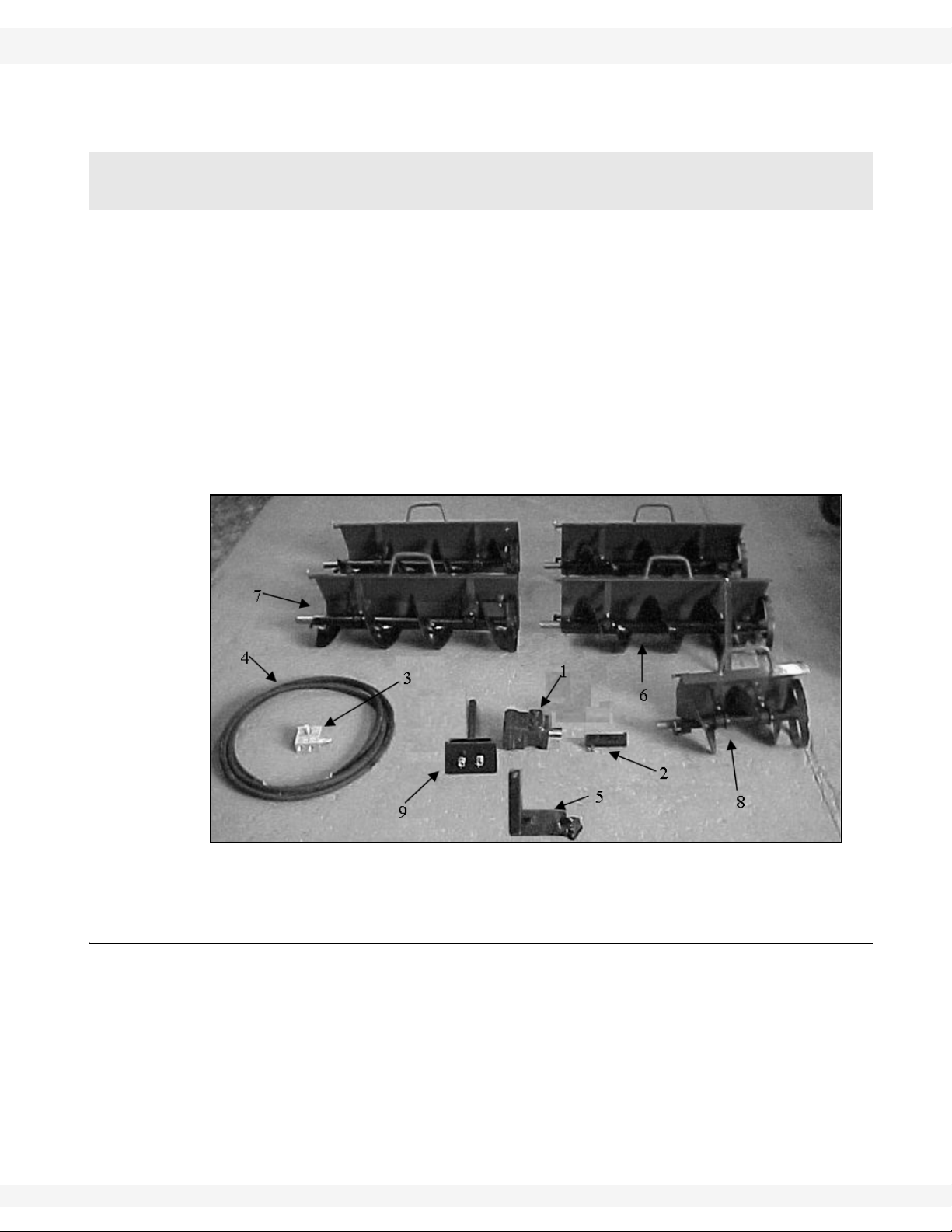
The In-Bin Sweep kit consists of (see Figure 1.1):
1. motor
2. motor coupler
3. relief valve
4. 2-16’ hoses
5. In-Bin pivot assembly
6. straight section with a walking shoe
7. three plain straight sections
8. 1-15” section
9. In–Bin Tower
Figure 1.1 In-Bin Super Sweep Kit (Total 11’3” Flighting in Kit)
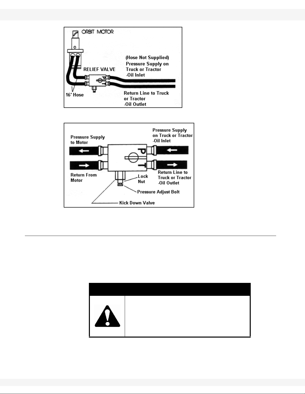
1.1. HYDRAULIC HOSE INSTALLATION
1. Connect hydraulic hoses between orbit motor and relief valve.
2. Quick couplers may be used on pressure “P” and return (“T” for tank) fittings
of the relief valve.
Note: System requires a minimum hydraulic source of 8 gpm at 1200 psi (see Figure
1.2 and 1.3).
IM5-R1 5
1. ASSEMBLY WHEATHEART - IN-BIN SUPER SWEEP
1.2. RELIEF VALVE INSTALLATION ALL MODELS
Figure 1.2 Schematic Drawing
Figure 1.3 Relief Valve
1.2. RELIEF VALVE INSTALLATION
1. The “P” on the relief valve must be connected to the “out” side of the pump
(see Figure 1.2 and 1.3) or directly to the “Pressure” source if using a remote
hydraulic source.
2. The “T” return or “tank” must be connected to the t ank or reservoir of the Bin
Sweep.
DANGER
Ensure that the return is connected to the tank
or reservoir of the Bin Sweep.
If it is not, the relief valve will not kick out and
serious injury or death can occur to the
operator.
3. If the motor turns the wrong way, first verify that the pressure and tank are
right, then try again. If motor still turns the wrong way, cross hydraulic lines
between valve and motor.
6 IM5-R1

WHEATHEART - IN-BIN SUPER SWEEP 1. ASSEMBLY
ALL MODELS 1.3. ASSEMBLY
1.3. ASSEMBLY
1. Mount tower over opening in floor and in the center of the bin.
2. Remove hairpin and slide pivot assembly down pivot shaft until it rests on the
collar. Mount motor to pivot assembly with 3/8” bolts.
3. Attach special motor coupler to hydraulic motor and then a straight bin sweep
section pinning in place. Add on extra straight sections as needed with the
last long section having the walking shoe. Add the 15” section to the end,
space permitting.
4. Make sure all sections are fully interlocked. The pins on the backboards fit
into the hole of the next section and the flighting sections line up to form one
continuous auger when twisted into place. (The welded finger on the end of
one section of flighting wraps around the spoke on the stationary wheel of the
next section.) (See Figure 1.4 and 1.5.)
Figure 1.4 In-Bin Tower and Pivot Assembly
IM5-R1 7

1. ASSEMBLY WHEATHEART - IN-BIN SUPER SWEEP
1.4. WHEEL MOVE OPTION ALL MODELS
Figure 1.5 Flighting and Backboard Assembly
5. Adjust collar until pivot assembly holds the first sweep section of flighting
about 1/8” off the floor (this is level).
6. The pivot assembly can be adjusted up to 10” horizontally in four different
positions by means of the two welded pegs and the welded cross pipes,
which can be swiveled 180°.
Note: In severe cases, extra walking shoes can be added to outer sections to prevent
tipping.
1.4. WHEEL MOVE OPTION
1. Assemble on flat surface.
2. Slide the outermost Supersweep backboard over the drivewheel alignment
pin and driveshaft.
3. Insert the hairpin to prevent the backboard from sliding back.
4. Place the backboard locking bracket against backboard and over the
backboard mount bracket.
5. Mark and drill the hole locations for bolting or welding the locking bracket to
the backboard.
8 IM5-R1

WHEATHEART - IN-BIN SUPER SWEEP 1. ASSEMBLY
ALL MODELS 1.4. WHEEL MOVE OPTION
Figure 1.6 Wheel Move Assembly
IM5-R1 9

1. ASSEMBLY WHEATHEART - IN-BIN SUPER SWEEP
1.4. WHEEL MOVE OPTION ALL MODELS
10 IM5-R1

WHEATHEART - IN-BIN SUPER SWEEP 2. OPERATION
Warning: Before continuing, please reread the safety information relevant to this section at the
beginning of this manual. Failure to follow the safety instructions can result in serious injury,
death, or property damage.
ALL MODELS
2.Operation
Important: The Super Sweep is an aggressive bin sweep, and when starting the sweep in
an in-bin situation, you must slowly lower the flighting down to the floor manually
with the backboard handle or the sweep will bury itself down into the grain,
kicking out the relief valve and shutting itself off. If this should occur, you will
have to dig the unit out by shovel.
NOTICE
Pulling the bin sweep out of buried grain by force could
damage flighting or alignment.
• The collar may have to be adjusted so the Super Sweep runs level. Too high
or too low will slow down the Super Sweep (see Figure 1.4).
• The rubber kicker on each section’s stationary wheel is adjustable – the further out, the more it drives the sweep forward into the pile. The kicker is
adjusted by placing or removing washers between the plate and the kicker
(see Figure 2.1).
Note: Do not adjust the kicker too far out as it will cause excessive wear on the kicker
and rough sweep operation.
In case of drag on bin sweep sections, check for build up of material around
bushings (ice, mud, etc.) or misalignment of welded bushing strut.
Some operators prefer to let the bin sweep run twice to reduce the center pile for
easier cleanup.
Figure 2.1 Rubber Kicker
IM5-R1 11

2. OPERATION WHEATHEART - IN-BIN SUPER SWEEP
ALL MODELS
12 IM5-R1

WHEATHEART - IN-BIN SUPER SWEEP 3. APPENDIX
ALL MODELS
3.Appendix
Figure 3.1 Wheel Move Components
IM5-R1 13

3. APPENDIX WHEATHEART - IN-BIN SUPER SWEEP
ALL MODELS
Parts List
No. Qty Description
1 1 Bin Sweep Wheel Drive
2 1 Top Wheel Driveshaft
3 1 Bottom Wheel Driveshaft
4 4 1/4” x 1” Woodruff Key
5 1 #40 Chain with Connector
6 1 Wheel Drive Axle
7 1 Sprocket Motor
8 7 1” Rim Washer
9 1 Small Drive Shield
10 1 Large Drive Shield
11 6 SMS, #14 x 5/8” With Washerhead
12 2 Bolt, 7/16” x 1” UNC GR5 PLD
13 1 5/16” x 1-1/2” Roll Pin
14 2 Nylon Chain Roller
15 2 Bolt, 5/16” x 2-1/2” UNC GR5 PLD
16 1 Bin Sweep Drive Wheel
17 1 Roller Chain, #40, 39”
18 1 Roller Chain, #40, Half Link
19 1 Roller Chain, #40, Single Link
20 1 Sprocket, with Hub, #40 54T, 1, Key
21 1 Sprocket, with Hub, #40 30T, 1, Key
22 1 Sprocket, with Hub, #40 13T, 1, Key
23 1 Driveshaft
24 2 Nut Nylock, 5/16” UNC GR5 PLT
25 2 Nut Hex, 5/16” UNC GR5 PLT
26 2 Nut Nylock, 7/16” UNC GR5 PLT
27 1 Shaft Spacer
14 IM5-R1

WARRANTY REGISTRATION
Wheatheart congratulates you on your new equipment purchase.
The warranty registration form must be filled out within thirty (30) days from delivery date and sent to:
Wheatheart Manufacturing
3455 Idylwyld Dr. N., Saskatoon, Saskatchewan S7L 6B5
CUSTOMER COPY
(Retain this card for warranty and record purposes.)
PRODUCT: DEALER’S NAME:
SERIAL #:
DELIVERY DATE:
OWNER’S NAME: PHONE #:
ADDRESS:
PHONE #:
DEALER COPY
(Retain this card for warranty and record purposes.)
PRODUCT: DEALER’S NAME:
SERIAL #:
DELIVERY DATE:
OWNER’S NAME: PHONE #:
ADDRESS:
PHONE #:
ADDRESS:
SIGNATURE:
INVOICE #:
(Please refer to invoice # when filing claim)
ADDRESS:
SIGNATURE:
INVOICE #:
(Please refer to invoice # when filing claim)
WARRANTY REGISTRATION
(Must be filled out and returned to Wheatheart within 30 days of delivery.)
OWNER’S NAME: DEALER’S NAME:
ADDRESS:
PHONE #: PHONE #:
SIGNATURE:
(I acknowledge the product to be whole and in
proper working order.)
PRODUCT: SERIAL #:
INVOICE #:
ADDRESS:
SIGNATURE:
(I acknowledge the product to be whole and in
proper working order. The owner has been given
an operation manual and has been informed on
proper operation and maintenance.)
DELIVERY DATE:
GAS MOTOR SERIAL #:


LIMITED WARRANTY
Wheatheart warrants to the buyer that the new machinery is free from defects in material and
workmanship.
This warranty is only effective for any new machinery that has not been altered, changed,
repaired, or treated since its delivery to the buyer, other than by Wheatheart or its authorized
dealers or employees, and does not apply to accessories, attachments, tools, or parts sold or
operated with the new machinery if they have not been manufactured by Wheatheart.
Wheatheart shall only be liable for defects in the material or workmanship attributed to faulty
material or bad workmanship that can be proved by the buyer, and specifically excludes liability
for repairs arising as a result of normal wear and tear of the new machinery or in any other manner whatsoever, and without limiting the generality of the foregoing, excludes application or
installation of parts not completed in accordance with Wheatheart operation manual, specifications, or printed instructions.
A Warranty Registration Form and Inspection Report must be completed at the time of delivery
and returned to Wheatheart Manufacturing within thirty (30) days.
Warranty Period
Private Farm Use One (1) year from date of purchase.
Commercial, Custom, or Rental Use Ninety (90) days from date of purchase.
Replacement Parts Ninety (90) days from date of replacement
Defective parts are subject to inspection by a Wheatheart representative prior to approval of a
warranty claim. All returned parts must be sent to the factory, freight pre-paid, in order to qualify
for warranty replacement. Repaired or replaced parts will be returned freight collect.
If these conditions are fulfilled, Wheatheart shall at its own cost and its own option either repair
or replace any defective parts provided that the buyer shall be responsible for all expenses
incurred as a result of repairs, labor , part s, transporta tion, or any other work, unless Wheatheart
has authorized such expenses in advance. Normal wear and service items such as belts,
hoses, flashing, etc. are excluded from warranty.
The warranty shall not extend to any repairs, changes, alterations, or replacements made to the
new equipment other than by Wheatheart or its authorized dealers or employees.
This warranty extends only to the original owner of the new equipment.
This warranty is limited to the terms stated herein and is in lieu of any other warranties whether
expressed or implied, and without limiting the generality of the foregoing, excluded all warranties, expressed or implied, or conditions whether statutory or otherwise as to quality and fitness
for any purpose of the new equipment, Wheatheart disclaims all liability for incidental or consequential damages.
This machine is subject to design changes and Wheatheart shall not be required to retro-fit or
exchange items on previously sold units except at its own option.
WARRANTY VOID IF NOT REGISTERED

Wheatheart
Part of the Ag Growth International Inc. Group
3455 Idylwyld Drive North
Saskatoon, Saskatchewan, Canada
Phone: (306) 934-0611
Fax: (306) 934-6020
Toll Free: (877) 934-0649 (Canada & USA)
website: www.wheatheart.com
email: sales@wheatheart.com
© Ag Growth International Inc. 2013
Printed in Canada
 Loading...