

Part Number: 30735 R1
Revised: Aug/14
Read this manual before using product. Failure
to follow instructions and safety precautions can
result in serious injury, death, or property
damage. Keep manual for future reference.
INTAKE HOPPER
BH/GHR AUGERS
OPERATOR AND ASSEMBLY MANUAL

This product has been designed and constructed according to general engineering
standardsa. Other local regulations may apply and must be followed by the operator.
We strongly recommend that all personnel associated with this equipment be trained
in the correct operational and safety procedures required for this product. Periodic
reviews of this manual with all employees should be standard practice. For your
convenience, we include this sign-off sheet so you can record your periodic reviews.
Date Employee Signature Employer Signature
a. Standards include organizations such as the American Society of Agricultural and Biological Engineers,
American National Standards Institute, Canadian Standards Association, International Organization for
Standardization, EN Standards, and/or others.

WHEATHEART - INTAKE HOPPER
BH/GHR AUGERS
TABLE OF CONTENTS
1. Safety .................................................................................................................................... 5
1.1. Safety Decals........................................................................................................... 5
1.1.1. Decal Installation/Replacement.................................................................. 5
1.1.2. Safety Decal Locations and Details............................................................ 5
2. Assembly .............................................................................................................................. 7
2.1. Tube Clamps and Transition Flight Assembly.......................................................... 7
2.2. Transition Assembly................................................................................................. 8
2.3. Attaching the Hopper.............................................................................................. 10
2.4. Tow Bar and Transport Channel............................................................................ 11
3. Operation, Transport, & Maintenance.............................................................................. 13
3.1. Operating Procedure.............................................................................................. 13
3.2. Transport Procedure .............................................................................................. 14
3.3. Maintenance Procedures ....................................................................................... 16
Limited Warranty..................................................................................................................... 17
30735 R1 3

WHEATHEART - INTAKE HOPPER
BH/GHR AUGERS
4 30735 R1

WHEATHEART - INTAKE HOPPER 1. SAFETY
BH/GHR AUGERS 1.1. SAFETY DECALS
1.Safety
Refer to your auger manual for complete safety instructions.
1.1. SAFETY DECALS
• Keep safety decals clean and legible at all times.
• Replace safety decals that are missing or have become illegible. See decal
location figures that follow.
• Replaced parts must display the same decal(s) as the original part.
• Replacement safety decals are available free of charge from your distributor,
dealer, or factory.
1.1.1. DECAL INSTALLATION/REPLACEMENT
1. Decal area must be clean and dry, with a temperature above 50°F (10°C).
2. Decide on the exact position before you remove the backing paper.
3. Align the decal over the specified area and carefully press the small portion
with the exposed sticky backing in place.
4. Slowly peel back the remaining paper and carefully smooth the remaining
portion of the decal in place.
5. Small air pockets can be pierced with a pin and smoothed out using the sign
backing paper.
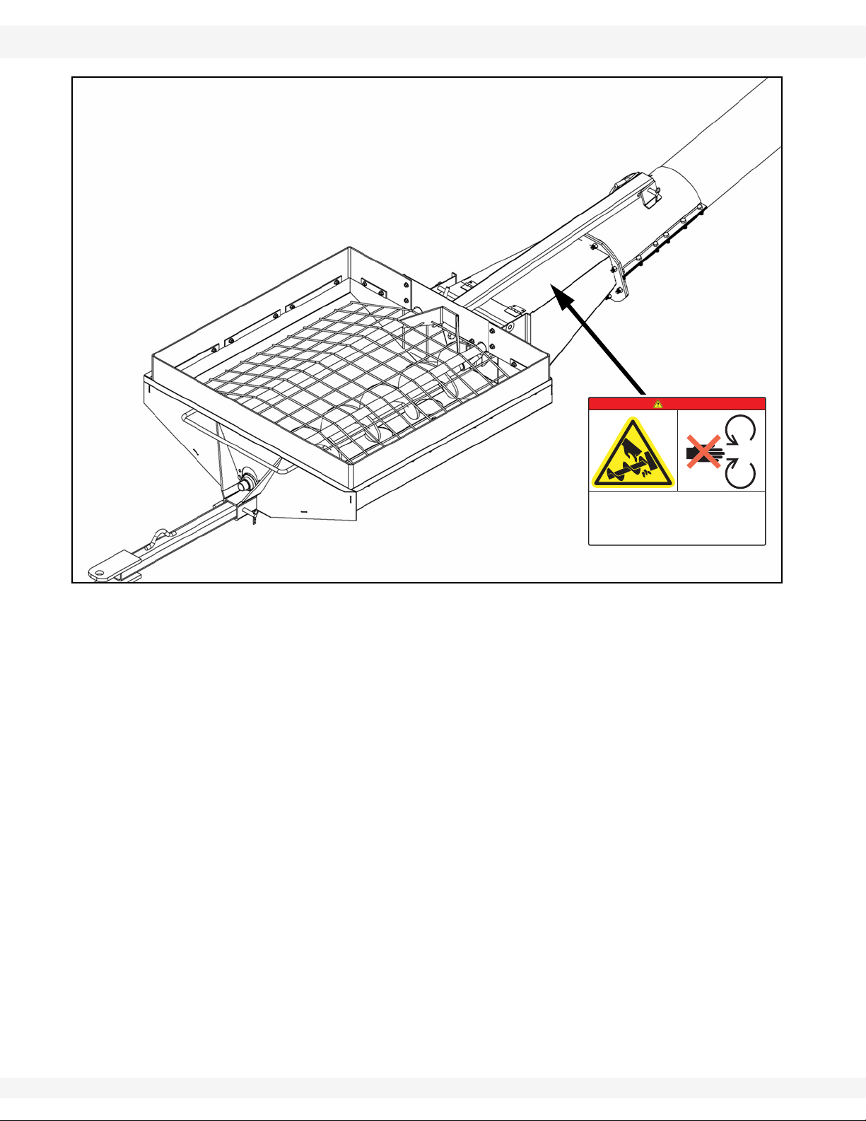
1.1.2. SAFETY DECAL LOCATIONS AND DETAILS
Replicas of the safety decals that are attached to the equipment and their
messages are shown in the figure(s) that follow. Safe operation of the equipment
requires that you familiarize yourself with the various safety decals and the areas
or particular functions that the decals apply to, as well as the safety precautions
that must be taken to avoid serious injury, death, or damage.
30735 R1 5
1. SAFETY WHEATHEART - INTAKE HOPPER
DECAL 20813
DANGER
ROTATING FLIGHTING HAZARD
To prevent death or serious injury:
• KEEP AWAY from rotating auger flighting.
• DO NOT remove or modify auger flighting
guards, doors, or covers. Keep in good
working order. Have replaced if damaged.
• DO NOT operate the auger without all
guards, doors, and covers in place.
• NEVER touch the auger flighting. Use a
stick or other tool to remove an
obstruction or clean out.
• Shut off and lock out power to adjust,
service, or clean.
20813
Made in Canada
1.1. SAFETY DECALS BH/GHR AUGERS
Figure 1.1
6 30735 R1

WHEATHEART - INTAKE HOPPER 2. ASSEMBLY
WARNING Before continuing, ensure you have read and underst and the relevant information
in the safety section. Safety information is provided to help prevent serious injury, death, or
property damage.
BH/GHR AUGERS 2.1. TUBE CLAMPS AND TRANSITION FLIGHT ASSEMBLY
2.Assembly
Important: T o make assembly process as convenient as possible, use of a lif t crane or some
other equipment for lifting the lower tube of the auger is recommended. Support
discharge end of auger to prevent upending.
2.1. TUBE CLAMPS AND TRANSITION FLIGHT ASSEMBLY
Figure 2.1
1. For Retrofits: First remove existing flighting guard and transition flighting.
2. Connect top and bottom tube clamp on lower tube with twelve 7/16" x 1-1/4"
bolts and locknuts, tighten securely.
Note: Line tube clamp flange flush with end of lower tube.
30735 R1 7

2. ASSEMBLY WHEATHEART - INTAKE HOPPER
2.2. TRANSITION ASSEMBLY BH/GHR AUGERS
3. The top tube clamp has a slot to fit around the handle, which is already
welded on the tube.
4. Take the transition flight and slide it onto the lower flight.
5. For continuous flow, make sure that the ends of the lower flight and the
transition flight are butting together. See Figure 2.2.
Figure 2.2
6. Spin the flight to line up hole on transition flight with the hole in the lower flight
tube.
7. Insert 3/8" x 2-1/2" bolt for 8" augers, or 3/8" x 3-1/4" bolt for 10" augers,
1/2” x 4-1/2” for 13” augers and tighten locknut.
2.2. TRANSITION ASSEMBLY
1. Using a lift crane or other lifting equipment, lift lower tube up to a comfort able
working height.
2. Make sure transition is vertical to tube. See Figure 2.4.
8 30735 R1

WHEATHEART - INTAKE HOPPER 2. ASSEMBLY
RIGHT WRONG
BH/GHR AUGERS 2.2. TRANSITION ASSEMBLY
Figure 2.3
Figure 2.4
30735 R1 9

2. ASSEMBLY WHEATHEART - INTAKE HOPPER
TOP TUBE CLAMP
2.3. ATTACHING THE HOPPER BH/GHR AUGERS
2.3. ATTACHING THE HOPPER
Figure 2.5
1. Clean dirt from inside u-joint on hopper and off of lower flight shaft. Insert
woodruff key into lower flight. See Figure 2.5.
2. Open service door on transition, then bring transition and hopper together,
guiding flight shaft into u-joint.
3. Attach transition to the hopper with two 5/8" x 1-1/2" bolts and locknuts. Do
not over-tighten. Tighten snug only; these bolts act as pivot points. Use top
hole on hopper for 10" auger or bottom hole for 8" auger.
4. Tighten set screws on u-joint, then close and secure the service door with the
provided door pin (see Figure 2.6).
5. Tighten tube clamps.
6. Install rubber extension inside of the hopper with:
• For 8” and 10”: twenty-six 5/16" x 3/4" bolts and whiznuts, and eight
medium (10") and three short (4-3/4") belting straps.
• For 13”: twenty-eight 5/16" x 3/4" bolts and whiznuts, seven medium (10")
and two long and two short (4-3/4") belting straps.
10 30735 R1

WHEATHEART - INTAKE HOPPER 2. ASSEMBLY
BH/GHR AUGERS 2.4. TOW BAR AND TRANSPORT CHANNEL
2.4. TOW BAR AND TRANSPORT CHANNEL
Figure 2.6
1. Attach transport channel to hopper with a saddle pin and secure with snap
pin.
2. Attach other end of transport channel (with 4-hole pattern) to top tube clamp
on lower tube in a convenient location. Use snap pin to secure saddle pin.
3. Slide the tow bar into the hitch tube of hopper and secure with a saddle pin
and grip clip.
30735 R1 11

2. ASSEMBLY WHEATHEART - INTAKE HOPPER
2.4. TOW BAR AND TRANSPORT CHANNEL BH/GHR AUGERS
12 30735 R1

WHEATHEART - INTAKE HOPPER 3. OPERATION, TRANSPORT, & MAINTENANCE
BH/GHR AUGERS 3.1. OPERATING PROCEDURE
3.Operation, Transport, & Maintenance
3.1. OPERATING PROCEDURE
Figure 3.1
1. For other auger-related placement instructions, please refer to your auger
operation manual.
2. Remove tow bar from hopper. Place auger/hopper in desired location (for
example, under a bin hopper). See Placement instructions in auger operator
manual.
3. Set the hopper to self-level by disconnecting transport channel at top end.
4. To clean out after use, remove the cleanout cover by removing the four 5/16”
nuts holding it in place and use a vacuum or other tool to clean out.
30735 R1 13

3. OPERATION, TRANSPORT, & MAINTENANCE WHEATHEART - INTAKE HOPPER
3.2. TRANSPORT PROCEDURE BH/GHR AUGERS
3.2. TRANSPORT PROCEDURE
Figure 3.2
1. Place auger in full down position. The roller track shoe should be seated
against the upper track stop with slight tension on the lift cable. Refer to
auger operation manual for further instructions.
2. Attach transport channel and tow bar. See steps 2 and 3 under “Tow Bar and
Transport Channel” on page 11.
3. Place and secure hitch pin and safety chain. The safety chain should be
threaded though handle on the lower tube and wrapped around auger tube
before attaching to the towing vehicle (Figure 3.2).
4. Connect the stabilizer bar to hole number one and secure with saddle pin
and snap pin.
Important: Use a type of hitch pin that will not allow auger to separate from towing vehicle.
5. Beware of overhead obstructions and electrical wires. These augers have a
minimum clearance from 7’6” to 15'6” (2.29 m to 4.72 m).
14 30735 R1

WHEATHEART - INTAKE HOPPER 3. OPERATION, TRANSPORT, & MAINTENANCE
BH/GHR AUGERS 3.2. TRANSPORT PROCEDURE
Figure 3.3
30735 R1 15

3. OPERATION, TRANSPORT, & MAINTENANCE WHEATHEART - INTAKE HOPPER
3.3. MAINTENANCE PROCEDURES BH/GHR AUGERS
Figure 3.4
IF MOVING AUGER BETWEEN BINS:
1. Ensure auger is empty and lower auger until stabilizer bar can be secured in
one of the holes with saddle pin and snap pin. Slowly move to only to an
adjacent bin. Or alternatively, if it is not possible to lower the auger, lift the
hopper and have a second person align and secure the stabilizer bar.
2. If required, re-attach tow bar to auger and move with tractor. Refer to Figure
3.2.
3. Remove tow bar and position auger in desired location.
4. Disconnect stabilizer bar at top end and place saddle pin back through hole
and secure with hairpin.
3.3. MAINTENANCE PROCEDURES
1. Frequently, or every eight hours of operation, open service door and grease
bushing the u-joint. Close door.
16 30735 R1

LIMITED WARRANTY
Wheatheart warrants to the buyer that the new machinery is free from defects in material and workmanship.
This warranty is only effective for any new machinery that has not been altered, changed, repaired, or
treated since its delivery to the buyer, other than by Wheatheart or its authorized dealers or employees, and does not apply to accessories, attachments, tools, or parts sold or operated with the new
machinery if they have not been manufactured by Wheatheart.
Wheatheart shall only be liable for defects in the material or workmanship attributed to faulty material
or bad workmanship that can be proved by the buyer, and specifically excludes liability for rep airs arising as a result of normal wear and tear of the new machinery or in any other manner whatsoever, and
without limiting the generality of the foregoing, excludes application or installation of parts not completed in accordance with Wheatheart operation manual, specifications, or printed instructions.
A Warranty Registration Form and Inspection Report must be completed at the time of delivery and
returned to Wheatheart Manufacturing within thirty (30) days.
Warranty Period
Private Farm Use One (1) year from date of purchase.
Commercial, Custom, or Rental Use Ninety (90) days from date of purchase.
Replacement Parts Ninety (90) days from date of replacement
Defective parts are subject to inspection by a Wheatheart representative prior to approval of a warranty claim. All returned parts must be sent to the factory, freight pre-paid, in order to qualify for warranty replacement. Repaired or replaced parts will be returned freight collect.
If these conditions are fulfilled, Wheatheart shall at its own cost and its own option either repair or
replace any defective parts provided that the buyer shall be responsible for all expenses incurred as a
result of repairs, labor , parts, transport ation, or any other work, unless Wheatheart has authorized such
expenses in advance. Normal wear and service items such as belts, hoses, flashing, etc. are excluded
from warranty.
The warranty shall not extend to any repairs, changes, alterations, or replacements made to the new
equipment other than by Wheatheart or its authorized dealers or employees.
This warranty extends only to the original owner of the new equipment.
This warranty is limited to the terms stated herein and is in lieu of any other warranties whether
expressed or implied, and without limiting the generality of the foregoing, excluded all warranties,
expressed or implied, or conditions whether statutory or otherwise as to quality and fitness for any purpose of the new equipment, Wheatheart disclaims all liability for incidental or consequential damages.
This machine is subject to design changes and Wheatheart shall not be required to retro-fit or
exchange items on previously sold units except at its own option.
WARRANTY VOID IF NOT REGISTERED

Part of the Ag Growth International Inc. Group
P.O. Box 39
Rosenort, Manitoba, Canada R0G 1W0
Phone: (866) 467-7207 (Canada & USA)
Fax: (866) 768-4852
Website: www.wheatheart.com
Email: sales@wheatheart.com
© Ag Growth International Inc. 2014
Printed in Canada
 Loading...