

Page 1
CONTACT 502A
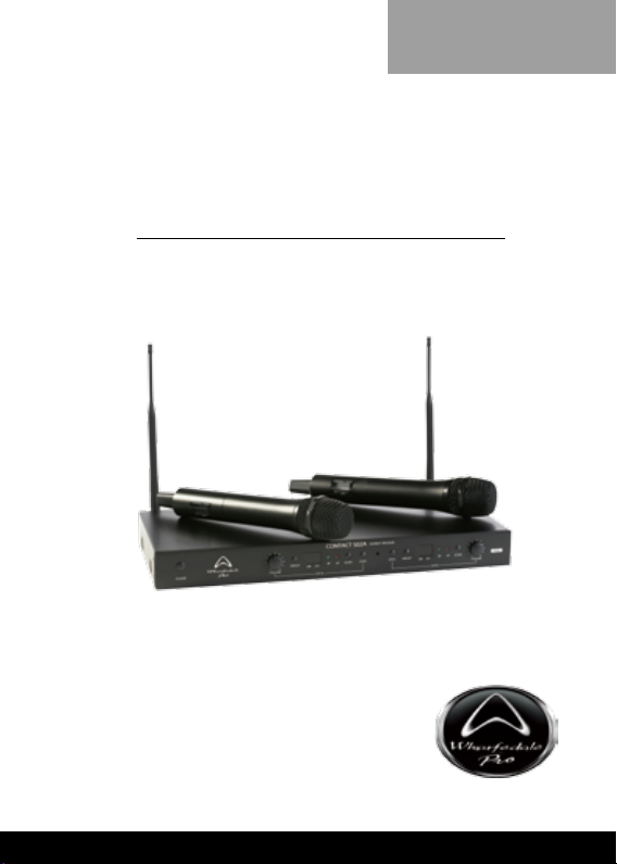
Wireless Microphone System
OPERATING MANUAL AND USER GUIDE
ww w.whar fedalep ro.com
Page 2

OPERATING MANUAL
IMPORTANT WARNINGS & SAFETY INSTRUCTIONS
1. Please re ad and reta in these safety instructio ns.
2. Heed a ll warn ings in the oper ating i nstr ucti ons and o n t he
3. Do not use t his appara tus near wate r or moistu re.
4. Clean onl y with a dr y cloth.
5. Do not install near sources of heat su ch as radi ators , h eat
6. Refer all servicing to authorised per sonnel.
7. The re are no us er servic ea ble p ar ts insi de t hi s pro duct.
8. Serv icing is r equired when the apparatus has been damaged
9. To completely disconn ect t his eq uipment from the AC main s
10. To p revent fir e never p lace t he uni t near any naked f lam e
11. Do not defeat t he purp ose of the polarized o r grounding ty pe
12. USIN G A MPLIFIERS – In o rder to avoid da mage to drive rs
applian ce.
registe rs, stoves o r other appa ratus that p roduce he at.
User s s hould not attemp t to servi ce this product . Warran ty
nullication c ould result if this is at tempted.
in any way incl udi ng: Impact damag e, power cord/su ppl y
damage, liquid spillages, s mall o bjects falling into the unit or
exposu re t o mo isture. In addition please r efer to author ised
service pers onnel if the apparatus is not opera ting normally.
discon nect the power plug fr om the AC rec eptacle.
such as a candle.
plug . A polar ized plug has two b lade s w ith one w ider than
the other. A gro unding type plu g has tw o blades and a thi rd
groundi ng prong. The w ide blad e or the third prong ar e there
for your s afety. If th e plug doe s not t int o your outl et, consult
an elect rician for replac ement of the o bsolete ou tlet.
and other equi pment, it is advisable to establish and fol low a
routine for p owering up and power ing dow n a so und syst em.
Wi th all sys te m co mp on ent s c on nec ted, tur n o n sour ce
equip ment (mixer s, s ignal process ors, record and playback
1
Page 3

Contact 502A
un it s, etc .) B EFOR E p ower ing up amp li fi ers. Trans ient
volt ages f rom powerin g u p sourc e equi pment c an dama ge
speaker s if ampliers are already turned on. Make sur e that
amp li fi er volu mes are set t o thei r minim um settin gs and
powe r up any system amplif ier s L AST. It i s r eco mmen ded
that all sys tem components be allowed to sta bilize for s everal
sec onds before any s ourc e signa ls are introd uced or l evel
se tt in g ad ju stmen ts ar e ma de . Si mi la rl y, when shu ttin g
syste ms down , t urn all a mplifier s off first, before poweri ng
down any other system component s.
13. CAB LES – D o not use shielde d or micro phon e cab les for
co nn ec ti on bet ween amp lif ier s a nd spe aker s. Use on ly
approved speaker ca bles with p roper co nnector s.
14. RI GG IN G – SU SP EN DI NG – MOUN TIN G – R ig gin g,
susp endi ng and mounti ng of speaker systems can expo se
me mbe rs of the pub lic to ser io us hea lt h ri sk s an d ev en
de ath . UN DE R NO CI RCU MSTANC ES ATT EMP T TO
R IG , SU SP EN D OR OT H ERW IS E MO UN T SO UN D
REINFO RCEMENT PRODU CTS UN LESS YOU ARE FULLY
QUA LIF IED AND CERTIFIE D TO DO S O BY RELEVA NT
L O C A L, ST AT E A ND NA TI ON A L AU T H OR IT I E S .
A LL RE LE VAN T SA FE TY R EG UL AT ION S MUS T BE
FOL LOW ED. I F YOU AR E NOT P RO PER LY QUA LIF IED
OR DO N OT KN OW OF PER TI NEN T REG ULA TI ON S,
CONSU LT QUALIFIED PER SONNEL FO R ADVICE .
15. CAU TION – Prof es si on al sou nd reinf or ce me nt sys te ms
are capa ble of gener ating very high soun d pressur e l evels.
Take c are with p lacement and operati on to avoid exposure
to excessive volume levels. Permanent he aring damage can
result when operat ed to extreme levels.
2
Page 4

OPERATING MANUAL
TABLE OF CONTENTS
Impor tant Warnings and Safety Instructions ........................ 1
Introduction ............................................................................4
Overv iew ................................................................................ 4
Features and contents ...........................................................
Settin g up the rece iver
Receiver operation ................................................................
Receiver controls ...................................................................9
Placement of the Receiver ..................................................
Notice ................................................................................... 11
Names and Functions ..........................................................
Batter y installation ...............................................................
Specication ........................................................................ 13
Warrant y............................................................................... 14
5
........................................................... 8
9
10
11
12
3
Page 5

Contact 502A
INTRODUCTION
Wh ar fe dale Cont ac t 502 A Wire le ss mic ropho ne s are the
res ult o f many yea rs of experi enc e in the us e, de sig n and
manufactu ring of pr ofessional a udio product s.We take great
pr id e in engi ne er ing and bu il di ng eve r y Wharf ed al e Pro
microphone and wish to thank you for entrusting us with your
sound.
Please take a few minutes to read this manual completely in
order to ensure that you get the most out of your Contac t 502A
Wireless microphone.
CONTACT 502A OVERVIEW:
Thank you for sele cting the Cont act 502A dual-channel UHF
wireless microphone system. This system can receive signals
from two micr ophones simultaneously. It uses digital circuitry
to disting uish the intensity of the signals receive d by the two
antennas.
Eac h channel has a vol ume co ntr ol, funct io n bu ttons and
is cont ro lle d by a dedic ate d CPU. An LED dis play Shows
in fo rm at ion for eac h cha nn el . Func tion but to ns in cl ud e:
GROUP, SCAN and SYNC.
Th e SYN C but to n al l ow s t he us er to qui c kly lo ck t h e
recei ving and transmi tt ing frequ enc ie s of the mic ropho ne
transmi tter system. The Contact 502A can seamlessly change
frequenc ies quickly and sele ct compatible channel s without
th e ne ed to mut e mixe r chan ne ls or out put de vi ce s. The
Contac t 502A is packaged in a 1U rack mount chassis.
4
Page 6

OPERATING MANUAL
FEATURES
• Antenna diversity system with 2 antennas
• High sensitivit y handheld dynamic mic rophones with
integrated transmitters
• Infrared link for automatic sync hronisation of transmitter s
and receiver
• Automatic scannin g for inter ference free channels
• Intelligent battery status display for each channel
• Up to 8 hours of continuous use from 2x AA bat teries
• Automatic microphone off in l ow batter y conditions
• Worldwide multi-voltage switching p ower supply
CONTENTS
1 x Wireless receiver
2 x Antennas
2 x Dynamic micropho nes with built in transmitters
2 x ¼” jack cables
1 x Power supply
1 x User manual
4 x AA bat teries
1 x Rack mount kit
5
Page 7

Contact 502A
FRONT PANEL O F THE DUAL CH ANNEL RECEIVE R:
Fig.1
1) POWER: Toggles the power on and off.
2) VOLUME CONT ROL (Channels A & B): Sets the leve l
for each channel.
3) G R O UP ( C h a nn el s A & B ) : Cr ea t e gr ou p s of
microphone s, which is us eful when many micro phone s
are used simultaneously.
4) LE D (Cha nn els A & B): Di sp lay s the GRO UP and
CHANNEL assignment for each channel.
5) RF LED (C hannels A & B): Indicates that RF sig nal is
present and locked.
6) AF LED (Channels A & B): Indicates that audio signal is
present .
7) SCA N (Channel s A & B): Ini tiates scanni ng for a new
channel. Automatically scans and locks on to compatible
interference free channels.
8) SYNC (Channels A & B): Synchronises the transmitter to
the rece iver.
9) IR SYN C receiver: Recei ves the I R SYNC signal from
the base of the transmi tter.
10) Receiver Frequency Codes. (See page 14,
Frequency R ange Code Table)
11) Rack ears: Used to fi x the r eceiver to a s tandard 19 ’’
equipment rack.
III
6
Page 8

OPERATING MANUAL
REAR PANEL OF THE DUAL CHANNE L RECEIV ER:
12) Antenna C onnectors
13) Output B: ¼” unbalanced jack output connector for CH B.
14) OUT PUT MO DE S wit ch: Us e “ MI XE D ” to ou tp ut
15) Output A : ¼” unbalanced jack output c onnector for CH A
16) Outpu t Level Sw itch: Use “M IC ” when conne ct ed to
17) LO CK: W he n en ga ged all fro nt pan el but t on s ar e
18) SQU ELC H B: Adjus ts the se nsi tiv it y of Chann el B t o
19) SQU ELC H A: A dju sts the sens iti vit y of C han nel A to
20) DC Po we r rec ep ta cle: Fo r con nec ti ng th e ext er na l
Fig.2
both microp ho nes fr om out pu t A . Us e “ SEPAR ATE ”
to output each microphone individually.
or the mixed signal.
mic rop hon e inputs (-14dBv/ 100Ω). U se “LIN E” when
connec ted to line leve l inputs (+4dBv/ 5kΩ).
disabled. The power switch will continue to function even
when the unit is locked.
reduce noise.
reduce noise.
13V DC power supply (centre pin positive).
7
Page 9

Contact 502A
SETTING UP THE RECEIVER
Output conne ction:
Fig.3
Fig.3a
1. Ins tall the two antennas on the rear panel as sh own in
Fig.3a.
2. Connect the power supply as shown in Fig.3 . (Caution:
Ensure the power supply has the correct rating for your
local AC supply)
3. Co nnect aud io leads fr om the o utput of each cha nnel
to an input on a mixer or powered speaker. When t he
output cable is c onne cte d to an auxiliary o r line i nput
the “OUTPUT LEVEL” switc h (16) should be set to the
“LINE” p osition. W hen the output cable is connecte d to
a m icrophone input of a mixer or powe red louds peaker
th e “O UT PU T LE VEL” swi tch sh oul d be set to the
“MIC ” position. If the “LEVEL” switc h is set in the wrong
position the gain structure will be wrong and can cause
excessive hiss or distortion.
4. When the “OUTPUT MODE” switch (14) is set to “MIXED”
only con nect to “O UTP UT A” (13). There is n o out put
from “OUTPUT B” in this mode.
8
Page 10

OPERATING MANUAL
RECEIVER OPERATION:
1 Be f or e tu rni ng on t he rec eiv e r, ma ke ce r ta in th e
2. Turn on the wire less microph one. T he RF indicator light
RECEIVER CONTROLS
1. Upon power up the LED fully illuminates and displays the
2. G RO U P fun c ti on: Pr es s th e GRO UP but ton on c e.
3. CH ANNEL f unction: press the SCAN button once. The
4. SYNC func tion: Press the SYNC button once and move
transmitter is off. Also ensure that the volume for CH A
and CH B are set to minimum. Ensure that you r output
device s are muted or set to the lowe st possi ble level
bef ore tur nin g on the Contact 5 02 A, the n hold down
the power button of the receiver until the LED displ ays
illuminate.
of th e cor res pon ding chan nel will illumi nate . Turn the
volume of t he receiver to 12 o’clock. Raise the level o f
your output devices and then speak into the microphone.
The AF indic ator LED on the receiver will illuminate with
the volume level.
GROUP and CHANNEL information.
The grou p n umber will ash; it shows that the GROU P
is pending. Pre ss the Group but ton to increme nt the
GROUP numbers from 1-9. Stop at the desired number
to assign to the group.
channel numbers ash showing the channel is pending.
Pre ss it a gai n to incre ment the n umb ers . Sto p at the
desired number to assign the channel.
the powered -up microphone about 30 cm in front of the
rec eiver. Poin t the p ower indi cator of the mic rophone
at the transmit tin g wi ndo w of the re cei ver. When t he
chann el loc ks , th e LCD will dis pl ay the same gr oup
and cha nne l as the re ceiver. Syn chr oni satio n is now
complete.
9
Page 11

Contact 502A
Fig.5
5. LOCK and UNLOC K: If you wish to lock the controls on
the front panel to avoid accidental adjust ments, set the
“LOCK /UNLOCK” switch (17) to the “LOC K” position. All
the buttons will be disabled except the “POWER ” button.
To enable the fro nt panel contr ols slide the switch to the
“UNLOCK” position.
6. SQUELCH: There are two adjustable SQUELCH controls
on the rear panel of the rec eiver. The SQUELCH value
of the A and B channel should be adjusted to improve
soun d quali ty, and can be used to minim ise unwanted
hiss or distrortion.
PLACEMENT OF THE RECEIVER
1. In order to achieve the best results, t he receiver shoul d
Have a m inimum 1 me tre clear anc e on all side s fro m
the oor or walls. The distance between the tr ansmitter
and ante nna shou ld be over 1 metre, as in Fig. 4. The
receiver shoul d b e kept away from sources of pos sible
interference.
Fig.4
2. The receiver can be mounted in a EIA standard 19 inch
(482.6mm) rack. Use the supplied rack ears as per Fig. 5.
10
Page 12

OPERATING MANUAL
Fig.6
NOTICE:
• The pos iti on of the anten na will affe ct the re ception,
• Se veral sets of wi re le ss mi cr op ho nes can be us ed
NAMES AND FUNCTIONS:
1. Pop sh ie ld : Pro te ct s the mi c ro ph on e cap sule fro m
2. Bar rel: Contains the transmitter circuitry.
3. Bat tery Co mpartment: houses two A A type bat teries.
4. Transmit ter codes.
5. LCD panel: Displays the transmitter information.
6. SYNC signal IR transmitter: transmits SYN C information,
so minimise the dist ance bet ween the microphone and
receiver where pos sible.
sim ult ane ous ly with this system . Ple ase con sul t your
dealer or distributor for cor rect fre quencies.
dam age and reduces th e “po p” noise (from “ P’s ” and
“B's”) as well as wind noise.
self-adjusts frequency and transmit ting power.
11
Page 13

Contact 502A
BATTERY INSTALLATION
Fig.7
1 Un sc re w the upp er pa r t (2) of th e mic ro ph on e in a
counter- clock wise direction
2. Install the two AA batteries acc ording to the polarity as
shown in the batter y compartment, and screw the upp er
part tight.
3. Operating Functions of the LCD Panel
1) When th e powe r swit ch is in posi ti on 1, the LCD
displays all the c ontent, then displays the p ower value
for a second.
2) Ba t te r y Sta tus : Whe n th e bat ter y le ve l is 10% ,
batteries should be r eplaced. When the battery level is
0%, the LCD battery level and the power supply indic ator
wil l fl ash to remin d you aga in to cha nge bat ter ies. If
the batter y level is too low for a long time, the LCD will
display “ Po OFF” and turn off the microphone.
4. Turnof f:
1) W hen the power supply is switched to “O ”, the LCD
will display “Po OFF”, whic h indicates it will turn off soon,
and then the power supply will autom atically shut down.
12
Page 14

OPERATING MANUAL
NOTE: When the microphone is not in use, remember to turn
off the power supply. If you will not use the microphone for a
long time, remove the batteries to avoid damage from battery
leakag e. I f yo u are using recha rgeable batteri es, remove the
batter ies and charge them in their charger.
SPECIFICATIONS
I. Rece iver
Cabinet S ize EIA Stan dard 1U
Channel s Two Channel
Receiv ing Manne r Automat ic via Ante nna
Oscill ation Mode
Carri er Frequenc y Range UHF 529 ~865MHz
Stabil ity ±0.00 5%(-10~50 º C)
Bandwi dth 13MHz
Sensit ivity 4μV (S/N>12dB 25 KHz deviation)
Frequenc y Interva l
Switch ed Frequenc ies 50 chann el
S/N ≤90 dB(A)
T.H.D. < 1% at 1KHz
Frequenc y Response 60 - 15KHz (± 3dB)
Functional Distance 80 meter s Line of Sight
Max. Ou tput Level -14dBV/5 kΩ
Output J ack 6.3mm (1/4”) Phone jack
AC Power Supp ly Exter nal 110-220VAC
DC Power Supply 0.5A, 13 - 15VDC
Dimensions (mm) 420 x 195 x 44mm
PLL (Phas e Locked Loo p),
freque ncy compounded.
250K Hz
No te : Ac tu al r an ge d ep en ds on R F
sig nal absor ption , re flec tion and
interf erence.
13
Page 15

II. Transmitter
Oscill ation Mode
Carri er freque ncy
Frequenc y Stabili ty
Bandwi dth
Frequenc y Adjustme nt
Output Power
Harmo nic radiat ion
Max. ad justment r ange
Max. In put SPL
Batter y
PLL (Phas e Locked Loo p)
freque ncy Compo unded
UHF 529 ~ 8 65MHz
±0.00 5% (-10 ~ 50 ºC)
13MHz
Automat ic Channel s etting
> 10dBm (adju stable)
< 55 dB(c)
± 48kHz
140dB
AA bat tery x 2
III. Fre quency Range Code Table.
Receiving
Frequency R anges
Code Frequency
Range(M Hz)
F1 529 – 596
F2 659 – 69 6
F3 713 – 752
F4 780 – 806
F5 838 – 865
Transmitting
Frequency
Ranges
Code Frequency
Range(M Hz)
F1A 529 – 542
F2A 659 – 662
F3A 713 – 726
F4A 780 – 793
F5A 838 – 841
Transmitting
Frequency
Ranges
Code Frequency
Range(M Hz)
F1B 583 – 596
F2B 683 – 6 96
F3B 740 – 752
F4B 793 – 80 6
F5B 852 – 86 5
WHARFEDALE PRO LIMITED WARRANTY
Whar fedale Pro C onta ct 502 A Wire less Micro phone S ystem s
are w arranted of manufac turing or material defects fo r a period
of one year from the o rigin al date of purchase. In the event of
malfun ction, contact your auth orise d Wh arfed ale Pro dealer or
distri butor for in formati on.
* Be awar e tha t warra nty det ail s may d if fer fro m co unt ry to
co unt ry. Co nta ct you r de ale rs or dist ri but or f or i nf ormat ion.
These terms do not infringe your statuto ry rights.
Contact 502A
14
Page 16

IAG House, 13/14 Glebe Road, Huntingdon, Cambridgeshire,
Wharfedale Professional reserves the right to alter
Wharfedale Professional
PE29 7DL, UK
www.wharfedalepro.com
or improve speciications without notice.
All rights reserved © 2010 Wharfedale Pro.
Wharfedale Pro is a member of the IAG Group.
 Loading...