

Page 1
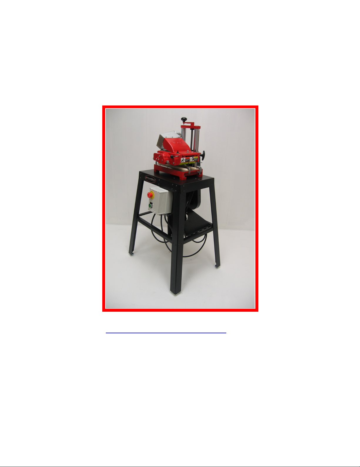
MODEL 154
OPERATOR’S MANUAL
MANUAL # OM-98
WILLIAMS & HUSSEY MACHINE CO., INC.
www.williamsnhussey.com
1-800-258-1380, fax 603-732-4048
Customer Service is available Monday-Friday, 8:30 AM- 4:30 PM EST
11th revision July 2010
Page 2

SPECIFICATIONS ACCESSORIES
MOTOR 2HP GUIDE SYSTEM GS-2
RPM 6900 ELLIPTICAL JIG EJ-92
FEED RATE 15 FPM RETRO KIT VF-104-K
MAX PROFILE DEPTH ¾” RETRO KIT VF-106-K
MAX PROFILE WIDTH 6 ¾” 11FPM KIT 54-310-K
PLANING WIDTH 7” 20FPM KIT 54-311-K
MIN STOCK LENGTH 9” R. PANEL KIT 54-312-K
MIN STOCK THICKNESS ¼” CRANK EXTEND 54-306
MAX STOCK THICKNESS 8” PINT OF G. B. OIL 54-416
WORKING HEIGHT 35”
OVERALL HEIGHT 50”
OVERALL WIDTH 22”
OVERALL LENGTH 28”
SHIPPING WEIGHT 218#
SAFETY RULES
Your 154 Molder has been designed for maximum safety. However, as with all power tools, there is a
possibility of incident or injury to the operator. Therefore, it is imperative that this manual is completely read
and understood before using.
Use your 154 Molder with respect and caution. Following stated and inherent safety precautions will
considerably lessen the possibility of personal injury. If normal safety measures are not taken or are overlooked,
the possibility of incident rises tremendously. These safety measures are simple to follow, and the injuries that
could happen are not worth the few minutes saved by ignoring safety.
The 154 Molder was designed for specific applications. Do not modify or use the machine for any purpose other
than what this manual describes as its capabilities. Substituting a motor with a horsepower rating over 2HP
constitutes a modification. Any modifications or improper use to the Molder-Planer may result in personal
injury, and will void the warranty. Please contact us if you are unsure about safety protocol before using the
machine.
SAFETY CHECK LIST
DON’T TAKE UNNECESSARY RISKS!
Failure to read and apply the manual instructions will cause poor performance, unnecessary repairs and
injury.
Wear safety glasses and respiratory protection.
2
Page 3

Disconnect the power before servicing or changing knives.
Wear footwear that does not slip. This will help you keep proper footing and balance.
Always stand beside the machine, never in the way of the in-feed or out-feed areas.
Keep the knives sharp and clean.
Make sure the machine has proper grounding.
Make sure all guards are secured and in working order.
Remove all adjusting keys and wrenches before starting.
Check the stock for loose knots, nails, and foreign matter.
Keep the machine in a dry, clean, well-lit area.
PREPARING TO USE THE MACHINE
1. Disconnect the power source while going through steps 1-10.
2. Check the oil level. The oil cup should be 1/3 full. This is important because a lack of oil will cause
many mechanical problems.
3. Check knives to ensure that the bolts are tight. If molding, set your guides for the stock path through the
knife area. If planing, you may or may not wish to set your guides. Many times,They are not needed in
planing. When planing unscrew all four pressure screws exposing ¼” of thread to have the correct roller
pressure. This setting is for planing only! Failure to do so will cause feeding diffuculties and feed system
damage.
4. When molding, the head scale setting must be set to within 3/16” of the height of your stock entering the
machine, compensating for any sub-plate thickness. This setting will provide the proper roller tension.
Any other setting further away from the thickness of the stock entering the machine is unacceptable and
dangerous. See the molding section for more information.
5. Attach the chip deflector with its pin. Make sure the pin is inserted all the way in until you feel it
“catch” on the spring-loaded catch. When detaching the chip deflector, take the pressure off of it by
lifting up off of its stop. This will allow for simple removal of the chip deflector.
6. With the power off roll the knife arbor by hand to ensure the knife area is clear.
7. Do not stand or let others stand in the out-feed area or directly in line with the in-feed of the machine.
8. With the head set in the proper position, tighten the head locking bolt firmly. This is essential for safety
and to ensure the machine head will stay where you have set it.
9. Set the head at the proper height for a test piece of stock and make sure the stock will make good
contact with the in-feed roller.
10. Check to make sure it is safe to start the machine, connect to power and test to see if the motor rotation
is correct before molding any stock.
3
Page 4

MOTOR LOCK
KNIFE
ARBOR
KNIFE BEVEL
INFEED SIDE
OUT-FEED SIDE
VIEW FROM PULLEY SIDE OF MACHINE
ROTATION
Your newly designed machine base has a motor lock. This new devise allows you to lock your motor in place to
keep it from bouncing on the belt during interrupted cuts etc. It also allows you to modify the belt tension which
can aid you in achieving the finish quality you are looking for.
To reduce tension you can crank the head down to within 1/4” of the actual setting you will use and lock your
motor. Then reset your head to the 1/4” lower running position and your tension will be reduced. You can vary
the 1/4” factor to achieve the tension you desire.
Always unlock the motor before resetting the machine head height
KNIFE CHANGING
DISCONNECT POWER BEFORE CHANGING KNIVES!
PLANER KNIVES
Remove the chip deflector by first lifting it up and then pulling out the pin. Clean off knives and machine arbor.
Set one knife at a time in place against the lip of the arbor. Place the “bevel” of the knife as shown in the
illustration below. Tighten the eight bolts securely using a 7/32” allen wrench. After tightening, double check to
see that the knives are snug against the lip.
We do not recommend shimming out planer knives.
MOLDING KNIVES
Clean off knives and machine arbor. Set one knife at a time in place with
the bevel edge positioned as shown in the illustration below. Push the
knife firmly down against the arbor lip and sideways against the bolts in
the direction of the tube side of the machine. Hold secure while tightening
the bolts.
GEAR BOX OIL
Check your oil level every day before starting machine, and if running continuously, check the oil every hour.
The oil cup should be one third full. The gear box holds 2 oz. of oil.
We recommend using our W&H Gear Box Oil. A substitute for our oil would be Mobil SHC 634, but W&H Oil
is the best option. Any problems caused by not using the proper oil will not be covered by the warranty.
Some minor oil leaking is normal. A serious leak in a new machine is almost always caused by overfilling the
gear box. This is not a serious problem though, as the gearbox will eventually purge the excess oil. In an older
machine, worn shaft bushings are normally the cause of significant leakage. Replacement of these is relatively
simple.
KNIFE SHARPENING
For fast and professional results with minimum edge loss, return your knives to the factory for resharpening.
Have your knives resharpened when you first notice some dullness. This gives optimal performance and
maximum life span out of the knives.
We re-sharpen knives every day at our plant. We take care to preserve the life of your knife by either face
grinding or profile grinding, whichever preserves the knife life the most.
4
Page 5

Both molding and planing knives have an edge angle of 57 degrees measured off the back
of the knife. Hook angle is 11 degrees
The use of dull knives will put a strain on the feed mechanism and will result in your
need of a repair. Any problems created due to the use of dull knives are not covered
under the warranty.
Face of knife →
HOW TO MOLD
1. A sub-plate made of knife millable material will be needed on any job where the knife is designed to
cut below the bottom of the stock. This type of knife will hit the base of the machine if a sub-plate is not
used. An example of this situation would be the molding of half or quarter rounds .
2. If the knife comes close to the base of the machine, such as the bottom knife of any crown or bed
moldings, a sub-plate should be used to prevent damage in case of accidental depression of the head,
which would plunge the knife into the base. Our optional GS-2 guide system has a sub-plate built into it,
a fixed guide, flex guide, and ratchet handles, all for a very reasonable price.
3. A basic set of guides has been shipped with your machine. Place a sample piece of stock on the bed and
roll the knife profile to contrast against the stock and align the stock to the position you want it to run.
Lower the head to grip the stock with the rollers and set your solid guide and then set your flex guide
with a little tension. You may fashion a sub plate yourself and clamp it to the machine base. When using
a sub-plate, always remember to add its thickness to the stock thickness when setting machine height.
You will need longer “C” clamps when using a sub plate. See the guide section for more info.
4. Stock height should be uniform in size and to within 1/32” of finished molding size.
5. Stock width should be uniform and not extend beyond knife edges. Saw ripping to width will not make
the stock uniform enough for smooth flow through the guides, and thus, will not result in a satisfactory
molding. We recommend that all stock be planed in both width and height to near finished molding size
before setting up to do the profile.
6. When tightening the knives, push them firmly against the lip and sideways against the bolts in the
direction of the tube side of the machine for an exact profile match up. Hold secure while tightening
bolts.
7. Set the head height to within 3/16”of your stock height measured off the bed of the machine. If using a
sub-plate you must compensate for it’s thickness off the bed in your head setting calculation. This will
give you proper roller tension on your molding stock. This is the correct way to mold. It is acceptable to
leave 3/16” of the cut for multiple passes. But for safety reasons leave no more than 3/16”. Failure to set
your head height within 3/16” of the stock height will create an extreme safety hazard in that possibly
not enough roller pressure will be applied, or that no roller pressure at all will be applied
Example, You want to take a first cut at 3/16” above the “full cut” setting. You have a ½” sub plate on
the machine bed and you are molding a ¾” piece of stock. You set the machine head at 1 7/16”, adding
½” + ¾” + 3/16” = 1 7/16”. After this first pass you may take three more passes at 1/16” each to get to
“full profile cut”, or two passes at 3/32” each, etc. A complete revolution of the elevation handle is equal
to 3/32” in knife height.
5
Page 6

8. On some extremely deep or wide cuts, some prior stock removal will be required before molding. You
may remove this stock using one of the rabbet knives found in our catalog, or you may use a dado blade
on a table saw.
9. Do not cut a wider stock area than the knife was designed to cut. This will cause excessive heat in the
knife, burn your stock and puts a harmful load on the feed system.
10. The roll pressure screws are set at maximum molding pressure from the factory. They are screwed into
the head as far as possible and the check nut is tightened.
11. When you use the machine for planing you will need to reduce the roller pressure. Loosen the pressure
screw lock nut and screw out each pressure screw ¼” and retighten the lock nut.
12. To change the molding knives, remove the chip deflector by lifting it up and pulling out the pin. Set one
knife at a time in place with the bevel edge toward the in-feed end of the machine. Firmly push the knife
down against the arbor lip and sideways against the bolts in the direction of the tube side of the machine.
Hold secure while tightening bolts
GUIDES
a. Guiding your stock
b. Your machine comes with a 14” flex guide, a 14” solid guide and (4) C clamps to guide your
stock. To set these guides, first attach your knives to the knife arbor in the position you have
chosen, often a place where you can get the most out of your roller surfaces. Panel knives would
go to the far right. Smaller knives to the post side half of the mounting area and larger knives to
the central positions.
c. Roll one knife down pointing to the machine bed and place a sample piece of stock you are going
to mold on the bed. Align the stock to the knife profile and carefully lower the machine head
until the roller puts pressure on your stock to hold it securely.
d. Attach your flex guide to the side of the profile that will cut the least deep into your stock. This
will give the longest possible life to your flex guide. Attach both C clamps putting about a 1/32”
amount of pressure on the flex part of the guide. This will keep you stock from wandering within
the glide path. Angle the bodies of the C clamps away from the stock path.
e. Attach your solid guide on the other side of the stock. Push it up firmly against the stock and
install and tighten both C clamps angling the body of the clamps away from the stock path.
f. Remove your set up piece of stock by raising the machine head, and pulling the stock out from
the bed.
g. Your knives will usually cut into one or both guides. This is normal and expected. The guides
are effective and last a long time after being cut into many times.
As you become more familiar with the machine and its use, you will want to make wooden guides to suit
specific jobs.
Mold your bevels or bottom knife cut first when molding bed or crown
moldings. If ordering a custom bottom bevel knife you can have a key path cut
as a guiding mechanism for your top profile. Angled bottom cuts in crowns or
bed moldings require special attention. You must make a sample of the bevel
and top profile to see if everything is set to give you the result you desire. Once
a good sample is made use it to set up on in the future.
6
Page 7
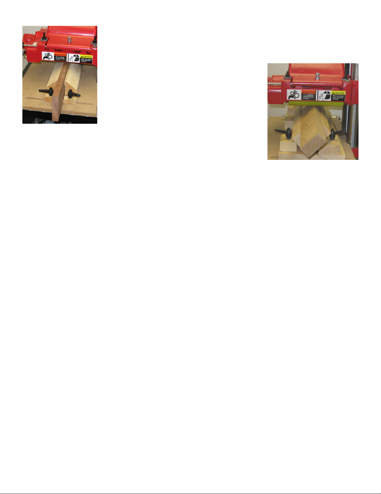
When planing the edge of stock, a high, square, relieved guide is needed in order to
have the edge reasonably square and to provide
stability. Use center reliefs to reduce friction.
Some profiles are too deep to make on the W&H. In
some cases you can rotate the profile into a flatter
position to effectively reduce the depth of cut.
A “vee block” guide would be made to guide your
stock. The profile knives would have to be custom
made to use in this vee block position.
When making tongue and groove stock, a serious and detailed approach is
needed in order to achieve a uniform fit. Carefully pre-inspect your stock for
cupping and warping. You need to plane all your stock to one uniform size.
The guide thickness should be 3/8” thinner than your stock or your roller will scuff on the guides when the
stock has left the machine and the rollers are in their rest positions. When running thin stock you will need to
fasten a sub-plate between the guides to maintain a thick enough guide to control your stock.
Always check your knife clearance to the guide. Clear away any interfering portion of the guide by gently
lowering your knife down into the guides to just below your running position.
MOLDING PICTURE FRAMES
Decide whether the rabbet or profile cut should be done first. If you are going to make the rabbet on the W&H
Molder, do the rabbet first. In order to utilize the W&H Molder for rabbets, a rabbet knife with a depth of cut
equivalent to the depth you need should be ordered. If we do not have a standard knife with the depth you seek,
we can make a special knife to suit your needs.
ROUND TOP CASINGS OR CONSTANT RADIUS SIZE ARCS
We manufacture knives with the profile cutting the deepest portion of the cut on the open side of the machine.
Notify us when you order a knife if you want the deep side of the cut on the vertical tube side of the machine.
The set up and operation of the W&H machine for a round top molding job is very similar to the straight
molding set up. The main difference is the stock is attached to a template that raises the stock up for the knife to
clear the jig hardware. Our EJ92 Elliptical Jig is not needed for a fixed, constant radius.
Stock preparation can be done in many ways. The following is one example.
First determine the angle needed to cut the wood sections in order to stay within the selected radius. Lay out the
wood sections by marking the angles while being careful to select cuts for grain structure and color. Cut the
sections and biscuit join them together with glue.
We made a fixture to band saw the inside and outside radii consisting of a pivot bar and bracket. We mounted
the pivot bar to the stock on the scrap portion of the inside radius. The pivot bar is drilled with numerous holes
to accommodate any radius sizes. You may also want to design a fine adjuster to allow you to make any radius
in between your adjusting holes. Make sure the outside radius is cut first.
7
Page 8
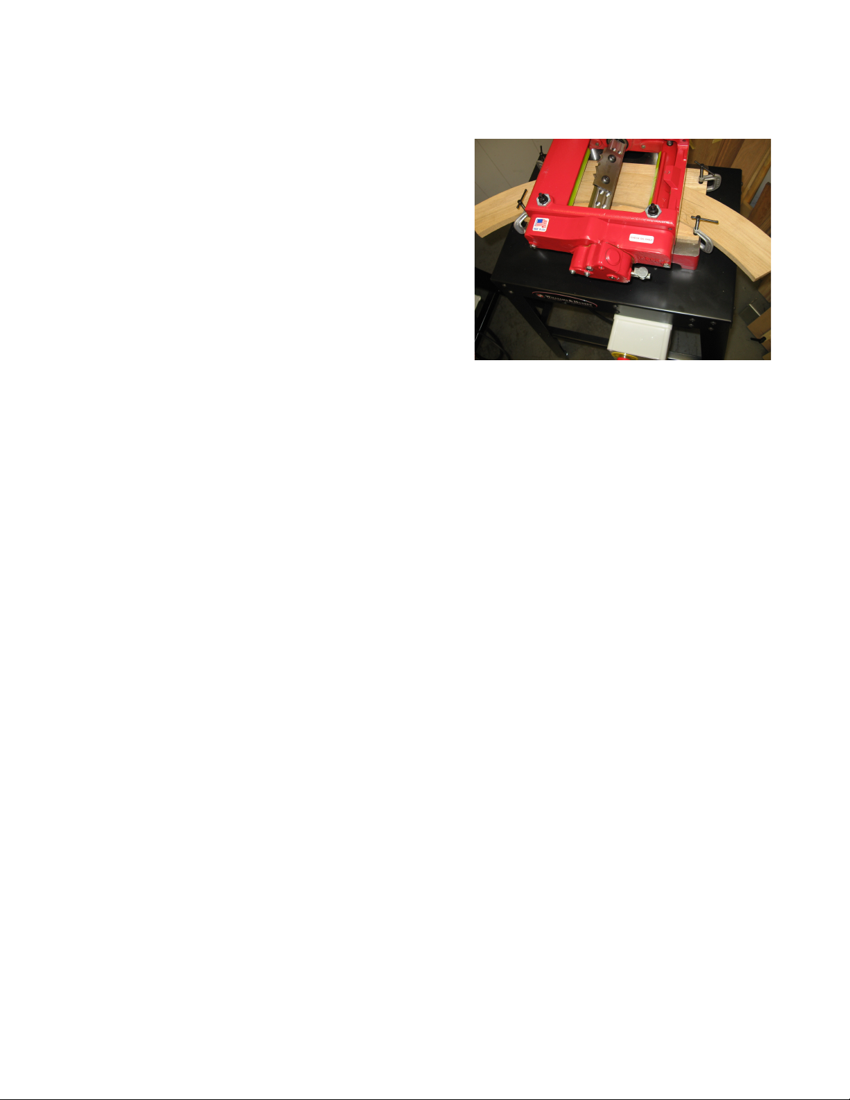
The guides should be 14” long if you are just using the bed of the machine and 20” long if you are using the
GS-2 guide system. The guides may be made using the band saw set up. We make one guide for the inside
radius and one for the outside radius. We use MDF board.
ROUND TOP SETUP
1. Make sure power supply is disconnected
2. Raise the machine head and set the stock on the bed.
3. Align the stock with molding profile.
4. Lower the head to pinch the stock.
5. Set the guides and clamp them in place.
6. Raise the machine head, remove the stock, and reset
the head to within 3/16” of stock size (Don’t forget
the sub-plate height if one is used).Ensure that there is
no interference in the knife area.
NEVER attempt closed loop molding. It is an unsafe
procedure.
RAISED PANELS
All of our panel knives are designed to produce a ¼” tongue. Be sure to select a panel knife based on the
finished panel thickness. A panel must be 9” or more in the direction you are molding in order to not have
the panel come off of one roller before it engages the second roller. When you use multiple passes you must
have at least 9” of panel remaining in the direction of the cut in order to have a least one roller on the panel at
all times.
If you desire a different tongue size or have a panel thickness other than ¾” or 5/8,” a special knife can be
ordered and shipped quickly by W&H.
THE SET UP
1. Disconnect the power supply.
2. Install your knives over toward the tube side of the machine allowing enough room to install your guide.
3. Index the knife arbor so the profile will be seen against the bed. Raise the head to allow the panel to be
laid on the bed and to be lined up with the profile visually.
4. Once you have found the proper position for the panel, lower the head so the rollers will put pressure on
the panel while butting the guide against the panel. Tighten your guide.
5. Raise the head, pull the panel out of the machine, and lower the head to within 3/16”of the panel height.
Rotate the blade arbor by hand to insure nothing is interfering with its rotational path.
6. Mold the panel cross grain ends first. Stand somewhere between the open side and in feed side. See the
picture on the next page.
RAISED PANEL ISSUES
It takes some practice to make a good panel. It is helpful to keep a slight upward pressure on the panel as it is
being molded with a steady pressure against the guide.
Because panels are normally larger than the 7” cutting capacity of the machine, the panel must pass beneath the
open side of the head. There is approximately 1/32” clearance between the top of the panel and the head of the
machine, provided the head is at stock size setting, and not below.
Many users try to create a slightly deeper cut to modify the tongue size or change the profile appearance and
end up dragging and pivoting the panel away from the guide path. The head must be set at the panel thickness
and not below it in order to have clearance to pass the panel through the machine in a satisfactory way.
8
Page 9

On occasion you may find a light chain imprint on the top of your panel. This mark may be removed when you
are finished molding your panel with a thickness planer or sander. Or, you may install a W&H Raised Panel Kit
that will eliminate the chain mark entirely.
HOW TO PLANE
CAUTION! When you use the machine as a planer you will need to back off all four pressure screws ¼” so
that you will not have too much roller tension, or you will risk shearing a pin in the large bronze worm gear.
Measure the thickness of your stock.
The amount of stock that is removable in one pass is dependent on the density of the wood (relative hardness),
how wide the cut is, and the moisture content of the stock.
GENERAL GUIDELINES FOR DEPTH OF CUT
THICKNESS TYPE OF WOOD DEPTH OF
CUT
1” Poplar ¼”
1” Red Oak 3/16”
3” White Pine 3/16”
3” White Oak 1/8”
6” Poplar 1/8”
6” Red Oak 1/16”
See the table of contents section for knife changing and installation.
Loosen the planing head locking handle (54-21). To initially begin planing, set the head position to a height
1/32” less than the dimension of the stock entering the machine. One-third of a turn on the elevating handle will
equal 1/32”. Tighten the head locking knob.
Make sure the chip deflector is in place and the pin is firmly seated.
Check to see that the chip deflector height is adjusted so that the bottom of the deflector does NOT ride on the
stock. Contact between the deflector and stock has the potential to damage either the stock or the machine and
cause undesirable results.
Utilize a high, square, relieved guide when planing the edge of stock to ensure the edge will be reasonably
square. A relief in the vertical wall of the guide reduces friction.
9
Page 10

CHATTER
Definition
Chatter marks are irregularities in the finish
quality of the surface of the wood. They can be
evenly spaced or randomly distributed. Simply
put, they may be described as “hills and valleys”
in the wood surface.
Cause
These marks are caused by either loosely held
stock or by an imbalance in the machine’s
mechanical qualities
Solutions
The most common cause of poor
stock finish quality is a rough running
belt. Replace the belt.
Make sure you are cutting with the
head set at the appropriate height.
Keep your knives sharp. Dull knives
cause intermittent feeding.
Check the pulleys for damage or
imbalance.
Check to see that both knives and all
attaching bolts are of the same
weight.
SNIPE
Definition
Snipe is generally an unwanted undercut in the stock. It occurs in the
first and last few inches of the stock length. It causes a different
height dimension than what was selected for the stock.
Causes
The stock may be cupped, warped or twisted.
The stock experiences a change in down pressure as the out feed
roller engages the stock, and when the stock disengages with the in
feed roller.
The stock may enter or exit the machine on an angle because it is
either being fed from a higher or lower plane than the bed, or it is
exiting to a higher or lower plane.
Solutions
Use a jointer to flatten cupped, warped,
or twisted stock.
Butt stock pieces tight end to end.
Put a slight upward pressure on the
exposed end of the stock during both the
in feed and out feed stroke.
Use slightly longer stock length than
needed and cut the snipe off.
Make sure the head locking handle is
tight.
Your outboard support should be
slightly higher than your bed.
10
Page 11

FEEDING PROBLEMS
Make sure that power is disconnected before inspecting machine!
SYMPTOM SOLUTION
The stock stops but the feed-rollers
continue to turn.
This is a traction or friction problem.
1) Make sure your stock is not binding
in the guides.
2) Make sure the stock is of consistent
width. Saw ripping is inadequate.
3) Make sure stock is the proper width
for the knife profile.
4) Make sure the head is set at the
correct height.
5) Check the rollers for wear or pitch.
6) Check your pressure screw pressure.
7) Check the base or bed for rust or
scars.
One roller stops while the other
continues to operate.
Both feed rollers turn until you try to
engage stock and then both stop.
Neither feed roller will turn even in the
absence of stock.
Check for a loose set screw on one of the
two chain sprockets involved with the
roller that won’t operate.
Check for a broken roll pin in the P-108
bronze gear, P-504 assembly. Check the
pin with a paper clip wire. If the wire will
not go in one end of the pin and out the
other, the pin is broken. The pin is a 1/8”
diameter spring tension roll pin 5/8”
long.
1. Check for a broken fiber drive, P117.
2. Check for a broken primary shaft,
P203.
3. Check for a stripped small bronze
worm gear, P105, inside the gear box.
THREAD LOCKING INFORMATION
A medium strength thread-locking compound used on some parts prone to loosen with vibration.
Use two drops on the thread area of the parts listed below.
P-122 Post side axle, 54-16 Rest pins, 54-15 Pivot screws.
A tube of thread locker is available for purchase. Part number P-242.
Do not use on P124 in-feed axle, or on P224, out-feed axle.
11
Page 12
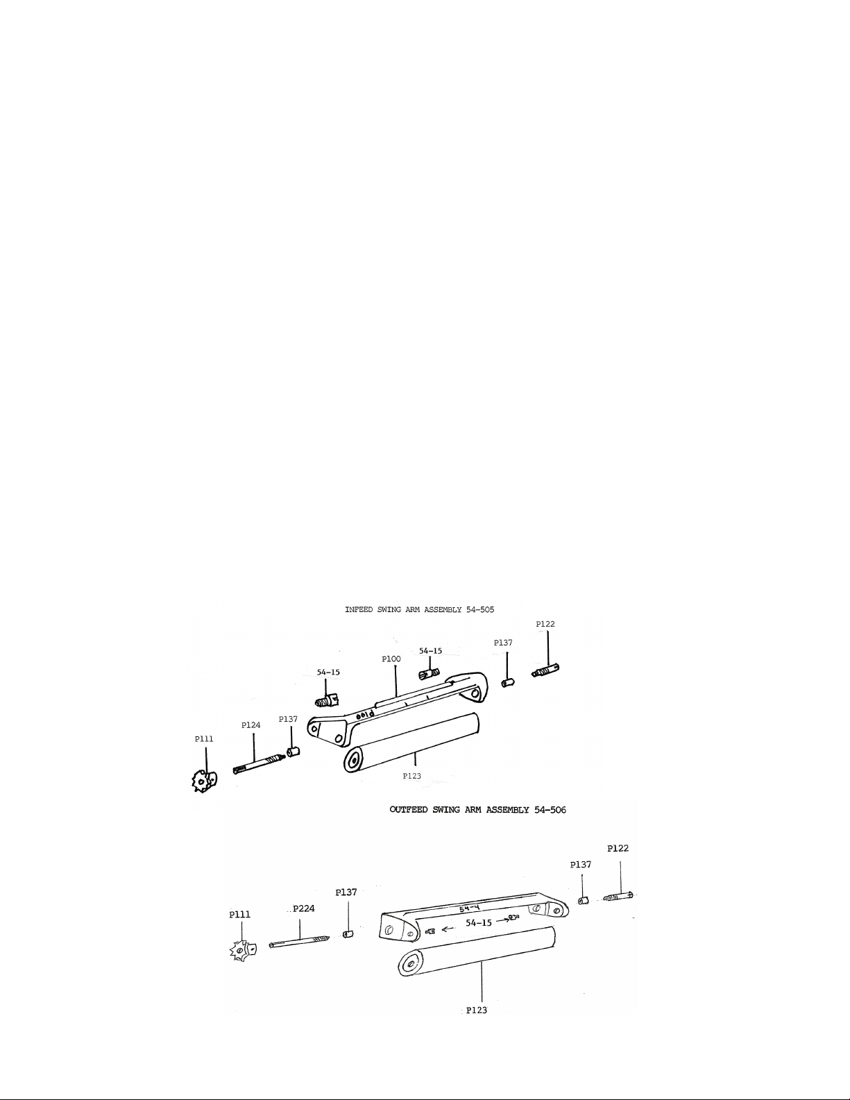
INSTRUCTIONS FOR REMOVAL OF FEED ROLLER
Unplug machine.
Take off chip deflector.
Raise head.
Remove pressure screws over swing arm to be removed.
Remove two 54-15 pivot screws and remove swing arm, leaving chain connected to mating sprocket.
Reinstall each pivot screw with a drop of medium strength thread locker.
Take P-111 sprocket off swing arm axle. Put the feed roller in a vise. Use a couple of small adjustable
wrenches attached to the flat on the long axle to loosen it. Machines with an optional feed kit may have
sprockets that have a different number of teeth and different part numbers.
Put a good square shank flat bladed screw driver into the slot on the short axle. Push in as hard as you can
while using a wrench on the square shank of the screw driver to loosen the short axle. Sometimes this axle
will not come out. Hack saw it off if it won’t. If you need to save the roller, pull the roller out of the swing
arm by lifting it up and pulling it out with the short axle still in the roller. Reset the roller in a vise and use a
small pipe wrench to remove it from the roller.
REASSEMBLY
The rollers are constructed with a shallow hole in one end and a deeper hole in the other.
The P-122 always goes in the short end. Reinstall the P-122 parts with two drops of medium strength thread
locker on the thread portion. If you don’t they will back up and jam your gear box.
The longer axle goes in the deeper end. See drawing for swing arm assembly with roller. Do not use thread
locker on this longer axle.
12
Page 13

REMOVAL OF POWER FEED UNIT
1) Disconnect power. Remove chip deflector and raise head 4”-5”.
2) Spin the arbor to find the set screw on the in-feed chain sprocket on the underside of the chain guard.
Using a 3/32” allen wrench, loosen the set screw.
3) Starting with the bolts on the chain guard, remove the three hex head bolts attaching the power unit to the
head.
4) Pull power unit free, removing the in-feed sprocket and chain at the same time. Remove the long chain
once the unit is partially free of the head.
DISASSEMBLY OF THE GEAR BOX
1) Loosen set screws on the P110 gear box mounted sprockets and pull them off the P209 drive shaft.
2) Remove P213 nylon bushing and P214 nylon washer.
3) Drain the oil.
4) Remove four socket head cap screws holding gear box onto the chain guard.
5) Tap on the two shafts with a soft hammer to separate the two housings.
6) Drive out P-504 large bronze gear assembly from outside of the gear box with a ¼” pin punch. Watch for
small spacer P-127.
7) Drive out 1/8” dowel pin P-143 joining upper P-115 bearing support plug to gear box. Push out the plug
with a screw driver from the inside of the gear box.
8) Remove P-503 secondary shaft assembly (small bronze gear). Wiggle it out of its socket and remove it
from the gear box through the open side of the gear box.
9) Remove the P-502 primary shaft assembly (small worm and slotted end shaft).
INSTALLATION OF POWER FEED UNIT
1) Disconnect the power source to the machine. Remove any knives and bolts from the machine
arbor. Please note that the gear box/chain guard assembly shall be referred to in these instructions as the
power feed unit.
2) The P-117 fiber drive should be in the end of the arbor. The out feed roller sprocket should be on
its shaft. Both swing arms are installed and all four pressure screw assemblies should be in place.
3) The power feed unit should be fully assembled with the P-213 nylon bushing on the P-203
primary shaft (shaft with slot) and the P-214 nylon washer up against the P-213. Both P-110 gear box
mounted chain sprockets (sprockets with thin hubs) should be on the P-209 drive shaft, with the thin hubs
facing toward the chain guard. Leave a 1/32” gap between the innermost P-110 and the chain guard P202 (longer feed unit casting). Tighten the set screws in each of the sprockets onto the flat on the P-209
drive shaft.
4) Install the long chain on the driving sprocket closest to the P-202 chain guard. Droop the chain
over and under and the nylon bushing P-213, and against the nylon washer P-214.
5) Install the short chain over the outermost P-110 gearbox mounted sprocket. Engage the roller
sprocket (which is not on its shaft yet), in the short chain with the hub facing the machine head and the
set screw facing down for access later to tighten it.
6) With the attaching bolts nearby, pick up the power feed unit and first engage the long chain on
its roller sprocket. Next, engage the in feed roller sprocket on its shaft and at the same time insert the
13
Page 14
primary shaft P-203 into the end of the arbor with the slot straddling the P-117 fiber drive. Install the
three attaching bolts, tightening only the longest bolt.
7) Tighten the in feed roller sprocket set screw on its shaft flat with the chain in a straight line
position with its mating sprocket.
8) Check the oil level now in the gear box and fill as needed. It holds 2 oz. Fill to 1/3 full on the oil
cup.
9) Install the chip deflector. Check to see that all belt guards are in place. Make sure all is clear
inside the arbor area and around the machine.
10) Start the machine with the attaching bolt wrench ready to loosen the center bolt to make the final
smooth running position check of the power feed unit. Move the unit around within the limits of the
attaching bolt hole clearance and find the quietist running position. This will be when the primary shaft is
most centrally located in the end of the arbor. When this position is found, tighten all three attaching
bolts, starting with the central one.
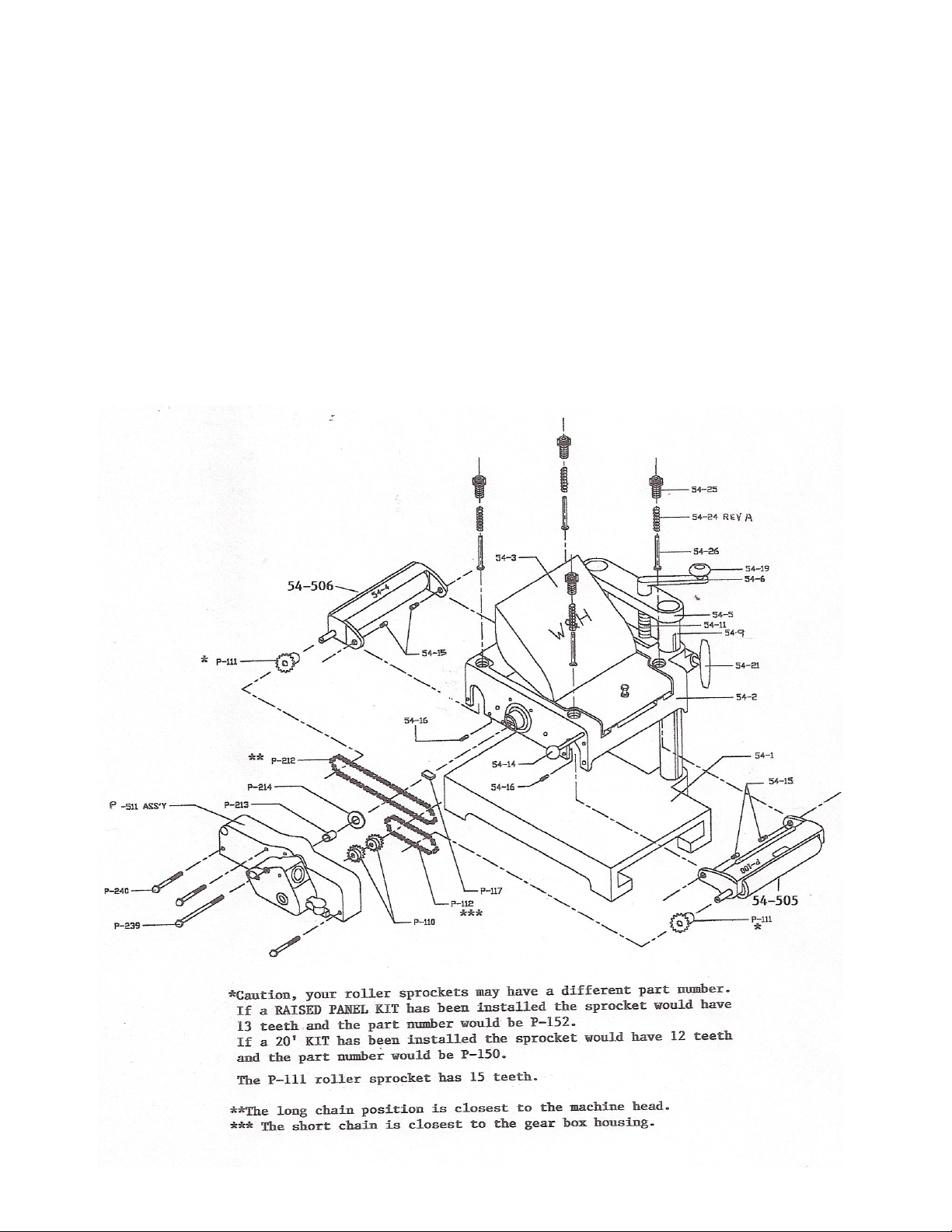
MACHINE PARTS ILLUSTRATION
14
Page 15
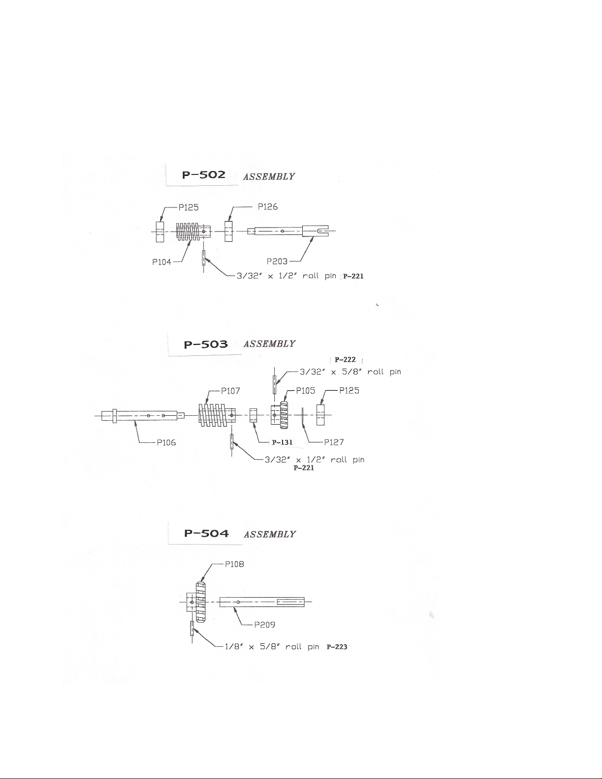
GEAR BOX SHAFT ASSEMBLIES
15
Page 16
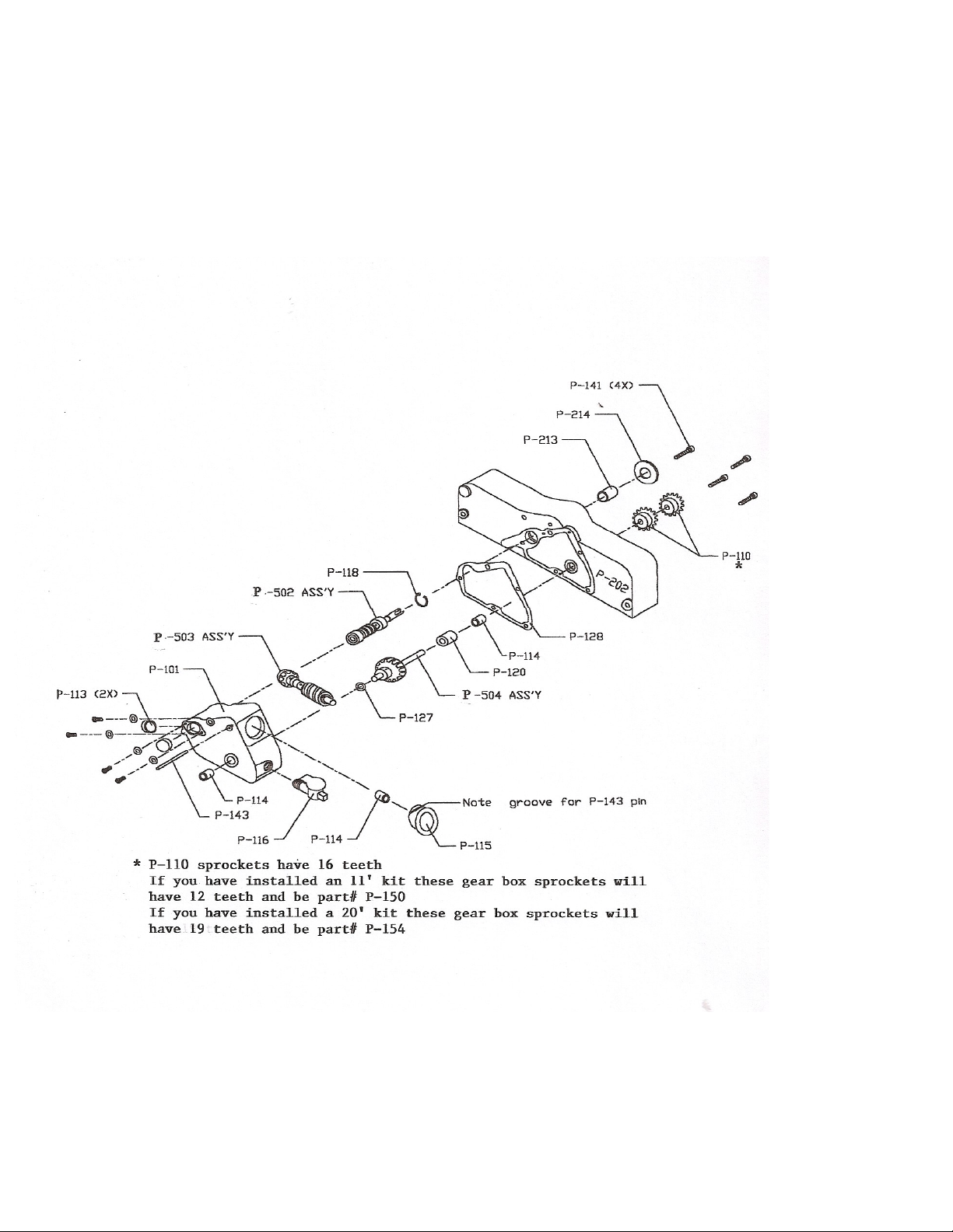
GEAR BOX ASSEMBLY VIEW
16
Page 17
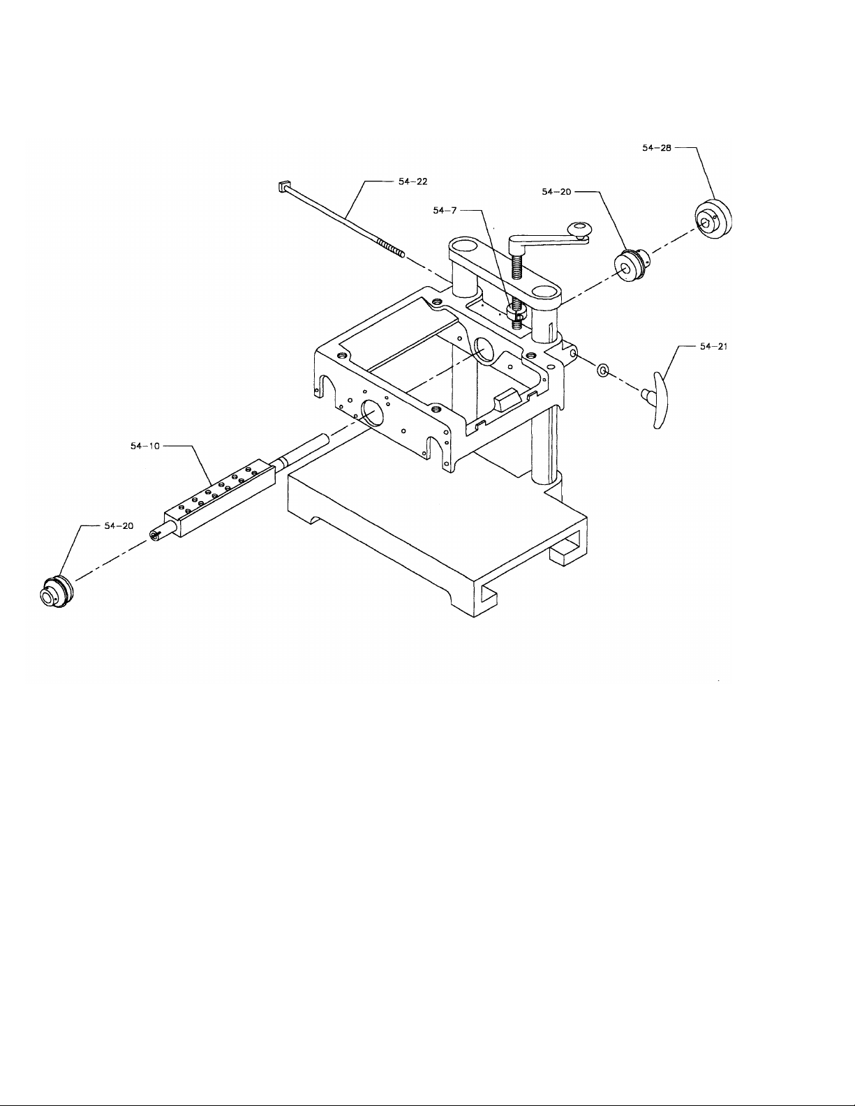
ARBOR REMOVAL VIEW
17
Page 18

CONTACT INFORMATION
Williams & Hussey Machine Co., Inc. [email protected] (e-mail)
70 Powers Street
Milford NH 03055 williamsnhussey.com (website)
603-732-0219 (local) Business Hours: Monday – Friday
800-258-1380 (toll free) 8:30 am – 4:30 pm
603-732-4048 (fax)
WARRANTY INFORMATION
Molder – 7 Year Limited
Williams & Hussey Machine Co., Inc. warrants its molders for a period of seven years from the original date of
purchase.
WHAT IS COVERED?
The warranty covers any defects in workmanship or materials.
WHAT IS NOT COVERED?
The warranty does not cover damage due to; modifications, misuse, improper maintenance, normal wear, wood
jams or using a knife motor with a horse power rating over 2HP.
WHO IS COVERED?
The warranty covers the initial purchaser only.
LIMITATIONS ON WARRANTY
Williams & Hussey shall in no event be liable for death, injuries to persons or property, or for incidental,
contingent, special, or consequential damages arising from the use of our products.
Motors - 2 year Limited
Warranty covers any defects in workmanship or materials on original parts. Warranty does not cover defects
due directly or indirectly to misuse, abuse, negligence or accidents, normal wear-and-tear, lack of maintenance,
or improper repair or alteration.
Controls & Elliptical Jig - 1 year Limited
Same as motors.
VF-104 and VF-106
Refer to applicable motor and control warranties.
AUTHORIZATION FROM WILLIAMS & HUSSEY IS REQUIRED
BEFORE ITEMS ARE BETURNED FOR EVALUATION.
18
 Loading...