

Wfly X4 Instruction Manual

ORIGINAL 2.4GHz
2.4GHz
X4
Instruction Manual
Shen Zhen WFLY Tech nology Development Co.,Ltd.
www.w flysz.c om


Before using ,
please make sure you must understand the following information.
When O pening th e package , please co nfirm the f ollowin g items are c omplete .
Matc h the differe nt parts of the assembly the articl e is also diffe rent, ple ase
conf irm it acco rding to th e followi ng chart.
If mix ed with the c ounterf eit produ ct which re sult in dam age, the co mpany
shal l not be resp onsible f or it
Plea se use this b ook or cata logue whi ch have rec orded the p roducts .
●
●Receiver (WFR04H)
●Battery box for the transmitter
●Instruction book
●Foam box
●Color box
Transmitter (X4)
If the re is insuffi cient or un clear poi nt for the pack aging con tent,
plea se refer to t he model sh op for more i nformat ion.
Packed content
3
x1
x1
x1
x1
x1
x1

4
5
Logo M eaning
Atte ntion Poi nt For The Us ing Of 2.4G Hz System
Atte ntion Poi nt For The Us ing Of High S peed Mode
Atte ntion Poi nt For The Dr iving
Atte ntion Poi nt For The Ba ttery
Atte ntion Poi nt For The Sa ved And Wasted Bat tery.
Othe r Matters N eeding Attentio n
Attention Point For The Mode Setting Of Steering Response
The Using Method Of The Transmitter
The Na me Of Each Pa rt Of The Transmit ter
The Powe r Switch And R f Switch
Low Vol tage War ning
The Oper ation Mod e Of Digital Trimming
Grip L ever Oper ation
The Adjus tment Met hod Of Mechanical Range
Adjus tment Met hod Of Whee l / Trigger Tig htness
Adjus tment Met hod Of The Trigger Position
Meth od For Repl acing The Lef t And Right Hand
Using Method Of Transmitter Antenna And Receiver
Ante nna Relat ed Matter s
The Name O f Each Part Of The Re ceiver
Rece iver Code M ethod
The Rece iver Indi cator Lam p Status Confirmatio n
The Inst allatio n Method Of Receiver
Assembling Method
Safe ty Consid eration s When Assem bled
Initial Set-up
The Pr eparati on Before The Tr ansmitter Sets
Switch, Button Description
The General Mode Of Operation
Description Of Indicator Lamps
Rece iver And Ser vo Connec tions
20
23
26
20
20
21
21
22
23
24
26
28
28
28
Terms Of Use
Important Notes
9
13
9
9
9
10
11
12
12
13
14
14
15
15
15
16
16
16
16
17
Contents
Direction [STEER]
Expo nential C urve [EXP ]
Dire ction Del ay [SPEED ]
Throttle [THR]
Expo nential C urve [EXP ]
Thrott le Delay [S PEED]
Accel erator [T H ACC]
Primary Setting
Posi tive And Neg ative Set ting [REV ]
Digi tal Trimmi ng [TRIM]
Auxil iary Tunin g [SUBTR]
Trave l Set [EPA]
Lose C ontrol Of P rotecti on [F/S]
Posi tion [POS ]
TIME R
Circ le The Number L ist [LAPL IST]
The Si ze Of The Action [ D/R]
Can St ore 40 Sets O f Model Dat a
Spec ial Brake M ixing For L arge Car (B RAKE)
Anti L ock Braki ng System ( A.B.S)
Acce lerator ( TH-ACC)
Stee ring Spee d (ST SPEED)
Thro ttle Spee d (TH SPEED )
Tim er (TIMER )
Fine / The Selec tion Of Swi tch Funct ion
Product Features
Function Chart
Function Description
Main P age
Dire ctory Str ucture
The Fu nction Table
29
30
33
29
29
29
29
29
29
29
29
30
30
32
33
33
34
35
36
37
38
38
38
39
39
40
40
41
33
35
38
6
Contents

Contents
Advanced Function
Prog ramming O f Mixed Con trol
A.B.S
Brak e Mixing
Four W heel Stee ring
Fron t And Behind The M iscible Flooding
Thrott le Mode
Function Selection [DIAL SW]
Swit ch, Butto n
Fine Tu ning Opti ons
Specifications
Tra nsmitte r
Rece iver
Function Description
Reference
53
52
52
52
52
53
53
53
53
42
42
43
44
45
46
47
49
51
51
51
51
51
42
54
7
Model Information
Mode l Selecti on
Mode l Replica tion
Mode l Name
Fact ory Setti ng
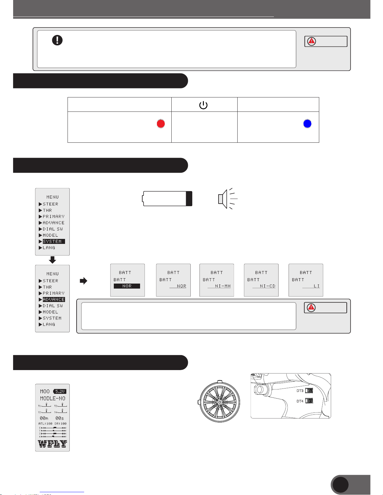
System Settings
Back light Lam p
The To ne
Powe r Supply Sc heme
Versi on Inform ation
High S peed Mode
Code
Language
Adjus tment
49
50

8

Important Notes
In order to ensure the safety of yourself and others, when using this product,
please pay attention to the following matters.
Logo Meaning
The following logo appears in the book, indicate the safety consideration,
please pay special attention to.
Prohibited items
Be sure to keep matters
Circular logo:
The Attention Use Of 2.4GHz System
Inte rferenc e effects may be subject to ot her 2.4GH z systems l eads to sig nal canno t be
deli very. If such th ings appe ar before the using of act ion test or u sing it ple ase stop
usin g.
In vie w of the safe ty Please s et out the lo se contro l of protec tion func tion.
Note : The Use Of High Speed Mode
When u sing the hi gh speed mo de, pleas e use the dig ital serv os.
When u sing the no rmal mode , please us e the analo g actuato r.
Igno rance of th is logo and t he operat ion error, m ay lead to th e
user o r others to d eath and in jury risk .
Igno rance of th is logo and t he operat ion error, m ay lead to th e user
or oth ers to deat h and serio us injury r isk, or mad e A min or injury o r
poss ibility d amage of th e gods.
Igno rance of th is identi ty and oper ational e rrors, th e possibi lity of
maki ng users or o thers inj ured is not h igh, ther e are still m ay
inju red or caus e damage to t he gods .
9
Danger
Warning
Careful

Items Needing Attention While Driving
Driv ing is forb idden dur ing the Rai ny day, strong wind and night the transm itter can not opera te
,con trol or los t its way aft er droppi ng it into th e water .
No dri ving in the f ollowin g places.
•N ear the cro wded peop le .
•N ear the hig h voltage e lectric ity or comm unicati on statio n.
•W henever t he interf erence of w aves, obs tacles or t ransmit ter, or the ve hicle fault cause body
out of c ontrol , it may cause other people death .
Do not d rive when y ou are tire d, ailing o r drunken , unable to c orrectl y judge the e asy opera tion
erro r, tend to dan ger.
Befo re drivin g you must te st launch r eceivin g system an d dynamic m odel, con dition of the
cont rol funct ion.
Rega rdless of t he remote c ontrol or a ny part of th e model abn ormal may c ause out of c ontrol.
A sim ple test me thod:
Plea se hold the m odel car by t he helper o r fixed on th e platfor m, try to ope rate all th e site ,
conf irm wheth er action a nd comman d is consis tent. If yo u can't con trol or the abnormal
move ment.
Usin g it or after u sing do not i mmediat ely touch t he engine , motor and e lectron ic transmission
devi ce. The high te mperatu re may caus e burns.
When t he power is o n:
Thro ttle trig ger trans mitter ma intaine d at the stop p osition .
1, tur n on the tran smitter p ower firs t
2, the n turn on the r eceiver p ower
The op posite op eration , may cause t he body out o f control , and risk.
When t he power su pply is swi tched off :
Afte r stoppin g the engin e or motor
1, tur n off the recei ver power
2, and t hen turn off th e transmi tter power
The op posite op eration , may cause t he body sho rt burst, d anger!
Plea se stop the e ngine ope ration be fore the ad justmen t of remote c ontrol (p ower off).
If you d on't stop t he engine o peratio n in advanc e the body bu rst dange r may occur .
10
Warning
Important Notes
Careful

Plea se check th e functio n of losing c ontrol pr otectio n is normal b efore dri ving
Conf irmatio n method:
1, Ope n the trans mitter fi rst and the n open the re ceiver po wer;
2, set t he lose con trol of pro tection f unction c onnect to t he receiv er (39 page s);
3, tur n off the trans mitter;
4, con firm the fu nction un der the los e control p rotecti on the thro ttle and ch annel can o perate in
a sett ing posit ion.
Lose c ontrol of p rotecti on functi on is when th e receive r can not rec eive the si gnal, Let the
actu ator set th e positio n move in adv ance Make t he hurt to th e lowest sa fety auxiliary funct ion
But if t he positi on set in adv ance is dan gerous po sition, i t will caus e the posit e effe ct.
Case : the throt tle setti ng is safe in t he midpoi nt positi on.
Attention Point For The Battery
Do not u se wet hand . To Plug t he charge r to avoid th e risk of electric shock .
Befo re drivin g, make sur e the trans mitter fo r battery c harging .
Driv ing power i s insuffici ent, ther e will be danger burst.
When t he Nickel c admium ba ttery of th e transmi tter is cha rging, pl ease be sur e to use the
dedi cated cha rger.
Char ging exce eds the spe cified va lue will be t end to abno rmal heat ing, rupt ure, batt ery fluid
leak age .Inju ry, fire damag e, blindn ess may happen .
Avoid ni ckel cadm ium batte ry link end m ay result in short circu ited.
If the s hort circ uit will be o n fire, abn ormal hea t, will cau se burns or f ire.
Ni/MH Ni/Cd
Using NiCd/NiMH battery
11
Careful
Careful
Warning
Important Notes
Avoi d nickel-cadmium batteries fall ing from a high place ca use strongly hit.
Strongly hit the battery may cause t he battery short circuit, abnorma l heat, damaged
battery fluid leakage Cause burn s or chemical damage .
Be sure to the battery should discon nected. when the exe rcise is no longer operate
Do not plug in the socket.when the cha rger is not charging
Avoi d abnormal heating accident.
Preservation And Waste Batteries Considerations
Chil dren may to uch the tra nsmitte rs or body wh ich cause t he injure o f the body , or playing the
batt ery causi ng chemic al Substa nce intox ication .
Can no t put the nic kel-cad mium batt eries int o fire or hea t, nor make i ts decomp osition o r
tran sformat ion.
If the b attery ru pture, ab normal he at or leaka ge of batte ry fluid ma y cause bur ns or blindness.
<Nic kel-cad mium, nic kel-met al hydrid e battery e lectrol yte>
Cont aining hi ghly alka line batt ery, if they fall into the eyes i t can cause b lindnes s. If flow in to the
eyes b y acciden t you shoul d immedia tely wash w ith the cle an water be fore seei ng the doct or . In
addi tion, the e lectrol yte will da mage the sk in, if the sk in or cloth ing is Dip in to the elec trolyte , you
shou ld immedi ately was h with clea n water. (Ex cept lith ium)
The re mote cont rol can not b e stored in t he follow ing locat ions.
• extr emely hot p laces (ab ove) - a very c old place ( - less)
• dire ct sunlig ht and high h umidity p laces pla ces •du sty places
• vibr ation pla ce more ste am spaces
If sto red in the ab ove areas , it will lik ely to caus e deforma tion or fai lure.
Other Considerations
Do not l et the plas tic parts d irectly c ontact to t he fuel, oi l, exhaus t, etc.
if the P lastic pa rt expose d to fuel and o ther subs tances ma y be corros ion which w ill cause the
dama ge.
Tra nsmitte r, receive r, servos, e lectron ic transm ission, n ickel-c admium ba tteries a nd other
devi ces must ma tch the sta ndard pro duct to use .
12
Important Notes
Warning
Careful

If you want to use t he X4 high speed steer ing response mode, y ou must
meet the following conditions:
With the 6V 270Hz specifications : digital servos.
The 6A nickel cadmium battery the usi ng power for the recei ver .
The transmitter steering respo nse mode setting: hi gh speed mode
(refer to page 53).
When using the s imulated steerin g, be sure to transform the response
mode of X4 steering into the normal mo de .
The use of X4 common steering respon se mode, must meet the f ollowing
conditions:
With the 6V 50Hz specifications: S imulation of steer ing gear.
The use of nickel cadmium battery po wer receiver: 6V.
The transmitter steering respo nse modes: normal mo de
(refer to page 53).
Simulation o f steering gear can no t normally oper ate in the highspeed mode ,
And also can con nect to the steering o f the receiver and other part may
happen failu re .
In normal mode , digital servos als o can normally op erate ..
13
Warning
Attention For The Mode Setting Of Steering Response
Terms Of Use
SW2
0
1
2
The Using Method Of Transmitter
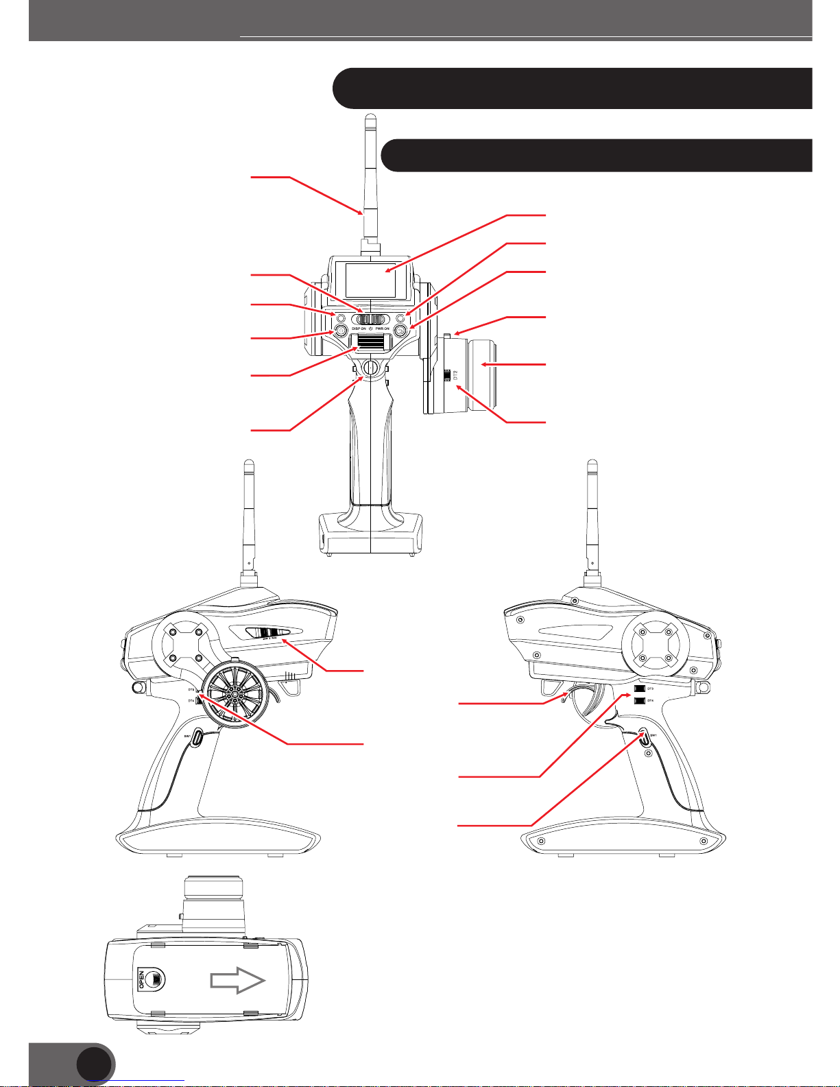
The Name Of Each Part Of The Transmitter
DT2
DT3、 4DT
Butt on (SW.1)
The tr igger
Slid e switch (S W.2)
A bri ef descri ption of th e battery i nstalla tion
1, as sh own in the pi cture to op en the batt ery compa rtment co ver.
2, the b attery re moved.
3, rep lace the ne w battery. (pa y attention to the polar ity of the
batt ery, can not be re versed)
4, the b attery co mpartme nt cover sh ould put ba ck into the o rginal
plac e
14
Ante nna
Disp lay
Retu rn key
DT1
Stee ring whee l
The po wer switc h
Menu k ey
Roll er and defi ne key
Debu gging ind icator
Stat us indica tor
Ring s
DT2
Terms Of Use
15
When y ou Close th e battery c over,
plea se don't le t the lid nip t he connec ted line of b attery.
If the c able is cla mped whic h cause a sho rt circui t,
will b e outbrea k of fire, ab normal he at, cause b urns or fir e.
The Power Switch And RF Switch
Low Voltage Warning
When t he batter y and volta ge of the tra nsmitte r is lower th an the usab le range th e
warn ing sound , and the two i ndicato r lights.
Lith ium ion bat teries, n ickel met al hydrid e, nickel c admium, s tem cells c an use the
differ ent volta ge range , so i t must be in
Syst em settin g and use the p ower supp ly scheme t o set the usi ng power .
low power
If the b attery ru ns out of dur ing the dri ving, whi ch cause th e body out of
cont rol, so whe n the alert s ounded.
Plea se immedi ately sto p running , receive t he body of th e car.
Digital Trimming Operation Mode
Init ial state
DT1: t o fine tune ;
Dt2: t hrottle t rim;
Dt3: c hannel 3;
DT4: t he size of th e action se ttings.
Both s ides pres sing the el ectroni c tuning to f ine tune th e action.
LCD wi ll show the a mount of fi ne-tuni ng, the siz e of the curr ent actio n and brake s troke
volu me.
DT1
DT2
POWER OFF
PWR ON
Radi o waves are
bein g transmi tted
LED(b lu e)
DISP ON
Radi o waves are n ot
bein g transmi tted
LED(r ed )
Careful
Careful
Terms Of Use

16
Grip Lever Operation
Butt on initia l setting i s the timer o peratio n button.
Oper ation mod e is divide d into:
1, the s tandard , press dow n is effective bounce is invalid;
2, swi tch, each t ime you pre ss will swi tch the sta te of ON/OF F .
The Adjustment Method Of Mechanical Range
In acc ordance w ith the use r's opera tion feel ing, when y ou want to
redu ce/enla rge the tri gger. Brak ing trave l, please a djust thi s
plac e.
Adju stment me thod:
6 angl e screwdr iver rota tion diag rams of usi ng the 2.5m m screws,
adju st The trig ger brake t ravel.
Cloc kwise rot ating scr ew, travel b ecomes sm all, plea se adjust .
when y ou observ e .
Matt ers need to a ttentio n
Afte r Adjustin g the machi nery rang e it must use t he thrott le
cali bration f unction . (see page f ifty-se cond)
Adju st
chan ge the stee ring whee l And trigge r tightne ss.
Adju stment me thod:
Use 1. 5mm 6 angle s crewdri ver rotat e the screw, a djust the
stee ring whee l
And th e spring st rength to p ull the tri gger.
Cloc kwise rot ation, th e tractio n force wil l be strong er .
Matt ers need to a ttentio n:
When t he anti clo ckwise ro tate beyo nd the limi t the screw w ill be
fall o ff .
the st rength of s teering w heel and th e trigger s pring, to
Adjustment Method Of Wheel/trigger Tightness.
The ru nner tigh tness
regu lating ho le
The tr igger for
adju sting tig htness
Adjustment Method Of Trigger Position
You can move the tr igger pos ition.
Adju stment me thod:
6 angl e screwdr iver 2.5m m rotatin g the screw, a djust the t rigger
posi tion.Cl ockwise r otation a djustme nt is far awa y from the
hand le.
Terms Of Use

17
In ord er to meet di ff erent ope ration habits of
user s,We use the sw itch desi gn of multiple modes
oper ation!
Unlo ading the f ixed dire ction whe el arm and th e other sid e of the circ le on the cov er of
the ei ght inner s ix angle sc rew;
①
Remo ve the stee ring whee l arm and a rou nd cover, un plug the ca ble plug; t he cable
thro ugh the voi ds inside t he machin e.
①②
Tools: 2 .5 inner si x angle scr ewdrive r
Methods
DISP ON PWR ON
SW2
0
1
DISP ON PWR ON
Steering Rocker Hand Replacement
Tra de the posi tion betw een the ste ering whe el arm and ro und cap ,pl ug cable in stalled
the in ner six ang le screw
Method For Replacing The Left And Right Hand
Terms Of Use
 Loading...