

Wfly WFT08 Instruction Manual
INSTRUCTION MANUAL
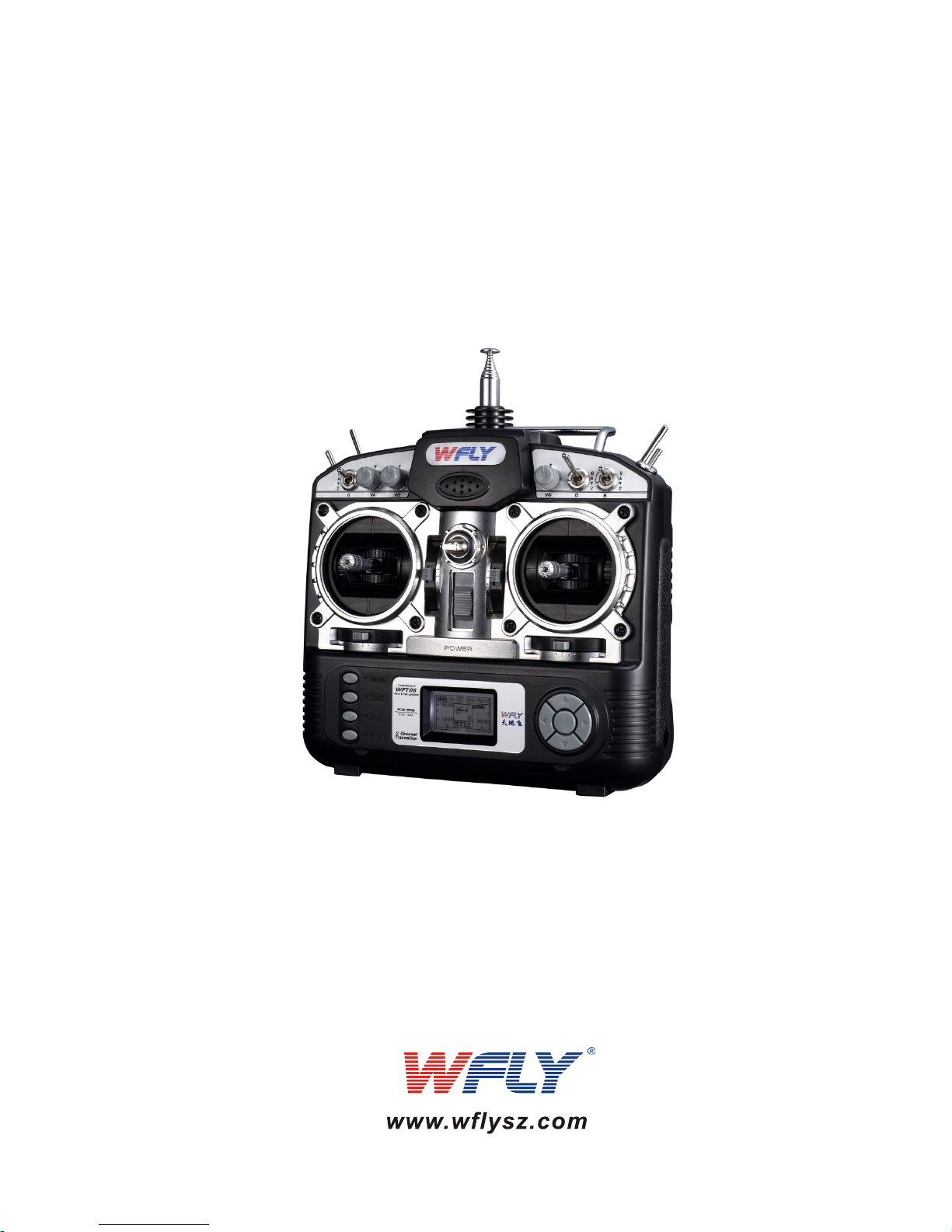
WFT08 RADIO CONTROL SYSTEM PCMS 1024
NOTICE
Read the instructions before operation!
V01
WFT08
INSTRUCTION
Thank you for purchasing a WFLY product!
WFT08
SERVICE
1.Retailers to provide free maintenance for one year (apart from
artificial damage)
2. WFLY retailers will always provide life-long maintance

CATALOGUE
Contents-------------------------------------------------------------------WFT08 Spare parts-------------------------------------------------------Transmitter front-----------------------------------------------------------
Transmitter back-----------------------------------------------------------
Receiver---------------------------------------------------------------------
Trainer function------------------------------------------------------------
Flying safety warnings---------------------------------------------------Features--------------------------------------------------------------------Keys–-----------------------------------------------------------------------Editing mode and function introduction-------------------------------Adjust the stick head-----------------------------------------------------C ---------------------------
1. Model selecting---------------------------------------------------------
2. Model name-------------------------------------------------------------
3. Model setting-----------------------------------------------------------
4. ATL-----------------------------------------------------------------------
5. Modulation setting-----------------------------------------------------
6. Swash select------------------------------------------------------------
7. Stick setting-------------------------------------------------------------
8. Rest setting-------------------------------------------------------------
9. Send data---------------------------------------------------------------
10. Receive data----------------------------------------------------------
11. Contrast setting-------------------------------------------------------
12. Language--------------------------------------------------------------
13.Curve setting----------------------------------------------------------
1. Monitor-------------------------------------------------------------------
2. Dual rate & Exponential-----------------------------------------------
3. Servo reverse-----------------------------------------------------------
4. End point----------------------------------------------------------------
hange the throttle direction of mode1 or 2
WFT08
INSTRUCTION
I
HELICOPTER
SYS SETTING
NORMAL SETTING
01
02
03
04
05
06
07
08
09
1
0
12
13
14
1
5
16
17
18
19
20
21
22
23
24
24
25
26
27
28
29

5. Sub trim----------------------------------------------------------------
6. Swash param setting------------------------------------------------
7. Auxiliary channels setting------------------------------------------
8. Throttle curve setting------------------------------------------------
9. Pitch curve setting---------------------------------------------------
10. Revolution mixing---------------------------------------------------
11. Trim step setting-----------------------------------------------------
12. Throttle cut setting--------------------------------------------------
13. Fly model switch-----------------------------------------------------
14. Throttle holding setting---------------------------------------------
15. Fail safe---------------------------------------------------------------
16. Time-------------------------------------------------------------------
17. Language-------------------------------------------------------------
18. Advance---------------------------------------------------------------
(1). GYRO sens setting-------------------------------------------- (2). Throttle hovering setting--------------------------------------
(3). Pitch hovering setting------------------------------------------
(4). HI/LO PIT Setting-----------------------------------------------
(5). Trim offset setting----------------------------------------------
(6). DELAY------------------------------------------------------------
(7). Governor mixing------------------------------------------------
(8). Swash and THR mixing--------------------------------------- (9). Curve setting----------------------------------------------------
(10). PROG.NOR.MIX1-5------------------------------------------
(11). PROG.CUR.MIX1-2-------------------------------------------
(12). Throttle needle mixing----------------------------------------
WFT08
INSTRUCTION
II
ADVANCED
30
31
32
33
35
37
38
39
40
41
42
43
44
45
46
47
48
49
50
51
52
53
54
55
56
57

WFT08
INSTRUCTION
AIRPLANE
SYS SETTING
1.MODEL SELECTING---------------------------------------------------
2.MODEL NAME-----------------------------------------------------------
3.MODEL SETTING-------------------------------------------------------
4.ATL------------------------------------------------------------------------
5.AIL-2----------------------------------------------------------------------
6.MODULATION SETTING----------------------------------------------
7.STICK SETTING--------------------------------------------------------
8.REST SETTING---------------------------------------------------------
9.SEND DATA--------------------------------------------------------------
10.RECEIVE DATA-------------------------------------------------------
11.CONTRAST SETTING-----------------------------------------------
III
NORMAL SETTING
1.MONITOR----------------------------------------------------------------
2.DUAL RATE & EXPONENTIAL SETTING---------------------------
3.SERVO REVERSE------------------------------------------------------
4.END POINT--------------------------------------------------------------
5.SUB TRIM----------------------------------------------------------------
6.AUXILIARY CHANNELS SETTING----------------------------------
7.THROTTLE CURVE SETTING----------------------------------------
8.TRIM STEP SETTING--------------------------------------------------
9.FLAPERON--------------------------------------------------------------
10.FLAP TRIM-------------------------------------------------------------
11.AIL-DIFF----------------------------------------------------------------
12.ELEV-FLAP------------------------------------------------------------
60
61
62
63
64
65
66
67
68
69
70
71
72
73
74
75
76
76
79
80
81
82
83

WFT08
INSTRUCTION
IV
13.THROTTLE CUT SETTING-----------------------------------------
14.IDLE DOWN-----------------------------------------------------------
15.FAIL SAFE-------------------------------------------------------------
16.TIMER------------------------------------------------------------------
17.ADVANCED------------------------------------------------------------
18.LANGUAGE------------------------------------------------------------
1.CURVE SETTING-------------------------------------------------------
2.PROG.NOR.MIX1-5----------------------------------------------------
3.PROG.CUR.MIX1-2----------------------------------------------------
4.AIR BRAKE---------------------------------------------------------------
5.ELEVON------------------------------------------------------------------
6.AILVATOR----------------------------------------------------------------
7.V-TAIL---------------------------------------------------------------------
8.SNAP-ROLL--------------------------------------------------------------
9.DELAY---------------------------------------------------------------------
10.THROTTLE NEEDLE MIXING---------------------------------------
11.GYRO SENS SETTING-----------------------------------------------
ADVANCED
84
85
86
87
88
89
90
91
92
93
94
95
96
97
98
99
100

Contents
Thank you for your attention and support for WFLY radios!
WFLY promises every WFT08 radio control system include the
following contents:
1. WFT08 transmitter
2. WFTRF01 RF module
3. Battery holder for transmitter
4.Neckstrap
5. Simulator cable
6. WFR08-P software decoding receiver PPM
7. English instruction manual
8.Lithium power step-down device
WFT08
INSTRUCTION
01
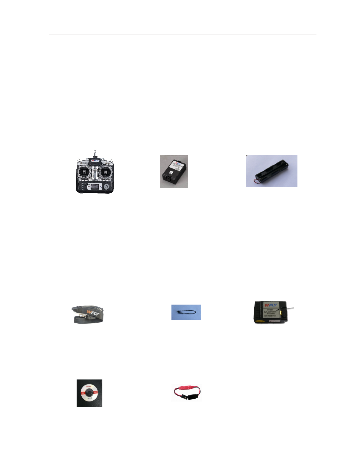
WFT08 Spare Parts
1. Transmitter
2. RF module
3. Transmitter battery
holder
4. Neckstrap
5. Simulator cable
WFT08
INSTRUCTION
6. Software decoding
receiver PPM
02
7.Manual
8.Lithium power
step-down device
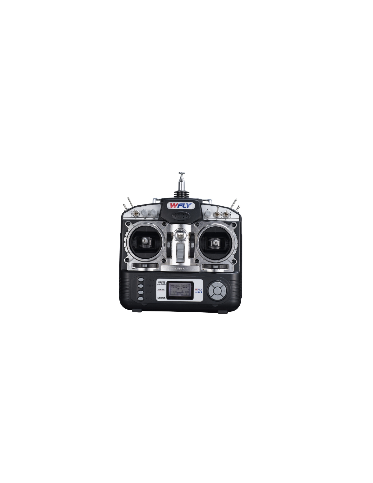
TRANSMITTER FRONT
MODEL NO.: WFT08
MODULATION: PCM/ PPM
OUTPUT POWER: ≤700mW
POWER SUPPLY: 1.2V x 8 (9.6V)
CURRENT DRAIN: 200mA
Band: 35, 36, 40, 41, 72MHz
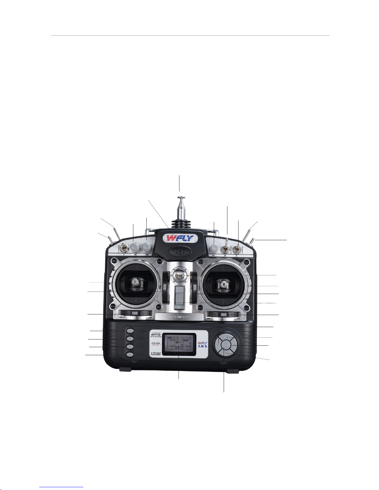
TRANSMITTER FRONT
WFT08
INSTRUCTION
03
Antenna
Buzzer
Decrease
Menu
Exit
Increase
Rudder trim
Elevator tri m
Rudder/ele vator
stick
Switch B
Switc h A
Switch C
VA
VB
VC
Switch F
Tra iner sw itch
Switch D
Neckstrap at tachment
LCD
OK
Down
Right
Up
Left
Aileron trim
Power switch
Throttle tri m
Aileron/th rottle stick
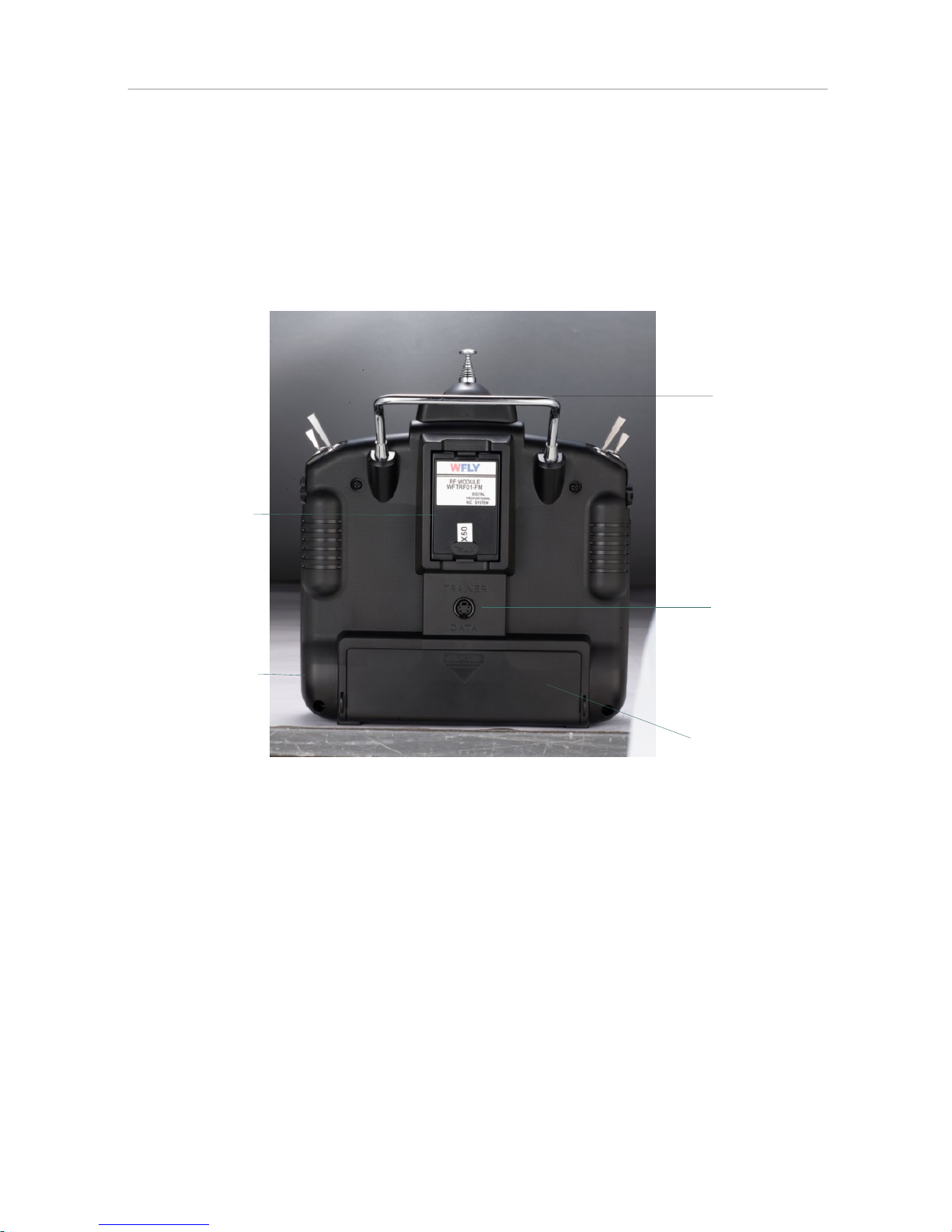
TRANSMITTER BACK
Handle
RF module
Battery cover
DSC
Charge hole
WFT08
INSTRUCTION
04

The receiver is used for WFT09/08 transmitter.
WFR08-P 8 Channels Software decoding Receiver (PPM)
1.AIL:Ail eron (Chan nel 1)--------- -------- -------- -------- -2.ELE:Ele vator (Cha nnel 2)---------------- -------- -------3.THR:Thr ottle (Cha nnel 3)---------------- -------- -------- -4.RUD:Rud der (Chann el 4)---------- -------- -------- -------5.GYR:Lan ding Gear/ Gyro (Channel 5)- -------- -------- --6.PIT:Pit ch (Channe l 6)------ ------------- -------- --- ------ ----
7.AUX1:Au xiliary ch annel 1 (Channel 7) -------- -------- -8.AUX2:Au xiliary ch annel 2 (Channel 8) -------- -------- ---
9.Power:I nput +4.8 -6 V-------- -------- --------------------- -
WFT08
INSTRUCTION
RECEIVER
MODEL NO.: WFR08-P
TYPE: 8CH Software decoding PPM
POWER SUPPLY: 1.2V x 4 (4.8V)
CURRENT DRAIN: 20mA
WEIGHT: 19 g
DIMENSION: 44.88mm x27.90mm x16.39mm
BAND: 35, 36, 40, 41, 72MHz
There is the function of fail safe
05
The setti ng for fail safe:
Receive r connected to the b attery (transmitter don 't be op ened), wait 16 sec onds or so, the red
LED flash es, make sure ever y channel have been putting i n the location you n eed, then open
the trans mitter, (that is the da ta receiver output after th e out- of- control p rotection , for ex ample:
throttl e is set to10%,the d irection is set to 60%, then when entering the ou t-of-control p rotection the
receive r output data is thr ottle 10%, the direction 60 %)

Trainer function
Two WFT08 transmitters can transfer data between each other or
act as trainer.
Setting Method:
1).Data transfer function: use Trainer/Data transfer cable to
interconnect two WFT08 transmitters.
Select “Send data/receive data” in SYS setting to transfer the data.
2).Trainer function: use Trainer/Data transfer cable to connect two
WFT08 transmitters.
Insert RF module to the trainer transmitter, student transmitter
doesn’t insert the RF module.
Flip the Trainer switch to enable the student transmitter. By flipping
the trainer switch again, the student’s transmitter signal will be
disabled and the trainer controls the aircraft exclusively.
WFT08
INSTRUCTION
06

FLYING SAFETY WARNINGS
Dangers:If you use it without proper operation, it is possible that you
burt yourself or others seriously or may even cause death.
Warnings:If you use it without proper operation, it may cause harm to
you and others as well as it could cause damage to third
party property.
Notices:If you use it without proper operation, it may cause you to
hurt slightly or damage things , but it won't hurt you seriously
normally.
Special Symbol Instruction
Forbiddance!
Obligation!
Warning!
Flying Notice(warning)
Same frequencies can't fly at the same time.
Two radios transmitting on the same frequency will
cause an airplane to crash, even when the modulation
(AM, FM, PCM) is different.
Do not fly at night , during rain or in strong wind, as
you risk damaging your equipment. This device is not
water-proof.
Please check that all servos work properly and
eliminate all problems before operating your model.
(If the radio bounces after turning off the power, there
may be some disturbances, in this case, please
change your channel by exchange crystals)
Checking
Notices: Always turn on the transmitter first, then the receiver. When
turning off the system, turn off the receiver first, then the
transmitter.
Notices:Children under 14 must be accompanied and instructed by
adults!
To use the product safely, please pay attention to the instructions
as follows.
Please pay special attention to the symbol as follows:
WFT08
INSTRUCTION
07

FEATURES
Computerized transmitter.
132 x 64 FSTN LCD, easy operating keys.
Metal slab shell.
Adjustable antenna base.
Tightness and length of the control stick can be adjusted freely.
Excellent feeling on the stick.
Full digital trim.
Dully exchangeable RF modules.
Trainer function.
3 independent timer, all can be set to count down or increment.
PPM, PCM and PCMS 1024 modulation supported.
Multi-mixing function.
All curves have up to 7 adjustable points.
User-defined switches and knobs.
Model parameters can be exchanged between transmitters.
8-model memory.
The WFT08 transmitter is compatible with FUTABA and JR (PPM)
receivers.
Our Dual conversion receiver(PPM) is compatible with FUTABA and
JR transmitters.
WFT08
INSTRUCTION
08

MENU
Menu key brings you to the function list of the transmitter.
EXIT
Exit key brings you back to the previous menu or exit edit.
+
This key will increase values. If you long press, the increasing
speed will be faster.
-
This key decreases values. If you long press, the decreasing speed
will be faster.
Cursor keys
Move the cursor.
OK
The key in the center of the direction keys is the OK key.
It has following functions:
Enter the function list.
Enter the edit function.
Change parameters back to default by long pressing the key.
Keys
WFT08
INSTRUCTION
09

1. Start up Screen
The starting up screen displays the voltage, timer, model, aileron,
throttle, elevator and rudder fine-tuning state.
2. Menu Screen
You will find the “System setting”, “SYS setting”, “More setting”.
When turn on the power switch, the LCD displays as follows.
A. System setting
Turning on the transmitter and pressing the menu key, the LCD
displays the follows.
1. MONITOR
2. DUAL RATE & EXPONENTIAL SETTING
3. SERVO REVERSE
4. END POINT
5. SUB TRIM
6. SWASH PARAM SETTING
7. AUXILIARY CHANNELS
8. THROTTLE CURVE SETTING
9. PITCH CURVE SETTING
10. REVOLUTION MIXING
11. TRIM STEP SETTING
12. THROTTLE CUT SETTING
13. FLY MODEL SWITCH
14. THROTTLE HOLDING SETTING
15. FAIL SAFE
16. TIMER
17. ADVANCED
18. LANGUAGE
Voltage
Start tim e
Timer A
Timer B
Timer C
Model typ e
Throttl e trim
display
Rudder tr im display Aileron t rim display
Elevato r trim display
Modulat ion
Editing mode and function introduction
Note: Press EXIT, the screen shows you the model name.
Setting method:
1. Use direction keys change
parameters or use the up/down keys to
browse the functions. Use the left/right
key to switch pages.
2. Press OK to enter submenu.
The submenu function is described in
the next chapter.
3. Press EXIT key to go back from
previous menus. Data is set automatically.
WFT08
INSTRUCTION
Model nam e
10
HELICOPTER
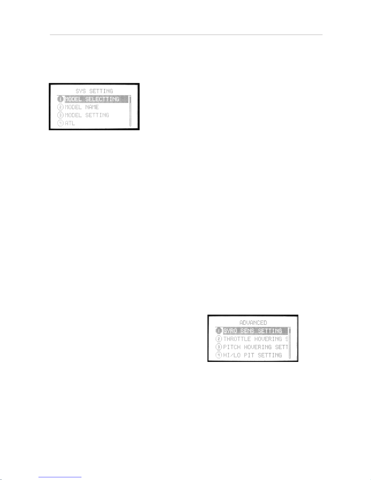
B. SYS SETTING
When pressing Menu and turning on the power switch, the LCD
displays the following.
1. MODEL SELECTING
2. MODEL NAME
3. MODEL SETTING
4. ATL
5. MODULATION SETTING
6. SWASH SELECT
7. STICK SETTING
8. REST SETTING
9. SEND DATA
10. RECEIVE DATA
11. CONTRAST SETTING
12. ENGINEER MODE
13. ABOUT
14. LANGUAGE
Setting method:
1. Use direction keys to edit, or use
up/down keys to browse the functions.
Left/right direction keys to switch pages.
2. Press OK key to enter submenu.
The submenu function is described in
the next chapter.
3. Press EXIT key to go back to previous
menu, parameters are saved automatically.
C. ADVANCED
1. Enter “NORMAL SETTING”, use the right direction key to switch
page, select “ADVANCED”.
Press OK key to enter.
Setting method:
1. Use direction key to select the editing mode, use up/down keys
to select a function item. Use the left/right direction keys to switch
page.
2. Press the OK key to enter submenu. The submenu function will
be explained in the next chapter.
3. Press EXIT key to back from previous menu. Data is set
automatically.
WFT08
INSTRUCTION
11
HELICOPTER
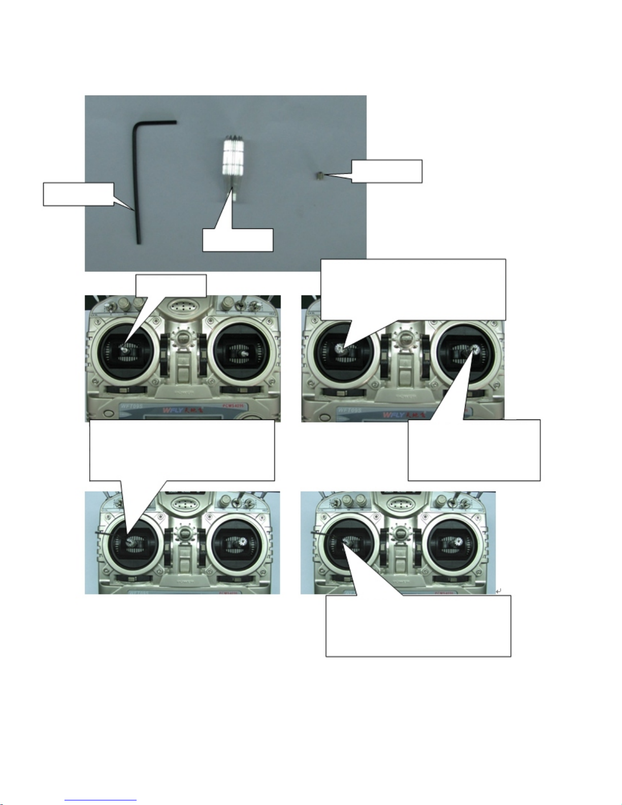
Allen key
Top thread
stick hea d
Stick
Put the stick head cover the contro l rod
on the left and right sides,don't twist down
the st ick head to the bottom, an d then put
top thread with allen key to adjust the
height you need.
Adjust th e heigh t higher: f rist ma ke the top
thread loo se with the allen key, then twist
the st ick he ad up, th en, ma ke the to p
thread tighten with allen key, Ok, the stick
head was turned up.
Twist the top thread down
from here, the height of the
stick head d epend s on the
depth of the top thread.
Adjust the h eight lowe r: fr ist make the
top thread loos e wi th the allen key, then
twist th e stick head do wn, then, make the
top thread tig hten with allen key, Ok, th e
stick head was turned down.
steps:
1
2
Put the sti ck head on the stick .
Put the top t hread in the stick h ead with allen key.
3. Addjust top t hread in the stick h ead with allen key to fix the hei ght
of the stic k head.
12
Adjust the stick head:
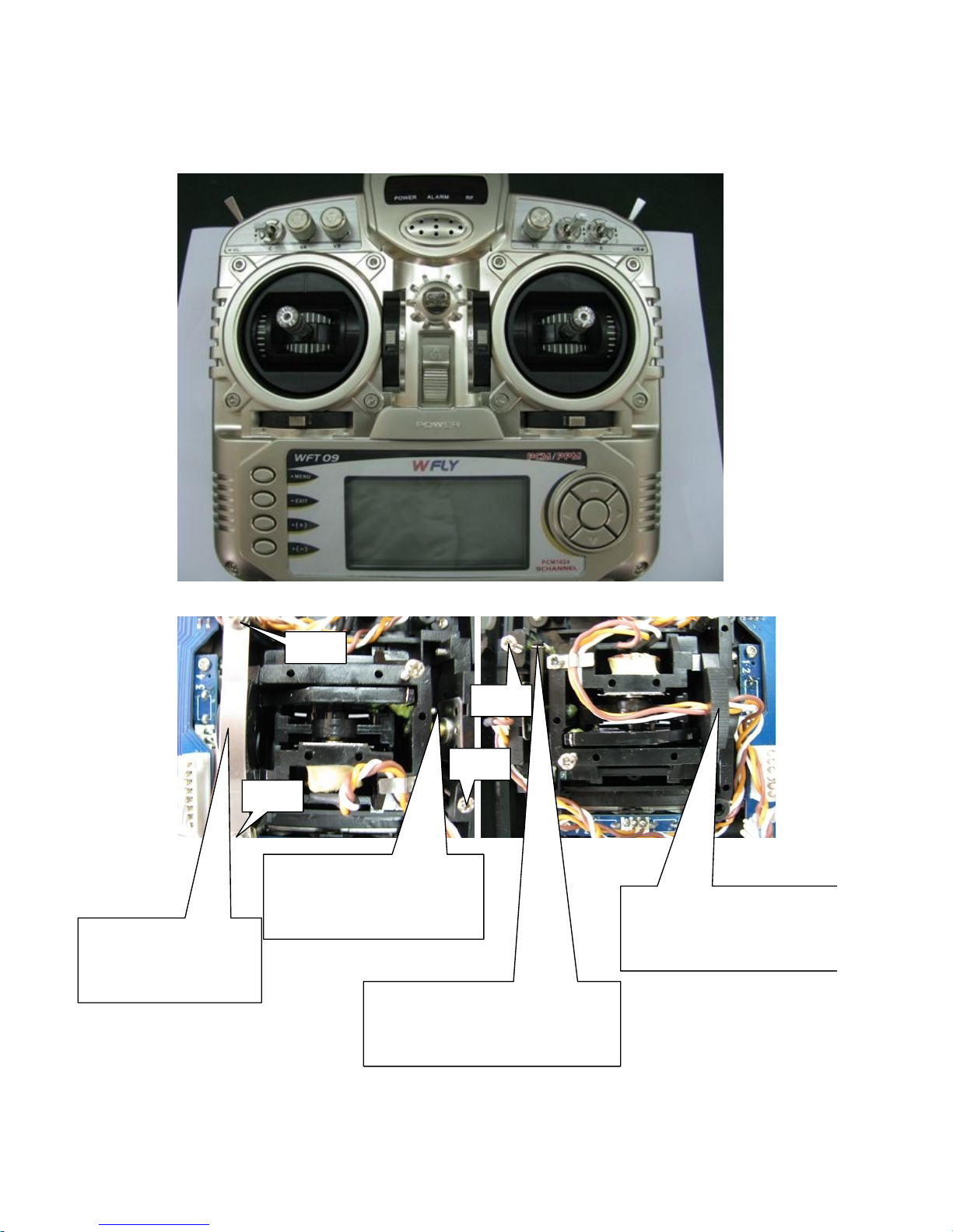
Bo lt
1
Bo lt 2
Bo lt 3
Bo lt 4
13
change the throttle direction of mode1 or 2
Take the metal chip and
the screw down, and put
it on the similar position
of the right side .
Set up release link and
springer, according your habit
to addjust the the tightness of
screw 2 to adjust the control
feeling.
Take repositor and spring down, and
put it on the left side of the location
of corresponding.then twist bolt 1
down until withstand the adjust nail
in case adjust nail will move away.
Put on the metal chip, according
your habit to adjust the elasticity
of screw 3 and screw 4 to adjust
the damp of throttle control
feeling.

HELICOPTER
Press Menu and turn on the transmitter to enter SYS SETTING.
Select MODEL SETTING, press OK key to select the model type.
Restart the transmitter after setting.
WFT08
INSTRUCTION
HELICOPTER

1.Model selecting
There are 8 helicopter models. You can select any one to set.
Setting Method:
Press Menu and turn on the transmitter to enter “SYS SETTING”.
Use up/down keys to select “Model selecting”, OK to enter
editing.
Steps:
1. Use up/down direction keys to select the model.
2. Press OK to select.
3. Press EXIT after setting.
SYS SETTING
WFT08
INSTRUCTION
14
HELICOPTER

2. Model name
This function is to make new names by users.
Setting Method:
Press Menu and turn on the transmitter to enter “SYS SETTING”
Use up/down button to select “Model name”, OK key to enter
editing.
Steps:
1. You can edit the underlined letter.
2. Press OK key to choose the word you like.
3. Press EXIT after setting.
WFT08
INSTRUCTION
15
HELICOPTER

3. Model setting
You can select the model type. There are two types: HELI,
ACRO.
Setting Method:
Press Menu and turn on the transmitter to enter “SYS SETTING”
Use up/down key to select “Model setting”, OK to enter editing.
Steps:
1. Use up/down key to select the model type.
2. Press OK to confirm.
3. Press EXIT after setting.
WFT08
INSTRUCTION
16
HELICOPTER

The adjustable travel limit (ATL) makes throttle trim effective only
at low throttle, disabling the trim at high throttle. This prevents
pushrod jamming due to idling trim changes. This function is ON by
defaults. If you are not using channel 3 for throttle, you may want
trim operation the same as on all other channels. To do so, set ATL
to OFF.
Setting Method:
Press Menu and turn on the transmitter to enter “SYS SETTING”
Use up/down key to select “ATL”, OK to enter editing.
Steps:
1. Use direction keys to select the editing part.
2. Press +/- keys to set ATL function.
3. Press EXIT after setting.
4. ATL
WFT08
INSTRUCTION
17
HELICOPTER

Because of the different receiver modulation, PPM/PCM
PCMS 1024, the transmitter has to be set in accordance
with the receiver modulation.
/
Setting Method:
Press Menu and turn on the transmitter to enter “SYS SETTING”.
Use up/down key to select “Modulation setting”, OK to enter
editing.
Steps:
1. Use direction keys to select the editing part.
2. Press OK to confirm. Restart the transmitter and it works.
5.Modulation setting
WFT08
INSTRUCTION
18
HELICOPTER

6.Swash select
Setting Method:
Press Menu and turn on the transmitter to enter “SYS SETTING”.
Use up/down keys to select “Swash select”, OK to enter editing.
Steps:
1. Use direction keys to select the editing part.
2. Press +/- keys t o choose the swash type.
3. Press EXIT after setting.
There are 6 kinds of swash. You can select the swash you preferred.
If you use a 120 degree CCPM helicopter, the servos will realize mix
function automatically. Please select the swash according to your
helicopter swash type.
1 servo (not CCPM, normal helicopter)
2 servos (180 degree)
3 servos (90, 120, 140 degree)
4 servos (90 degree)
WFT08
INSTRUCTION
19
HELICOPTER

7.Stick setting
There are 4 kinds of model, you can use up/down direction
key to select the model you prefer.
Setting Method:
Press Menu and turn on the transmitter to enter “SYS SETTING”
Use up/down button to select “Stick setting”, OK to enter
editing.
Steps:
1. Use direction keys to select the editing part.
2. Press up/down keys to choose Stick mode.
3. Press EXIT after setting.
1-aileron
2-elevator
3-throttle
4-rudder
WFT08
INSTRUCTION
20
HELICOPTER

This function resets your transmitter to default.
Setting Method:
Press Menu and turn on the transmitter to enter “SYS SETTING”.
Use up/down keys to select “Rest setting”, OK to enter editing.
Steps:
1. Use direction keys to select the editing part.
2. Press +/- keys to back default.
3. Press EXIT after setting.
8.Rest setting
WFT08
INSTRUCTION
21
HELICOPTER

9. Send data
Two transmitters (WFT08) can copy data using the trainer/data
transfer cable. This function and the next one “Receive data” can
be used to copy data between transmitters.
Setting Method:
Press Menu and turn on the transmitter to enter “SYS SETTING”
Use up/down keys to select “Send data”, OK to enter editing.
Steps:
1. Select the model data you want to send out.
2. Press OK to send.
WFT08
INSTRUCTION
22
HELICOPTER
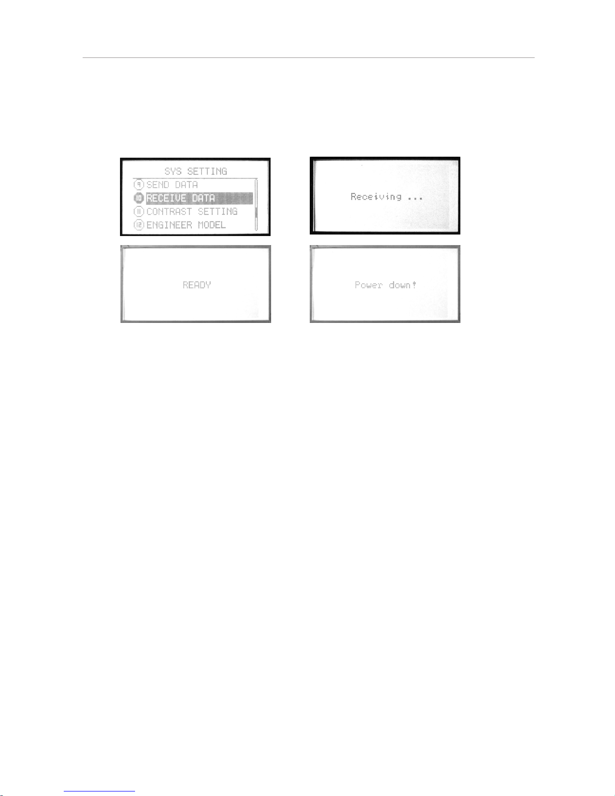
10.Receive data
Two transmitters (WFT08) can copy data by a trainer/data transfer
cable. This function and the next one “Send data” can be used to
copy data between transmitters.
Setting Method:
Press Menu and turn on the transmitter to enter “SYS SETTING”.
Use up/down keys to select “Receive data”, OK to enter editing.
Steps:
1. Press OK to receive data.
2. Restart the transmitter after receiving the data and it works.
WFT08
INSTRUCTION
23
HELICOPTER
 Loading...