

Wfly ET12 Instruction Manual

WFLY
Shenzhen WFLY Technology Development Co., LTD
INSTRUCTION MANUAL
ET12
(ET Series)12-channel Digital Proportional R/C System
001
V1.0 2

Thank you for using WFLY products!
● Please read this product manual carefully before using this product!
● Please use this product correctly!
The model is not a toy, for safety,please don't fly in crowded places!
——Shenzhen WFLY Technology Development Co., LTD
002

CATALOGUE
000
007
007
008
009
009
009
000
000
010
010
011
012
012
000
000
013
014-015
016
016
017
018
000
019
020
021
022
000
000
023
024-025
\Safety Precautions
Symbols Definition
Flying Precautions
Battery
Headphone Port
Trainer Port
USB Port
\Before Use
Basic Configuration
Product Features
Each Parts Name Of Transmitter
The Travel of Antenna Direction Adjustment
Switch Configuration and Model Types
\Basic Operation
Home Interface Introduction
Touch Screen Operation
Stick Adjustment
Indicator Light of Transmitter
Left and Right Hand Mode Replacement Method
Receiver Instructions
Receiver and servo connection example:
--Airplane
--Glider
--Helicopte
--Multicopter
\Basic Setting Sequence of Models
--Airplane and Glider
--Helicopter
003
CATALOGUE
000
026
027
028
029
030
031
032
033
034
035
036
037
038
039
040
000
000
041
042
043
044
045
046
047
048
049
050
051
052
000
000
053
054
055
056
057
058
059
060
061
062
063
064
065
066
\System Setting
Trainer
Display
User Name
Sound
Warning
Low Battery
Stick Mode
Calibration
Telemetry Voice
Back Colour
Language
Screen Cali(Calibration)
Data Reset
Information
Screen Lock Set
\Linkage Setting
Link
Telemetry
PPM/W.BUS
Receiver Output
Fail Safe
Relay Flight
Servo Frequency
BUS Servo Setting
Range Check
Telemetry Unit
180/270° Servo
\General Menu
Monitor
Model Select
Model Type
Function
Servo Reverse
Dual Rate
End Point
Timer
Trim Setting
Sub-Trim
Channel Delay
Program Mixes
Flight Mode
Doublel Engine
004

CATALOGUE
000
067
068
069
070
071
072
073
074
075
076
077
078
079
080-081
000
000
082
083
084
085
086
087
088
089
090
091
092
093
094
095
096
097
098
099
100
101
102
103
\Model Menu\Helicopter
Condition
Pitch Curve
Throttle Curve
Throttle Hold
Throttle Cut
Gyro
Swash Ring
Swash Mixing
Throttle Mixing
Idle Down
Governor
Pitch→Rudder
Fuel Mixes
Swash
\Model Menu\Airplane
Condition
AIL Differential
Throttle Curve
Throttle Cut
Throttle Hold
Idle Down
Aileron→Rudder
Rudder→Aileron
Rudder→ELE
Snap Roll
Flap Setting
Camber Mix
ElE to Camber
Camber Flap to Elevator
Aileron to Camber Flap
Airbrake
Gyro
Motor
Fuel Mix
Elevator
V-Tail
Winglet
005
CATALOGUE
000
104
105
106
107
108
109
110
111
112
113
114
115
116
117
118
119
120
121
122
123
000
000
124
125
126
127
128
129
\Model Menu\Glider
Condition
AIL Differential
Throttle Curve
Throttle Cut
Throttle Hold
Idle Down
Aileron→Rudder
Rudder→Aileron
Flap Setting
Camber Mix
Elevator to Camber
Flap to ELE
Aileron to Flap
Butterfly
Trim Mixing
Gyro
Motor
V-tail
Aileron Elevator
Winglet
\Model Menu\Multicopte
Condition
Throttle Curve
Throttle Cut
Throttle Hold
Stick Alarm
Gyro
006

Safety Precautions
WARNING
NOTICE
DANGER
WARNING
NOTICE
DANGER
Symbols Definition
Pay special attention to the safety information of the following symbols.
If without a proper operation,it may cause dangerous accident or seriously injury or
may even cause death.
If without a proper operation,it may cause dangerous accident or seriously injury or
may even cause death,and it may cause slight hurt or probability cause bodily injure!
If without a proper operation,it may cause less possibility to serious hurt,but it may
cause hurt or bodily injure.
Prohibitions
Flying Precautions
Disclaimer & Warning
User should be responsible for any consequences
caused by using the product. WFLY shall not be
liable for any directly or indirectly damage, injury
and any legal liability, User shall comply with all
guidelines including but not limited to this
document.
Please follow the local laws and regulations for
regular flight activities. Do not use this product to
carry out personal safety, property safety or other
bad flight behaviors.
To ensure the safety of yourself and others,
please observe the following precautions:
Charge the batteries! Check transmitter and
receiver battery levels and always recharge the
batteries before each flying session. A low battery
will soon die potentially, causing loss of control and
a crash. When you begin your flying session, reset
your ET12 built-in timer, and during the session pay
attention to the duration of usage.
Be careful when flying near electric wires, highrise buildings or communication facilities, as there
may be radio interference around.
Mandatory
Before flying, inspect the aircraft carefully,
inspect whether the aircraft and transceiver system
it's normal. When flying, make the transmitter
display to the initial interface, in case of mistaken
parameter change. After flight, turn off the receiver
power before turn off the transmitter power, in case
of any injury caused by fail safe works.
More debugging, more testing, less loss, less
damage!
Mandatory
Power on and off sequency of transmitter and
receiver
Power on:
Firstly turn on the transmitter (ensuring the
minimum throttle position), Secondly Turn on the
receiver
Power off:
Firstly turn off the receiver, Secondly turn off the
transmitter
Transmitter and receiver low voltage may cause
fail-safe danger!
Beginners should pay particular attention to the
following safety precautions! Please read carefully!
No fly when user is in poor health condition such as
fatigue and drunkenness.
No fly in bad weather day such as rain, strong wind
or at night, etc.
No fly near high voltage wires, communication base
stations, government secret zone or public places
where crowds gathered.
No fly in airports and other places where fly is
forbidden.
Mandatory
Note: The transmitter will display the warning
interface, please pay attention to the transmitter
prompt! Improperly operation may cause
accident injury to user.
007

Safety Precautions
DANGER
NOTICE
NOTICE
Battery
Lithium polymer battery(Short for LiFe
battery),please use the WFLY special charger
only.It is important to understand the operating
characteristics of Li-FE batteries.
IMPORTAN!
Long term storage (more than 3 months),storage
temperature≤45°C general storage voltage 3.7-
3.9v.Failure to follow the proceeding precautions
can quickly result in severe, permanent damage to
the batteries and possibly result in a fire!
1.Do not attempt to disassemble LiFe packs or
cells.
2.Do not allow LiFe cells to come in contact with
moisture or water at any time.
3.Always provide adequate ventilation around
LiFe batteries during charge, discharge, while in
use, and during storage.
4.Do not leave a LiFe battery unattended at any
time while being charged or discharged.
5.Do not attempt to charge LiFe batteries with a
charger that is NOT designed for LiFe batteries, as
permanent damage to the battery and charger could
result.
6.Always charge LiFe batteries in a fireproof
location. Do not charge or discharge LiFe batteries
on carpet, a cluttered workbench, near paper,
plastic, vinyl, leather or wood, or inside an R/C
model or full-sized automobile! Monitor the charge
area with a smoke or fire alarm.
7.Do not charge LiFe batteries at currents greater
than the “1C” rating of the battery (“C” equals the
rated capacity of the battery).
8.Do not allow LiFe cells to overheat at any time!
Cells which reach greater than 140 degrees
Fahrenheit (60°C) should be placed in a fireproof
location.
9.LiFe cells will not charge fully when too cold or
show full charge.
10.It is normal for the batteries to become warm
during charging, but if the charger or battery
becomes excessively hot disconnect the battery
from the charger immediately!! Always inspect a
battery which has previously overheated for
potential damage, and do not re-use if you suspect it
has been damaged in any way.
11.Do not use a LiFe battery if you suspect
physical damage has occurred to the pack.
Carefully inspect the battery for even the smallest of
dents, cracks, splits, punctures or damage to the
wiring and connectors.DO NOT allow the battery’s
internal electrolyte to get into eyes or on skin—wash
affected areas immediately if they come in contact
with the electrolyte. If in doubt, place the battery in a
fire-proof location for at least 30 minutes.
12.Do not store batteries near an open flame or
heater.
注意
13.Do not discharge LiFe batteries at currents
which exceed the discharge current rating of the
battery.
14.Always store LiFe cells/packs in a secure
location away from children.
Transmitter (ET12):
ET12 adopts the power supply mode of lithium
battery, and the working voltage adapts to the range
of 3.5V-13V. Using a power supply that exceeds the
operating voltage stroke may burn the machine!
The USB interface of the ET12 cannot be
charged. Please charge the battery with a
professional charger!
Receiver (RF209S):
The receiver's operating voltage adapts to the
range 3.5V-13V, with anti-reverse protection slot
(power input pole, positive and negative reverse
protection). With a power supply that exceeds the
operating voltage stroke, the receiver will burn out.
008
Safety Precautions
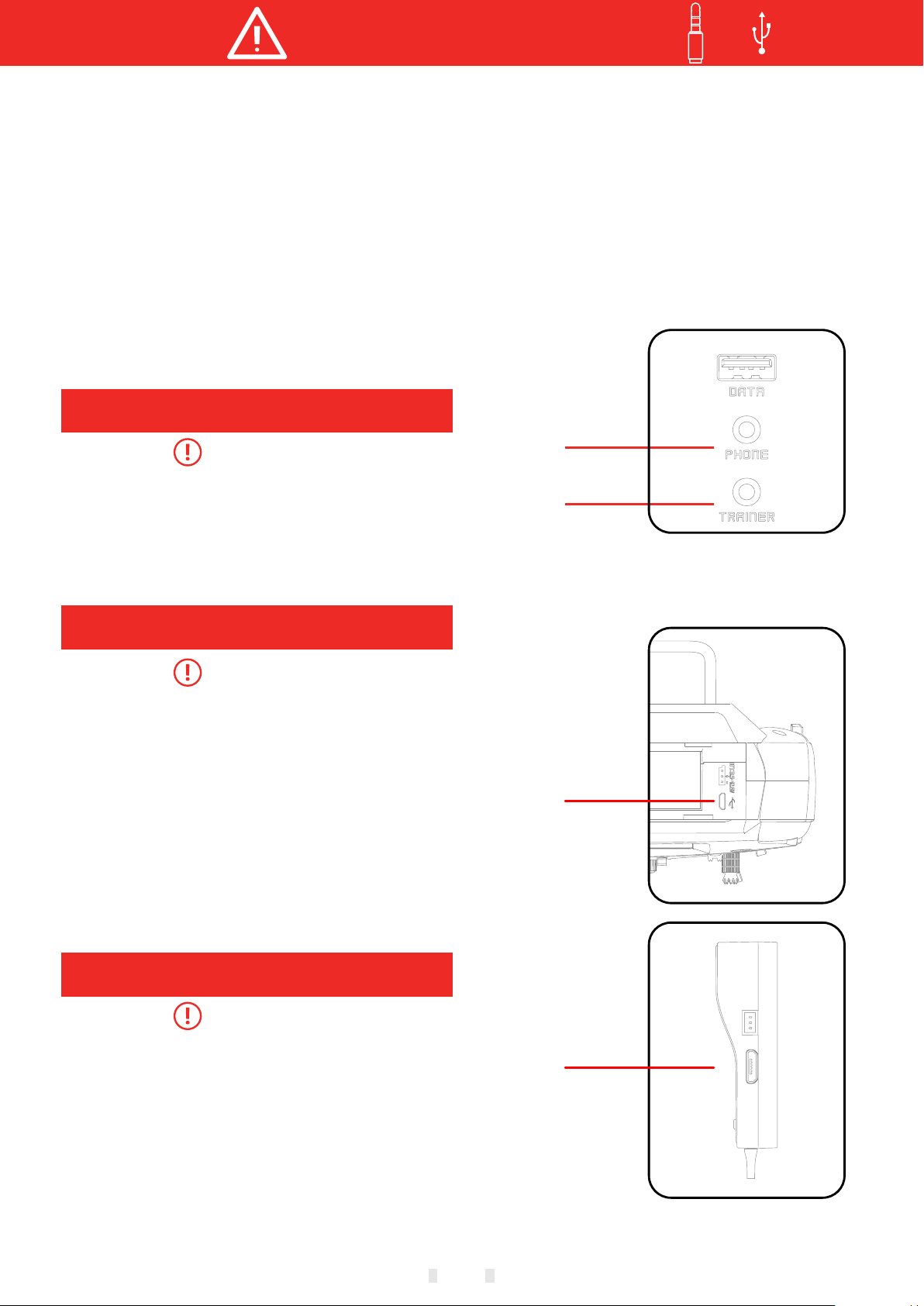
Headphone Port
Mandatory
Headphone port
Transmitter headphone port:
Only for voice output! Standard:3.5mm audio
port. Warning: This port is only used as a voice port.
Do not insert the charging (high voltage) terminal
into the port to avoid damage to the transmitter.
Trainer Port
Mandatory
Transmitter trainer port:
The trainer port is with 3.5mm audio port output
mode. This suite is without the trainer data line. If
you want to use the trainer function, you need to
purchase the trainer data line separately! Warning:
This port is only used for trainer data transmission.
It is forbidden to insert the power supply (high
voltage) terminal to the port to avoid damage for the
transmitter. Suggestion: You can consult the
purchase line at WFLY Technology Taobao Store or
other model online stores or physical stores.
Trainer port
USB port
USB Port
Mandatory
Transmitter USB port:
ET12 adopt standard USB port for upgrading
function! Warning: This port is only used as
upgrading data transmission, it is forbidden to insert
the power supply (high voltage) terminal to the USB
port to avoid damage for the transmitter.
Receiver USB port:
RF209S USB port is only used as upgrading data
port, it is forbidden to insert the power supply (high
voltage) terminal to the USB port to avoid damage
for the receiver.
USB port
009
Before Use
Product Features
Transmitter
Type: ET12
Channel: 12
Voltage: 3.5V-13V(1S-3SLithium battery)
Current: 260-400mA
Application: Helicopter, Airplane, Multi-rotors,
Vehicle, Ship.
Resolution: Full Channel 4096
Band: 2.4GHz (Bidirectional)
Storage: 30 models
Programming: 5 Groups Mixed Control
Language: Chinese, English
Upgrading:USB online upgrade
Display: 3.5inch touch, 480*320, color display
Voice: Support voice broadcast
Relay light: Available
180/270°Servo: Available
Wireless signal copy: model data
Receiver
Type: RF209S
Band: 2.4GHz
Voltage: 3.5V-13V
Current: 95mA
Application: Helicopter, Airplane, multicopter,
Vehicle, Ship, Robot.
Resolution: 4096
PWM: 9channels
W.BUS: Compatible
W.BUS2: Remote sensor input
Two-way transmission: Available
Lost-control protection: Available
Online upgrading: Available
Relay flight: Available
180/270°servo: Available
Receiver port setting: Available
External voltage detection: DC 0~96V
Dimension: 47x14x25mm
Weight: 12g
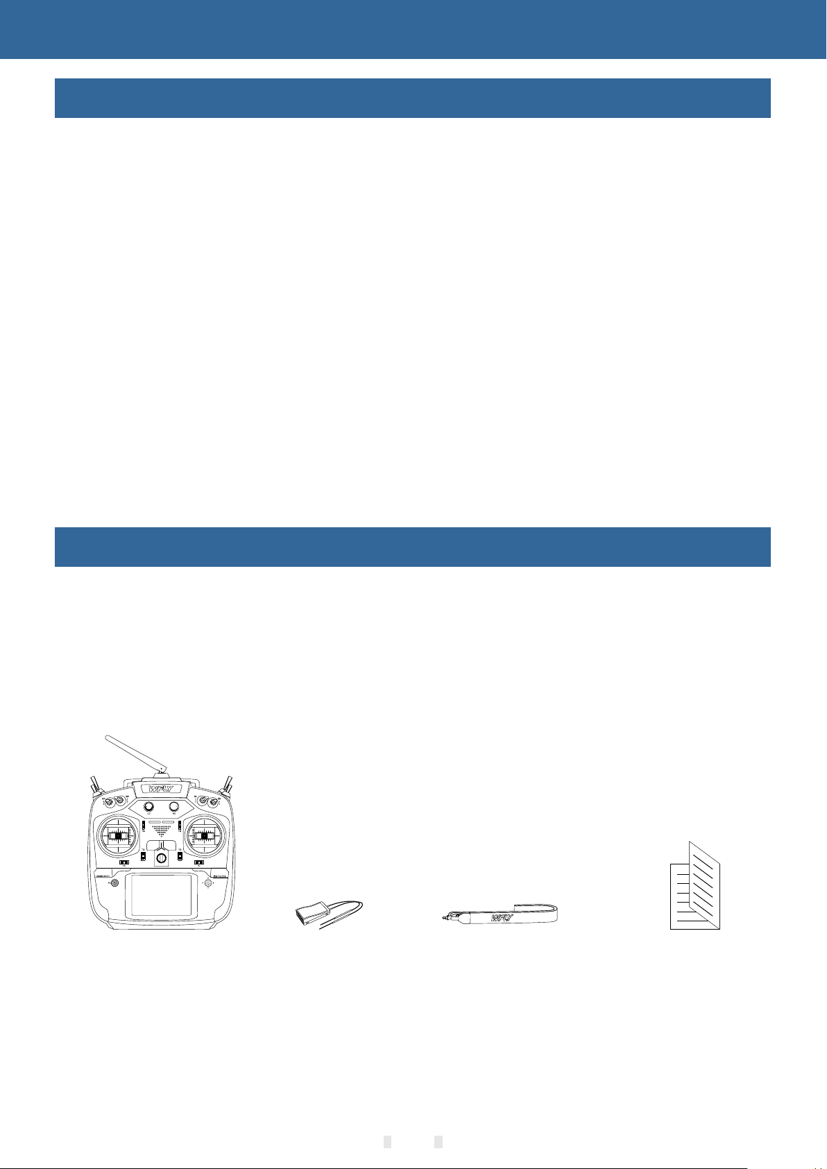
Basic Configuration
ET12 transmitter x1
RF209S receiver x1(include external power detection line x1)
Hanging strap x1
Summary manual x1
①
Transmitter
②
Receiver
010
③
Hanging Strap
④
Summary Manual

Carr y handle
Before Use
Each Parts Name Of Transmitter
Antenna
SF Switch Block
SE Switch Block
SB Switch Block
SA Switch Block
LD Rotary Knob
J3
J4
HOME/MON.
Fn Toggle Key
Fn Status LED
Power LED
Trim6
Stick
Power key
Trim3
Trim4
SH Switch Block
SG Switch Block
SC Switch Block
SD Switch Block
RD Rotary Knob
RF LED
Trim5
Speaker
Stick
Trim2
Trim1
EXIT/LOCK
5-way Button
Hook
J2
J1
Color LCD
VR Thumb Wheel
RS Slide Lever
Headphone Port
Trainer Port
Battery cover
VL Thumb Wheel
LS Slide Lever
Battery Interface
USB Port
011

Before Use
Switch configuration and model types
Power LED: Left, power indicator light, red
RF LED: Right, RF indicator light, blue.
POWER: Click one power key only for 3 seconds to open/shut down; Click 2 pow er k ey s at t he s am e ti me
to flash shutdown.
SA: Short lever 3 positions (user-defined)
SB: Long lever 3 positions (user-defined)
SC: Long lever 3 positions (user-defi ne d)
SD: Short lever 3 positions (user-defined)
SE: Short lever 3 positions (user-defined)
SF: Short lever 3 positions (user-defined)
SG: Short lever 3 positions (use
SH: Long lever momentary (user-define d)
LS/RS: Slide lever (user-defined)
VL/VR: Thumb wheel (user-defined)
T1-T6: Trim (user-defined)
5-way button: Move the cursor button up and down or left and right, middle button for confirmation(Long
press for momentary)
Fn switch key: Click to switch for 5-way button working mode. Fn status LED lighting-o ff, 5-w ay b ut to n
works for interface operation setting and parame ters inp ut w he n to uc h sc re en i s ou t of w or k( PS : 5- wa y
button and touch panel could be used at the sa me tim e) . Fn s ta tu s LE D is o n, 5 -w ay b ut to n wo rk s as c
switch, click button or trimming.
r-defined)
ontrol
PHONE: Earphone plug in the earphone tra ns mi tt er s pe ak er, m ea nw hi le e arphone output the voice.
TRAINER: Trainer port.
HOME/MON.: Home/Monitor key, short click home, long click monitor.
EXIT/LOCK: Exit/Lock key, short click to exist, long click to lock the screen.
The Travel Of Antenna Direction Adjustment
The antenna activity of the transmitter is limited by the stroke. If the activity is exceede d, t he a nt en na w il l
be damaged. The active travel indication of the antenna is as following:
Mandatory
Up and down 90°
Rotate 180° on the front
012

Basic Operation
WFLY
Home Interface Introduction
18
17
1
2
3
Home Interface 1
4
5
6
7
Introduction and Operation
1.Transmitter model
2.LOGO, Click to enter main menu
3.Timer 1
4.Return data(receiver voltage)
5.Return data(External battery)
6.Model active time,switch model,long press,
reset shutdown.
7.Trim monitor,display active trimming
status(Right side diagram)
8."HPME2" key,click to enter home Interface 2
9.Model name: Click to enter models select
interface
10.Model Type:Click to enter current model type
Interface
11.Timer 2
12.User name,click into user defined name
13.Indicate trim status,display the current trim
position
14.Transmitter battery voltage
15.Receiver signal strength
16.Flight condition,current flight mode
17.Trainer mode(Trainer/Simulator/Student)
18.Lock(Click and hold EXIT/LOCK buttom for 2s
ET12
00:00.0
Receiver
00:00.0
-500 -500
5.0V
12.0VExternal
16
T5
T6
+25
0 +1000
HOME2
8
to enter lock status)
15
T6
T3
14
13
12
11
10
9
T5
T2
T1
12.9V
T2 T1
T4
+1000
RXCondition1SIM
T3
User name
00:00.0
Model 1
T4
19."HOME1 interface1",click into home interface
20.Return data(Receiver voltage)
21.Timer 1
22.Timer 2
23.Return data(Ext battery voltage)
Home Interface 2
19
20
21
22
HOME1
Receiver
5.0
SIM
Condition1
RX
External
V
12.0
00:00.0
00:00.0
013
12.9V
23
V
Basic Operation
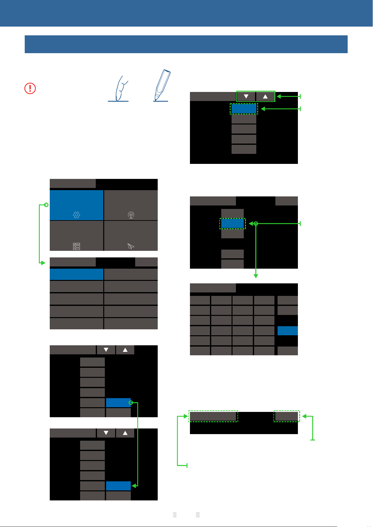
Touch Screen Operation
ET12 uses 3.5 inches resistive touch screen,
which makes ET12 operation more flexible and
efficient.
Mandatory
Touch softly the Touch Screen with the stylus pen
or your fingertips.Plastic film is attached to the touch
screen. Please be careful so that you don't scratch
the touch screen with anything hard such as a metal
object. Don't push the touch screen with excessive
force or drop anything on the panel.
Operate Demonstration
Menu Operation:Click enter into the relative
interface
Menu
System setting
General menu
System setting
Tra iner
Linkage setting
Model menu
1/2
Low battery
Parameters Setting
1 Data setting:Click and pop up the upper right
setup key,press long for rapid add and
subtract.Long Press the number button to reset the
default value.
Telemetry voice
Status
Switch
Speed interval
Alarm repeat
Alarm duration
ON
--
30 Sec
1
10 Sec
Setting Button
Long Press to
reset the
default value
2 Switch Selection:Click switches selecting
button,choose the required switch from the switches
selecting interface
Tra iner
Mode
Teach SW
CH mode
CH
Aileron
1
Rudder
2
Tra iner
--
12CH
Status
ON
ON
1/2
Jump to the
interface of
the distribution
switch button
Display
User name
Sound
Warn ing
Stick mode
Calibration
Telemetry voice
Back colour
Status Switch: Click into switch status
Sound
Warn ing
Telemetry
Button
Other
Tri m
Tim er
Sound
Warn ing
Telemetry
Button
Other
Tri m
Tim er
50
50
50
50
50 Voice
50 Voice
50
50
50
50
50 Voice
50 Voice
Tra iner
J1
J2
J3
J4
LD
RD
SA
SB
SC
SD
LS
RS
SE
SF
SG
SH
VL
VR
T1
T2
T3
T4
T5
T6
C L/R
C U/D
--
Diagram
Return,Paging Operation
Return:Click pages button to switch interface
Paging:Click paging button to switch
interface,when multiple page,the upper right of
interface indicates A/B style (A,current page;B page
numbers)
Tra iner
1/2
This shows the first page interface,
a total of two pages.
Click to return to the previous interface
014
Basic Operation
Touch Screen Operation
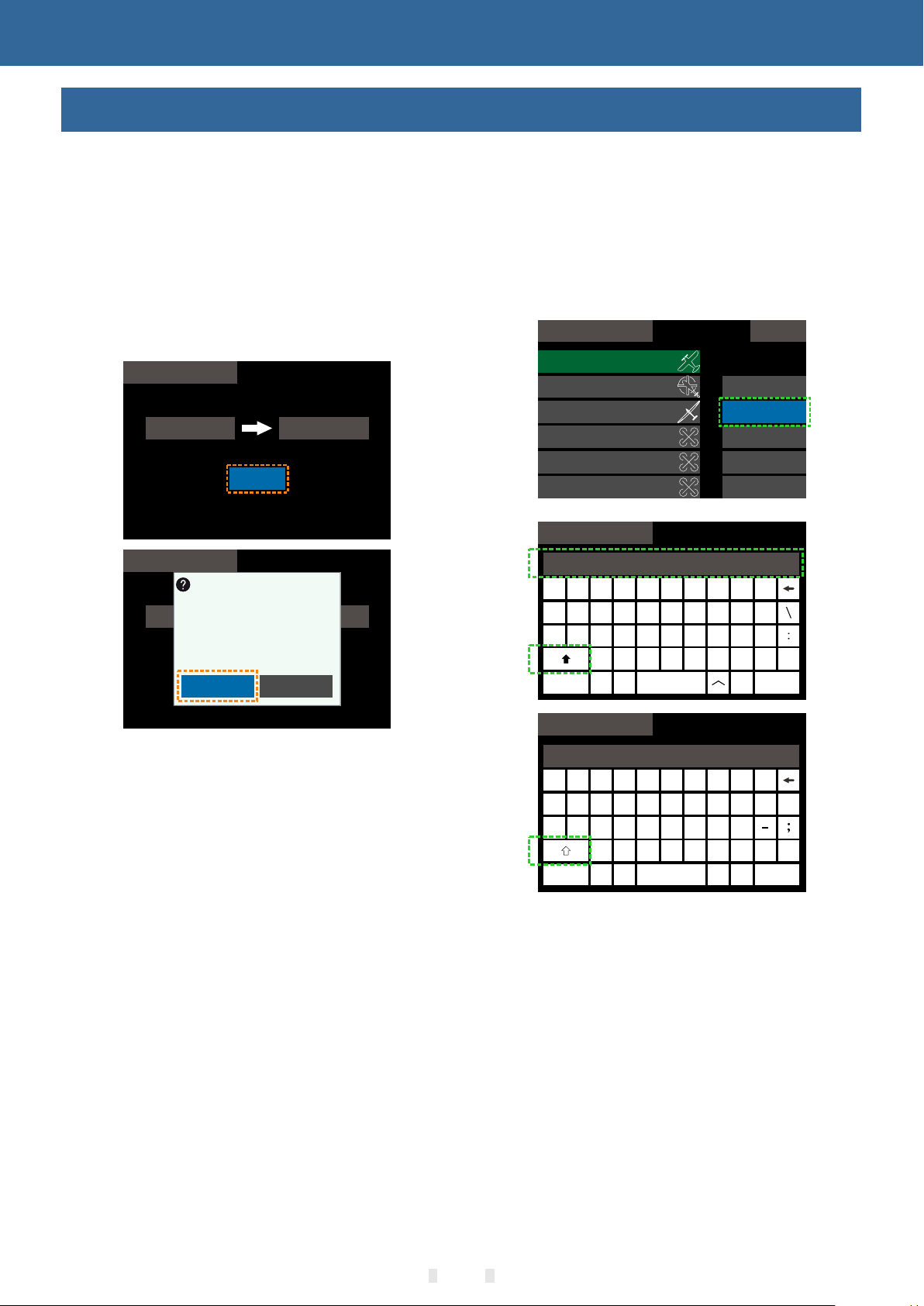
Popup prompt:
When the operation changes important
parameters, the selection box will pop up for
secondary confirmation. The default "No" is
selected.
Example:Model selection, interface replication
model operation!
After clicking the "Copy" button, the prompt
selection box pops up, select "Yes", then complete
the operation of copying the parameter of "Model 1"
to "Model 2".
Model Select
Source
Model 1
Model Select
Sure?
Source
Model 1
Copy
Yes
Object
Model 2
Object
Model 2
No
Keyboard
The keyboard is only used for naming function,
such as model renaming,
Flight condition naming, username setting.
The input keyboard is case sensitive and has
multiple symbols to choose from.
The input content above the interface could be
checked when naming.
1/7Model Select
Model 1
8
I
K
N
Select
Rename
Copy
Send
Receive
0
9
O
P
-
L
!
M
@
OK
"
Capital
Key
Model 2
Model 3
Model 4
Model 5
Model 6
Model Select
Model 12
2
Exit
W
S
3
E
D
Z
(
1
Q
A
7
6
4
5
R
F
X
Y
U
T
J
H
G
B
C
V
)
Warning popup
Starting up machine model function warning:
Turn the corresponding function switch to the
off position and enter into the system after the
warning disappeared.
Starting up machine low voltage alarm: select
"Yes" to continue the power on; select "No" to
shut down.
Receiver not connected alarm: Select "Back"
to close the alarm interface. (Some functions
need to enable the “Telemetry” function to be
used normally. After “ Telemetry” is turned on
and connected normally, the warning will not be
displayed.)
Stick calibration warning: Select "Back" to
close the alarm interface. (The receiver needs to
be disconnected during calibration!)
Shutdown alarm: Select "Back" to close the
warning interface and shutdown alarm.
Capital
Key
Model Select
Model 12
Exit
3
w
e
s
d
<
1 2
q
a
5
4
r
t
g
f
cx>z
7
6
y
h
v
8
9 0
u
j
k
b
p
o
i
mn
.
%
l
*
#
,
OK
015

LED
Status
Power
LED
Light on
Power on
Light off
Power off
Light flash
Power on alarm(Low voltage,power on/off warning)
RF
LED
Light off
Power Off/Student/Simulator/Mode
Light on
Normal communication,Trainer or normal mode
Light flash
Linking status
Basic Operation
Indicator Light of Transmitter
Power LED
Red
RF LED
Blue
Stick Adjustment
Stick head height adjustment:
1. Loosen the upper section head counterclockwise
2. Then twist the lower head to adjust the height
3. Twist the upper head clockwise to lock it
Stick feel and function adjustment
ET12 uses the newly developed four-bearing assembly to trim the feel!
Uncover the silicone sheet on the back and adjust the feel directly.
Note: Do not use excessive force or over twist the number of turns when adjusting the screw. Otherwise,
the structure assembly would be twisted off and the screw may fall off, resulting in irreversible damage.
Tooth adjustment
Smooth adjustment
Upper and lower elastic
adjustment position
Left and right elastic
adjustment position
Tooth adjustment
Smooth adjustment
Left and right elastic
adjustment position
Upper and lower elastic
adjustment position
016
①
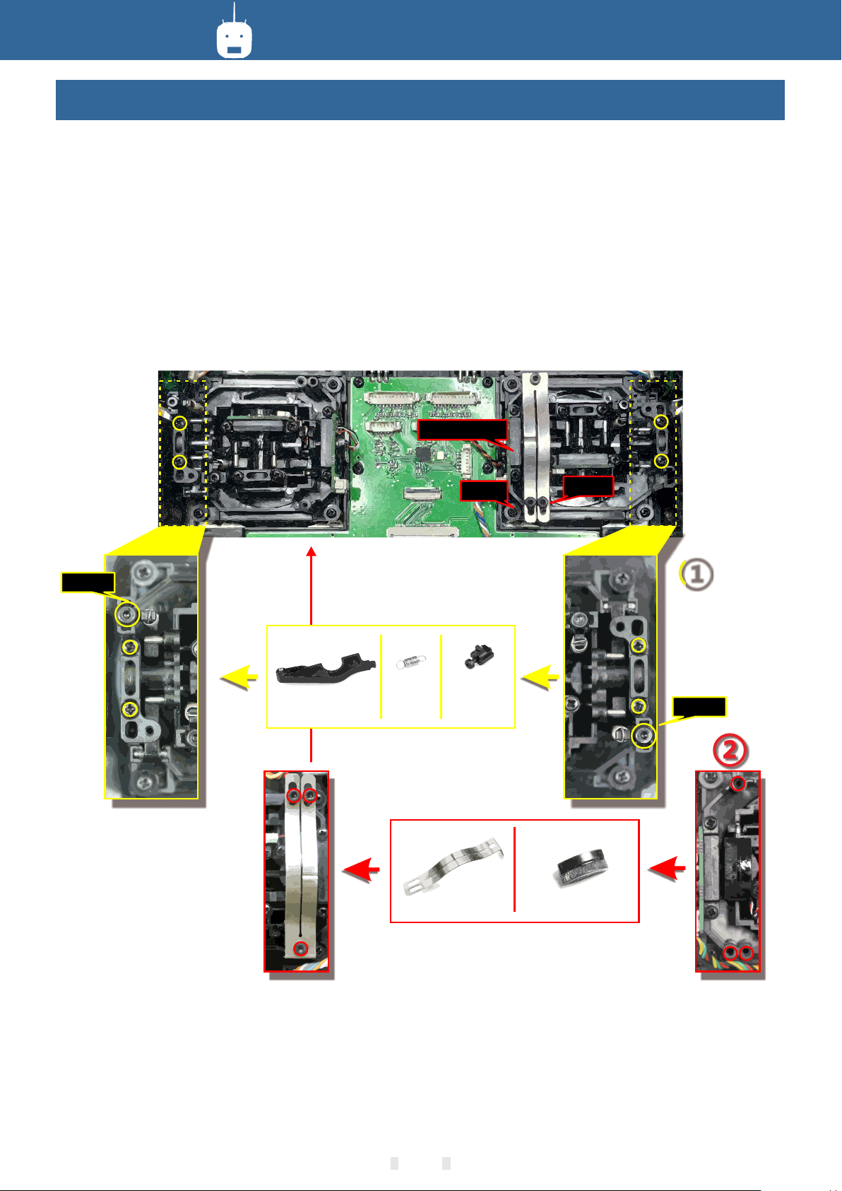
Basic Operation
Left and right stick mode replacement method
It is not recommended to replace the left and right sticks by yourself, otherwise the transmitter may be
damaged.
Required tools: 3 mm cross screwdriver, 1 .5 mm he x dr iv er
First open the transmitter housing and then follow the instructions show n be lo w:
1 Loosen the bearing housing s cr ew s (t he s cr ew s do n ot n ee d to b e fu ll y re tr ac te d) , th en r em ove th e
spring, bracket 7 and bracket 5 and tighten the scre ws ; th en r em ov e th e re mo ve d sp ring, bracket 7 and
bracket 5 in another assembly corres po nd in g po si ti on ( re move the bearing housing screw before
assembly),The tightness of the st
2 Remove the screw of the throttle reed, the throttle reed and the throttle sleeve, and install them in the
corresponding position o f th e othe r as se mb ly. According to your own habits, select the type of throttle
sliding (toothed and smooth) and adjust the screw (screw 1 o r The height of the screw 2) makes the
damping of the throttle conform to your own habits.
ick can be changed by adjusting the height of screw 3.
Throttle sleeve
Screw3
Screw 2
Bracket 5 Bracket 7
Spring
Screw 1
①
Screw3
Throttle reed Throttle sleeve
After the throttle structure is modified, turn on the machine, enter system setting → stick mode, select the
corresponding operatio n mo de , an d th en a dj us t th e st ic k af te r re pl ac in g th e left a nd r ig ht m od es! If you n eed
components such as bracket 5 (such as the pa rts need ed f or a ss em bl in g do ub le circuit structure!), you can
e-mail to WFLY overseas seller to order the spare parts at sales@wflysz.com
017

Mode
LED
Action
Status
Work
Purple
On
PWM normal work mode
Green
On
W.BUS normal work mode
Blue
On
PPM normal work mode
Red
On
No signal
Red
Slow flash
Low voltage
Orange
Slow flash
Linking
SET
Green
Slow flash
W.BUS mode
Blue
Slow flash
PPM mode
Purple
Slow flash
PWM mode
Ext.voltage
Basic Operation
Receiver Instructions
Receiver LED STATUS LIST
Link: Charge the receiver then press and hold
'SET' button for 3 seconds,wait for the link
instruction after the orange light slowly flashes.
PPM/W.BUS/PWM port modes select: Click and
hold the “SET” to charge, then enter into model
setting, slightly click the switcher mode, press and
hold to confirm.
USB port
External voltage detection port
Antenna
Keep straight
90°
Receiver mode switching: The receiver works in
"mode A" by default, and the receiver interface
output data according to the sticker serial number.
Switching the "mode" to the code will change the
interface output mode. You can use multiple
receivers to output more channels. More details,
please check [Linkage Settings - Link]
Receiver connection and installation
The working voltage of the receiver is 3.7-13V.
Each port can be used as the power input terminal.
Notice: pay attention to the positive and negative
polarity when connecting the power supply. Do not
use the power supply that exceeds the working
voltage of the receiver. Otherwise, the receiver will
be damaged!
The RF209S is the newest series of high
performance receiver with 9 PWM channels, 1
PPM/W.BUS channel (User defined), and 1 W.BUS2
channel (User defined).
In order to obtain optimal signal retrieval
performance, the two antennas are preferably
processed 90° to each other when installed, as
shown in the right diagram.
Mandatory
1Ω
W.BUS/PPM/PWM
W.BUS2/W.BUS/
PPM/PWM
The resistance is
connected to the negative pole
The red is
connected to the positive pole
External voltage detection port
Port polarity mark
PPM/PWM
8 7 6 543 2 1
Signal
Positive
9
Negative
1.If there is a metal conductor around the receiver antenna,the signal performance would be affected.
In this case, the antenna should be bypassed by the conductor, placed on both sides of the fuselage, and
it is better to make the antenna leak outside the model casing ! In this way, good signal reception can be
maintained regardless of the flight attitude.
2. When the antenna is installed. The unshielded end of the antenna should be as far away as possible
from the conductor materials such as metal and carbon fiber. The antenna cable avoids bending at large
angles. And the end core should be as straight as possible.
3. If the model body is covered with a conductive material such as carbon fiber or metal, the antenna
portion must be extended beyond the body. At the same time, do not stick too close to the conductive body
after the antenna is extended. In addition, the antenna should also be kept away from the fuel tank.
The receiver has an external battery detection interface, which can be used to view voltage information
such as ESC, battery, etc., and the transmitter can separately set alarm voltages for the receiver voltage
and external voltage. Pay attention to the positive and negative polarity when using the detection wire!
018
Basic Operation
Type Wing Flying wing Tail
1 AIL Normal
Channel AIL ELE THR RUD Gear Aux6 Aux6 Aux5 Aux4 Aux3 Aux2 Aux1
Control J1 J3 J2 J4 SG
Trim T1 T3 T2 T4
1 AIL V-Tail
Channel AIL ELE THR RUD Gear Aux6 Aux6 Aux5 Aux4 Aux3 Aux2 Aux1
Control J1 J3 J2 J4 SG
Trim T1 T3 T2 T4
1 AIL Ailevator
Channel AIL ELE THR RUD Gear Aux6 ELE2 Aux5 A ux4 Aux3 Aux2 Aux1
Control J1 J3 J2 J4 SG
Trim T1 T3 T2 T4
2 AIL Normal
Channel AIL ELE THR RUD Gear AIL2 Aux6 Aux5 Camber mix Aux3 Aux2 Aux1
Control J1 J3 J2 J4 SG LS
Trim T1 T3 T2 T4
2 AIL V-Tail
Channel AIL ELE THR RUD Gear AIL2 Aux6 Aux5 Camber mix Aux3 Aux2 Aux1
Control J1 J3 J2 J4 SG LS
Trim T1 T3 T2 T4
2 AIL Ailevator
Channel AIL ELE THR RUD Gear AIL2 ELE2 Aux5 Camber mix Aux3 Aux2 Aux1
Control J1 J3 J2 J4 SG LS
Trim T1 T3 T2 T4
2AIL+1FLP Normal
Channel AIL ELE THR RUD Gear FLP AIL2 A ux5 Camber mix A ux3 Aux2 Aux1
Control J1 J3 J2 J4 SG LD LS
Trim T1 T3 T2 T4
2AIL+1FLP V-Tail
Channel A IL ELE T HR RUD Ge ar FLP A IL2 Aux5 Camber mix Aux3 Aux2 Aux1
Control J1 J3 J2 J4 SG LD LS
Trim T1 T3 T2 T4
2AIL+1FLP Ailevator
Channel A IL ELE T HR RUD Ge ar FLP A IL2 ELE2 Camber mix Aux3 Aux2 Aux1
Control J1 J3 J2 J4 SG LD LS
Trim T1 T3 T2 T4
2AIL+2FLP Normal
Channel A IL ELE T HR RUD Ge ar AIL2 FLP FLP2 Camber mix Aux3 Aux2 Aux1
Control J1 J3 J2 J4 SG LD LS
Trim T1 T3 T2 T4
2AIL+2FLP V-Tail
Channel A IL ELE T HR RUD Ge ar AIL2 FLP FLP2 Camber mix Aux3 Aux2 Aux1
Control J1 J3 J2 J4 SG LD LS
Trim T1 T3 T2 T4
2AIL+2FLP Ailevator
Channel A IL ELE T HR RUD ELE2 AIL2 FLP FLP2 Camber mix Gear Aux2 Aux1
Control J1 J3 J2 J4 LD LS SG
Trim T1 T3 T2 T4
2AIL Normal
Channel A IL AIL2 THR RUD Gear Aux6 Aux5 Aux4 ELE Camber mix Aux2 Aux1
Control J1 J2 J4 SG J3 LS
Trim T1 T2 T4 T3
2AIL Winglet
Channel A IL AIL2 THR RUD Gear RUD2 Aux6 Aux5 ELE Camber mix Aux2 Aux1
Control J1 J2 J4 SG J3 LS
Trim T1 T2 T4 T3
2AIL+1FLP Norm al
Channel A IL AIL2 THR RUD Gear FLP AIL6 Aux5 ELE Camber mix Aux2 Aux1
Control J1 J2 J4 SG LD J3 LS
Trim T1 T2 T4 T3
2AIL+1FLP Winglet
Channel A IL AIL2 THR RUD Gear FLP RUD2 Aux5 ELE Camber mix Aux2 Aux1
Control J1 J2 J4 SG LD J3 LS
Trim T1 T2 T4 T3
2AIL+2FLP Norm al
Channel A IL AIL2 THR RUD Gear FLP Aux6 FLP2 ELE Camber mix Aux2 Aux1
Control J1 J2 J4 SG LD J3 LS
Trim T1 T2 T4 T3
2AIL+2FLP Winglet
Channel A IL AIL2 THR RUD Gear FLP RUD2 FLP2 ELE Camber mix Aux2 Aux1
Control J1 J2 J4 SG LD J3 LS
Trim T1 T2 T4 T3
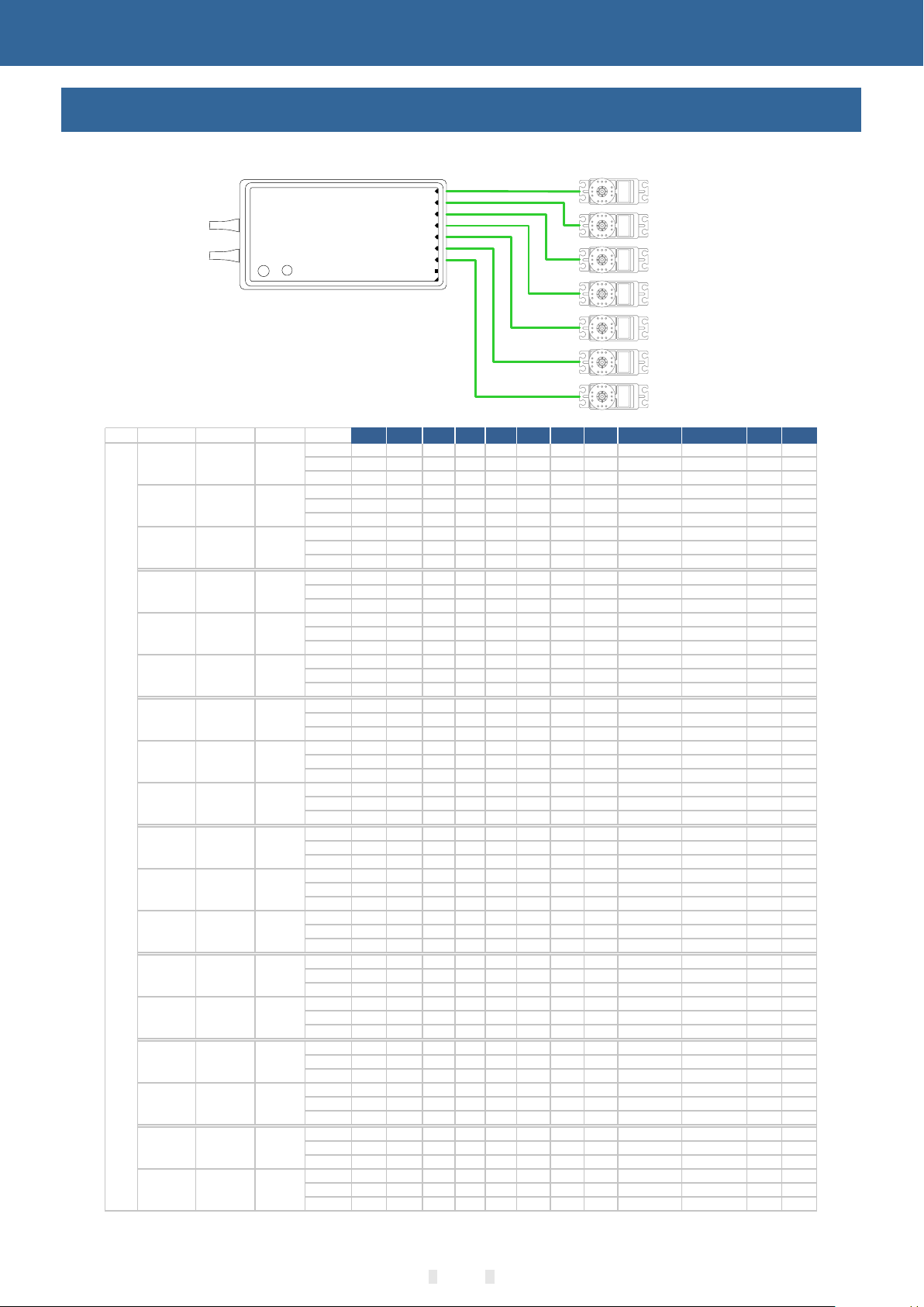
CH1 CH2 CH3 CH4 CH5 CH6 CH7 CH8 CH9 CH10 CH11 CH12
Receiver and servo connection example - Airplane
The figure below shows an example of airplane connection. Please use the actual wing type and
tail type for servo connection.
1 2 3 4 5 6 7 8 9
Servo connection position (Airplane)
The table below shows examples of the servo
connection positions for the different wing types
and tail types(system default settings).
CH1/Aileron
CH2/Elevator
CH3/Throttle
CH4/Rudder
CH5/Gear
CH6/FLP
CH7/Aileron2/Aux1
019

Basic Operation
Type Wing Flying wing Tail
1 AIL Normal
Channel AIL ELE Motor RU D Aux6 Aux6 Aux6 Aux5 Aux4 Aux3 Aux2 Aux1
Control J1 J3 SG J4
Trim T1 T3 T4
1 AIL V-Tail
Channel AIL ELE Motor RU D Aux6 Aux6 Aux6 Aux5 Aux4 Aux3 Aux2 Aux1
Control J1 J3 SG J4
Trim T1 T3 T4
1 AIL Ailevator
Channel AIL ELE Motor RU D Aux6 Aux6 ELE2 Aux5 Aux4 Aux3 Aux2 Aux1
Control J1 J3 SG J4
Trim T1 T3 T4
2AIL Normal
Channel AIL ELE Motor RU D Aux6 AIL2 Aux6 Aux5 Camber mix Butterfly Aux2 Aux1
Control J1 J3 SG J4 LS J2
Trim T1 T3 T4
2AIL V-Tail
Channel AIL ELE Motor RU D Aux6 AIL2 Aux6 Aux5 Camber mix Butterfly Aux2 Aux1
Control J1 J3 SG J4 LS J2
Trim T1 T3 T4
2AIL Ailevator
Channel AIL ELE Motor RU D Aux6 AIL2 ELE2 Aux5 Camber mix Butterfly Aux2 Aux1
Control J1 J3 SG J4 LS J2
Trim T1 T3 T4
2AIL+1FLP Normal
Channel AIL ELE Motor RU D Aux6 FLP AIL2 Aux5 Camber mix Butterfly Aux2 Aux1
Control J1 J3 SG J4 LS J2
Trim T1 T3 T4
2AIL+1FLP V-Tail
Channel AIL ELE Motor RU D Aux6 FLP AIL2 Aux5 Camber mix Butterfly Aux2 Aux1
Control J1 J3 SG J4 LS J2
Trim T1 T3 T4
2AIL+1FLP Ailevator
Channel AIL ELE Motor RU D Aux6 FLP AIL2 ELE2 Camber mix Butterfly Aux2 Aux1
Control J1 J3 SG J4 LS J2
Trim T1 T3 T4
2AIL+2FLP Normal
Channel AIL ELE Motor RU D Aux6 AIL2 FLP FLP2 Camber mix Butterfly Aux2 Aux1
Control J1 J3 SG J4 LS J2
Trim T1 T3 T4
2AIL+2FLP V-Tail
Channel AIL ELE Motor RU D Aux6 AIL2 FLP FLP2 Camber mix Butterfly Aux2 Aux1
Control J1 J3 SG J4 LS J2
Trim T1 T3 T4
2AIL+2FLP Ailevator
Channel AIL ELE Motor RU D ELE2 AIL2 FLP FLP2 Camber mix Butterfly Aux2 Aux1
Control J1 J3 SG J4 LS J2
Trim T1 T3 T4
2AIL Normal
Channel AIL AIL2 M otor R UD Aux5 Aux6 Aux4 Aux3 ELE Camber mix Aux2 Aux1
Control J1 SG J4 J3 LS
Trim T1 T4 T 3
2AIL Winglet
Channel AIL AIL2 M otor R UD Aux5 RUD2 Aux4 Aux3 ELE C amber mix Aux2 Aux1
Control J1 SG J4 J3 LS
Trim T1 T4 T 3
2AIL+1FLP Normal
Channel AIL AIL2 M otor R UD Aux5 FLP Aux6 Aux3 ELE Camber mix Butterfly Aux1
Control J1 SG J4 J3 LS J2
Trim T1 T4 T 3
2AIL+1FLP Winglet
Channel AIL AIL2 M otor R UD Aux5 FLP RUD2 Aux3 ELE Camber mix Butterfly Aux1
Control J1 SG J4 J3 LS J2
Trim T1 T4 T 3
2AIL+2FLP Normal
Channel AIL AIL2 M otor R UD Aux5 FLP Aux6 FLP2 ELE Camber mix Butterfly Aux1
Control J1 SG J4 J3 LS J2
Trim T1 T4 T 3
2AIL+2FLP Winglet
Channel AIL AIL2 M otor R UD Aux5 FLP RUD2 FLP2 ELE Camber mix Butterfly Aux1
Control J1 SG J4 J3 LS J2
Trim T1 T4 T 3
CH1 C H2 CH3 CH4 CH5 CH6 CH7 CH8 CH 9 CH10 CH11 CH12
Receiver and servo connection example - Glider
The figure below shows an example of glider connection. Please use the actual wing type and tail type for
servo connection.
1 2 3 4 5 6 7 8 9
CH1/Aileron
CH2/Elevator
CH3/Throttle
CH4/Rudder
Servo connection position (Glider)
The table below shows examples of the servo
connection positions for the different wing types
and tail types.
CH5/Gear
CH6/FLP
CH7/Aileron2/Aux1
020

Basic Operation
T yp e S wash
H
e
l
i
c
o
p
t
e
r
H-1
Ch anne l A IL EL E T HR R UD G yro P IT G overn or N e e dl e G yro2 G yro3 A u x2 A u x1
Co ntro l J1 J3 J2 J4 J2 LS
T rim T1 T 3 T 2 T 4
HR3
Ch anne l A IL EL E T HR R UD G yro P IT G overn or N e e dl e G yro2 G yro3 A u x2 A u x1
Co ntro l J1 J3 J2 J4 J2 LS
T rim T1 T 3 T 2 T 4
H-3
Ch anne l A IL EL E T HR R UD G yro P IT G overn or N e e dl e G yro2 G yro3 A u x2 A u x1
Co ntro l J1 J3 J2 J4 J2 LS
T rim T1 T 3 T 2 T 4
HE3
Ch anne l A IL EL E T HR R UD G yro P IT G overn or N e e dl e G yro2 G yro3 A u x2 A u x1
Co ntro l J1 J3 J2 J4 J2 LS
T rim T1 T 3 T 2 T 4
HN 3
Ch anne l A IL EL E T HR R UD G yro P IT G overn or N e e dl e G yro2 G yro3 A u x2 A u x1
Co ntro l J1 J3 J2 J4 J2 LS
T rim T1 T 3 T 2 T 4
H4X
Ch anne l A IL EL E T HR R UD G yro P IT G overn or ELE2 Gyro 2 G yro 3 A u x2 A ux 1
Co ntro l J1 J3 J2 J4 J2
T rim T1 T 3 T 2 T 4
H-4
Ch anne l A IL EL E T HR R UD G yro P IT G overn or ELE2 Gyro 2 G yro 3 A u x2 A ux 1
Co ntro l J1 J3 J2 J4 J2
T rim T1 T 3 T 2 T 4
CH 1 C H2 C H3 CH 4 CH 5 C H6 CH 7 CH 8 CH 9 CH1 0 CH 11 CH 12
Receiver and servo connection example - Helicopter
The figure below shows an example of helicopter connection. Please use the actual wing type and tail
type for servo connection.
1 2 3 4 5 6 7 8 9
CH1/Aileron
CH2/Elevator
CH3/Throttle
CH4/Rudder
GRO
CH5/Gyro
CH6/Pitch
CH7/Aux/Governor
Servo connection position (Helicopter)
The table below shows examples of the servo connection positions for different swashes.
Swash Types
PIT
Normal
H-1
AIL
HN3(120°)
ELE
PIT
PIT
H-4
AIL
ELE
ELE
AIL
ELE 2
ELE
PIT
HE3H-3
H-4X
ELE
ELE 2
021
PITAIL
AIL
PIT
HR3(120°)
AIL
ELE

Basic Operation
Type
M ultic opter
C hannel A IL ELE T HR R UD Fl ig ht mode 1 P&T PITC H P&T Around C amera r ecor d Aux4 Aux3 Aux2 A ux1
C ontrol J1 J2 J3 J4 VL VR SH
Tr im T1 T 2 T3 T4
C H1 C H2 C H3 C H4 CH 5 CH 6 C H7 C H8 C H9 C H10 C H11 C H12
Receiver and servo connection example - Multicopter
The figure below shows the four-rotor multicopter. Please refer to the model manual for specific
applications. Motor,electronic speed controller, flight controller, battery, etc. are sold separately.
Use 5CH-9CH when using accessories such
as camera shutters. Use a W.BUS interface or
dual receiver when the channel is insufficient.
1 2 3 4 5 6 7 8 9
Ch1 Ailero n
Ch2 Elev ato r
Ch3 Thro ttle
Ch4 Rudd er
Ch5
Multic opt er
fli ght c ont roll er
Battery
This figure is for illustrative purposes only. Link amplification also changes depending on the
multicopter collective and the flight controller. Please connect according to the instruction
manual of the multicopter kit to be used.
Servo connection position (Multicopter)
022

Basic Operation
Basic setting sequence of airplane and glider
1. Call of the model
The ET12 transmitter has 30 built-in models from
the factory, and you can use the [Model Selection]
under [General Menu] to call up the existing model.
The Rename feature makes it easy to make a
selection call to a model whose name has already
been set.
The name of the model currently in use is
displayed on the home page. Before flying and
changing the parameter settings, be sure to
determine if the correct model is selected.
When a new model is added, please select [Type
Selecting] under [General Menu] according to the
model used. If a new receiver is used, the receiver's
code operation is also required ([Linkage Setting][Link]
2. Model type selection
Use the [Type Selecting] function under [General
Menu] to select the model type, wing type, and tail
type that match the model airplane.
For example, the left and right azimuth servos
can be selected from the main wing type by
selecting "2 ailerons" and adjusting the two servos
in [Sub-Trim] and [End Point] respectively.
3. The fuselage control part connect
Install the ailerons, elevators, throttles, rudders,
etc. as required by the model aircraft product
specification. For the connection method, refer to
the "Receiver and Servo Connection Example Airplane" (P19) and the "Receiver and Servo
Connection Example - Glider" (P20) section.
Note: ET12 transmitters have different channel
assignments depending on the model type, so
please pay special attention (in the [General Menu]
option under General Menu], you can check the
allocation of each channel).
● If the direction of the actual connection is
opposite to the direction you want, you can use
[Reverse Setting] under [General Menu] to adjust
the direction.
● Install the throttle section to ensure that the
carburetor/electronic governor can be fully open or
fully closed.
● Use the [End Point] under [Function] to adjust
the end point and rotation angle of each rudder
surface, and use the [Sub-trim] function and the
[End Point] function to make fine adjustments. In
order to protect the connecting rod, the stroke limit
position can be set in the [Rudder Angle Setting]
function item. [End Point] function item can adjust
the up and down or left and right movement amount
of each rudder surface And limit.
4. Throttle Cut Setting (Airplane)
The [Throttle Cut] function allows us to turn off the
engine by only one switch without affecting the
throttle trim position (after idle adjustment).
* When the [Throttle Cut] function is activated,
the engine flame out position will be fixed. If the
throttle cut switch is not required, use the [ Idle
Down] setting function below.
Please use the [Throttle Cut] function option
under [Model Menu] to set. After the flame out
function is activated and the corresponding switch
is selected, the throttle position will be adjusted
until the carburetor is fully closed. For safety
reasons, the activation position of the throttle lever
position corresponding to the throttle stop function
can be set separately.
5. Idle Down setting (Airplane)
The [Idle Down] function option is located under
[Model Menu]. * When the [Throttle Cut] function is
operated, the [Idle Down] function will not be
activated. Without changing the throttle trim
position, using a switch can reduce the idle speed of
the airplane.
After activating this function and selecting a
switch, you can adjust the desired number of idling
revolutions. For safety reasons, this function is only
activated when the throttle lever is in the lower
position (approximately 1 / 3 of the total stroke).
6. Dual Rate Settings
[Dual Rate] function is to match the feeling of
control and adjust the rudder angle, which makes
the control more convenient. The basic operating
range of the steering gear is set in the [End Point]
function under [General Menu], and the steering
feel is adjusted by the [Dual Rate] ratio function of
the [General Menu]. In addition, after setting the
rudder angle ratio, it can also be switched by the
switch or flight condition, and the flight action can be
used to call up the set rudder angle.
7. Air brake
[Air Brake] function is used when landing, etc.,
when the sliding angle is large but the speed is no
need to be increased. This function can only be
used on models with [General Menu] - [Model
Selecting] and "2 Ailerons" on the wing. * Normally,
the left and right ailerons are simultaneously set to
the upward movement, and the pitch of the nose can
be corrected by the elevator mixing when the
function is started.
8. Flight conditions
The factory default setting assigns only one flight
condition per model. Only one flight condition can
support basic flight without barriers, but if you are in
a competitive situation such as a game, you need
more detailed settings. Through the [Flight
Condition] function in [Model Menu], you can select
the required flight conditions more effectively. It can
also be set for the switch of the condition switch and
the name of the condition. After the flight condition
setting is completed, the switch needs to be
operated, and the condition name displayed on the
interface is confirmed.
023

Basic Operation
Basic setting sequence of the helicopter
1. Model addition and invocation
Please refer to the first part of the previous
section "Basic Operation - Basic Settings of Fixed
Wings and Gliders".
2. Model type and swash plate type selection
If you have already set up a model, use the
[Model Type] selection interface to select the
helicopter in [Model Function], and then select the
swash type according to the model.
3. Flight conditions setting
The default setting contains the common mode
(default naming) conditions.
There are 5 conditions that have been set.
● Normal
● Idle 1 (SE)
● Idle 2 (SE)
● Idle 3 (SF)
● Hold
*This switch is not set in the default settings
Examples of common flight conditions settings:
● Normal: (for default settings, switch off) usually
starting, hanging
Use when stopped.
● Idle 1: (Starting when the SE switch is in the
middle position) is usually used to lose
Speed reverse, muscles and other Idles.
● Idle 2: (Starting when the SE switch is forward)
is usually used for roll.
●Lock: (usually set to start when the SG switch is
forward) Usually in self
Used in the spin state.
The priority of these operating conditions is
1,Hold(Throttle Hold)
2,Idle 2
3,Idle 1
4,Normal
5,The lock mode has the highest priority
4. Body control connecting rod installation
Install the throttle, tail rotor, aileron, elevator,
pitch, etc. as required by the model helicopter
product specification. The connection method can
be referred to the "Receiver and Servo Link
Example - Helicopter" (P21) section.* In the
[Function] option under [General Menu], you can
check the allocation of each channel.
● If the direction of the actual connection is
opposite to the direction you want, you can use
[Servo Reverse] under [General Menu] to adjust the
direction. In addition to the H-1 mode, you can also
change the direction using the [Swash] function.
● Set the direction of the gyroscope (this is the
"Gyro" function)
● The throttle section should be installed to
ensure that the carburetor can be completely closed
when Trim is fully closed.
● Use the [End Point] under [General Menu] to
adjust the ravel amount and rotation angle of each
rudder surface, and use the [Sub-trim] function and
the [End Point] function to make fine adjustments. In
order to protect the connecting rod, the travel limit
position can be set in the [End Point] function item.
The [End Point] function item can adjust the up and
down or left and right movement amount and limit of
each rudder surface.
The swash calibration (except H-1 mode) can
calibrate the swash motion by the correction mixing
control of the [swash] function. This function is
required when the pitch, aileron,and elevator
operations cause the swash to deviate from the
correct elbow. In addition,the pitch of the link at the
low point and the high point can also be calibrated,
which is used to ensure the horizontal state of the
swash in the full stroke range.
5.Throttle Curve,Pitch Curve setting
Bring up [Throttle Curve] or [Pitch Curve] from the
[Model Menu] and set the curve for various flight
conditions.
+1 5 0
+1 0 0
+5 0
-5 0
-1 0 0
-1 5 0
+0 %
PO S
0
RA T E
+0 %
<Setting example>
Use the flight condition selection switch to bring
up the throttle curve for each flight condition.
Throttle curve setting example is as follows:
● Throttle curve (General)
The normal curve uses a normal line type, and the
basic pitch curve is set near the hover point (50% of
the stick). This curve is usually adjusted with the
pitch to ensure that the engine speed is uniform and
the up/down action is easy to handle.
● Throttle curve (Idle 1)
This setting is to maintain stick rotate when the
throttle lever is in the low position.
● Throttle curve (Idle 2)
This setting maintains rotation when the throttle
lever is in the low position and there is no pitch.
●Setting when the condition is locked
Note: The throttle lock curve is used for the spin
landing action. Please confirm the ratio of the
lowest position of throttle control stick is 0% (this is
the initial setting).
Examples of pitch curve settings are as
follows:
The pitch curve can be called up under each
condition using the flight condition selection switch.
●Pitch curve (General)
In the pitch curve, the hover pitch is usually set to
approximately +5° ~ +6°. Under normal
circumstances, the throttle stick is hovered at 50%
position as the standard.* Stable hovering is also
related to throttle curve setting. It is easier to
achieve stable hover by using throttle curve
adjustment and pitch curve adjustment.
●Pitch curve (Idle 1)The pitch curve of the effect 1
is usually used for air flight, and is generally set to 7°~+9°.
●Pitch curve (Idle 2)The setting of the high point
bit 1 is slightly lower, and the value is set to about
+8°.
●Pitch curve (HOLD)In the throttle lock and spin
drop conditions, the pitch should be set to the
024

17%
Basic Operation
Basic setting sequence of the helicopter
maximum in both the positive and negative pitch
directions. For example, from -7 to +12°
6. Throttle Hold Setting
In the model menu, call the [Throttle Hold]
function setting interface, and use the [Fly
Condition] switch to switch to the throttle lock
condition interface.
Lock position setting: This function is used to
set the working position (extinguish or idle
position) of the servo under the throttle lock state.
Throttle hold
Status
Switch
Hold pos.
Speed
INH
--
0
7. The Swash Mixing Controls the
Interaction of the Ailerons, Elevators and
Paddles
Through the [Swash Mixing] under [Model
Menu], the mixing ratio of each operation of the
aileron, elevator, and pitch can be adjusted to
ensure that the swash is corrected under each
condition.
10. Throttle Setting
At the end of the flight, there is no need to
change the position of the throttle trim, just turn
off the engine by simply turning a flameout switch.
Set in the [Throttle Cut] function of [Model
Menu]. Set the throttle lever to idle speed and
adjust the rotation position of the flameextinguishing servo until the damper can be
closed and the movement is unimpeded.
*The throttle trigger position can be set
separately.
Throttle cut
Status
Switch
Cut pos.
Throttle
INH
--
17%
17%
8. Throttle Mixing Setting
The swash aileron and elevator action will
cause the engine speed to decrease. This
phenomenon can be compensated by [Throttle
Mixing] under [Model Menu]. In addition, the
clockwise and counterclockwise torque changes
can be compensated for when the body rotates.
9. Gyro Sensitivity Adjustment and Mode
Switching
In the [Gyro] mixing function under
[ModelMenu], you can adjust the gyro sensitivity
or mode switching for each condition or switch
position.
● Normal (hover flight): The gyroscope is the
most sensitive.
● Idle 1 / Idle 2 / Throttle Hold: Gyro sensitivity
is minimal.
Gyro
Gyro
Mode
Position
Status
Type
Gyro1
Condition
Condition1
INH
AVCS
1/2
Gyro
Rate
Tun ing
AVCS100%
--
0%
2/2
0%
025

System Setting
Trainer
Interface Path: WFLY → [System Setting] → [Trainer]
Trainers can assist students in learning flight skills and improving flight levels based on their flight
experience and operational level. A special trainer line (sold separately) is required between the trainer
and the trainer to connect. The trainer must turn on the trainer mode before the trainer can be operated.
When the trainer switch is turned off, it will return to the trainer transmitter to control the flight. When the
student machine flight is dangerous or the deviation is too large,the trainer can be switched immediately to
ensure safety.
When using the WFT08/09 as a trainer, please purchase a universal analog patch cord, 3.5mm male to
male audio cable. (The coaching line and audio cable need to be purchased separately. Two cores and
three cores are available.)
Tra iner
Mode
Teach SW
CHmode
CH
Aileron
1
Elevator
2
*The following trainer functions take the same model as an example.
Tra iner
--
12CH
Status
ON
ON
1/2
Mode: Normal, Trainer, Simulator, Student
- Normal: Default mode (non-"Trainer", "Student" mode
using trainer function may cause malfunctions! )
- Trainer: Control transmitter;
- Simulator: When the flight is practiced through the
computer-side simulator, the RF is turned off, reducing
power consumption.To extend the working hours of the
transmitter;
-Students: Turn off RF transmission,only the trainer turn on
theTeach switch can trainer channel could be controlled!
(Example: The trainer model has only three channels:
aileron, direction and gyro, so the student can only control
these three channels when the coach turn on the trainer
switch. )
Trainer Switch: Default [--]
Channel Mode: default is "12 channel" setting; "8 channel
mode" is compatible with WFLY training function of the
"WFT" series products. The trainer ’s two ET12s need to be
set up to the same mode.
Status: Each channel status switch of trainer. Turn on,
students can be controlled; off, students Uncontrollable
Trainer Setting:
Trainer switch → Trainer, channel mode → 12
channels, channel status → Turn on with demand
(status is the same as the student machine).
* The channel defaults to full on, and the visual
model and actual application are adjusted.
Be sure to check that all channels of the
trainer and the student can be operated
NOTICE
normally before flying. Be sure to insert
the interface of the trainer line to avoid
loosening.
Student Setting:
Trainer switch → student, channel mode → 12
channels, channel status → Turn on with demand
(status is the same as the trainer).
* The channel defaults to full on, and the visual
model and actual application are adjusted.
026

System Setting
Display
Interface Path: WFLY → [System Setting] → [Display]
Adjust the brightness of the display backlight, the shutdown time, and the lock screen time to
adapt to different environments and energy saving.
Display
Backlight max
Backlight min
Tim e
Auto off time
Auto lock
Parameter Value Setting(taking the maximum backlight as an example):
Click the “Backlight max” value box and click the parameter adjustment buttons [▼], [▲] according to the
visual effect.
The maximum backlight, the default is 10, the range: 1~20, the setting value can't be lower than the
minimum backlight setting value.
The minimum backlight, the default is 10, the range: 1~20, the setting value can't be higher than the
maximum backlight setting value.
Backlight time, default 30 seconds, 15 seconds, 30 seconds, 1 minute, 2 minutes, 5 minutes, 10 minutes,
always bright.
Auto power off time, default off, 30 minutes, 40, 50, 60 minutes, off.
Automatic lock screen time, default off, 15 seconds, 30 seconds, 1 minute, 2 minutes, 5 minutes, 10
minutes, off.
10
10
30Sec
Never
Never
The backlight switches to the "Backlight max" value!
The darkest brightness value of normal standby.
It means that no button and touch screen operation time is
detected after setting value.
The transmitter is turned off after no operation.
Lock screen after when the touch screen has no operation.
WARNING
High brightness display will increase
the energy consumption of the
transmitter, which will affect the
working time of the transmitter. Please
pay attention to setting the transmitter
voltage alarm. Pay attention to the
battery level and avoid low battry
operation of the transmitter.
027

Q
W
E
R
T
Y
U
I
O
P
1
2
3
4
5
6
7
8
9
0
OK
@
Exit
-
"
!
M
N
B
V
C
X
)
Z
(
A
S
D
FGH
J
K
L
q
w
e
r
t
y
u
i
o
p
1
2
3
4
5
6
7
8
9
0
OK
,
.
Exit
;
-
*
#
m
n
b
v
c
x
>
z
<
a
s
d
f
g
h
j
k
l
System Setting
User Name
Interface path: WFLY → [System Setting] → [User Name]
The user defied name is composed of up to 9 characters and supports English character input, which can
be displayed on the standby interface.
SIM
ET12
00:00.0
Receiver
00:00.0
-50 0
User Name
5.0V
12.0VExternal
Condition1
T5
T6
+25
0 +100 0
Home2
T4
+10 00
00:00.0
12.9V
RX
T3
T2 T1
User name
Model 1
-50 0
User Name
User N a me
User Name
*The keyboard can only be operated by touch screen.
*The naming needs to be confirmed before the modification can be saved.
Model select
Model 12
Model select
Model 12
Case switch key
%
Confirmation key
(Save key)
Turn off keyboard
Unname
028

System Setting
Sound
Interface path: WFLY → [System Setting] → [Sound]
The sound helps the flight process to notice various anomalies or planned audible prompts.
The sound is associated with the model, and the prompt tone can be set according to the requirements of
each model.
Sound
Warn in
Telemetry
Button
Other
Tri m
timer
WARNING
80
80
50
50
80 Voice
80 Voice
Volume
To ensure safe operation, be sure to
turn on the Sound!
Voice
029

System Setting
Warning
Interface path: WFLY → [System Setting] → [Warning]
After the function is turned on,there will a corresponding detection reminder when the power-
on detection .
Under setting conditions,there will be an interface, sound, and vibration prompts when the
transmitter detection is in effect. Vibration tips can be set individually.
Warn ing
飞行条件
Condition
THR cut
Idle down
THR posi.
Airbrake
Alarm Vibrator
ACT
ACT
ACT
ACT
ACT
INH
INH
INH
INH
INH
Parameters Setting (Enable the "Flight Condition" alarm with vibration function as an example):
Click the “Alarm button” on the right side of “Flight Condition” and the function will switch to “ACT”; click
the “Vibraor button” on the far right to switch to “ACT”.
*Vibrator function may affect the focus of individual user operations,so the default status is inhibit.
Different models will have different warning content
Helicopter: flight condition, throttle cut,idle down, throttle position, throttle hold.
Airplane: flight condition, throttle cut,idle down, throttle position,air brake, motor, throttle hold.
Glider: flight condition, throttle cut,idle down, throttle position,motor, throttle hold.
Multicopter: flight condition, throttle cut, throttle position, throttle hold.
030
 Loading...