

Wfly ET07 Instruction Manual
1
Shezhen WFLY Technology Development Co.,Ld
10 Channels Digital Proportional R/C System
ET07
Mor e produ ct info rmati on,
ple ase fol low the W eC hat o ffici al
acc ount ab ove
Instruction Manual
V1.04

2
Thank y ou for using WFLY pro ducts!
● Pleas e read this prod uct manua l carefully be fore usin g this product !
● Pleas e use this produ ct proper ly!
The R/C m odel is not a toy, for safety, please do n ot fly in cro wded places!

3
Funct ion Catalogu e
Pleas e read the follo wing inst ructions car efully befor e use to ensu re safely use of t he produc t
6
7
8
8
8
9
9
10
11
11
12
13
14
14
15
16
17
17
18
19
20
21
22
Safet y Caution
Symbo ls Definitio n
Flyin g Notices
Batte ry
Trainer
USB Int erface
Befor e Use
Produ ct Features
Basic C onfigurati on
Each Pa rts Name Of Trans mitter
Switc h Configurat ion And Type s
The Trav el Of Antenna Dir ection Adj ustment
Basic O peration
Home In terface Oper ation
Touch Scr een Operatio n
Indic ator Light Of Tra nsmitte r
Stick Ad just Instruc tion
Stick Ad justment
Recei ver Instruct ions
Recei ver And Servo Lin k Example
-airp lane
-glid er
-heli copter
-mult icopter
Model s Basic Settin g Sequenc e
-airp lane and glide r
-heli copter

4
Funct ion Catalogu e
Save mul tiple sets o f set paramete rs and swit ch freely when n eeded
Name a gr oup of model par ameters
Selec t helicopter, airplan e or multicopt er
Copy on e group of model p aramete rs to another gr oup of mode l parameters
Reset a g roup of model pa rameter s to initial val ue
Set low b attery alarm p oint
On/Off sound
Adjus t backlight br ightnes s, light time
Set tra iner or simula tor funct ion
Input l etter or numbe r,as a user na me
Modif y the screen bac k colour
Calib rate the neutr al point of a ilerons, ele vations , accelerato rs, direc tional
chann el rocker and th e positio n of the upper, low er, left and r ight endpoin ts
Selec t suitable ope ration st ick mode
Selec t English or Chi nese inte rface langua ge
Reset a ll parameter s of transm itter
Displ ay the unit sett ing
Calib rate the panel s creen
Transmitte r system in formation
24
24
25
26
26
27
27
27
28
29
29
29
30
30
30
30
31
31
Syste m Setting
Model S elect
Model N ame
Model Type
Model C opy
Model R eset
Low Volt age
Sound
Backl ight
Trainer/Si mulator
User Na me
Back Co lor
Calib ration
Stick M ode
Langu age
Facto ry Reset
Telemet ry Unit
Scree n Cal
Infor mation
32
33
33
34
35
36
36
36
Linka ge Setting
Link St ep
Telemet ry
Servo F requency
Range C heck
Fail Sa fe
W.BUS Se rvo
PPM/W. BUS
Rx Port S etting
Transmitte r and recei ver link
Displ ay the set senso r data
The ser vo working fre quency
Reduc e the power to rem ote contr ol range check
When th e receiver los t the signa l, it automati cally loa ds the preset sc heme
for the b ody action saf ety prote ction
Set ser vo
Switc h the output mod e of receiv er
Set the o utput channe l of receiv er port
37
37
37
38
39
40
40
40
40
41
41
Gener al Menu
Monit or
Servo R everse
Sub-Trim
Timer
Dual Ra te
End Poi nt
Trim Step
Aux Cha nnel
Chann el Delay
Progr am Mix1-3
Curve M ix1-2
Monit oring and disp laying th e output statu s of each cha nnel
Set eac h channel reve rse to matc h the neutral po int of each m odel channel
Adjus t the netrual po int of each c hannel
Set fly ing alarm time t o help remi nd battery or fu el capaci ty
Adjus t the channel ou tput valu e to adapt the dua l rate of eac h model channe l
Chann el end point and l imit posi tion
Set the t rimming step v alue of eac h channel
Custo mize the switc h of 5-10 cha nnel
Set the d elay value
Mixin g the output of 2 ra ndom chan nels
Mixin g the 2 ramdon cha nnels of cu rve controll ed

5
Funct ion Catalogu e
42
42
43
43
43
44
44
45
45
46
47
48
48
Model M enu\Airpla ne
Throt tle Hold
AIL Diff erential
Ailer on 2
Fly Mod e
Throt tle Cut
Throt tle Curve
Flap Tri m
ELE to Fl ap
Flape ron
Elevo n
Airbr ake
Ailva tor
V-Tail
Hold th e throttle out put statu s
Adjus t the diff erential of AIL 1 and AIL2
Assig n another AIL chann el
Motio n mode assignm ent
To make ins tant throttl e cut after f lying
Adjus t the linear rel ation of th rottle
Adjus t flap end point ,change f lap channel se peratel y,contr ol mix will sync hronize
Adjus t elevator and f lap for one w ay mixed contr ol
Adjus t the step of flap a nd ailero n
Combi ned aileron an d elevato r mixed contro l
Adjus t ELE and AIL one way mix
Adjus t elevator and r udder mix ed control
Model M enu/Helico pter
Throt tle Hold
Throt tle Curve
Swash
Fly Mod e
Throt tle Cut
Pitch C urve
Idle Do wn
Gover nor
Gyro
Hold th e throttle out put statu s
Adjus t the liner rela tion of thr ottle
Selec t swash types an d set swash p arameters
Motio n mode assignm ent
To make ins tant throttl e cut after f lying
Adjus t the pitch outp ut liner re lation
Idle sp eed control
Gover nor special ad justmen t
Adjus t the gyro sensi tivity un der each different fly m ode
49
49
50
50
51
51
52
52
52
53
53
54
54
Model M enu/Multic opter
Switc h Program
Throt tle Hold
Fly Mod e
Throt tle Curve
Hold th e output statu s of thrott le
Motio n mode assignm ent
Adjus t the throttle o utput lin er relation
6
Safety Caution
Symbols Definition
If with out a proper ope ration,it ma y cause
dange rous acciden t or seriou sly injury or ma y
even ca use death.
If with out a proper ope ration,it ma y cause
dange rous acciden t or seriou sly injury or ma y
even ca use death,an d it may caus e slight hurt
or prob ability caus e bodily injur e!
If with out a proper ope ration,it ma y cause
less po ssibility to s erious hu rt,but it may
cause h urt or bodily in jure.
Pay spe cial attenti on to the saf ety informat ion of the fo llowing symb ols
WARNING
DANGER
NOTICE
Prohi bitions
Compu lsory Items
7
Flying Notices
To ensure t he safety of you rself and o thers,
pleas e observe the fo llowing p recautions :
Charg e the batterie s! Check tr ansmitter an d
recei ver battery le vels and al ways recharg e the
batte ries before ea ch flying s ession. A low batt ery
will so on die potenti ally, cau sing loss o f control and
a crash . When you begin y our flyin g session, res et
your ET 07 built-in ti mer, and dur ing the sessio n pay
atten tion to the dura tion of usa ge.
Be care ful when flyin g near power li ne, High
st ructures or com municatio n faci litie s, as the re
may be ra dio int erfe rence aroun d.
Begin ners should pa y particu lar attentio n to the
follo wing safety pr ecautio ns! Please rea d careful ly!
It is for bidden to fly wh en in poor co ndition such
as fati gue and drunke nness.
It is for bidden to fly in b ad weathe r such as rain
and gal e.
It is for bidden to fly ne ar high vol tage lines,
commu nication bas e station s and places whe re
peopl e gather or acti vate.
It is for bidden to fly in a irports a nd other place s
where f ly is forbidde n.
Befor e flying, test t he equipm ent, check whe ther
the tra nsceiver sys tem and the a ircraft are no rmal;
When fl ying, make the i nterfac e of transmitt er in
the ini tial interfa ce for prev enting the cha nge of
param eters by mista ke;
After f lying, turn off the rece iver prim arily and
then tu rn off the t ransmitter f or protec ting people
from th e fail-safe fu nction.
More de bugging, mor e testing , less loss, les s
damag e!
Power on and off sequency of tran smit ter
and receiver!
Power on step:
Fi rstly turn on t he tra nsmitter (e nsuri ng the
mi nimum throttle po sitio n),
Se condl y Turn on the re ceiver.
Power off:
Fi rstly turn off t he rece iver,S econdly tur n off the
transmitte r.
Trans mitt er and re ceiver low voltag e may cause
fail safe dang er.
No tice: The transmi tter will display th e warn ing
in terface, please pay att entio n to the transmitte r
prompt ! Improperly operation m ay cau se acci dent
in jury to user.
Discl aimer & Warning:
User sh ould be respon sible for a ny consequen ces
cause d by using the pro duct. WFLY shall no t be
liabl e for any direct ly or indir ectly damage , injury
and any l egal liabili ty,User s hall comp ly with all
guide lines includ ing but not l imited to this
docum ent. Please fo llow the lo cal laws and
regul ations for reg ular flig ht activitie s. Do not use
this pr oduct to carry o ut person al safety,property
safet y or other bad fli ght behav iors.
Safety Caution
WARNING
DANGER
NOTICE
8
It is imp ortant to unde rstand th e operating
chara cteristics o f Li-po bat teries.Lon g term stor age
(no les s than 3 months) , storage t emperature ≤45
,gene ral storage vo ltage 3.7 -3.9v.F ailure to foll ow
the pro ceeding prec autions c an quickly res ult in
sever e, permanent d amage to th e batteries an d
possi bly result in a FI RE!
1.Do no t attempt to dis assembl e LiFe packs or
cells .
2.Do no t allow LiFe cel ls to come in c ontact with
moist ure or water at an y time.
3.Alw ays provide ad equate ve ntilation ar ound
LiFe ba tteries duri ng charge , discharge, w hile in
use, an d during stora ge.
4.Do no t leave a LiFe bat tery unat tended at any
time wh ile being char ged or disc harged.
5.Do no t attempt to cha rge LiFe ba tteries with a
charg er that is NOT designed fo r LiFe batt eries, as
perma nent damage to t he batter y and charger co uld
resul t.
6.Alw ays charge LiF e batteri es in a fireproo f
locat ion. Do not char ge or disch arge LiFe batt eries
on carp et, a cluttere d workben ch, near paper,
plast ic, vinyl, lea ther or woo d, or inside an R/ C
model o r full-sized a utomobi le! Monitor th e charge
area wi th a smoke or fire a larm.
7.Do no t charge LiFe ba tteries a t currents gre ater
than th e "1C" rating of t he batter y ("C" equals th e
rated c apacity of the b attery) .
8.Do no t allow LiFe cel ls to overh eat at any time!
Cells w hich reach gre ater than 1 40 degrees
Fahre nheit (60°) sh ould be pla ced in a firepro of
locat ion.
9.LiF e cells will not c harge ful ly when too cold o r
show fu ll charge.
10.It i s normal for the b atterie s to become warm
durin g charging, bu t if the char ger or battery
becom es excessive ly hot disc onnect the bat tery
from th e charger imme diately !! Always inspe ct a
batte ry which has pre viously o verheated fo r
poten tial damage, a nd do not re- use if you suspe ct it
has bee n damaged in any w ay.
11.Do n ot use a LiFe b attery if you su spect
physi cal damage has o ccurred t o the pack.
Caref ully inspect t he batter y for even the sma llest of
dents , cracks, spli ts, punct ures or damage t o the
wirin g and connecto rs.DO NOT allow the b attery's
inter nal electrol yte to get in to eyes or on skin —wash
affe cted area s immediatel y if they com e in contact
with th e electrolyt e. If in doub t, place the bat tery in a
fire- proof locati on for at lea st 30 minutes.
12.Do n ot store batte ries near a n open flame or
heate r.
DANGER
Battery
Safety Caution
Transmitte r trainer p ort.
The tra iner port is wit h 3.5mm aud io port output
mode. This suit e is without the c oach data l ine. If
you wan t to use the train er functi on, you need to
purch ase the traine r data line s eparately!
Warning: This port is on ly used for t rainer data
trans mission. It is f orbidde n to insert the po wer
suppl y (high voltag e) termin al to the port to av oid
damag e for the transm itter.
Sugge stion: You can con sult the pu rchase line at
WFLY Techno logy Taoba o Store or other m odel
onlin e stores or phys ical stor es.
Transmitte r USB inter face:ET07 is w ith stand ard
USB int erface, supp ort inter face charge an d update!
Stand ard: Support 5 V,1 .5A.(Notic e:The int erface
only su pport USB stan dard volt age, non-sta ndard
input s uch as modifie d interfa ce may damage th e
machi ne and will void t he warran ty! Please use t he
charg er carefully ! )
Recei ver USB port:R F207S USB i nterface is on ly
used as u pgrading dat a port, it is f orbidden to in sert
the pow er supply (hig h voltage ) terminal to th e USB
inter face to avoid da mage for th e receiver.
USB Interface
Trainer
Transmitte r: ET07 ado pts the power su pply mode
of lith ium battery, and the work ing volta ge adapts to
the str oke of 3.7V-4.2 V. Us ing a power supp ly that
excee ds the operati ng voltag e stroke may bur n the
machi ne!
The USB i nterface of th e ET07 can be c harged.
Pleas e charge the bat tery with a U SB output char ge
like mo bile phone cha rge,ect . (Standard: 5V/1.5V )
Recei ver: (RF207S )The rece iver's opera ting
volta ge adapts to the t rip 3.7V-8 .4V, wit h antirever se protectio n slot (pow er input pole, p ositive
and neg ative revers e protect ion). With a pow er
suppl y that exceeds t he operat ing voltage st roke,
the rec eiver will bur n out.
NOTICE
13.Do n ot discharge L iFe batte ries at curren ts
which e xceed the disc harge cur rent rating of t he
batte ry.
14.Al ways store LiF e cells/p acks in a secure
locat ion away from ch ildren.
9
Before Use
Transm itter
Model : ET07
Chann el: 10 channel s
Work ing volta ge: 3.7V (1cel l Lithium b attery)
Work ing curre nt: ≤260mA
Appli cations: Hel icopter, Ai rplane, Mult i-Rotor s, Vehicle,Sh ip
Resol ution: Full Ch annel 409 6 Resolution
Band: 2 .4GHz (Bidir ectiona l)
Frequ ency Hopping : New FHSS Fr equency Hopp ing (64po ints, 3.6ms)
Stora ge: 20 models
Progr amming: 5 Grou ps Mixed Co ntrol
Langu age: Chinese , English
Upgra de: USB online u pgrade
Displ ay: 3.5inch to uch, 480* 320, TFT color dis play
Recei ver
Model : RF207S
Frequ ency: 2.4 GHz
Work ing Voltag e: 3.7 V-8.4 V
Work ing Curre nt: 75 mA
Appli cations: Hel icopter, Ai rplane, Mult i-Rotor s, Vehicle,Sh ip
Resol ution: Full Ch annel 409 6 Resolution
PWM: 7 Ch annel (Mode A)
PPM: Su pport
W.BUS: C ompatible wi th S.BUS
W.BUS2 : Telemetr y Sensor Input
Bidir ectional Tran smissio n: Support
Fail Sa ve: Support
Onlin e upgrade: Sup port
Exter nal voltage de tection : DC 0-96V
Size: 2 7×14×51mm
Weig ht: 14.6g
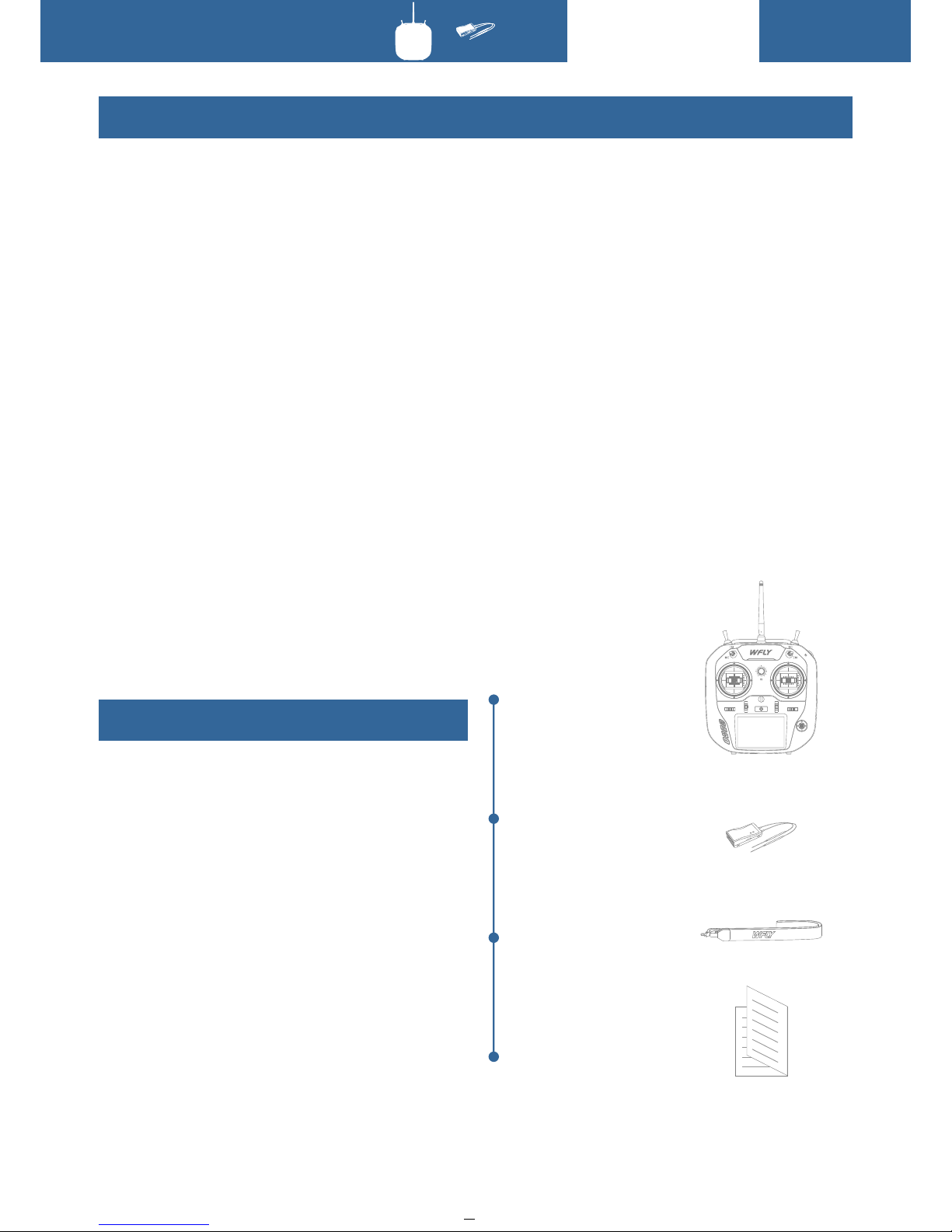
Basic Configuration
Transmitte r:ET07 re mote control ler x1
Recei ver:RF207S R eceiver x 1(External p ower
inspe ction wire x1)
Acces sary :
Lanya rd x1
Other s :
Summa ry manual file x 1
Warranty car d x1
*WFLY will not no tify furt her if any confi guratio n
chang es.
Product Features
Transmitte r
Recei ver
Lanya rd
Summa ry manual x1
10
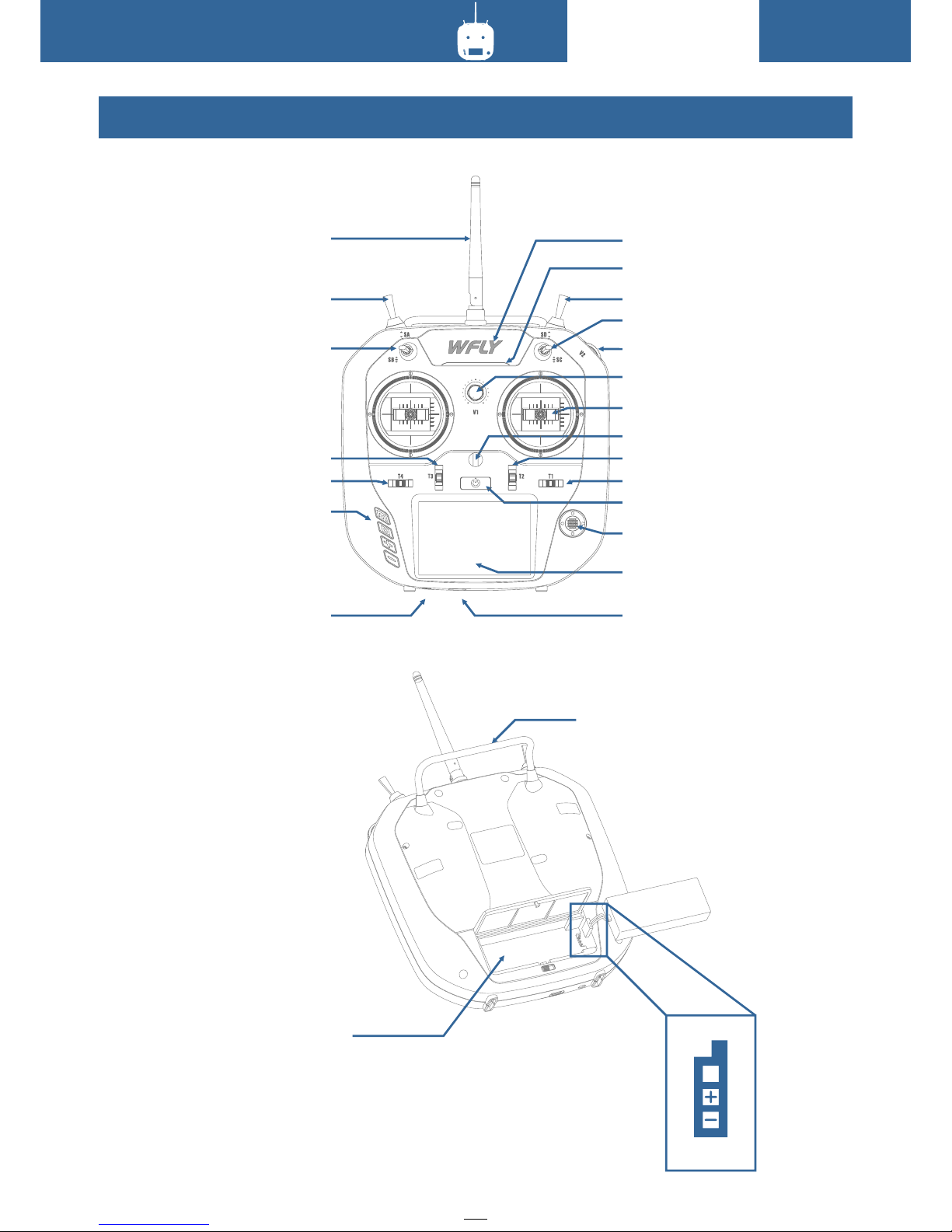
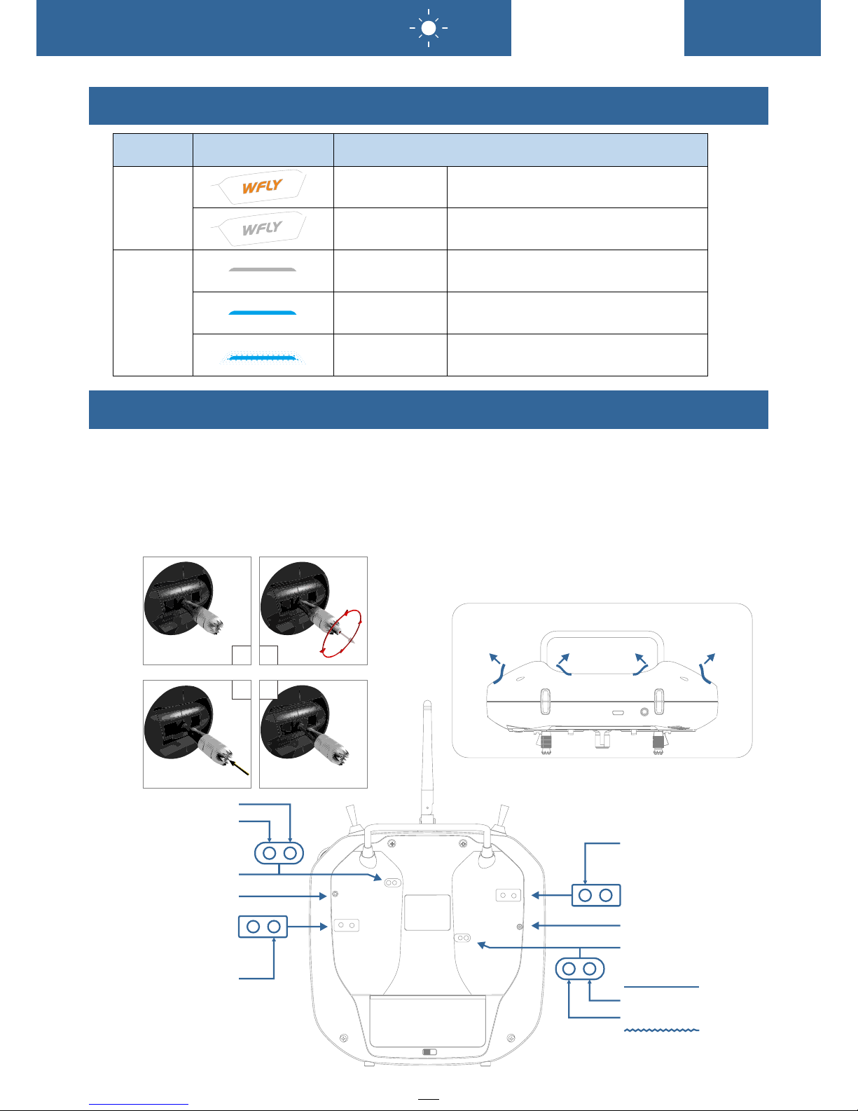
Each Parts Name of Transmitter
SA
SB
Funct ion key
Trainer port
Power L ED
RF Ligh t
SD
SC
V2(Sl ide Lever)
V1(Ro tary Knob)
Trim T1
Navig ate Key
Power s witch
USB Int erface
Resis tance touch sc reen
Stick
Hook
Batte ry compartme nt
Anten na
Trim T4
Trim T3 Trim T2
Carry h andle
Ba ttery Inter face
Before Use

11
The Travel Of Antenna Direction Adjustment
Switch Configuration And Types
Power s witch:Clic k and hold fo r about 2 second s to open/s hut down
T1-T4 :Trim k ey(User d efined funct ion)
SA:Sh ort lever 2 posi tions(U ser defined fu nction)
SB:Lo ng lever 2 posit ions(Us er defined fun ction)
SD:Sh ort lever 3 posi tions(U ser defined fu nction)
SD:Lo ng lever 2 posit ions rese t(User defin ed functi on)
V1:Ro tary knob(Us er define d)
V2:Sl ide Lever(Us er define d)
HO ME:Functi on key,slig htly click to r eturn t o standby int erfa ce,cl ick and hold fo r
2 se conds to turn o n the mon itor in terface.
EX IT:Return key,slig htly return t o the sup erior i nterface;Clic k and hol d for 2
se conds ,screen loc k and unlock
+: Incr ease key,param eter in creme nt,switch s tatus
-: Decrease ke y,pa rame ter decreme nt,sw itch st atus
Up/do wn/left/ri ght:Dir ection key
Middl e:Slightly c lick to con firm,press a nd hold to re set paramete rs(valu e)
Front a nd up movement 1 80°
The ant enna activit y of the tran smitter is lim ited by the s troke. If the ac tivity is exce eded, the a ntenna will
be dama ged.
The act ive travel ind ication o f the antenna is a s followi ng:
Le ft and right mo veme nt 180°
180
°
90
°
Before Use
12
Basic Operation
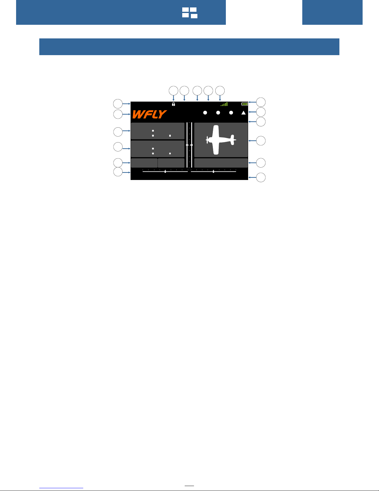
Home Interface Introduction
Opera tion and Intro duction
1.Transmit ter model
2.LOG O, Click to ente r main menu 3 .Normal Timer : Click and h old for reset, slightl y click for star t/pause
4.Mod e Timer:Click a nd hold for r eset,statu s is set by(Timer) menu
5.Volt age:Receiv er voltag e,external
5.Ret urn data(Ext ernal bat tery)
6.Trim monit or:disp lay active tri mming sta tus
7.Boo t time:The acc umulati on boot time , shu tdown res et
8.Mod el name: Click t o enter mod el selecting i nterfac e
9.Mod el types:Cli ck to enter c urrent machi ne type Int erface
10.Us er name:clic k into user d efined name
11.Trim s tatus:disp lay T1-T 4 trim stat us(T1-T4 whi le the swit ch being used) ,more det ails please re fer
to(Au x Channel)an d[Trim Setting ]
▲means t he position is " up"
●mean s the position i s "neutra l”
▼means t he position is " down"
12.Transmi tter batt ery capacity
13.Re ceiver signa l strengt h
14.Fl y mode(Throt tle lock, normal,Idl e1,Idle 2)
15.Mi xing:Displ ay the mixi ng after ACT the mixing fun ction
16.Working mo de:Display t hen ACT mod e(Trainer,sim ulator,s tudent)
17.Lo ck status(Cl ick and hol d EXIT/LOCK fo r 2s)
6
5
4
3
2
1
131415
16
9
10
8
7
12
T4
T3
T2
T1
11
SI M
RX
NO R
MI X
4. 2 V
00 : 0 6 : 5 9
0
0
0
0
00 00 0: .
00 00 0: .
Rx:5 . 0 V Ext: 1 2 V
ET07
Mode l 1
User N a m e
17
13
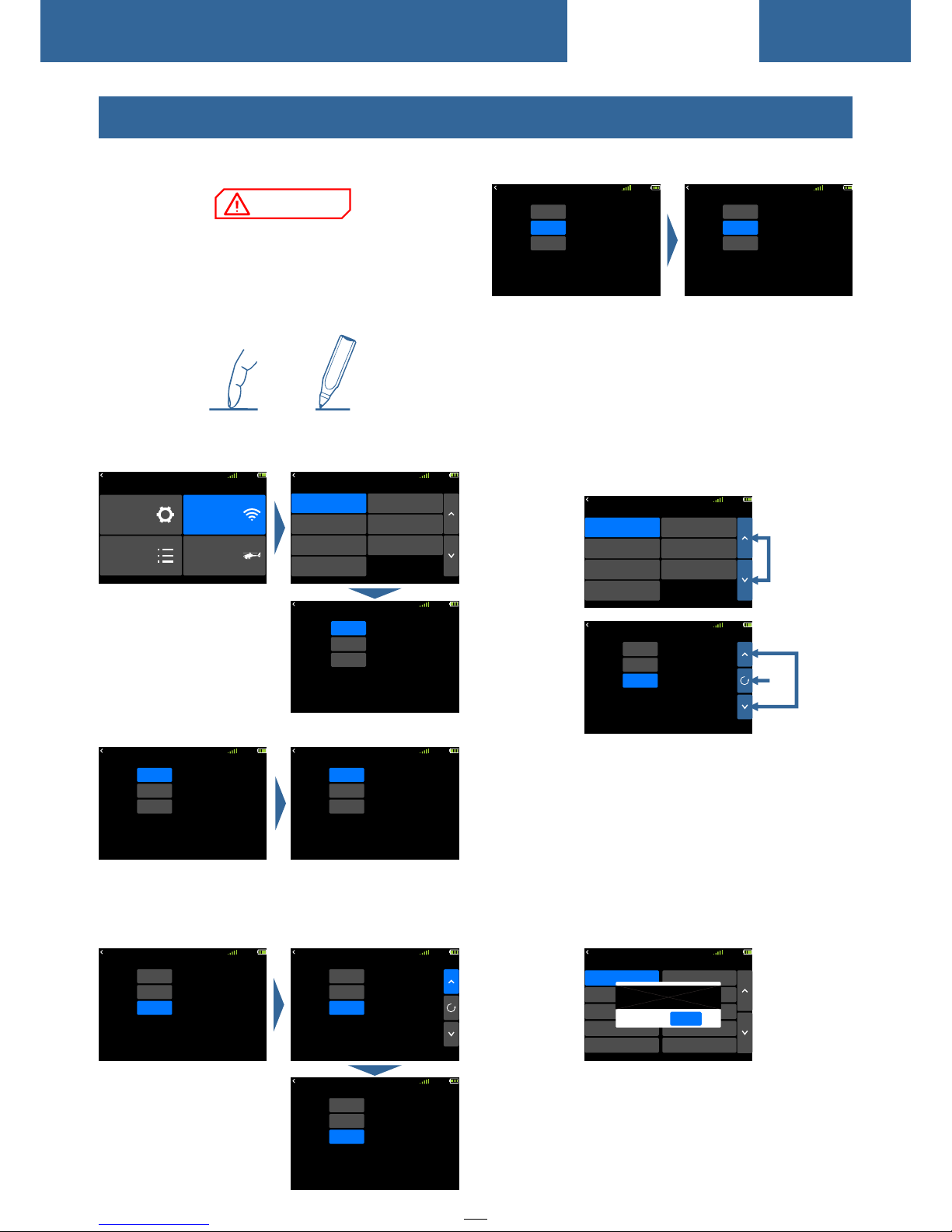
2 Switch , func tion type set ting: Click t o switc h.
Key function instruct ion
1 Page up a nd down key: Us ed for t urnin g pages
an d switc hing lists
2 Up a nd down key: Di splays when e ntering int o
value settin g, used for edi ting param eters
3 Reset key: bet ween UP/Down/+/- k eys, used
for rese t the default
Popup p rompt : When the operatio n changes
im portant paramet ers, th e selec tion box will p op up
for seco ndary c onfir mation. The d efau lt "No" i s
se lecte d.
Ex ample : The in terface mod el sele cting
op eration of (Mode l Selec ting) !Click a mode l
se lecting, th en pops u p a selec ting box, and then
cl ick confirm key means select "No" .
模拟 器
RX
NO RM
混控
4. 2V
00 :1 2: 02
ON
SA
Switch
Th ro tt le H ol d
Status
+1 0 %
Pos
②③
①
模拟 器
RX
NO RM
混控
4. 2V
Link
Range Check
Fail Safe
W.BUS Servo
PPM/W.BUS
Telemetry
Linkage Setting
Servo Frequency
00 :1 2: 02
RX
NO RM
4. 2V
Mo d e l 12
Mo d e l 13
Mo d e l 14
Mo d e l 15
Mo d e l 11
Mo d e l 17
Mo d e l 18
Mo d e l 19
Mo d e l 20
Mo d e l 16
00 :0 6: 59
Su r e ?
NO
OK
Model Select
ET07 us es 3.5 inches re sistanc e touch screen ,
which m akes ET07 oper ation mor e flexible and
effi cient.
Touch the t ouch screen so ftly with t he stylus pen
or your f ingertips. P lastic fi lm is attached t o the
touch s creen. Pleas e be carefu l so that you don' t
scrat ch the touch scr een with an ything hard su ch as
a metal o bject. Don't p ush the tou ch screen with
exces sive force or dr op anythi ng on the panel.
Operate Demonstrati on
Me nu Operati on: Cli ck ente r into the rela tive
in terface
St atus Switch : Click into sw itch st atus
Para meter s Setting:
1 Da ta setting: C lick and pop up t he uppe r right
se tup ke y, cli ck agai n the ke y to return the s et calu e .
RX
NO RM
4. 2V
00 :1 2: 02
ON
SA
Switch
Th ro tt le H ol d
Status
0%
Pos
RX
NO RM
4. 2V
INH
SA
Switch
Throttle Hold
Status
0%
Pos
00 :0 6: 59
RX
NO RM
4. 2V
Link
IN H
ModeA
Telemetry
Mode
Link
Start
00 :0 6: 59
RX
NO RM
4. 2V
00 :0 6: 59
Link
Range Check
Fail Safe
W.BUS Servo
PPM/W.BUS
Telemetry
Linkage Setting
Servo Frequency
RX
NO RM
4. 2V
Me nu
Linkage Setting
General Menu Model Menu
System Setting
00 :0 6: 59
Touch Screen Operation
RX
NO RM
4. 2V
00 :1 2: 02
ON
SA
Switch
Throttle Hold
Status
0%
Pos
RX
NO RM
4. 2V
00 :1 2: 02
ON
SB
Switch
Throttle Hold
Status
0%
Pos
RX
NO RM
4. 2V
00 :1 2: 02
ON
SA
Switch
Throttle Hold
Status
0%
Pos
RX
NO RM
4. 2V
00 :1 2: 02
ON
SA
Switch
Throttle Hold
Status
+1 0 %
Pos
RX
NO RM
4. 2V
00 :1 2: 02
ON
SA
Switch
Throttle Hold
Status
+1 2 %
Pos
Basic Operation
NOTICE
14
Statu s
Power
light
RF
light
LED
3
4
2
1
Stick h ead height adj ustment
Tools : 1.5 mm socket scre wdriver :
Steps :
1. Loos en the upper sec tion head
count erclockwis e
2. The n twist the l ower head to adj ust the hei ght
3. Twis t the upper h ead clockwis e to lock it
Stick f eel and functi on adjust ment
ET07 us es the newly dev eloped fo ur-bearing
assem bly to trim the fe el!
Uncov er the silicon e sheet on th e back and adjus t
the fee l directly.
Note: D o not use excess ive force o r over twist the
numbe r of turns when ad justing t he screw.
Other wise, the stru cture ass embly would be t wisted
off an d the screw m ay fall off, resulting i n
irrev ersible dama ge.
Soft si licon uncove r method
Upper a nd lower feeli ng
adjus tment positi on
Upper a nd lower elast ic
adjus tment positi on
Le ft and right el astic
ad justment po sitio n
Tooth adj ustment
Smoot h adjustment
Upper a nd lower feeli ng
adjus tment positi on
Upper a nd lower elast ic
adjus tment positi on
Smoot h adjustment
Tooth adj ustment
Left an d right elasti c
adjus tment positi on
Indicator Light of Transmitter
Stick Adjustment
Basic Operation
Power l ight on
Power l ight off
RF ligh t off
Off li ght on
RF ligh t flashes
Turn on,char ging
Turn off
Turn off ,student or si mulator m ode
Norma l linkage,tr ainer or no rmal mode
Enter l ink status
15
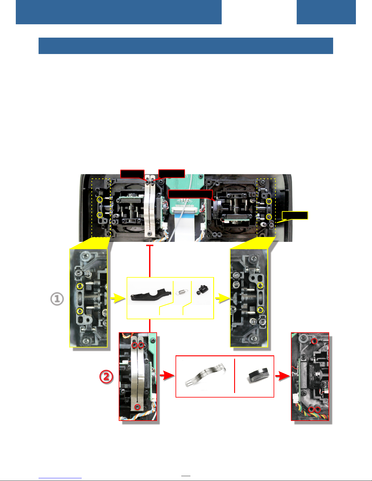
Stick Adjustment
Left an d right stick mo de replac ement method
It is not r ecommended t o replace t he left and righ t sticks by y ourself, oth erwise th e transmitte r may be
damag ed. (You r free warr anty would be lo st if you rep laced your lef t and right s ticks )
Requi red tools: 3 mm cr oss screw driver, 1.5 mm he x driver
First o pen the transm itter hou sing and then fo llow the in structions s hown belo w:
1 Loosen the bearing housing screws (the screws do not need to be fully retracted), then remove
the spring, bracket 7 and bracket 5 and tighten the screws; then remove th e removed s pring, brack et 7
and bra cket 5 in anothe r assembl y correspond ing posit ion (remove th e bearing h ousing screw b efore
assem bly),The tig htness of t he stick can be ch anged by ad justing the he ight of scr ew 3.
2 Remove the screw of the throttle reed, the throttle reed and the throttle sleeve, and install them
in the corresponding position of the other assembly. According to your own habits, select the type
of throttle sliding (toothed and smooth) and adjust the screw (screw 1 or The height of the screw 2)
makes the damping of the throttle conform to your own habits.
Screw1
Screw2
Sc rew 3
Th rott le slee veTh rott le reed
After t he throttle st ructure i s modified, tur n on the mach ine, enter [sy stem setting ] → [stick mo de], select
the cor responding o peratio n mode, and then a djust the s tick after rep lacing th e left and right m odes!
If you ne ed component s such as bra cket 5 (such as th e parts nee ded for assemb ling doub le circuit
struc ture!), you ca n e-mail to W FLY over seas sell er to order the sp are parts a t sales@wflys z.com
Brack et 5 Brack et7
Sprin g
①
Throt tle sleeve
Basic Operation
16
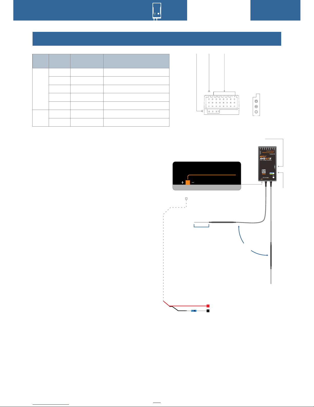
Receiver Instructions
Recei ver Operatio n Wa y
1 Link: C harge the rece iver then p ress and hold
'SET' b utton for 3 seco nds,wai t for the link
instr uction after t he orange l ight slowly fl ashes.
2 PM/W.B US/PWM port mo des selec t: Click and
hold th e "SET" to charg e, then ent er into model
setti ng, slightly c lick the sw itcher mode, p ress and
hold to c onfirm.
Recei ver connecti on and inst allation
Notic e:pay attent ion to the po sitive and neg ative
polar ity when conne cting the p ower supply. Do not
use the p ower supply th at exceed s the working
volta ge of the receiv er. Otherw ise, the recei ver will
be dama ged!
The RF2 09S is the lates t series of h igh
perfo rmance recei ver with 7 PW M channels, 1
PPM/W. BUS channel (U ser defin ed), and 1 W.BUS2
chann el (User defin ed).
In orde r to obtain opti mal signa l retrieval
perfo rmance, the tw o antenna s are preferab ly
proce ssed 90° to each o ther when i nstalled, as
shown i n the bottom rig ht diagra m.
Notic e:
1.If th ere is a metal con ductor ar ound the recei ver
anten na,the signa l perform ance would be affected .
In this c ase, the anten na should b e bypassed by th e
condu ctor, placed on b oth sides o f the fuselage , and
it is bet ter to make the an tenna lea k outside the
model c asing ! In this wa y, good sig nal recep tion can
be main tained regar dless of th e flight attit ude.
2. When t he antenna is in stalled . The unsh ielded
end of th e antenna shou ld be as far aw ay as
possi ble from the con ductor ma terials such a s metal
and car bon fiber. The antenna ca ble avoid s bending
at larg e angles. And the e nd core sho uld be as
strai ght as possibl e.
3. If the m odel body is cov ered with a c onductive
mater ial such as carb on fiber or m etal, the ante nna
porti on must be exten ded beyon d the body. At the
same ti me, do not stick t oo close to t he conductiv e
Recei ver LED STATUS LIST
Si gnal
Positive
Ne gtive
Mode
LED
Actio n
State
Work
Set
Bl ue
Green
Red
Orange
Red
Green
Bl ue
Never
Never
Never
Slow fl ash
Slow fl ash
Slow fl ash
Slow fl ash
W.BUS no rmal work mode
PWM nor mal work mode
No sign al
Low vol tage
Linki ng
W.BUS mo de
PPM mod e
US B port
90°
Ext.voltage
Exter nal voltage de tection p ort
An tenna
Keep st raig ht
Th e red is c onnec ted to
th e posit ive po le
Th e resistanc e is conn ected to
th e negative po le
1Ω resi stance
Basic Operation
LED
PPM/W.BUS/W.BUS2
CH1~7:PWM
PPM/W.BUS
body af ter the antenn a is extend ed. In additio n, the
anten na should also b e kept away f rom the fuel
tank.
17
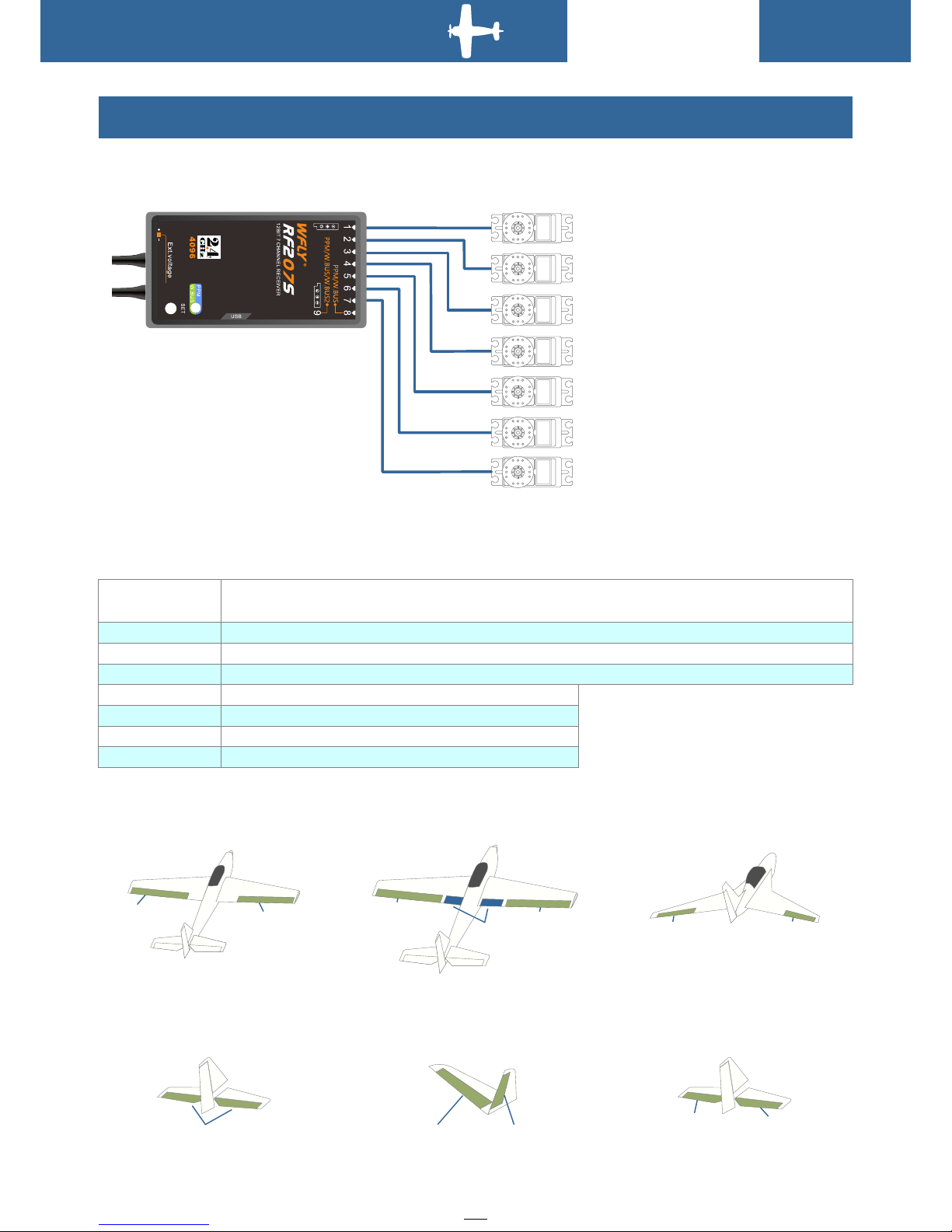
Receiver and servo Link example
CH6
FLAP
CH5
UNDER CARRIAGE
CH4
RUDDE R
CH3
THROT TLE
CH2
ELEVATOR
CH1
AILER ON
CH7
AILER ON 2/AUX 1
- Airplane
Th e figure belo w shows a n examp le of airplan e Link. P lease u se the actual w ing ty pe and ta il typ e for
se rvo Li nk.
Wing
Tail
(Norm al)
ELE
(CH2)
(V-Tail) (*4)
ELE2
RUD1
(CH4)
ELE1
RUD2
(CH4)
(Ailv ator)
AIL3
(CH2)
ELE1
(CH1)
ACRO( Flaperon)( *2)
AIL 1
FLP 2
(CH 1)
AIL 2
FLP 1
(CH 6)
ACRO( AIL Different ial)(*1 )
FLP
(CH 6)
AIL 1
(CH 1)
AIL 2
(CH 7)
ACRO( Ailvator)( *3)
AIL 1
ELE 2
(CH 1)
FLA 2
ELE 1
(CH 2)
Servo connection position (Airplane)
The tab le below shows e xamples o f the servo conn ection po sitions for th e differ ent wing ty pes and tail
types .
Airpl ane(ACRO)
1
Ailer on/Aileron 1(*1)1A ileron1(Ai leron2) (*2)/Ailer on1(Ele vator2)(*3 )
2
Eleva tor/Elevat or1(Ail eron2)(*3) /Elevat or1(Rudder 2)(*4)
3
Throt tle
4
Rudde r/Rudder1( Elevato r2)(*4)
5
Spare /undercarr iage
6
Spare /Flap/Flap 1(Ailer on 2)(*2)
7
Spare /Aileron2( *1)
Recei ver
outpu t channel
(*1)W hen it's AIL Diffe rential
(*2)W hen it's Flape ron
(*3)W hen it's Ailvat or
(*4)W hen it's V-Tail
Basic Operation
 Loading...