

Wfly ET06 Instruction Manual

WFLY
Shenzhen WFLY Technolog y Development Co., Ltd
WFLY Wechat
(ET Seri es) 6-channel Di gital Proportio nal R/C Sys tem
ET06 INSTRUCTION MANUAL
01

Thank you for using WFLY prod ucts!
● Please read this product ma nual ca refully before using this product!
● Please use this product cor rectl y!
The model is not a toy, for saf ety, please don't fly at crowded places!
——Shenzhen WFLY Technology De velop ment Co., Ltd
02

CATALOGUE
A
Safety Precautions
06
Symbols Definition
06
Flying Precautions
07
Battery
08
Trainer Port
08
USB Port
B
Before Use
09
Product Features
09
Basic Configuration
10
Each Parts Name Of Transmitter
11
Switch Configuration and Model Types
11
The Travel of Antenna Direction Adjustment
C
12
13
13
14
15
16
17
18
D
19
20-21
Basic Operation
Home Interface Introduction
Indicator Light of Transmitter
Stick Adjustment
Left and Right Hand Mode Replacement Method
Receiver Instructions
Receiver and servo connection example:
-Airplane
-Helicopter
-Multicopter
Basic Setting Sequence of Models
-Airplane
-Helicopter
03

E
System Setting
22
Model Select
23
Model Type
24
Trainer
25
Display
26
User Name
27
Low Battery
28
Sound
29
Language
30
Stick Mode
31
Calibration
32
Data Reset
33
Information
CATALOGUE
34
Screen Lock Set
F
Linkage Setting
35
Link
36
Telemetry
37
PPM/W.BUS
38
Receiver Output
39
Fail Safe
40
Relay Flight
41
Servo Frequency
42
BUS Servo Setting
43
180/270° Servo
44
Range Check
G
General Menu
45
Monitor
46
Function
47
Servo Reverse
48
Dual Rate
49
End Point
50
Timer
51
Trim Setting
52
Sub-Trim
53
Channel Delay
54
Program Mixes
55
Flight Mode
56
Double Engine
04

CATALOGUE
H
Model Menu\Helicopter
57
Condition
58
Throttle Curve
59
Pitch Curve
60
Throttle Hold
61
Throttle Cut
62
Gyro
63
Governor
64
Swash
I
Model Menu\Airplane
65
Condition
66
AIL Differential
67
Throttle Curve
68
Throttle Hold
69
Throttle Cut
70
Gyro
71
Airbrake
72
ELE to Camber
73
Winglet
74
Elevator
75
V-Tail
76
Flywin
J
Model Menu\Multicopter
Condition
77
78
Throttle Curve
79
Throttle Hold
Throttle Cut
80
81
Stick Alarm
82
Gyro
05

Safety Precautions
WARNING
DANGER
NOTICE
WARNING
DANGER
NOTICE
Symbols Definition
Pay special attention to th e safety information of the following s ymbols!
If without a proper operati on,it may cause dangerous accident or seriou sly inj ury or
may even cause death.
If without a proper operati on,it may cause dangerous accident or seriou sly inj ury or
may even cause death,and it m ay caus e slight hurt or probability cause bodi ly inju re!
If without a proper operati on,it m ay cause less possibility to serious hu rt,bu t it may
cause hurt or bodily injure .
Prohibitions
Mandatory
Flying Precautions
Disclaimer & Warning
User should be responsibl e for any c onsequences caused by using the product. WFLY shall n ot be liable
for any directly or indirec tly dam age, injury and any legal liability, User sh all com ply with all guidelines
including but not limited t o this do cument.
Please follow the local law s and reg ulations for regular flight activiti es. Do no t use this product to carry
out personal safety, pr opert y safety or other bad flight behaviors.
To ensure the safety of you rself a nd others, please observe the followi ng precautions:
Charge the batteries! Che ck tran smitter and receiver battery level an d alway s recharge the batteries
before each flying session . A low battery will soon die potentially, causi ng loss o f control and a crash. When
you begin your flying sessio n, rese t your ET06 built-in timer, and during the s essio n, reset your ET06 builtin timer, and during the sessi on pay at tention to the duration of usage.
Be careful when flying near el ectri c wires, high-rise buildings or communicat ion facilities, as there may
be radio interference aro und.
Mandatory
Beginners should pay part icula r attention to the following safety pre cauti ons! Please read carefully!
No fly when user is in poor health c ondit ion such as fatigue and drunkenness.
No fly in bad weather day such as ra in, str ong wind or at night, etc.
No fly near high voltage wires , commu nication base stations, governmen t secre t zone or public places
where crowds gathered.
No fly in airports and other pla ces whe re fly is forbidden.
Before flying, inspect the a ircra ft carefully, inspect whether the a ircra ft and transceiver system it's
normal. When flying, make th e transmitter display to the initial interfa ce, in ca se of mistaken parameter
change. After flight, turn off t he receiver power before turn off the transmitt er powe r, in case of any injury
caused by fail safe works.
More debugging, more test ing, le ss loss, less damage!
Mandatory
Power on and off sequency of tra nsmit ter and receiver!
Power on:
Firstly turn on the tr ansmi tter (ensuring the minimum throttle positi on), Secondly Turn on the receiver.
Power off:
Firstly turn off the receive r, Secon dly turn off the transmitter.
Transmitter and receiv er low vo ltage may cause fail-safe danger!
Note: The transmitter wil l display the warning interface, plea se pay attention to the transmitter
prompt! Improper ly oper ation may cause accident injury to user.
06

Safety Precautions
NOTICE
NOTICE
DANGER
Battery
Lithium polymer battery (Shor t for LiFe battery),please use the WFLY specia l charger only.It is important
to understand the operati ng char acteristics of Li-Fe batteries.
Long term storage (more tha n 3 month s),storage temperature≤45°C gen eral st orage voltage 3.7-3.9v.
Failure to follow the proce eding p recautions can quickly result in seve re, per manent damage to the
batteries and possibly re sult in a fi re!
1.Do not attempt to disasse mble Li Fe packs or cells.
2.Do not allow LiFe cells to co me in con tact with moisture or water at any time.
3.Always provide adequa te vent ilation around LiFe batteries during charg e, discharge, while in use, and
during storage.
4.Do not leave a LiFe battery u natte nded at any time while being charged or discharg ed.
5.Do not attempt to ch arge Li Fe batteries with a charger that is NOT designed for L iFe batteries, as
permanent damage to the bat tery an d charger could result.
6.Always charge LiFe batt eries i n a fireproof location. Do not charge or dis charg e LiFe batteries on
carpet, a cluttered workb ench, n ear paper, plastic, vinyl, leather or wo od, or in side an R/C model or fullsized automobile! Monit or the ch arge area with a smoke or fire alarm.
7.Do not charge LiFe batter ies at cu rrents greater than the “1C” rating of th e batte ry (“C” equals the rated
capacity of the battery).
8.Do not allow LiFe cells to ov erhea t at any time! Cells which reach greater th an 140 de grees Fahrenheit
(60°C) should be placed in a fir eproo f location.
9.LiFe cells will not charg e fully w hen too cold or show full charge.
10.It is normal for th e batte ries to become warm during charging, but if the ch arger o r battery becomes
excessively hot disconn ect the b attery from the charger immediately !! Alway s inspect a battery which has
previously overheated f or pote ntial damage, and do not re-use if you susp ect it ha s been damaged in any
way.
11.Do not use a LiFe batter y if you su spect physical damage has occurred to the pack . Carefully inspect
the battery for even the smal lest of dents, cracks, splits, punctu res or da mage to the wiring and
connectors.DO NOT al low the b attery’s internal electrolyte to get into eyes o r on skin—wash.affected areas
immediately if they come in c ontac t with the electrolyte. If in doubt, plac e the battery in a fire-proof location
for at least 30 minutes.
12.Do not store batteries n ear an op en flame or heater
13.Do not discharge LiFe ba tteri es at currents which exceed the dischar ge curr ent rating of the battery.
14.Always store LiFe cell s/pac ks in a secure location away from childre n.
Transmitter (ET06):
ET06 adopts the power suppl y mode of l ithium battery, and the working voltage ad apts to the range of
3.7-6V. Using a power supply that ex ceeds the operating voltage stroke may burn th e machi ne!
The USB interface of ET06 can b e used to charge the common mobile phone charger ( 5V)!
Receiver (RF206S):
The receiver's operatin g volta ge adapts to the range 3.8V-6.5V, with anti-rev erse pr otection slot (power
input pole, positive and ne gativ e reverse protection). With a power sup ply tha t exceeds the operating
voltage stroke, the recei ver wil l burn out!
07
Safety Precautions
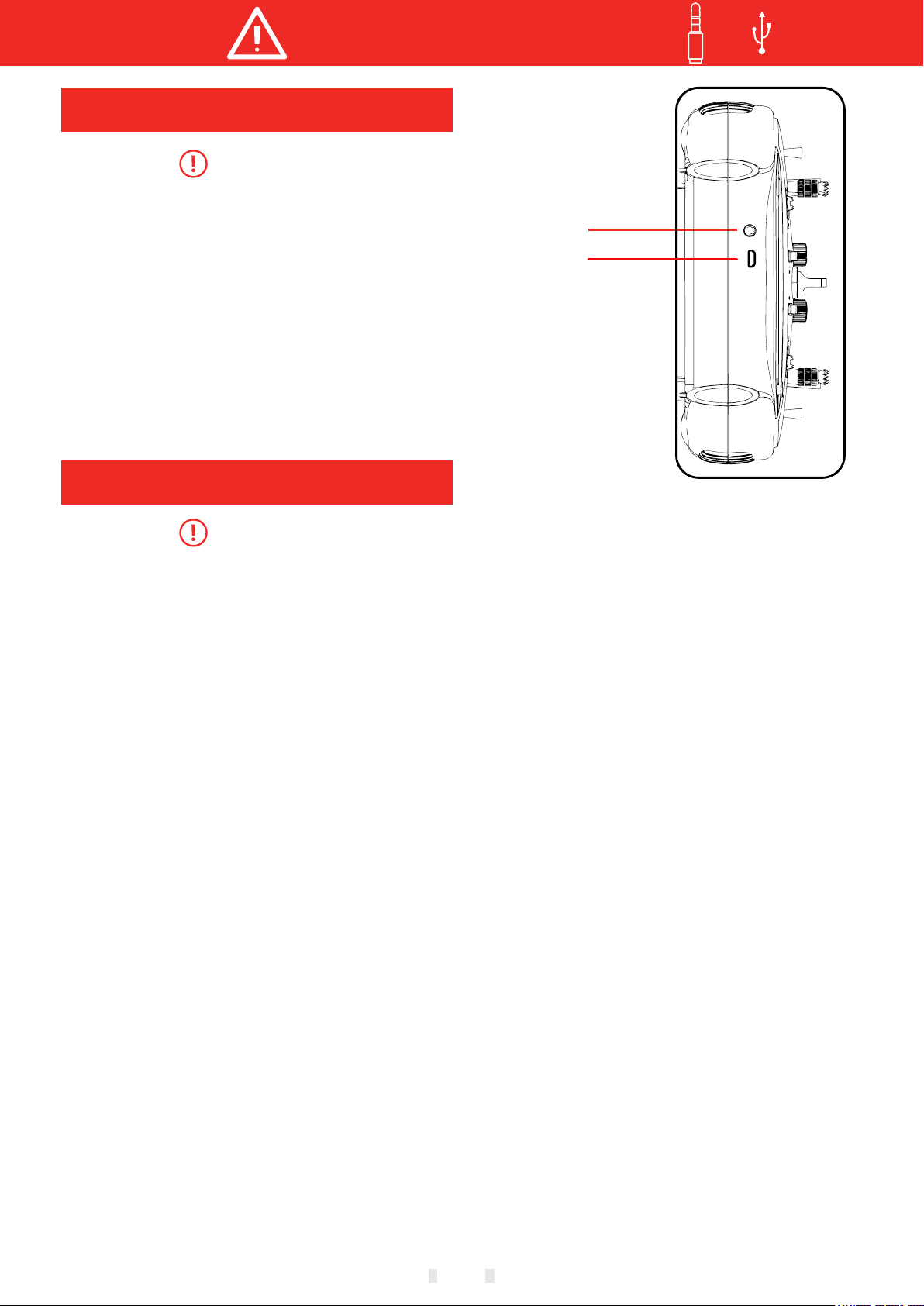
Trainer Port
Mandatory
Transmitter trainer port :
The trainer port is with 3.5m m audio p ort output
mode. This suite is without the t rainer data line. If
you want to use the trainer fun ction , you need to
purchase the trainer data l ine sep arately!
Warning: This port is only use d for tra iner data
transmission. It is forbi dden to insert the power
supply (high voltage) ter minal t o the port to avoid
damage for the transmitte r.
USB Port
Trainer/Simulator po rt
USB port
Mandatory
Transmitter USB port:
ET06 adopt standard USB port for upgrading
function!
Warning: This port is only used as upgrading
data transmission, it is forbidden to insert the
power supply (high voltage) terminal to the USB
port to avoid damage for the transmitter
08

Before Use
Product Features
Transmitter
Model: ET06
Channel: 6 channels
Voltage: 3.7V-6V (1S lithiu m batte ry)
Current: 150mA
Applications: helicop ters/ airplanes/multicopters/robo ts/ca rs/ boats
Resolution: full channe l 4096
Band: 2.4GHz(bidirect ional )
HFSS:64points,3.6ms
Storage: 5 groups
Program: 5 program mix
Language: Chinese, Engl ish
Upgrade: USB upgrade
Display: 3.5 inches, 128x 64 dot ma trix screen
Relay flight: support
180/270° servo: support
Wireless copy: model data
Receiver
Type: RF206S
Band: 2.4GHz
Voltage: 3.8V-6.5V
Current: 80mA
Applications: helicop ters/ airplanes/multicopters/robo ts/ca rs/ boats
Frequency: FHSS 4096
PWM: 6 channels
PPM: support
W.BUS: compatible S.BUS
Two-way transmission: su pport
Fail-safe: support
180/270° servo: support
Receiver port setting: su pport
External voltage detect ion: DC 0 ~36V
Dimention: 36x20x12mm
Basic Configuration
ET06 transmitter x1
RF206S receiver x1(incl ude ext ernal power detection line x1)
Summary manual x1
Transmitter
Receiver
Summary Manual
09
Carry handle
Before Use
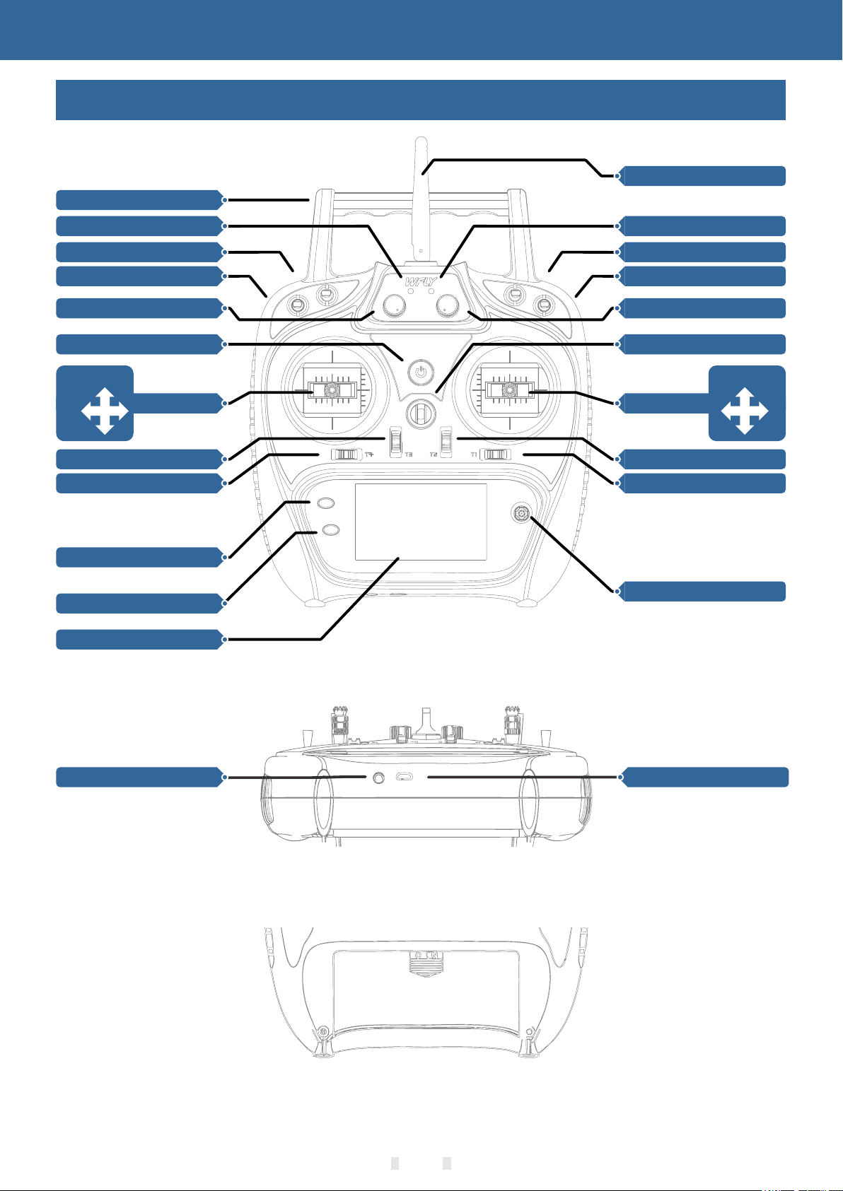
Each Parts Name Of Transmitter
Antenna.
SB Switch Block
SA Switch Block
LD Rotary Knob
J3
J4
HOME/MON.
Power LED
Power Key
Stick
Trim3
Trim4
EXIT/LOCK
RF LED
SC Switch Block
SD Switch Block
RD Rotary Knob
Hook
J2
Stick
Trim2
Trim1
5-way Button
J1
Display Screen
TRAINER
USB Upgrade Port
Battery cover
10

Before Use
Switch configuration and model types
Power LED: Left, power indi cator l ight, red
RF LED: Right, RF indicator l ight, b lue.
POWER: Click and hold for 3 seconds to o pen/s hut dow n;
SA: Short lever 2 positions (user- define d)
SB: Long lever 3 positions (user-defined)
SC: Long lever 3 positions (user-defined)
SD: Short lever 2 positions (user- define d)
LD/RD: Rotary Knob(User-defined)
T1-T4:Trim,(User-defined)
TRAINER: Trainer port
5-way button: Move the cursor butt on up and d own or left and right, middle button fo
press to reset).
HOME/MON.: Home/Monit or key, slig htly click home, press and hold monitor.
EXIT/LOCK: Exit/Lock ke y, sl ightly click to exist, press and hold to lock the screen.
r confirmation(Long
The Travel Of Antenna Direction Adjustment
Mandatory
Avoid metal objects covering the handle position when in use.
The following is the "antenna position indication image" and "signal strength and position
relationship diagram":
Receiver faces upside
As the picture shows
Transmitter faces upside
As the picture shows
Strong
signal acquisition
Weak
signal acquisition
11

Basic Operation
Home Interface Introduction
Home Interface 1
Home Interface 2
18
1
2
3
4
18
19
17
5
6 7
23
14
15
16
13
12
11
10
9
8
22
20
21
Introduction and o perat ion
1-20.Timer 1
2.Return data(Receive r volta ge)
3.Return data(Externa l batte ry)
4-5-7-8.Trim monitor, d ispla y active trimming status
6."Home2" key, click to e nter Ho me Interface 2
9.Model name: Click to ente r model s elect interface
10.Model type: Click to ent er current model type interface
11-21.Timer 2
12.User name, click into us er defin ed name
13.Transmitter batte ry volt age
14.Lock(Click EXIT/LO CK 2s to enter lock status)
15.Receiver signal stre ngth
16.Student (S), Trainer( T), 8channel simulator(8)mode status
17.Throttle hold ( ) and thro ttle cut ( )status
18.Fly mode, current fly mod e
19.Return data(Receiv er volt age)
22.Return data(Extern al batt ery voltage)
23."Home interface2", “Confi rm Key”"Return Key" or"Home Key" swit ch back t o "Home Interface 1"
12

Basic Operation
LED
Status
Power LED on
Power on
Power LED off
Power off
RF LED off
Power off , Student or Sim ulato r mode
RF LED on
Normal Linkage, Trainer or N ormal m ode
RF LED flash
Enter link status
Indicator Light of Transmitter
Power LED
Red
RF LED
Blue
Stick Adjustment
Stick head height adjustm ent:
1. Loosen the upper section h ead cou nterclockwise
2. Then twist the lower head to adj ust the height
3. Twist the upper head clockwis e to lock i t
13
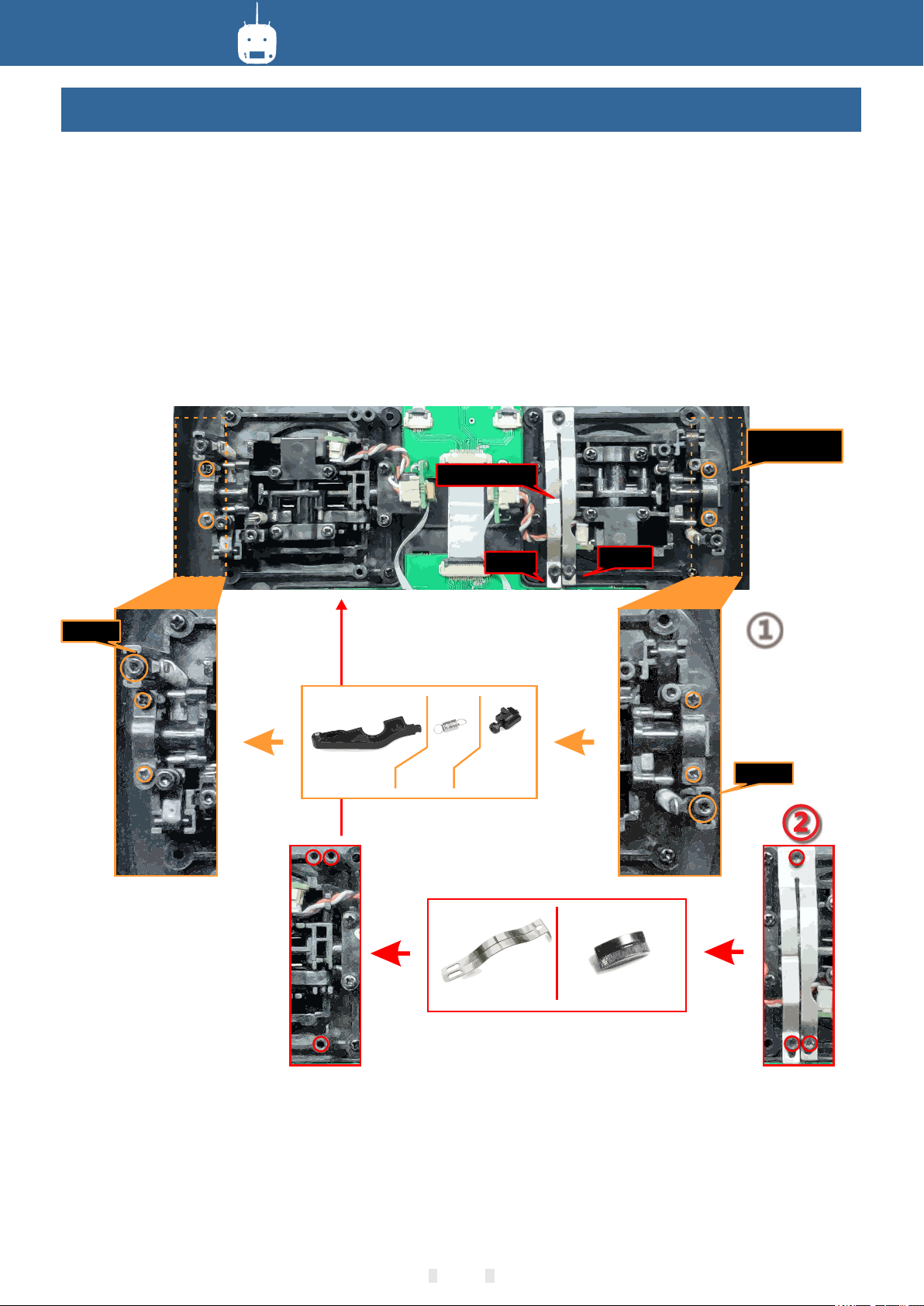
Basic Operation
Left and right stick mode replacement method
It is not recommended to replace the l eft and r ight sticks by yourself, otherwise the transmitte r may be
damaged.
Required tools: 3 mm cross screwdriver, 1.5 mm hex dr iver
Firstly open the transmit ter hou sing an d then follow the instructions shown below:
1 Loosen the bearing housing screws (the screws do n ot need t o be full y retracted), then remove the
spring, bracket 7 and bracket 5 and tighten t he scre ws; the n remov e the removed spring, bracket 7 and
bracket 5 in another assembly corresponding po sitio n (remo ve the be aring housing screw before
assembly),The tightness of th
2 Remove the screw of the throttle ree d, the th rottle reed and the throttle sleeve, and install them i n the
corresponding position of the other assembly. Acco rding t o your ow n habits, select the type of throttle
sliding (toothed and smooth) and a djust t he scre w (screw 1 or The height of the screw 2) makes the
damping of the throttle conform to y our own h abits .
e stick can be changed by adjusting th e heigh t of scre w 3.
Bearing
housing screw
Throttle sleeve
Screw 3
Bracket 5
Screw 2
Spring
Bracket 7
Throttle reed Throttle sleeve
Screw 1
①
Screw 3
After the throttle struct ure is mo dified, turn on the machine, enter [system setting] → [s tick mo de], select
the corresponding operation mode, and t hen adj ust the s tick after replacing the left and right modes! If you
need components such as bracket 5 (such as th e parts n eeded for assembling double circuit structure!), you
can e-mail to WFLY overseas seller to order the spar e parts a t sales@wflysz.com.
14

Basic Operation
Mode
LED
Action
Status
Work
Purple
Never
PWM normal work mode
Green
Never
W.BUS normal work
Blue
Never
PPM normal work mode
Red
Never
No signal
Red
Slowly flash
Low voltage
Orange
Slowly flash
Linking
Ext.voltage
Receiver Instructions
Receiver LED STATUS LIST
Link: Charge the receiver t hen pre ss and hold
'SET' button for 3 seconds, wait for the link
instruction after the ora nge lig ht slowly
flashes(LINKAGE SETTI NG)→(LINK).
W.BUS/PPM/PWM
Negative
Positive
Signal
PPM/W.BUS/PWM por t modes s elect: Enter the
interface [LINKAGE SETT ING] - [RECEIVER
OUTPUT], switch th e worki ng status of the last port
of the receiver (default 6 ch annel s), and return to
the previous interface to s ave the settings.
Receiver connection and i nstallation
The working voltage of the re ceive r is 3.8-6.5V.
Each port can be used as the powe r input t erminal.
Notice: pay attention to th e positive and negative
polarity when connectin g the pow er supply. Do not
use the power supply that exc eeds th e working
voltage of the receiver. Oth erwis e, the receiver will
be damaged!
The RF206S is the newest seri es of hig h
performance receiver wi th 6 PWM ch annels, the last
channel port is PWM/PPM/W. BUS channel (User
defined).
In order to obtain optimal si gnal re trieval
performance, the two ante nnas ar e preferably
processed 90° to each other w hen ins talled, as
shown in the right diagram.
External voltage detect ion
port polarity signs
90°
The resistance is connect ed
to the negative pole
1Ω
The red is connected to the
positive pole
Keep the
antenna
straight
Mandatory
1.If there is a metal conduct or around the receiver antenna,the signal pe rform ance would be affected.
In this case, the antenna sho uld be by passed by the conductor, placed on both si des of th e fuselage, and
it is better to make the a ntenn a leak ou tside the model casing ! In this way, goo d signa l reception can be
maintained regardless o f the fli ght attitude.
2. When the antenna is instal led. The unshielded end of the antenna should be as fa r away as p ossible
from the conductor materi als such as metal and carbon fiber. The antenna cable a voids b ending at large
angles. And the end core shoul d be as str aight as possible.
3. If the model body is covered w ith a conductive material such as carbon fiber o r metal , the antenna
portion must be extended be yond th e body. At the same time, do not stic k too clo se to the conductive body
after the antenna is extend ed. In ad dition, the antenna should also be kept a way fro m the fuel tank.
The receiver has an externa l batte ry detection interface, which can be us ed to vie w voltage information
such as ESC, battery, etc ., and th e transmitter can separately set alar m volta ges for the receiver voltage
and external voltage. Pay a ttent ion to the positive and negative polari ty when u sing the detection wire!
15

Basic Operation
Type No. Wing Delta wing Tail
Airplane
1 1 AIL Normal
Channel AIL ELE THR RUD Gear Aux1
Control J1 J3 J2 J4 SD --
Trim T1 T3 T2 T4 -- --
2 1 AIL V-Tail
Channel AIL ELE THR RUD Gear Aux1
Control J1 J3 J2 J4 SD --
Trim T1 T3 T2 T4 -- --
3 1 AIL Ailevator
Channel AIL ELE THR RUD Gear ELE2
Control J1 J3 J2 J4 SD --
Trim T1 T3 T2 T4 -- --
4 2 AIL Normal
Channel AIL ELE THR RUD Gear AIL2
Control J1 J3 J2 J4 SD --
Trim T1 T3 T2 T4 -- --
5 2 AIL V-Tail
Channel AIL ELE THR RUD Gear AIL2
Control J1 J3 J2 J4 SD --
Trim T1 T3 T2 T4 -- --
6 2 AIL Ailevator
Channel AIL ELE THR RUD ELE2 AIL2
Control J1 J3 J2 J4 --
Trim T1 T3 T2 T4 -- --
7 2AIL Normal
Channel AIL ELE THR RUD Gear AIL2
Control J1 J3 J2 J4 SD --
Trim T1 T3 T2 T4 -- --
8 2AIL W inglet
Channel AIL ELE THR RUD RUD2 AIL2
Control J1 J3 J2 J4 SD --
Trim T1 T3 T2 T4 -- --
CH1 CH2 CH3 CH4 CH5 CH6
Receiver and servo connection example - Airplane
The figure below shows an exa mple of a irplane connection. Please use the actual wi ng type a nd tail type
for servo connection.
CH1/Aileron
CH2/Elevator
CH3/Throttle
CH4/Rudder
CH5/Gear
CH6/Aux1
Servo connection p ositi on (Airplane,refer to stick mode "Mod e 1")
The table below shows examp les of th e servo connection positions for the di ff erent w ing types and
tail types(system defau lt settings)
16

Type No. Swash
Helicopter
1 H-1
Channel AIL ELE THR RUD Gyro PIT
Control J1 J3 J2 J4 -- J2
Trim T1 T3 T2 T4 -- --
2 HR3
Channel AIL ELE THR RUD Gyro PIT
Control J1 J3 J2 J4 -- J2
Trim T1 T3 T2 T4 -- --
CH1 CH2 CH3 CH4 CH5 CH6
Basic Operation
Receiver and servo connection example - Helicopter
The figure below shows an exa mple of h elicopter connection. Please use the swash t ype that is actually
used for the servo connecti on.
CH1/Aileron
CH2/Elevator
CH3/Throttle
CH4/Rudder
GRO
Servo connection position (Helicopter,refer to stick mode "mode 1")
The table below shows examples of the servo connection positions for different swashes.
Swash Types
Normal
H-1
PIT
HR3(120°)
AIL
ELE
CH5/Gyro
CH6/Pitch
17

Type No.
Multicopter 1
Channel AIL ELE THR RUD Flight mode Aux1
Control J1 J2 J3 J4 -- --
Trim T1 T2 T3 T4 -- --
CH1 CH2 CH3 CH4 CH5 CH6
Basic Operation
Receiver and servo connection example - Multicopter
The figure below shows the fo ur-ro tor multicopter. Please refer to the mod el manu al for specific
applications. Motor,el ectro nic speed controller, flight control ler, bat tery, etc. are sold separately.
Motor、ESC
(buy seperately)
Use 5CH-6CH when using acce ssori es such
as camera shutters. Use a W.BU S interface or
dual receiver when the chan nel is in sufficient.
CH1 Aile ron
CH2 Ele vat or
CH3 Thro ttle
CH4 Rud der
CH5
Multi cop ter
fli gh t con tro lle r
Battery
This figure is for illustra tive pu rposes only. Link amplification also cha nges de pending on the multicopter
collective and the flight c ontro ller. Please connect according to the in struc tion manual of the multicopter kit
to be used.
Servo connection positi on (Multicopter,refer to stick mode" Mode 1")
18

Basic Operation
Basic setting sequence of airplane
1. Call of the model
The ET06 transmitter has 5 bu ilt-in models from
the factory, and you can us e the [MO DEL SELECT]
under [SYSTEM SETTING] to c all up the existing
model.
The Rename feature makes it e asy to make a
selection call to a model who se name h as already
been set.
The name of the model current ly in use i s
displayed on the home page. B efore fl ying and
changing the parameter se tting s, be sure to
determine if the correct mo del is selected.
When a new model is added, plea se sele ct
[MODEL TYPE] under [SYSTEM S ETTING]
according to the model used . If a new re ceiver is
used, the receiver's link o perat ion is also
required[LINKAGE SETT ING]-[LINK].
2. Model type select ion
Use the [MODEL TYPE] fu nctio n under [SYSTEM
SETTING] to select t he mode l type, wing type, and
tail type that match the mode l airpl ane.
For example, the left and rig ht azimuth servos
can be selected from the main w ing typ e by
selecting "2 ailerons" an d adjus ting the two servos
in [SUB-TRIM] and [END POIN T] respectively.
3. The fuselage cont rol par t connect
Install the ailerons, ele vator s, throttles, rudders,
etc. as required by the model a ircra ft product
specification. For the con necti on method, refer to
the "Receiver and Servo Con necti on Example Airplane" (P16).
Note: ET06 transmitters h ave different channel
assignments depending o n the mod el type, so
please pay special attent ion (in t he [FUNCTION]
option under [GENERAL ME NU], yo u can check the
allocation of each channe l).
● If the direction of th e actua l connection is
opposite to the direction y ou want , you can use
[SERVO REVERSE] unde r [GENE RAL MENU] to
adjust the direction.
● Install the throttle sect ion to ensure that the
carburetor/electron ic gove rnor can be fully open or
fully closed.
● Use the [END POINT] un der [GE NERAL MENU]
to adjust the end point and rot ation a ngle of each
rudder surface, and use the [ SUB-TRIM] function
and the [END POINT] fu nctio n to make fine
adjustments. In order to pr otect the connecting rod,
the stroke limit position c an be set in the [END
POINT] function it em. [EN D POINT] function item
can adjust the up and down or lef t and rig ht
movement amount of each rud der sur face And limit.
Please use the [THROTTLE CU T] function option
under [MODEL MENU] to set. Af ter the flame out
function is activated and t he corr esponding switch
is selected, the throttle p osition will be adjusted
until the carburetor is ful ly clos ed. For safety
reasons, the activation p ositi on of the throttle lever
position correspondin g to the th rottle stop function
can be set separately.
5.Dual Rate Setting
[DUAL RATE] function is to matc h the feeling of
control and adjust the rudd er angl e, which makes
the control more convenie nt. The basic operating
range of the steering gear is s et in the [END POINT]
function under [GENERAL MENU] , and the steering
feel is adjusted by the [DUAL RATE] ratio function of
the [GENERAL MENU]. In add ition , after setting the
rudder angle ratio, it can al so be swi tched by the
switch or flight condition , and the fl ight action can be
used to call up the set rudder an gle.
6.Air brake
[AIR BRAKE] functi on is use d when landing, etc.,
when the sliding angle is lar ge but th e speed is no
need to be increased. This func tion ca n only be
used on models with [SYSTEM S ETTING] - [MODEL
TYPE] and "2 Ailerons" on the wi ng.
*Normally, the left and r ight ai lerons are
simultaneously set to the u pward m ovement, and
the pitch of the nose can be corr ected b y the
elevator mixing when the fu nctio n is started.
7. Flight conditio ns
The factory default setti ng assigns only one flight
condition per model. Only o ne fligh t condition can
support basic flight witho ut barr iers, but if you are in
a competitive situation s uch as a ga me, you need
more detailed settings. Thr ough the [CONDITION]
function in [MODEL MENU] , you can s elect the
required flight conditio ns more e ffectively. It can
also be set for the switch of the c ondition switch and
the name of the condition.
After the flight condition s etting is completed, the
switch needs to be operated , and the c ondition
name displayed on the inter face is c onfirmed.
4. Throttle Cut Sett ing (Ai rplane)
The [THROTTLE CUT] f uncti on allows us to turn
off the engine by only one switc h witho ut affecting
the throttle trim positio n (after idle adjustment).
* When the [THROTTLE CUT] fun ction is
activated, the engine flam e out pos ition will be fixed.
If the throttle cut sw itch is n ot required, use the [
IDLE DOWN] setting f uncti on below.
19

Basic Operation
Basic setting sequence of the helicopter
1. Model addition an d invocation
Please refer to the first part o f the previous
section "Basic Operatio n - Basic Settings of
Airplane and Glider”
2. Model type and swas h plate t ype selection
If you have already set up a mode l, use the
[MODEL TYPE] selection int erface to select the
helicopter in [SYSTEM SET TING], and then select
the helicopter "TYPE"an d "SWA SH TYPE"
according to the model.
3. Flight conditio ns setting
The default setting conta ins the common mode
(default naming) condit ions.
There are 3 conditions that h ave bee n set.
● Normal
● Idle
● Hold
*This switch is not set in the de fault settings
The swash calibration (ex cept H- 1 mode) can
calibrate the swash motio n by the co rrection mixing
control of the [swash] func tion. This function is
required when the pitch, ai leron , and elevator
operations cause the swas h to devi ate from the
correct elbow.
In addition, the pitch of the l ink at the low point
and the high point can also be ca libra ted, which is
used to ensure the horizont al stat e of the swash in
the full stroke range.
5. Throttle Curve, P itch Cu rve setting
Bring up [THROTTLE CURVE] or [P ITCH
CURVE] from the [MODEL MENU] a nd set the curve
for various flight conditi ons.
Examples of common flight co nditi ons settings:
● Normal: (for default sett ings, switch off)
usually used when startin g or hove ring.
● Idle: usually used when sta ll turn , somersault
and other Idles.
● Hold: usually used in the spi n state
The priority of these opera tion co nditions is
1,Throttle Hold
2,Idle
3,Normal
4. Body control conn ectin g rod installation
Install the throttle, tai l rotor, aileron, elevator,
pitch, etc. as required by th e model h elicopter
product specification. The c onnec tion method can
be referred to the "Receive r and Ser vo Link
Example - Helicopter" (P1 7) sect ion.
* In the [FUNCTION] op tion un der [GENERAL
MENU], you can check the allo catio n of each
channel.
● If the direction of th e actua l connection is
opposite to the direction y ou want , you can use
[SERVO REVERSE] unde r [GENE RAL MENU] to
adjust the direction. In ad ditio n to the H-1 mode,
you can also change the direc tion us ing the
[SWASH] function
● Set the direction of the gyro scope (this is the
"Gyro" function)
● The throttle section s hould b e installed to
ensure that the carbureto r can be co mpletely closed
when trim is fully closed.
● Use the [END POINT] un der [GE NERAL
MENU] to adjust the ravel amo unt and r otation
angle of each rudder surfac e, and us e the [SUBTRIM] function and the [END P OINT] function to
make fine adjustments. In or der to protect the
connecting rod, the trave l limit p osition can be set in
the [END POINT] func tion it em.
The [END POINT] func tion it em can adjust the up
and down or left and right move ment am ount and
limit of each rudder surfac e.
<Setting example>
Use the flight condition sel ectio n switch to bring
up the throttle curve for eac h flight condition.
Throttle curve setting ex ample is as follows:
● Throttle curve (Norm al)
The normal curve uses a norma l line ty pe, and the
basic pitch curve is set near t he hove r point (50% of
the stick). This curve i s usual ly adjusted with the
pitch to ensure that the engi ne spee d is uniform and
the up/down action is easy to h andle .
● Throttle curve (Idle )
This setting is to maintain s tick rotate when the
throttle lever is in the low po sitio n.
● Throttle curve (Hold )
Note: throttle hold curve i s used for spin landing.
Make sure the ratio of the lowe st position (0%) of
the throttle control leve r is 0% (this is the initial
setting).
Examples of pitch curve set tings are as follows:
The pitch curve can be called u p under e ach
condition using the flight c ondit ion selection switch.
●Pitch curve (Normal)
In the pitch curve, th e hover p itch is usually set to
approximately +5°~+6° . Under n ormal
circumstances, the thro ttle stick is hovered at 50%
position as the standard.
* Stable hovering is also rel ated to t hrottle curve
setting. It is easier to achi eve stable hover by using
throttle curve adjustme nt and pi tch curve
adjustment.
●Pitch curve (Idle)
The pitch curve of the idle is us ually u sed for
flying through the air, and is ge neral ly set to-7°~+9°.
●Pitch curve (HOLD)
In the throttle lock and spin d rop con ditions, the
pitch should be set to the maxi mum in bo th the
20
Basic Operation
Basic setting sequence of the helicopter
positive and negative pit ch dire ctions. For example,
from -7 to +12°.
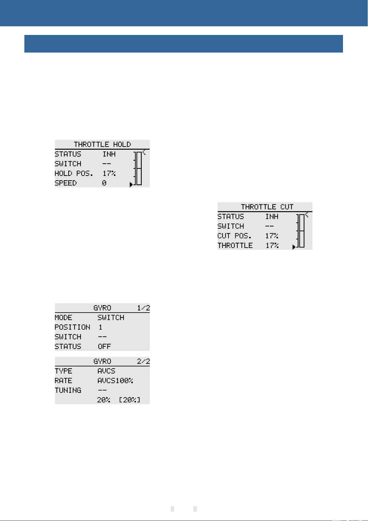
6. Throttle Hold Set ting
From the [MODEL MENU] , call t he [THROTTLE
HOLD] function setting in terface, and use the
[FLIGHT MODE] switch t o switc h to the throttle hold
condition interface.
Hold position setting: This f unction is used to set
the working position(ex tingu ish or idle position) of
the servo under the throttl e hold state.
7. The Swash Mixing Controls th e
Interaction of the Ai lerons, Elevators and Paddles
Through the [SWASH MIXIN G] unde r [MODEL
MENU], the mixing ratio of ea ch oper ation of the
aileron, elevator, and pit ch can be a djusted to
ensure that the swash is corr ected u nder each
condition.
9. Gyro Sensitivity Adjust ment and Mode
Switching
In the [GYRO] mixing f uncti on under [MODEL
MENU], you can adjust the gyr o sensi tivity or mode
switching for each condit ion or sw itch position.
● Normal (hover flight): The gyr oscope is the
most sensitive
● Idle 1 / Idle 2 / Throttle Hol d: Gyro s ensitivity is
minimal.
10. Throttle Cut Setti ng
At the end of the flight, there is n o need to change
the position of the throttl e trim, just turn off the
engine by simply turning a fla meout s witch.
Set in the [THROTTLE C UT] fun ction of [MODEL
MENU]. Set the throttle lev er to idle speed and
adjust the rotation posit ion of th e flame
extinguishing servo unt il the da mper can be closed
and the movement is unimped ed.
8. Throttle Mixing Setting
The swash aileron and eleva tor act ion will cause
the engine speed to decreas e. This phe nomenon
can be compensated by [THRO TTLE MIXING]
under [MODEL MENU]. In add ition , the clockwise
and counterclockwise to rque ch anges can be
compensated for when the bo dy rota tes.
*The throttle trigger pos ition c an be set
separately.
21

SYSTEM SETTING
NOTICE
MODEL SELECT
Interface path: HOME/MO N.→ [SYSTEM SETTING] → [MODEL SELECT ]
The ET06 can store 5 sets of mode l data and flexibly edit and process the informat ion of da ta set.
*Example of model sending f uncti on (Requires two same types and same firmw are ver sions remote
controllers ,and with RF op en):
Type
Signs
Models
working
time
Model
number
Model
name
The back item identifies the
currently used model
Select: Select the model to r un, click the “Select” button on the right, and th e selected model on the left
will turn into a green bottom f rame, i ndicating that the model is successfu lly sel ected. The currently running
model (the model indicate d by the gr een box) will be displayed in the main interface .
Rename: You can rename the sele ction ( the box flashes) The model name is nine characters lo ng and
only supports English nam ing. Mo del group.
Copy: The selected model copi es (overwrites) the data of another model to bac k up the mo del data, or to
quickly add and configure mo dels th at are not very different.
Send: Share the selected mo del data. The selected model data is sent to another E T06.
Receive: The location of the se lected model to receive and store model data sha red by an other ET06.
*The model name is with 8 chara cters a nd only supports English naming.
Model selection ex ample ( Switch to the model that needs to be o perat ed):
The selected model become s a blue bo ttom frame. Click the “OK” button of the fiv e-way b utton or touch
the screen to directly clic k on the model, the selected model flashes, and the r ight op eration option pops up.
Pay attention to the model gr oup nam e when copying the model to avoid erroneous oper ations.
The operation of tra nsmit ting the model data by the No. 1 remot e contr oller and receiving the
model data by the No. 2 re mote co ntroller:
● No.1 remote control: Clic k to select the model group data to be shared (such as “ Model 1 ”), select the
“Send” button displayed o n the rig ht interface, click to select “Yes” in th e pop-u p windo w, and the model
group data is waiting to be rec eived .
● No.2 remote control: first ly select the saved model group position, sele ct an uns et model in the left
model list and click, the rig ht inte rface displays the “receive” button , click , and the prompt pop-up window
selects “yes”. The sec ond rem ote control starts receiving model group dat a
* The transmitter order relat ion of “Transmitter"and "Receiver"fun ction : when operate this function. firstly
operate"transmitter "then o perate"receiver"
* Sending and receiving ope ratio n distance should be within 0.5 meters.
The "copy" function, the ta rget
model data is covered by the
reference model data. Ple ase con firm that the
target model data is no longe r neede d and then do
the copy operation.
22

SYSTEM SETTING
NOTICE
MODEL TYPE
Interface path: HOME/MO N. → [SYSTEM
SETTING] → [MODEL TYP E]
Airplanes are available i n 3 main wi ng types and 3
tail types. Helicopters c an be cho sen 2 swash types.
There is a default preset for e ach type of model data
Model type: helicopter, ai rplan e, multicopter
Helicopter swash: H-1, HR 3 (120° ).
Wing Types (Airplane, glider ):
When setting "MODEL TYPE", t he selection interface will
① ② ③
pop up successively to comp lete th e type selection.If you do
not select "ok" to save the ope ration and return to the parent
interface, the changes ar e not sav ed.
- Wing: 1 aileron, 2 ailerons , delta w ing
- Tail: Normal, V-ta il, Ailv ator; normal, winglet
(delta wing).
Save setting: After the type i s selected, click the
“OK” button in the lower righ t corne r to save the
settings.
Example of operation: set ting the model to
helicopter (HR3)
1 Select "MODEL TYPE" to pop up th e model type
list.
2 Select "Helicopter" to br ing up th e swash list.
When the "MODEL TYPE" is
replaced ( the data in curren t
model will be cleare d! ) , the mo del data reset as
factory configuration of t he new mo del. Therefore,
you must confirm that you do not n eed these data,
or use the [MODEL SELECT] fu nctio n to "copy" the
backup of the model data, and t hen do th e
replacement operation . Same as a bove, such as
"SWASH", "Wing Type" and "Tail Type" o perat ion,
the corresponding opera tion wi ll clear and change
the current model data to the d efaul t parameters of
the newly selected type, so i t is necessary to reset
the model function of [SYST EM SETTING] .
3 Select “HR3” to return to the d efault [MODEL
TYPE] interface, and clic k the“OK” button to save
the changes. Finish setti ng!
23

SYSTEM SETTING
NOTICE
TRAINER
Interface Path: HOME/MO N. → [SYSTEM SETTING] → [TRAINER ]
Trainers can assist stud ents in l earning flight skills and improving flight lev els based on their flight
experience and operatio nal lev el. A special trainer line (sold sep arate ly) is required between the trainer
and the trainer to connect. The t rainer must turn on the trainer mode before the tr ainer can be operated.
When the trainer switch is tu rned off , it will return to the trainer transmitt er to control the flight. When the
student machine flight is da ngero us or the deviation is too large,the trai ner can b e switched immediately to
ensure safety
When using the WFT08/09 as a tr ainer, p lease purchase a universal analog patch cord , 3.5mm male to
male audio cable. (The coac hing li ne and audio cable need to be purchased separate ly. Two co res and
three cores are available .)
- Normal: default mode
- Trainer: Control transmi tter;
- Simulator: When the flight i s practiced through the
computer-side simulat or, the RF i s turned off, reducing
power consumption.To exte nd the wo rking hours of the
transmitter;
- Students: Turn off RF transmi ssion ,only the trainer turn
on the Trainer switch can trai ner cha nnel could be
controlled! (Example: The t rainer model has only three
Trainer mode
Simulator mode
channels: aileron, dire ction a nd gyro, so the student can
only control these three ch annel s when the trainer turn on
the trainer switch. )
Trainer Switch: Defaul t [--]
Student mode
*The following trainer functions take the same model as an example.
Trainer Setting:
Mode→ Trainer, choose contr ol swit ch,channel
status→Turn on with dema nd
* The channel defaults to full on , and the visual
model and actual applicat ion are a djusted。
co ntroll ed properly before flying.Make s ure that
th e con nec tor o f the trainer line is inserted firmly
to avoid looseness.
Status: Each channel stat us switch of trainer. Turn on,
students can be controlle d; off, students Uncontrollable
Student Setting:
Mode-Student.
Ma ke sure that all channels of
th e Trainer and student can be
24

SYSTEM SETTINGSYSTEM SETTING
WARNING
DISPLAY
Interface Path: HOME/MO N. → [SYSTEM SETTING] → [DISPLAY]
Adjust the brightness of th e displ ay backlight, the shutdown time, and th e lock sc reen time to adapt to
different environments a nd ener gy saving.
Contrast: sharpness adjustment.
Backlight: brightness value.
Backlight time: system backlight time!
Automatic lock screen time: lock screen after
touching the screen without any operation.
Automatic shutdown time: transmitter shutdown
af ter no operation time
Parameter Value Setting:
Backlight time, default 3 0 secon ds, 15 seconds, 30 seconds, 1 minute, 2 min utes, 5 m inutes, 10 minutes,
never off.
Auto power off time, default o ff, 30 min utes, 40, 50, 60 minutes, off
Automatic lock screen tim e, default off, 15 seconds, 30 seconds, 1 minute, 2 m inute s, 5 minutes, 10
minutes, off
High brightness display will
increase the energy
consumption of the transmitter, which will
affect the working time of the transmitter.
Please pay attention to setting the transmitter
voltage alarm. Pay attention to the batter y level
and avoid low battery.
25

SYSTEM SETTING
USER NAME
Interface path: HOME/MO N.→ [SYSTEM SETTING] → [USER NAME]
The model name can be user-de fined.
26
 Loading...