

Page 1
MR
N.W. : 6.2 KGS
G.W. : 7.0 KGS
Industrial
UL-EF-I56/W-WH05
OWNER'S MANUAL
GUIDE D’UTILISATION
Please write model number here for future reference: /
Veuillez noter le numéro de modèle aux fins de référence ultérieure:
UL_IndustrialWC_FRECAN 9/2/05 9:48 AM Page 1
Page 2
2
UL-EF-I56/W-WH05
1. Installation work and electrical wiring must be done by qualified person(s) in accordance with all applicable codes and standards (ANSI/NFPA 70-1996), including fire-rated construction.
2. Use this unit only in the manner intended by the manufacturer. If you have any questions contact the manufacturer.
3. After making the wire connections, the wires should be spread apart with the grounded conductor and the equipment-grounding conductor on one side of the outlet box and ungrounded conductor on
the other side of the outlet box.
4. Before you begin installing the fan, Switch power off at Service panel and lock service disconnecting means to prevent power from being switched on accidentally. When the service disconnecting
means cannot be locked, securely fasten a prominent warning device, such as a tag, to the service panel.
5. Be cautious! Read all instructions and safety information before installing your new fan. Review the accompanying assembly diagrams.
6. When cutting or drilling into wall or ceiling, do not damage electrical wiring and other hidden utilities.
7. Make sure the installation site you choose allows the fan blades to rotate without any obstructions. Allow a minimum clearance of 10 feet from the floor to the trailing edge of the blade.
8. To reduce the risk of fire, electric shock, or personal injury, this fan must be mounted to an outlet box marked suitable for fan support. And use mounting screws provided with the outlet box.
(Mounting must support at least 35 lbs.)
9. Do not bend blade holders during installation to motor, balancing or during cleaning. Do not insert foreign object between rotating blades.
10. Attach the mounting bracket using only the hardware supplied with the outlet box. Fan is only to be mounted to an outlet box marked “Acceptable for Fan Support”.
11. To reduce the risk of fire or electric shock, do not use this fan with any solid state fan speed control device, or variable speed control.
12. If this unit is to be installed over a tub or shower, it must be marked as appropriate for the application.
13. NEVER place a switch where it can be reached from a tub or shower.
14. The combustion airflow needed for safe operation of fuel-burning equipment may be affected by this unit’s operation. Follow the heating equipment manufacturer’s guideline safety standards such as
those published by the National Fire Protection Association (NFPA), and the American Society for Heating, Refrigeration and Air Conditioning Engineers (ASHRAE) and the local code authorities.
15. Before servicing or cleaning unit, Switch power off at Service panel and lock service disconnecting means to prevent power from being switched on accidentally. When the service disconnecting means
cannot be locked, securely fasten a prominent warning device, such as a tag, to the service panel.
SAFETY TIPS
OBSERVE THE FOLLOWING: READ AND SAVE THESE INSTRUCTIONS
WARNING: TO REDUCE THE RISK OF FIRE, ELECTRIC SHOCK, OR PERSONAL INJURY, MOUNT TO OUTLET BOX MARKED "ACCEPTABLE FOR FAN SUPPORT",
AND USE THE OUTLET SCREWS PROVIDED WITH THE OUTLET BOX. MOST OUTLET BOXES COMMONLY USED FOR THE SUPPORT OF LIGHTING FIXTURES
ARE NOT ACCEPTABLE FOR FAN SUPPORT AND MAY NEED TO BE REPLACED. CONSULT A QUALIFIED ELECTRICIAN IF IN DOUBT.
TOOLS REQUIRED
Phillips Screwdriver Wire Cutters Pliers Step Ladder
UL_IndustrialWC_FRECAN 9/2/05 9:48 AM Page 2
Page 3
3
UL-EF-I56/W-WH05
1. Les travaux d’installation et de pose des canalisations électriques doivent être réalisés par une/des personne(s) qualifiée(s), conformément aux codes et normes applicables (ANSI/NFPA 70-1996),
notamment en matière de construction résistante aux incendies.
2. Cet appareil ne doit être utilisé que comme prévu par le fabricant. Si vous avez des questions, communiquez avec le fabricant.
3. Après avoir branché les fils, ceux-ci doivent être séparés de sorte que le fil de mise à la terre et le fil de mise à la terre de l’équipement se retrouvent d’un côté de la boîte de sortie de courant, et le fil
non mis à la terre se retrouve de l’autre côté de la boîte de sortie de courant.
4. Avant de commencer l’installation du ventilateur, coupez l’alimentation dans le panneau de fusibles et verrouillez le dispositif de sectionnement afin d’éviter que l’alimentation soit accidentellement
rétablie. Lorsqu’il est impossible de verrouiller le dispositif de sectionnement, donnez un avertissement, en apposant une étiquette au panneau de service, par exemple.
5. Attention ! Lisez toutes les instructions et les conseils de sécurité avant d’installer votre nouveau ventilateur. Regardez tous les diagrammes inclus.
6. Lorsque vous faites une entaille ou que vous percez un trou dans un mur ou un plafond, n’endommagez pas les câbles électriques ou les câbles cachés des autres services publics.
7.
Assurez-vous que le site d’installation choisi permettra aux lames du ventilateur de tourner sans obstruction. Assurez-vous que les lames du ventilateur se trouvent à au moins
3,0 mètres (10 pieds) du sol.
8. Afin de réduire les risques d’incendie, d’électrocution et de blessures, ce ventilateur doit être installé à une boîte de sortie de courant pouvant prendre en charge les ventilateurs. Utilisez les vis de
montage fournies avec la boîte de sortie de courant. (Doit supporter au moins 15,8 kg (35 lb.))
9. Ne fléchissez pas les supports de lames pendant l’installation du moteur, l’équilibrage ou le nettoyage. N’insérez pas de corps étrangers entre les lames rotatives.
10. Attachez le support de montage en utilisant uniquement le matériel fourni avec la boîte de sortie de courant. Il faut fixer le ventilateur uniquement à une boîte portant la mention
«Acceptable for Fan Support» (pouvant prendre en charge un ventilateur).
11. Afin de réduire les risques d’incendie ou d’électrocution, n’utilisez pas de dispositif de commande de vitesse de ventilateur ou de commande de vitesse variable à semi-conducteurs.
12. Si ce ventilateur est installé au-dessus d’une baignoire ou d’une douche, assurez-vous qu’il convient à ce genre d’installation.
13. N’INSTALLEZ JAMAIS d’interrupteur près d’une baignoire ou d’une douche.
14. Ce ventilateur peut affecter l’air de combustion nécessaire au fonctionnement sécuritaire de l’équipement de chauffage. Respectez les lignes directrices du fabricant de l’équipement de chauffage,
tels que celles émises par la National Fire Protection Association (NFPA), l’American Society for Heating, Refrigeration and Air Conditioning Engineers (ASHRAE) et celles des administrations locales.
15. Avant de faire réparer ou de nettoyer ce ventilateur, coupez l’alimentation dans le panneau de fusibles et verrouillez le dispositif de sectionnement afin d’éviter que l’alimentation soit
accidentellement rétablie. Lorsqu’il est impossible de verrouiller le dispositif de sectionnement, donnez un avertissement, en apposant une étiquette au panneau de service, par exemple.
PRÉCAUTIONS
PROCÉDEZ COMME SUIT : LISEZ CES INSTRUCTIONS ET GARDEZ-LES
MISE EN GARDE : AFIN DE RÉDUIRE LES RISQUES D'INCENDIE, D'ÉLECTROCUTION OU DE BLESSURES, IL FAUT FIXER LE VENTILATEUR UNIQUEMENT À UNE BOÎTE DE SORTIE DE COURANT
PORTANT LA MENTION «ACCEPTABLE FOR FAN SUPPORT» (POUVANT PRENDRE EN CHARGE UN VENTILATEUR) ET UTILISER LES VIS DE FIXATION FOURNIES AVEC LA BOÎTE DE SORTIE
DE COURANT. LA PLUPART DES BOÎTES DE SORTIE DE COURANT UTILISÉES POUR SUPPORTER DES APPAREILS D'ÉCLAIRAGE, NE CONVIENNENT PAS POUR PRENDRE EN CHARGE
UN VENTILATEUR ET DOIVENT ÊTRE REMPLACÉES. EN CAS DE DOUTE, CONSULTEZ UN ÉLECTRICIEN QUALIFIÉ.
OUTILS NÉCESSAIRES
Tournevis à tête Philips Coupe-fils Pinces Escabeau
UL_IndustrialWC_FRECAN 9/2/05 9:48 AM Page 3
Page 4
4
UL-EF-I56/W-WH05
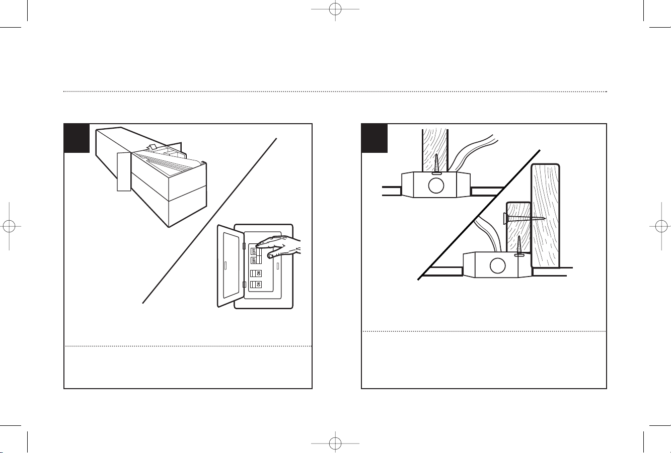
Unpack and inspect fan carefully to be certain all contents are included.
Turn off power at fuse box to avoid possible electrical shock.
1
Use metal outlet box suitable for fan support (must support 35 lbs).
Before attaching fan to outlet box, ensure the outlet box is securely
fastened by at least two points to a structural ceiling member (a loose
box will cause the fan to wobble).
2
PREPARING FOR INSTALLATION
PRÉPARATION À L’INSTALLATION
Déballez le ventilateur. Assurez-vous que toutes les pièces y sont. Mettez
l’interrupteur de la boîte à fusibles sur “OFF” afin d’éviter le risque
d’électrocution.
Utilisez une boîte de sortie de courant en métal pouvant supporter le
ventilateur (doit supporter 15,8 kg (35 lbs)). Avant d’attacher le
ventilateur à la boîte, assurez-vous que la boîte de sortie de courant est
bel et bien fixée à au moins deux points de la structure du plafond. (Si la
boîte n’est pas bien fixée à la structure du plafond, le ventilateur oscillera.)
UL_IndustrialWC_FRECAN 9/2/05 9:48 AM Page 4
Page 5
5
UL-EF-I56/W-WH05
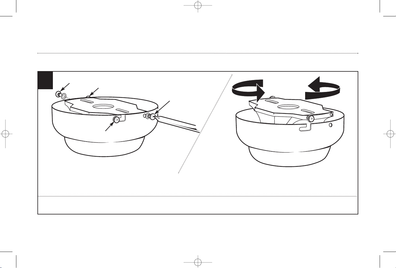
3
Remove the screws and star washers from the two mating holes (1) on the canopy. Loosen (do not remove)the screws in the mating slots (2) on the canopy.
Rotate the mounting bracket counter-clockwise and remove from the canopy.
Retirez les vis et les rondelles étoilées des deux trous d'assemblage (1) se trouvant sur le chapeau. Dévissez (ne pas retirer) les vis des rainures d'assemblage (2) se trouvant sur
le chapeau. Faites tourner le support de montage dans le sens contraire des aiguilles d'une montre et retirez-le du chapeau.
1
2
2
1
MOUNTING BRACKET INSTALLATION
INSTALLATION DU SUPPORT DE MONTAGE
UL_IndustrialWC_FRECAN 9/2/05 9:48 AM Page 5
Page 6
6
UL-EF-I56/W-WH05
5
MOUNTING OPTIONS
OPCIONES DE MONTAJE
Choose a MOUNTING OPTION
Elija una OPCIÓN DE MONTAJE
NORMAL DOWNROD OPTION
If installing downrod supplied with fan, proceed to page 9, step 9.
OPCIÓN CON VARILLA VERTICAL PARA CIELORRASO NORMAL
Si instala la varilla vertical incluida con el ventilador,
proceda a la página 9, paso 9.
EXTENDED DOWNROD OPTION
If installing with longer downrod than supplied with fan, proceed to page 7, step 6.
MONTAGE PAR LA TIGE INFÉRIEURE PLUS LONGUE
Si vous procédez à un montage par la tige inférieure plus longue que celle
fournie avec le ventilateur, passez à la page 7, étape 6.
MOUNTING BRACKET INSTALLATION
INSTALLATION DU SUPPORT DE MONTAGE
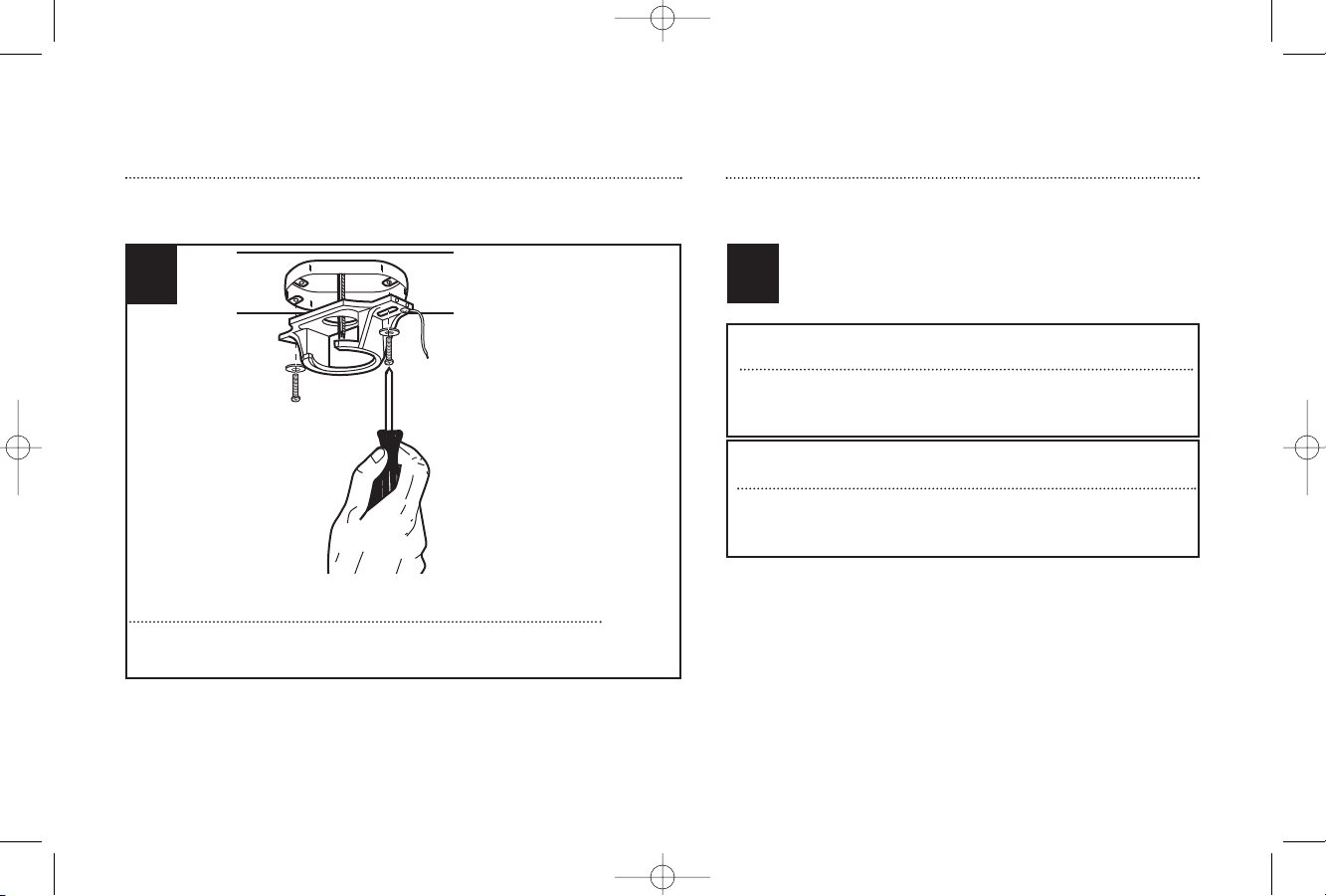
Install mounting bracket to outlet box in ceiling using the screws and
washers provided with the outlet box.
Fixez le support de montage à la boîte de sortie de courant sur le plafond
à l'aide des vis et des rondelles fournis avec la boîte de sortie de courant.
4
UL_IndustrialWC_FRECAN 9/2/05 9:48 AM Page 6
Page 7

6
Loosen downrod ball (1) from downrod (2) by removing set screw (3).
Dévissez la boule (1) de la tige inférieure (2) en retirant la vis
de pression (3).
2
3
1
77
UL-EF-I56/W-WH05
7
Slide downrod ball (1) off of downrod and remove pin (2).
Faites glisser la boule (1) de la tige inférieure et retirez la
tige transversale (2).
2
1
EXTENDED DOWNROD OPTION
MONTAGE PAR LA TIGE INFÉRIEURE PLUS LONGUE
UL_IndustrialWC_FRECAN 9/2/05 9:48 AM Page 7
Page 8

8
UL-EF-I56/W-WH05
EXTENDED DOWNROD OPTION
MONTAGE PAR LA TIGE INFÉRIEURE PLUS LONGUE
8
Re-install pin into extended downrod, and slide downrod ball up to the top of the downrod. Re-install set screw to secure ball to downrod. Note: Some extended downrods
have a pre-drilled set-screw hole. If a pre-drilled hole is present in the extended downrod, tighten the set screw into the pre-drilled hole in the extended downrod. If no
pre-drilled hole exists in the extended downrod, tighten the set screw against the downrod to secure the downrod ball.
Réinstallez la tige transversale sur une tige inférieure plus longue et faites glisser la boule de la tige transversale vers le haut, jusqu’en haut de la tige inférieure.
Réinstallez la vis de pression pour fixer la balle à la tige inférieure. Nota : Certaines tiges inférieures plus longues ont déjà un trou pour la vis de pression. Si la tige
inférieure plus longue a déjà un trou, serrez la vis de pression dans le trou de la tige inférieure plus longue. Si la tige inférieure plus longue n’a pas de trou déjà perforé,
serrez la vis de pression contre la tige inférieure afin de fixer en place la boule de la tige inférieure.
UL_IndustrialWC_FRECAN 9/2/05 9:48 AM Page 8
Page 9

9
UL-EF-I56/W-WH05
9
Loosen set screws on the lower canopy (1). Install canopies onto downrod as
shown. Thread lead wires through the downrod.
Dévissez les vis de pression du chapeau inférieur (1). Installez les chapeaux
sur la tige inférieure comme illustré. Faites passer les fils de connexion par la
tige inférieure en les tournant.
1
Thread leadwires through the downrod and install crosspin (1) through
yoke (2) and downrod. Install lockwasher (3) and nut (4) and tighten.
Install cotter pin (5).
Faites passer les fils de connexion par la tige inférieure et installez la
contre-goupille (1) par la chape (2) et la tige inférieure. Installez la
rondelle de blocage (3) et l’écrou (4) et serrez. Installez la goupille
fendue (5).
10
3
5
4
2
1
UL_IndustrialWC_FRECAN 9/2/05 9:48 AM Page 9
Page 10

10
UL-EF-I56/W-WH05
MOUNTING
MONTAGE
12
2
1
Carefully lift fan assembly onto mounting bracket. Rotate fan until notch
on downrod ball (1) engages the ridge on the mounting bracket (2). This
will allow for hands free wiring.
Avec précaution, soulever l’assemblage de ventilateur jusqu’au support de
montage. Faites tourner le ventilateur jusqu'à ce que l'encoche de la balle
de la tige de suspension (1) s'enclenche dans la saillie (2) du support de
montage. Ceci vous permettra d’effectuer le raccordement des fils sans tenir
le ventilateur.
Loosen set screw in lower canopy and slide to within 1/4” of the motor.
Tighten set screw(s) in the lower canopy. Make sure there is at least 1/4”
clearance maintained around the motor and lower canopy.
Dévissez les vis de pression dans le chapeau inférieur et faites-le glisser à
0,6 cm (1/4") du moteur. Serrez la/les vis de pression dans le chapeau
inférieur. Assurez-vous qu’il y a une distance d’au moins 0,6 cm (1/4")
autour du moteur et du chapeau inférieur.
11
UL_IndustrialWC_FRECAN 9/2/05 9:48 AM Page 10
Page 11

11
UL-EF-I56/W-WH05
MOUNTING
MONTAGE
13
With bracket holding fan assembly, make electrical connections using the
following step for wiring instructions.
Une fois l’assemblage de ventilateur fixé dans le support, effectuez les
raccordements électriques selon l’étape suivante des instructions.
14
White (common)
Black (hot)
Blue* (hot)
Main (ground)
White (common)
Fan Switch (hot)
Light Switch (hot)
Green (ground)
From Fan: From House:
(connect)
(connect)
(connect)
(connect)
*Attach blue wire only if attaching light kit with fan.
Wall Control
Follow diagram above to make wiring connections for wall control operation.
WALL CONTROL WIRING OPTION
Blanc (neutre)
Noir (chargé)
Bleu* (chargé)
Secteur (mise à la terre)
Du Ventilateur: De la Résidence:
(Raccordement)
(Raccordement)
(Raccordement)
(Raccordement)
*Branchez le fil bleu seulement si vous branchez l’ensemble d’éclairage au ventilateur.
Commande murale
Blanc (neutre)
Interrupteur du ventilateur
Interrupteur de l’appareil d’éclairage (chargé)
Vert (mise à la terre)
Afin de raccorder les fils au bloc de connexions de la commande murale,
veuillez suivre le schéma ci-dessus.
OPTION DE RACCORDEMENT DES FILS
POUR COMMANDE MURALE
WIRING OPTIONS
OPTIONS DE RACCORDEMENT DES FILS
UL_IndustrialWC_FRECAN 9/2/05 9:48 AM Page 11
Page 12

12
UL-EF-I56/W-WH05
15
SECURE TO CEILING
ATTACHEZ AU PLAFOND
1
3
2
The canopy has two mating slots (1) and two mating holes (2). Position both slots on canopy directly under and in line with two screws in the mounting bracket (3). Lift
the canopy, allowing the two screws to slide into the mating slots. Rotate the canopy clockwise until both screws from the mounting bracket drop into the slot recesses.
Tighten screws securely. Install two screws and star washers into the mating holes of the canopy and tighten to secure the canopy to the mounting bracket.
Le chapeau est muni des deux rainures (1) et deux trous (2) d'assemblage. Placez les deux rainures du chapeau directement en dessous des deux vis du support de
montage (3) et alignez-les. Soulevez le chapeau de sorte que les deux vis glissent dans les rainures d'assemblage. Faites tourner le chapeau dans le sens des aiguilles
d'une montre jusqu'à ce que les deux vis du support de montage s'encastrent dans la partie la plus mince de la rainure. Serrez les vis fermement. Installez deux vis et
les rondelles étoilées dans les trous d'assemblage du chapeau et vissez-les afin de fixer le chapeau au support de montage.
1
3
2
For flush mount fans, carefully lift fan from the mounting bracket, making sure not to break any wire connections.
For downrod fans, slide the canopy up to the mounting bracket.
Si vous procédez à un montage encastré, soulevez le ventilateur du support de montage avec précaution. Assurez-vous de ne pas endommager les raccordements.
Pour le montage par la tige inférieure, faites glisser le chapeau vers le support de montage.
UL_IndustrialWC_FRECAN 9/2/05 9:48 AM Page 12
Page 13

13
UL-EF-I56/W-WH05
BLADE INSTALLATION
INSTALLATION DES LAMES
Install blades to top of motor using screws and washers . See above
drawing for reference.
Installez les pales sur la partie supérieure du moteur à l’aide des vis et des
rondelles. Voir schéma ci-dessus pour votre référence.
16
UL_IndustrialWC_FRECAN 9/2/05 9:48 AM Page 13
Page 14

14
UL-EF-I56/W-WH05
A. Remove the cross bar screws (2) from the wall control and attach the cross bar(3) to the outlet box.
B. Remove front panel screw (8). Save for use in step E. Remove front cover (7). WARNING: PLEASE USE CAUTION WHEN REMOVING THE FACE PLATE COVER.
C. Connect black supply lead (10) to “A” position, black fan lead wire (11) to “F” position on the terminal box (6), and tighten terminal box screw (9).
D. Re-attach wall control to cross bar (3).
E. Slide front cover (7) over wall control and secure with front panel screw (from step B).
A. Retirez les vis de la barre transversale (2) de la commande murale et attachez la barre transversale (3) à la boîte de sortie de courant.
B. Retirez la vis du panneau de devant (8). Conservez pour l’usage à l’étape E. Retirer le couvercle de devant (7).
MISE EN GARDE : VEUILLEZ PROCÉDER AVEC SOIN LORSQUE VOUS RETIREZ LE COUVERCLE DE PLAQUE AVANT.
C. Branchez le fil d’alimentation noir (10) à la position « A », le fil d’alimentation noir du ventilateur (11) à la position « F » sur la boîte de jonction (6)
et serrez la vis de la boîte de jonction (9).
D. Réinstallez la commande murale sur la barre transversale (3).
E. Faites glisser le couvercle de devant (7) sur la commande murale et fixez bien en place à l’aide de la vis du panneau de devant (conservée lors de l’étape B).
INSTALLING AND WIRING THE WALL CONTROL
INSTALLATION ET CÂBLAGE DE LA COMMANDE MURALE
17
UL_IndustrialWC_FRECAN 9/2/05 9:48 AM Page 14
Page 15

15
UL-EF-I56/W-WH05
INSTALLING AND WIRING THE WALL CONTROL
INSTALLATION ET CÂBLAGE DE LA COMMANDE MURALE
Parts: 1. Outlet box
2. Cross Bar Screws
3. Cross Bar
4. Outlet Box Screws
5. Control Unit
6. Terminal Box
7. Front Panel
8. Front Panel Screw
9. Terminal Box Screw
10. Black Supply Lead Wire
11. Black Fan Lead Wire
12. Ground Lead Wire
Pièces : 1. Boîte de sortie de courant
2. Vis de la barre transversale
3. Barre transversale
4. Vis de la boîte de sortie de courant
5. Bloc de réglage
6. Boîte de connexions
7. Panneau de devant
8. Vis du panneau de devant
9. Vis de la boîte de connexions
10. Fil noir d’alimentation électrique
11. Fil noir du ventilateur
12. Fil de mise à la terre
1
2
3
4
5
7
8
9
6
10
12
11
UL_IndustrialWC_FRECAN 9/2/05 9:48 AM Page 15
Page 16

16
UL-EF-I56/W-WH05
Operation
Turn on the power and check operation of fan. The wall control controls the fan speeds as follows: 0 - Off., 4- High, 3- Med-High, 2- Med, 1- Low. Speed settings depend on factors such as room size,
ceiling height, number of fans and so on.
Maintenance
1. Because of the fan’s natural movement, some connections may become loose. Check the support connections, brackets, and blade attachments twice a year. Make sure they are secure.
2. Clean your fan periodically to help maintain its new appearance over the years. Do not use water when cleaning. This could damage the motor, or the wood, or possibly cause electrical
shock.
3. Use only a soft brush or lint-free cloth to avoid scratching the finish. The plating is sealed with a lacquer coating to minimize discoloration or tarnishing.
4. There is no need to oil your fan. The motor has permanently lubricated bearings.
OPERATION AND MAINTENANCE
TROUBLESHOOTING
If you have difficulty operating your new ceiling fan, it may be the result of incorrect assembly, installation, or wiring. In some cases, these
installation errors may be mistaken for defects. If you experience any faults, please check this Trouble Shooting Chart. If a problem cannot
be remedied, please consult with your authorized electrician and do not attempt any electrical repairs yourself.
TROUBLE
1. If fan does not start:
2. If fan sounds noisy:
3. If fan wobbles:
SUGGESTED REMEDY
1. Check main and branch circuit fuses or circuit breakers.
2. Check wire connections as performed in step #14 or #17 of installation. CAUTION: Make sure main power is turned off.
3. Make sure forward/reverse switch is firmly in up or down position. Fan will not operate when switch is in the middle.
4. If the fan still will not start, contact a qualified electrician. Do not attempt to troubleshoot internal electrical connections yourself.
1. Check to make sure all screws in motor housing are snug (not over tightened).
2. Check to make sure the screws which attach the fan blade holder to the motor are tight.
3. Some fan motors are sensitive to signals from Solid State variable speed controls. DO NOT USE a Solid State variable speed control.
4. Allow “break-in” period of 24 hours. Most noises associated with a new fan will disappear after this period.
All blades are weighed and grouped by weight. Natural woods vary in density which could cause the fan to wobble even though all blades are weight-matched.
The following procedures should eliminate most of the wobble. Check for wobble after each step.
1. Check that all blade holders are tightened securely to motor.
2. Make sure that canopy and mounting bracket are tightened securely to ceiling joist.
3. If blade wobble is still noticeable, interchanging two adjacent (side by side) blades can redistribute the weight and possibly result in smoother operation.
UL_IndustrialWC_FRECAN 9/2/05 9:48 AM Page 16
Page 17

17
UL-EF-I56/W-WH05
Fonctionnement
Mettez le ventilateur en marche et vérifiez-en le fonctionnement. La commande murale commande les vitesses du ventilateur de la façon suivante : 0 – Éteint 4 – Haute vitesse 3 – Moyenne-haute vitesse 2 Moyenne vitesse 1 - Faible vitesse L’utilisation des commandes de vitesse dépend de facteurs comme la dimension de la pièce, la hauteur du plafond, le nombre de ventilateurs, etc.
Entretien
1. Compte tenu du mouvement naturel du ventilateur, il est possible que certains raccordements se desserrent. Vérifiez les raccordements de soutien, les supports et les assemblages de lames deux fois par
année. Assurez-vous qu’ils sont bel et bien fixes.
2. Nettoyez votre ventilateur périodiquement afin de préserver son apparence au fil des années. N’utilisez pas d’eau lorsque vous nettoyez le ventilateur. Ceci pourrait endommager le moteur ou le bois ou
pourrait causer un choc électrique.
3. Utilisez uniquement une brosse à poils doux ou un chiffon non pelucheux afin d’éviter d’égratigner le fini. Le recouvrement est scellé d’un verni afin de réduire au minimum la décoloration ou les ternissures.
4. Il n’est pas nécessaire de lubrifier votre ventilateur. Le moteur est doté de roulements qui sont lubrifiés de façon permanente
FONCTIONNEMENT ET ENTRETIEN
DÉPANNAGE
Si vous éprouvez de la difficulté à faire fonctionner votre nouveau ventilateur de plafond, ceci peut être causé par un assemblage, une installation ou des connexions incorrects.
Dans certains cas, on pourrait méprendre ces erreurs d’installation pour des défauts de fabrication. Si vous éprouvez des difficultés, veuillez consulter le guide de dépannage
suivant. Si vous ne parvenez pas à résoudre le problème, veuillez consulter un électricien qualifié. N’essayez pas de réparer les raccordements électriques vous-même.
PROBLÈME
1. Le ventilateur ne démarre pas :
2. Le ventilateur est bruyant :
3. Le ventilateur oscille :
SUGGESTION
1. Vérifiez les fusibles du circuit primaire et du circuit de dérivation ou les fusibles du disjoncteur.
2. Vérifiez les raccordements électriques effectués à l’étape 14 ou 17 de l’installation. MISE EN GARDE : Assurez-vous que l’alimentation principale est coupée.
3. Assurez-vous que l’interrupteur de marche avant-arrière se trouve sur l’un ou l’autre côté. Le ventilateur ne fonctionne pas lorsque l'interrupteur à glissière se trouve au milieu.
4. Si le ventilateur ne démarre toujours pas, consultez un électricien qualifié. N’essayez pas de réparer les raccordements électriques intérieurs vous-mêmes.
1. Assurez-vous que toutes les vis du caisson du moteur sont bien serrées (mais non excessivement).
2. Assurez-vous que les vis qui relient le support de lames au moteur sont assez serrées.
3. Certains moteurs de ventilateur sont sensibles aux signaux provenant de commandes de vitesses variables à semi-conducteurs. N’UTILISEZ PAS de commande de vitesses
variables à semi-conducteurs.
4. Allouez une période de rodage de 24 heures. La plupart des bruits provenant d’un nouveau ventilateur disparaîtront après cette période de rodage.
Toutes les lames sont pesées et regroupées en fonction de leur poids. Le ventilateur peut toutefois continuer à osciller à cause de la densité inégale du bois naturel. Les
mesures suivantes sont destinées à éliminer la plupart de problèmes d’oscillation. Vérifiez si le ventilateur oscille après chaque étape.
1. Assurez-vous que les supports de lames sont bien fixés au moteur.
2. Assurez-vous que le chapeau et le support de montage sont fermement attachés à la solive de plafond.
3. Si la lame continue à osciller, essayez de substituer une lame pour une autre (lame adjacente) afin de redistribuer le poids et d’assurer un fonctionnement plus uniforme.
UL_IndustrialWC_FRECAN 9/2/05 9:48 AM Page 17
Page 18

18
UL-EF-I56/W-WH05
UL_IndustrialWC_FRECAN 9/2/05 9:48 AM Page 18
Page 19

1
2
3
4
19
UL-EF-I56/W-WH05
PARTS LIST
LISTE DE PIÈCES
# Description
1 . . . . . . . . . . . . . . . . . Mounting Bracket
2 . . . . . . . . . . . . . . . . . Blade
3 . . . . . . . . . . . . . . . . . Wall Control
8 . . . . . . . . . . . . . . . . . Hardware Pack
No Description
1 . . . . . . . . . . . . . . . . .Support de montage
2 . . . . . . . . . . . . . . . . .Lame
3 . . . . . . . . . . . . . . . . .La Commande Murale
8 . . . . . . . . . . . . . . . . .Quincaillerie
UL_IndustrialWC_FRECAN 9/2/05 9:48 AM Page 19
Page 20

UL-EF-I56/W-WH05
Westinghouse Lighting Corporation
12401 McNulty Road
Philadelphia, PA 19154 U.S.A.
Westinghouse Lighting Corporation,
a Westinghouse Electric Corporation licensee
is a registered trademark of
Westinghouse Electric Corporation
Made in China
© 2005
Westinghouse Lighting Corporation
Westinghouse Lighting Corporation
12401 McNulty Road
Philadelphia, PA 19154 U.S.A.
Westinghouse Lighting Corporation,
un fabricant licencié de Westinghouse Electric Corporation
est une marque déposée de :
Westinghouse Electric Corporation
Fabriqué en
China
© 2005
Westinghouse Lighting Corporation
UL_IndustrialWC_FRECAN 9/2/05 9:48 AM Page 20
 Loading...