

Westinghouse WFE946SD, WFE915SD, WFE916DSD User Manual
USER MANUAL
Steam Assist
Clean
Bake/
Pizza
EasyBake
+Steam
90cm COOKING APPLIANCES
WFE904SD, WFE915SD, WFE916DSD, WFE946SD, WFEP917DSD
1IMPORTANT SAFETY INSTRUCTIONS
WARNING
WARNING
TIPS & INFORMATION
ENVIRONMENTAL TIPS
CONTENTSCONGRATULATIONS
Congratulations and thank you for choosing our product.
We are sure you will find your new cooker a pleasure to
use and a great asset to your cooking. Before you use the
appliance, we recommend you read through the whole
user manual which provides a description of the product
and its functions.
To avoid the risks that are always present when you use
an appliance, it is important that the appliance is installed
correctly and that you read the safety instructions
carefully to avoid misuse and hazards. We recommend
that you keep this instruction booklet for future reference
and pass it on to any future owners.
This appliance complies with the requirements
of Australian Standard AS/NZS 60335.2.6.
Gas appliances also comply with the requirements
of AS/NZS 5263.1.1.
Conditions of use
This appliance is intended to be used in household
and similar applications such as:
• Staff kitchen areas in shops, offices and other
working environments
• Farm houses
• By clients in hotels, motels and other residential
type environments
• Bed and breakfast type environments
Please ensure you read the instruction manual fully
before you call for service, or a full service fee could
be applicable.
Important safety instructions ...................................................... 3
Description of your appliance:
WFE904SD ................................................................................. 5
WFE915SD .....................................................................................5
WFE916DSD ..................................................................................5
WFEP917DSD ...............................................................................5
WFE946SD................................................................................... 6
Installation of the appliance ...........................................................7
Wiring requirements ........................................................................17
Installing the freestanding cooker ............................................18
LPG Conversion .................................................................................19
Testing the operation of the gas cooker ...............................20
Before operating your appliance for the first time ........... 21
Installing your oven accessories ...............................................22
Installing burners and trivets ......................................................24
Getting to know your cooktop ..................................................25
Getting to know your ceramic cooktop ................................27
Using your ceramic cooktop ......................................................28
Using your oven ................................................................................ 32
Easybake +steam .............................................................................38
Cooking test .......................................................................................39
Cooking guide .................................................................................. 40
Dealing with cooking problems ................................................43
Cleaning your oven ........................................................................ 44
Cleaning oven accessories ...........................................................45
Steam assisted cleaning ...............................................................47
Cleaning your pyrolytic oven .....................................................48
Troubleshooting ................................................................................49
Warranty ................................................................................................ 51
Record model and serial number here:
Model number:........................................................................................
Serial number: .........................................................................................
PNC: .............................................................................................................
Please read the user manual carefully and store in a handy
place for later reference.
The symbols you will see in this booklet have
these meanings:
WARNING
This symbol indicates information concerning your
personal safety.
CAUTION
This symbol indicates information on how to avoid
damaging the appliance.
IMPORTANT
This symbol indicates tips and information about use
of the appliance.
ENVIRONMENT
This symbol indicates tips and information about
economical and ecological use of the appliance.
2 CONTENTS
WARNING
IMPORTANT SAFETY INSTRUCTIONS
IMPORTANT INFORMATION THAT MAY IMPACT
YOUR MANUFACTURER’S WARRANTY
Adherence to the directions for use in this manual
is extremely important for health and safety.
Failure to strictly adhere to the requirements in
this manual may result in personal injury, property
damage and affect your ability to make a claim
under the Westinghouse manufacturer’s warranty
provided with your product. Products must be
used, installed and operated in accordance with
this manual. You may not be able to claim on the
Westinghouse manufacturer’s warranty in the
event that your product fault is due to failure to
adhere to this manual.
Please read the user manual carefully and store in a
handy place for later reference. Pass the user manual
on to possible new owners of the appliance.
Read the following carefully to avoid damage or injury.
NOTE: You must read these warnings carefully
before installing or using the appliance. If you need
assistance, contact your Customer Care Department.
The manufacturer will not accept liability, should
these instructions or any other safety instructions
incorporated in this book be ignored.
WARNING
General warnings
• This appliance must not be used as a space heater.
• In order to avoid fire, the appliance must be kept clean
and vents kept unobstructed.
• Do not spray aerosols in the vicinity of this appliance
whilst it is in operation.
• Do not use or store flammable materials in this
appliance storage drawer or near this appliance.
• Do not line the bottom of the oven with foil
or cookware.
• Always use gloves when handling hot items inside
the oven.
• Always turn the grill off immediately after use as fat
left behind may catch fire.
• Do not hang any objects from the hob as it may block
the air vents.
• Do not modify this appliance.
• To maintain safe operation, it is recommended that the
product be inspected every 5 years by an authorised
service person.
• Do not install an aftermarket lid or cover over
this appliance.
• The cooking process must be supervised. A short term
cooking process must be supervised continuously.
Installation, cleaning and servicing
• An authorised person must install this appliance.
(Certificate of Compliance to be retained).
• Before using the appliance, ensure that all packing
materials are removed from the appliance.
• In order to avoid any potential hazard, the enclosed
installation instructions must be followed.
• Ensure that all specified vents, openings and
airspaces are not blocked.
• Where the appliance is built into a cabinet,
the cabinet material must be capable of
withstanding 85°C.
• Only authorised personnel should carry out servicing.
(Certificate of Compliance to be retained).
• Always ensure the appliance is switched off before
cleaning or replacing parts.
• Do not use steam cleaners, as this may cause
moisture build up.
• Always clean the appliance immediately after any
food spillage.
• This appliance must be earthed.
• Due to the weight (freestanding 95-100kg) and
size of cookers, 2 persons are required to manually
manoeuvre them. Remove loose items such as trivets,
oven racks and trays to minimise weight.
• Do not use the handle to lift the cooker, instead open
the oven door and lift the roof of the oven cavity.
• Take care when lifting to avoid any sharp edges not
intended for lifting.
• This cooker must not be installed with a cut-off timer.
• Disconnection in the fixed wiring must occur in
accordance with AS/NZS 3000 wiring rules.
3IMPORTANT SAFETY INSTRUCTIONS

WARNING
WARNING
IMPORTANT SAFETY INSTRUCTIONS
WARNING
Oven
• During use the appliance becomes hot. Care should
be taken to avoid touching the hot surfaces inside the
oven.
• Switch the appliance off at the isolating switch before
removing the oven light glass for globe replacement.
• To avoid an accident, ensure that oven shelves and
fittings are always inserted into the appliance in
accordance with the instructions.
• Do not use the door as a shelf.
• Do not push down on the open oven door.
• Do not cover the grill insert with foil, as fat left there
may catch fire.
• Always keep the grill dish clean as any fat there may
catch fire.
Gas cooktops
• Do not allow pots to boil dry, as damage to both
pan and cooktop may result.
• Do not operate the cooktop for an extended period of
time without a pot or pan on the burner.
• Do not allow large cookware to overhang the cooktop
onto the adjacent benchtop. This will
cause scorching to the benchtop surface.
• Do not allow cooking pots or pans to intrude into
the area which is close to the controls.
• Ensure burner bodies and trivets are
properly located.
• Unattended cooking with oil or fat on a hob can
be dangerous and result in fire.
• In order to avoid a fire do not store items on the
cooking surface.
Ceramic cooktops
• In order to avoid a fire do not store items on the
cooking surface.
• Do not place heat resistant mats, wire mats or
aluminium foil under pots and pans.
• Do not allow pots to boil dry, as damage to both
pan and cooktop may result.
• Do not use the hotplate as extra bench space or
as a cutting board.
• Do not allow large cookware to overhang the cooktop
onto the adjacent benchtop. This will cause scorching
to the benchtop surface.
• Do not use round bottom woks or similar utensils
which could lead to overheating of the hotplates and
possible damage to the cooking surface.
• Use the stored heat in the hotplate by turning
the control to off before the final few minutes
of cooking.
• Do not slide pans across the surface of the ceramic
glass as it could result in scratching of the surface.
• The ceramic cooktop is not intended to be operated
by means of an external timer or separate remotecontrol system.
• Unattended cooking with oil or fat on a hob can be
dangerous and result in fire.
WARNING
Child safety
• This appliance is not intended for use by persons
(including children) with reduced physical, sensory
or mental capabilities, or lack of experience and
knowledge, unless they have been given supervision
or instruction concerning use of the appliance by a
person responsible for their safety.
• Children should be supervised to ensure that they do
not play with the appliance.
• During use this appliance becomes hot. Care should
be taken to avoid touching hot surfaces, e.g. oven
door, heating elements etc.
• Accessible parts will also become hot when in
use. To avoid burns and scalds children should be
kept away.
• Always turn pan handles to the side or rear to
prevent accidental knocking and to keep out of
reach of children.
4 IMPORTANT SAFETY INSTRUCTIONS
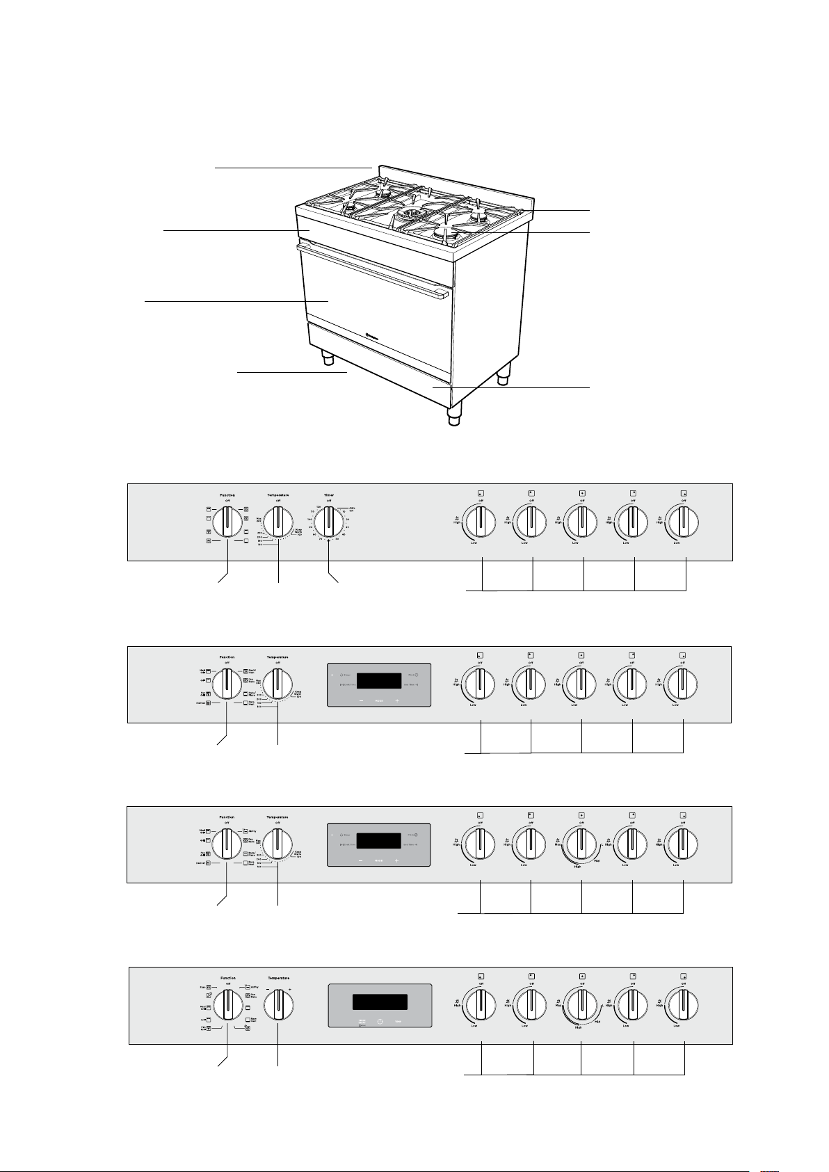
GAS COOKTOP MODELS
Freestanding cooker with flame safeguard gas cooktop and multi-function electric oven
Stainless steel splashback
Control panel
Oven door
Clip on kick panel
(Select model only)
(Refer to Chapter ‘Installation’)
Control Panel
Model WFE904SD
Removable cast iron trivet
Gas hob
(Refer to Chapter ‘Get to know
your cooktop’)
Storage compartment
(Selected model only)
Oven function
selector
Model WFE915SD
Oven function
selector
Model WFE916DSD
Oven function
selector
Model WFEP917DSD
Maxi
Grill
Grill
Fan
Grill
Defrost
Rapid
Heat
Fan
Bake
Bake/
Pizza
Base
Heat
Oven/Grill
temperature
control
Oven/Grill
temperature
control
Oven/Grill
temperature
control
Timer
control
Gas hob
burner
controls
Gas hob
burner
controls
Gas hob
burner
controls
Steam Assist
Clean
Oven function
selector
Bake/
Pizza
EasyBake
+Steam
Oven/Grill
temperature
control
Gas hob
burner
controls
5GAS COOKTOP MODELS

CERAMIC COOKTOP MODELS
Freestanding cooker with electric ceramic hob and multi-function electric oven
Stainless steel splashback
Oven control panel
Oven door
Hob element controls
Ceramic glass hob (Refer
to Chapter‘Get to know
your ceramic cooktop’)
Clip on kick panel included
Control Panel
Model WFE946SD
Oven function
selector
Oven/Grill
temperature control
Storage compartment
6 CERAMIC COOKTOP MODELS
WARNING
INSTALLATION OF THE APPLIANCE
Cabinet requirement
Models WFE904SD, WFE915SD, WFE916DSD,
WFEP917DSD & WFE946SD are designed to fit into a
900mm wide gap between standard kitchen cabinets.
The appliance integrates with the kitchen cabinets by
matching the height, depth and kick panel. The cooker
may also be installed at the end of a line of benches
or with a free space either side. In addition, a slot-in
type installation is catered for allowing a continuous
cabinetry kick panel to be used.
WARNING
• The cooker must be installed and serviced only
by an authorised person.
• A Certificate of Compliance MUST be supplied to
be kept by the customer.
• The packing materials must be removed before
you install the cooker.
• The surrounding kitchen cabinets must be able
to withstand 85°C. Electrolux WILL NOT accept
responsibility for damage caused by installation
into kitchen cabinets which cannot withstand 85°C.
• The pipes used for installation MUST have sufficient
loops so the cooker can be moved for service
(gas models).
• The vents, openings and air spaces MUST NOT
be blocked.
• Two anti-tilt brackets are supplied and stored in the
base of the packaging
• The anti-tilt brackets and chain or front stops
MUST be installed to avoid accidental tipping
(freestanding and slot-in models).
• You MUST NOT lift or pull the cooker by the
door handle.
• The cooker MUST be checked every five years.
• If the supply cord is damaged,it must be replaced
by the manufacturer, its service agent or similarly
qualified persons in order to avoid a hazard.
• The appliance must not be installed behind a
decorative door in order to avoid overheating.
• Due to the weight (95-100kg) and size of the
cooker, 2 persons are required to install it.
• Clearances to combustible surfaces may be reduced
if combustible surfaces are protected in accordance
with clause 6.10.1.2 of AS/NZS 5601.1, or clause 6.9.2
of AS/NZS 5601.2.
• When setting the cooker height, ensure the top of
the cooker is at least 10mm higher than the level of
the benchtop.
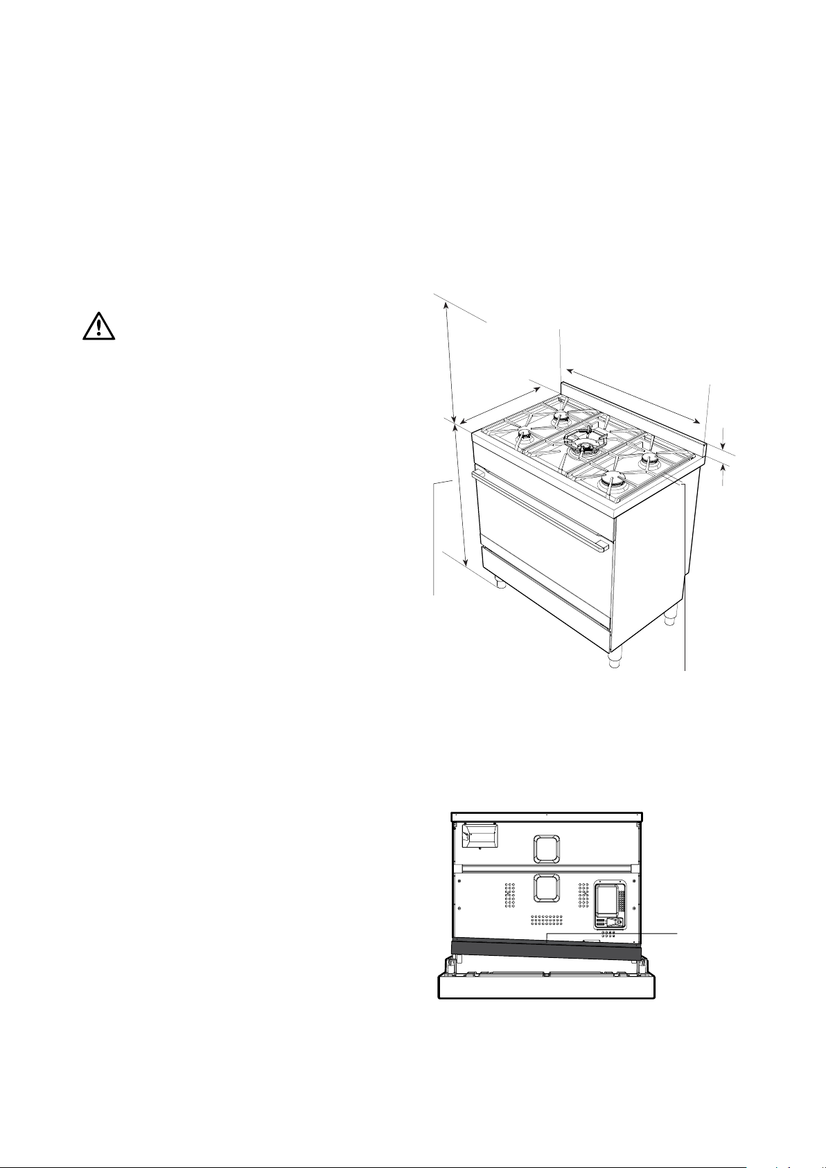
Dimensions
600mm minimum
vertical clearance
from combustible
surfaces
895mm
600mm
60mm
Gas hob 910mm
(adjustable 910-930mm)
Ceramic hob 906mm
(adjustable 906-926mm)
(height of trivet above hob)
15mm
Splashback
The splashback is secured to the back of the cooker.
REMOVE the splashback before installing the feet.
Gas model clearance requirements
• Ensure the appliance is installed in accordance with
clauses 6.2.5 and 6.10.1.1 of AS/NZS 5601.1 or clauses
6.9.1 and 6.9.5 of AS/NZS 5601.2 with regard to
clearances to combustible surfaces and materials,
and clearances to rangehoods and exhaust fans,
to ensure clearances of 200mm from burners to
vertical combustible surfaces observe the minimum
dimension of 100mm from each side of the cooker to
combustible surfaces.
Undo this screw
to remove the
splashback.
Re-attach the
screw afterwards
7INSTALLATION OF THE APPLIANCE

INSTALLATION OF THE APPLIANCE (CONTINUED)
Freestanding installation
The freestanding type installation requires four screw-in
feet to be installed before it can be fitted in between
cabinets, with cabinets on one side or without adjacent
cabinets. There is no clearance requirement to adjacent
side cabinets.
To ensure cooker stability, the anti-tilt brackets must
be installed.
Four screw-in feet are supplied with the appliance and
can be found in the accessories pack in the oven.
WFE915SD, WFE916DSD, WFE946SD & WFEP917DSD
are supplied with a clip-on kick panel.
Cabinet construction for freestanding installation
600mm
both sides
900mm minimum
755mm NOM
900mm NOM
8 INSTALLATION OF THE APPLIANCE

Freestanding installation (continued)
TIPS & INFORMATION
Locking tab up at normal position.
WARNING
WARNING
Installation of screw-in feet
• Freestanding appliance are supplied with four
screw-in feet in the internal accessory pack.
The screw-in feet can be adjusted by turning the
lower half clockwise or anti-clockwise.
IMPORTANT
• WFE904SD is supplied with two silver feet and
two black feet, it is recommended to install the two
sliver feet at the front of the appliance for the best
aesthetics.
• If the appliance is a gas hob model, remove the
burner cap and burner crown. Store all items safely,
away from the installation area.
Gently close the door until it comes to a stop. Then lift
the door off the hinge.
Tilt and carefully lay the appliance on its back to gain
access to the installation point for the screw in feet.
CAUTION
• To avoid scratching the floor and the appliance
itself, fold the packaging carton board and place
it underneath the appliance as protection.
• The cooker MUST be laid on its back when
installing the feet.
You MUST remove the oven door before commencing
installation
Locking tab up at normal position
Press the locking tab down for removing the door.
Put the oven door handle protection
foam underneath the laid down cooker to
protect your cooker when puting it upright
Install the four supplied feet via the four installation
points. Make sure that each foot is securely fastened.
CAUTION
Do not over-torque the foot.
Adjust the height of the screw-in feet to make sure the
hob surface is 10mm above the bench when appliance
is upright.
9INSTALLATION OF THE APPLIANCE

For a 900mm height kitchen bench top,
adjust the lower half of the feet to measure
50mm as shown in the illustration.
WARNING
INSTALLATION OF THE APPLIANCE (CONTINUED)
Bench height + 10mm minimum
If your kitchen has a 900mm height kitchen bench
top, follow the quick measurement guide below before
putting the cooker upright
Leveling oven
Place a level in the oven as below making sure the
level sits on the front and rear forms. Adjust the feet
accordingly to level the appliance.
Installing splashback
50mm
Tilt the appliance upright by lifting the back of the hob
and pivoting it about the back two feet.
WARNING
Heavy item! This step must be performed by two
persons.
Fit splashback to rear of hob with three screws provided.
10 INSTALLATION OF THE APPLIANCE
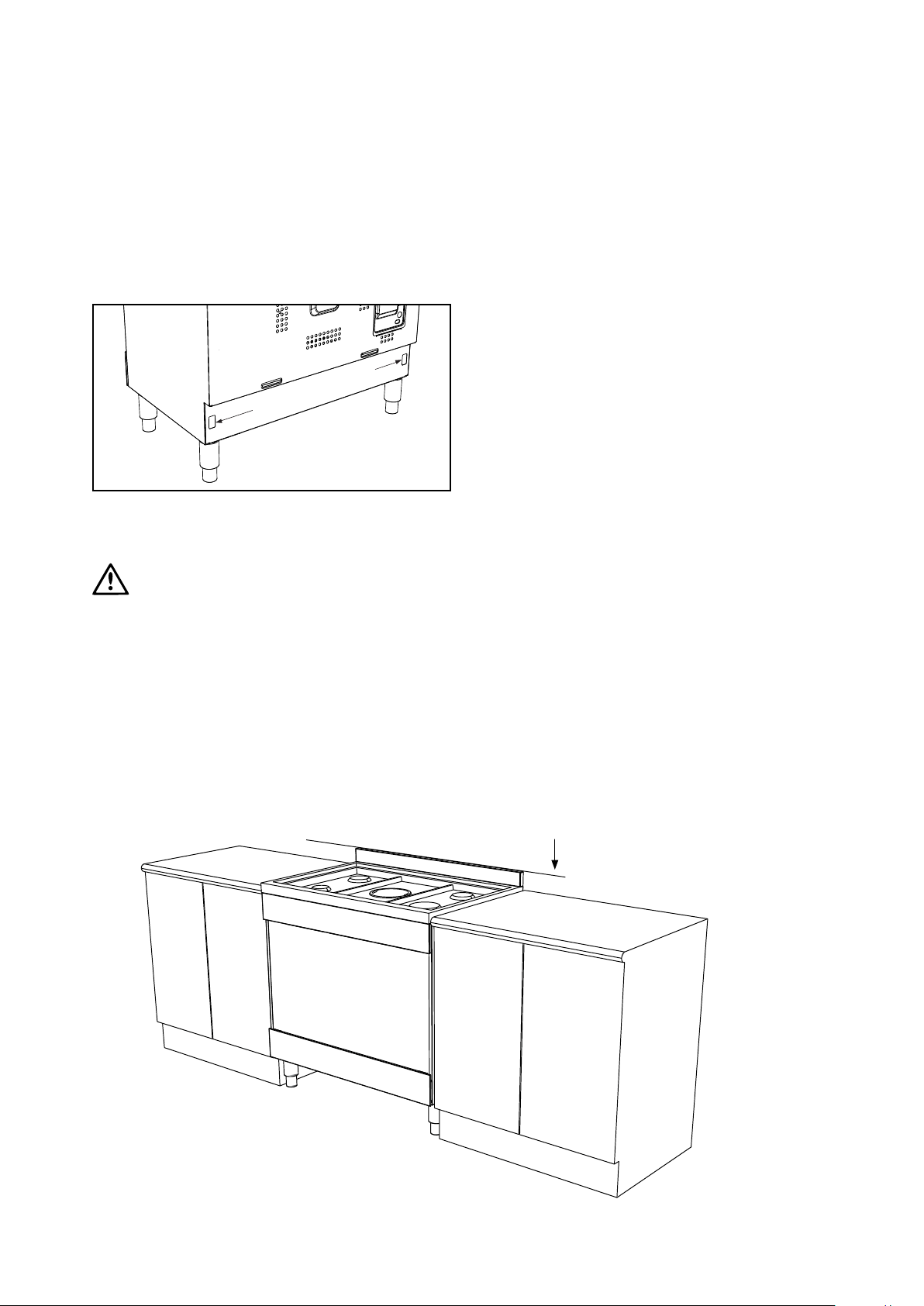
Freestanding installation (continued)
WARNING
Installation the anti-tilt brackets
To ensure cooker stability, the anti-tilt brackets must
be installed.
There are left and right engagement slots for the
anti-tilt bracket at the bottom rear of the appliance.
Anti-tilt bracket
engagement slots
The following steps must be followed to ensure the
correct installation of anti-tilt brackets and the stability
of the appliances.
CAUTION
It is not recommended to push and pull the appliance
on uneven or rough surface. Use other means to
maneuver the appliance if necessary.
1. Carefully push the appliance into the cabinet cavity
until the back of the oven is flush against the back wall.
2. Use non-permanent methods to mark a line on the
wall along the top surface of the splashback. This line
is used as a reference line to locate the correct location
of where the anti-tilt brackets need to be installed.
3. After the reference line is marked, pull the appliance
out of the cabinet cavity to install the anti-tilt brackets.
Anti-tilt bracket
installation
reference line
11INSTALLATION OF THE APPLIANCE
WARNING
INSTALLATION OF THE APPLIANCE (CONTINUED)
Freestanding installation (continued)
WARNING
• Appropriate fasteners must be used to suit the type
of wall on which the anti-tilt brackets are installed.
• Freestanding unit must be pushed up against
the wall on installation. On gas units check that
the gas hose, if used, has not been kinked during
installation.
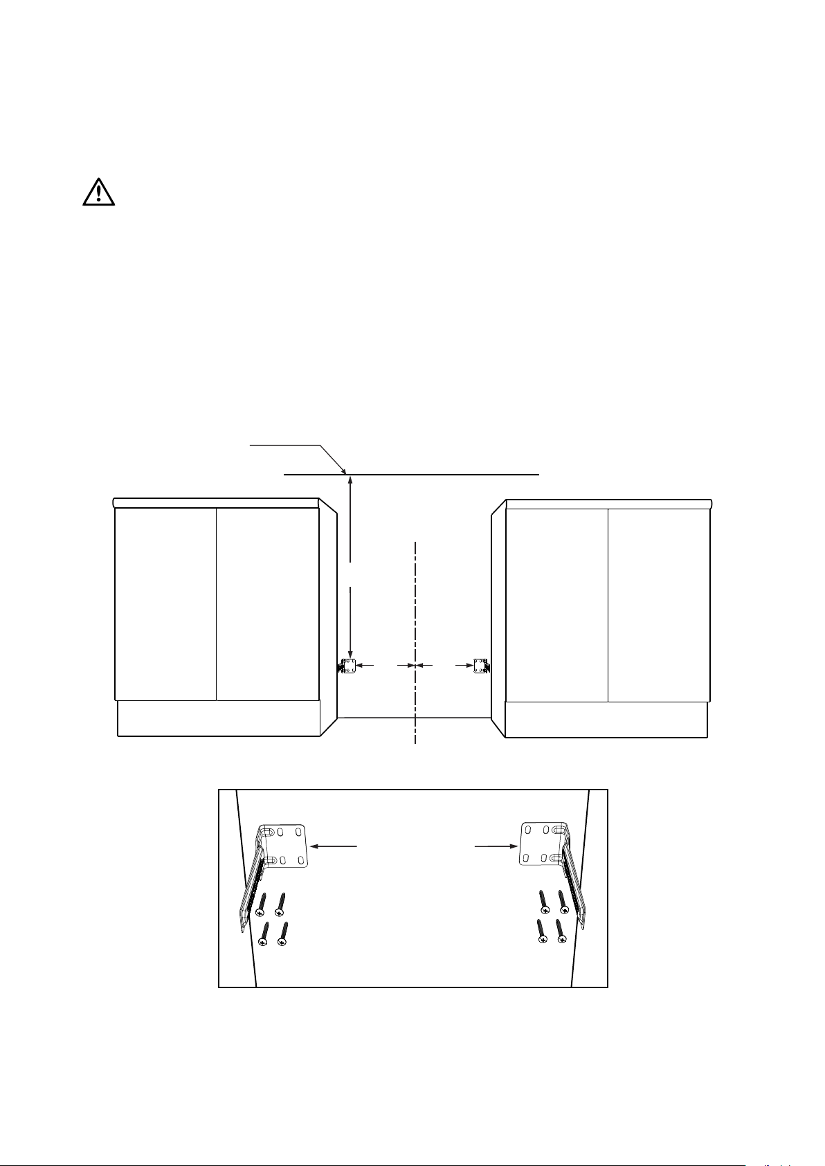
4. The anti-tilt brackets must be secured to the
rear wall of the cavity with appropriate fasteners
according to dimensions in diagram.
Anti-tilt bracket
installation
reference line
C
L
425
725
370 370
Install anti-tilt brackets
in this orientation as
shown (fasteners not
supplied)
12 INSTALLATION OF THE APPLIANCE
Freestanding installation (continued)
• Connect services to the appliance prior to placing
into cavity.
• To locate appliance, slide into cavity ensuring the
anti-tilt brackets fully engaged with the rear left and
right engagement slots.
• The unit must be pushed against the wall
on installation.
• Re-install oven door, burner body, burner caps and
trivets after the appliance is placed in the cavity.
• Gas only: check that the gas hose, if used, has not
been kinked during installation.
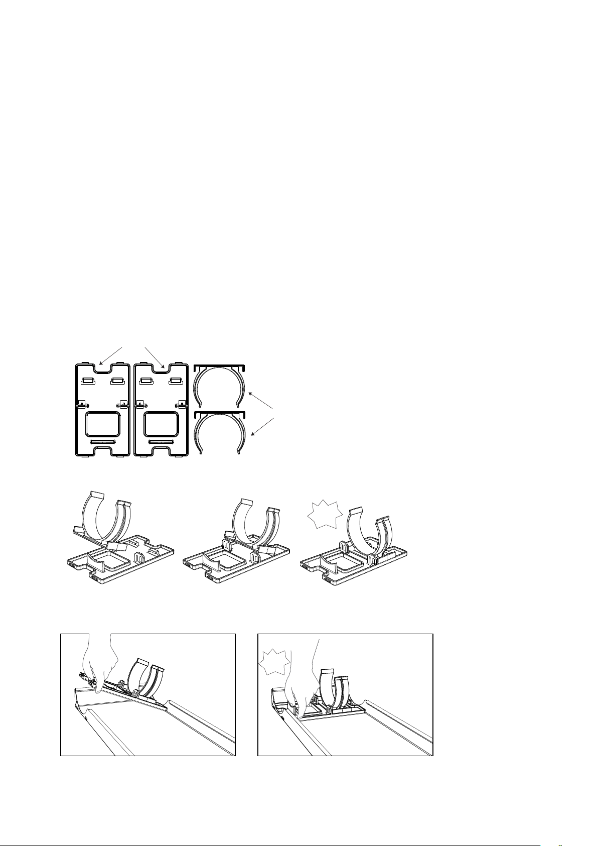
Installing the clip-on kick panel
Models WFE915SD, WFE916DSD, WFE946SD &
WFEP917DSD are supplied with a clip-on kick panel
that can be assembled to clip onto the front feet for a
more integrated and seamless kitchen appearance.
Clip base
Assemble the clip snap onto the base.
Press in both assembled clip modules into the
kick panel in the orientation as shown below.
Clip snap
click!
click!
13INSTALLATION OF THE APPLIANCE

INSTALLATION OF THE APPLIANCE (CONTINUED)
Freestanding installation (continued)
Make sure both clip modules are in the same orientation
after installation.
Clip the kick panel onto the front feet of the appliance.
Make sure the kick panel snaps onto the larger section
of the front feet.
14 INSTALLATION OF THE APPLIANCE
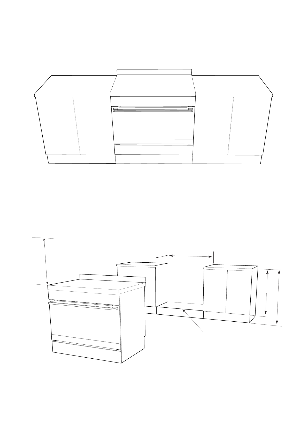
Slot-in installation
The slot-in type installation use the appliance as
supplied. The appliance can be mounted on a plinth.
This enables a continuous cupboard kickboard to be
installed, giving a more integrated appearance. There is
no clearance requirement between oven and adjacent
side cabinets.
600mm minimum
vertical clearance
from combustible
surfaces
600mm
900mm
minimum
This surface to be level with
the top edge of the kick board
755mm
900mm
15INSTALLATION OF THE APPLIANCE

INSTALLATION OF THE APPLIANCE (CONTINUED)
Slot-in installation (continued)
• The anti-tilt brackets are to be secured to the back
wall with appropriate fasteners.
• Two stops are to be screwed to the plinth in
locations as shown (stops provided). The stops
locate into slots in the base of the appliance to
prevent the product from being pulled forward
when installed.
• Measurements from the rear wall are to be adjusted
if there are tiles etc. that come between the
appliance and the wall.
C
L
104 104
370 370
165 165
344
Location of holes
for front stops
344
• Once services are connected, product can be lifted
onto the plinth and pushed back carefully, ensuring
the appliance engages into both brackets at the rear
and the front stops.
• If the product requires removal for service, it must
be lifted at the front approximately 5mm to clear the
front stops prior to being pulled forward.
+
+
+
+
+
+
+
+
+
+
Measurements are to be adjusted to account for the thickness of any skirting
board or tiles coming between the back of the appliance and the wall
Front stops
Front stops
16 INSTALLATION OF THE APPLIANCE
 Loading...