

Page 1

SE 6000
SE 6000
S
ECURITY
M
ANAGEMENT
S
YSTEM
STANDARD
PRODUCT
MANUAL
Westinghouse
Security Electronics
an ISO 9001 certified company
5452 Betsy Ross Drive
Santa Clara, CA 95054-1184
(408) 727-5170
FAX (408) 727-6707
P/N 66107919001, Rev. F
Page 2

LIMITED WARRANTY
Westinghouse Security Electronics (WSE) warrants to the original user the equipment manufactured by WSE as
described herein (the equipment) to be free from defects in material and workmanship for a period of one year from
the date of purchase by such user or fifteen (15) months from the date of shipment from the factory, whichever
is sooner, provided:
I WSE has been notified within such period by return of any alleged defective equipment, free and clear
of any liens and encumbrances to WSE or its authorized Dealer at the address specified, transportation
prepaid; and
II the equipment has not been abused, misused or improperly maintained and/or repaired during such
period; and
III such defect has not been caused by ordinary wear and tear; and
IV such defect is not a result of voltage surges/brownouts, lightning, water damage/flooding, fire, explosion,
earthquakes, tornadoes, acts of aggression/war or similar phenomena; and
V accessories used as an integral to WSE systems have been approved by WSE (e.g., coaxial cables,
batteries, etc.); and
VI the equipment has been installed, the installation supervised or installation tested by an authorized WSE
dealer.
WSE's Proximity Command Keys are warranted for 5 years. WSE shall at its option, either repair or replace, free
of charge, the equipment found, upon WSE's inspection to be so defective, or if agreed upon, refund the purchase
price, less a reasonable allowance for depreciation, in exchange for the equipment. Magnetic Stripe Cards are
warranted as described by the manufacturer's warranty.
WSE makes no other warranty, and all implied warranties including any warranty of merchantability or fitness for
a particular purpose are limited to the duration of the expressed warranty period as set forth above.
WSE's maximum liability hereunder is limited to the purchase price of the equipment. In no event shall WSE be
liable for any consequential, indirect, incidental or special damages of any nature arising from the sale or use of
the product.
Some states do not allow limitations on incidental or consequential damages or how long an implied warranty lasts,
so the above limitations may not apply. This warranty gives specific legal rights; however, other rights which vary
from state to state, may pertain.
IMPORTANT
The information provided in this manual is believed to be accurate and reliable. However, Westinghouse Security
Electronics (WSE) assumes no responsibility for any errors that may appear. Possession of this manual does not
imply the granting of licenses to make or sell equipment or software constructed according to descriptions
provide
d.
© 1997 Westinghouse Security Electronics
All rights reserved. Printed in the United States of America.
Page 3

TABLE OF CONTENTS
SECTION 1: INTRODUCTION .................................................... 1-1
MANUAL ORGANIZATION ............................................................................... 1-1
System Main Menu ..................................................................................... 1-1
Documentation Methods ............................................................................. 1-2
DEFINITIONS ................................................................................................... 1-2
General .......................................................................................................1-2
System Hardware — Devices ..................................................................... 1-3
System Software .........................................................................................1-5
Principal System Functions ......................................................................... 1-6
SAMPLE SYSTEM ............................................................................................ 1-7
CREATING THE DATABASE ............................................................................ 1-8
BASIC SYSTEM USAGE .................................................................................. 1-9
Logging On ................................................................................................. 1-9
System Screens ........................................................................................ 1-10
Application Screens .................................................................................. 1-10
SCREEN EXAMPLES ..................................................................................... 1-11
USING SCREENS AND FIELDS ..................................................................... 1-12
Selecting Screens ..................................................................................... 1-12
Moving Between Data Fields ..................................................................... 1-12
Moving to Prior Screens ............................................................................ 1-13
FINDING, ADDING, AND STORING DATA ..................................................... 1-13
Finding Data .............................................................................................. 1-13
Searching With Partial Information ............................................................ 1-13
Adding / Changing Data ............................................................................ 1-14
Storing Data .............................................................................................. 1-14
DELETING RECORDS ................................................................................... 1-14
ZOOM FEATURE ............................................................................................ 1-15
Cancel Zoom ............................................................................................ 1-15
MISCELLANEOUS INFORMATION ................................................................ 1-15
LOGGING OFF ............................................................................................... 1-15
SHUTTING DOWN ......................................................................................... 1-16
RESTARTING ................................................................................................. 1-16
Automatic Restart ..................................................................................... 1-16
Manual Restart.......................................................................................... 1-16
SYSTEM SCREEN TREES ............................................................................. 1-17
Appendix A: System Screen Trees ........................................................... 1-17
Appendix B: System Screen Hierarchies................................................... 1-17
OPTIONAL FEATURES .................................................................................. 1-17
iii
SECTION 2: MONITOR SECURITY ACTIVITY .......................... 2-1
INTRODUCTION ............................................................................................... 2-1
SECTION ORGANIZATION .............................................................................. 2-1
FUNCTION KEYS ............................................................................................. 2-2
DATA ITEM SELECTION .................................................................................. 2-2
CONTROL FUNCTIONS MENU ....................................................................... 2-2
Pollers ......................................................................................................... 2-2
Devices .......................................................................................................2-3
Locks .......................................................................................................... 2-4
Input Points ................................................................................................. 2-5
Output Points .............................................................................................. 2-5
Page 4

iv
Doors .......................................................................................................... 2-6
Select Zone ................................................................................................. 2-6
REVIEW TRANSACTIONS (FULL SCREEN) ................................................... 2-7
ALARM SERVICING ......................................................................................... 2-8
REAL TIME CONTROL MAPS .......................................................................... 2-8
CONTROL PROJECTS .................................................................................... 2-9
ABORT TIMERS ............................................................................................... 2-9
OTHER FUNCTIONS ........................................................................................ 2-9
Printer Control .............................................................................................2-9
Forgive Passback ..................................................................................... 2-10
Manual Access Granted ............................................................................ 2-10
Force Table Download .............................................................................. 2-10
Remote Devices ....................................................................................... 2-11
Building Modes ......................................................................................... 2-11
Full Screen Monitoring .............................................................................. 2-12
MISCELLANEOUS INFORMATION ................................................................ 2-12
Disk Almost Full Warning .......................................................................... 2-12
Status Screen Function Timeout ...............................................................2-13
Alarm Servicing — No Activity Timeout ..................................................... 2-13
Monitoring Security - Passwords ............................................................... 2-14
Modified Usage of Invalid Facility Code Log .............................................. 2-15
SECTION 3 SECURITY REPORTS ............................................ 3-1
INTRODUCTION ............................................................................................... 3-1
POINT HISTORY REPORT............................................................................... 3-2
Point History — Sample Report .................................................................. 3-2
KEYHOLDER HISTORY REPORT.................................................................... 3-2
Keyholder History — Sample Report ........................................................... 3-3
TRANSACTION HISTORY REPORT ................................................................ 3-3
Transaction History — Sample Report ........................................................3-4
ACCESS CONTROL ARCHIVE REPORT ........................................................ 3-4
ALARM SERVICING REPORT ......................................................................... 3-4
Alarm Servicing — Sample Report.............................................................. 3-5
PASSBACK ZONE REPORT ............................................................................ 3-5
Passback Zone — Sample Report .............................................................. 3-6
DOWNLOAD STATUS REPORT ...................................................................... 3-6
Download Status — Sample Report ............................................................ 3-7
KEYHOLDER ZONE REPORT ......................................................................... 3-8
Keyholder Zone — Sample Report ............................................................. 3-8
EVENT / POINT REPORT ................................................................................ 3-8
Event / Point — Sample Report .................................................................. 3-9
REALTIME PASSBACK ZONE REPORT .......................................................... 3-9
REALTIME PASSBACK DETAIL — SAMPLE REPORT.................................. 3-10
SECTION 4 MASTER FILE ENTRY............................................ 4-1
INTRODUCTION ............................................................................................... 4-1
Screen Access ............................................................................................ 4-1
KEYHOLDERS .................................................................................................. 4-2
Keyholder Entry—Page 1 [key_entr] ........................................................... 4-2
Keyholder Entry—Page 2 [key1entr] ........................................................... 4-4
Page 5

Keyholder Access Entry [empgentr] ............................................................ 4-5
Project Assignment [epj_entr] ..................................................................... 4-6
COPY KEYHOLDERS ....................................................................................... 4-7
Copy Keyholder Information ........................................................................ 4-7
ACCESS ASSIGNMENT ................................................................................... 4-8
Keyholder Access Assignment [egrpentr] ................................................... 4-8
COPY KEYHOLDER ACCESS [ERGCOPY] ..................................................... 4-8
ACCESS DEFINITION ...................................................................................... 4-9
Access Code Entry [acdsentr] .....................................................................4-9
Access Group Entry [agdsentr], [agrpentr] ................................................ 4-11
Access Override Entry .............................................................................. 4-13
Failsoft Entry ............................................................................................. 4-14
Project Entry [prj_entr], [prd_entr] ............................................................. 4-14
TIME CODES [TMCDENTR] ........................................................................... 4-16
HOLIDAYS [HOL_ENTR] ................................................................................ 4-16
TENANTS [TENTENTR] ................................................................................. 4-17
INSTRUCTIONS [INSTENTR] ........................................................................ 4-17
HARDWARE CONFIGURATION [CONFMENU] ............................................. 4-18
Zones [zoneentr] ....................................................................................... 4-18
Areas [areaentr], [areaentr1] ..................................................................... 4-19
Pollers [pol_entr] ....................................................................................... 4-19
Devices .....................................................................................................4-21
Device Entry [dev_entr] — All Device Types ............................................. 4-22
SE NexSentry Device Configuration Entry [nexsentr] ................................ 4-26
Readers .................................................................................................... 4-31
Reader Entry [rdr_entr] ............................................................................. 4-32
Points [pnt_entr] ........................................................................................ 4-39
Auto Opens / Activates.............................................................................. 4-42
Device Report Definition [rdefentr] ............................................................ 4-43
SE 422 PIN Definition ............................................................................... 4-43
SE 422 Hardware Definition ...................................................................... 4-44
Dialer Entry ............................................................................................... 4-45
Site Entry Definition ................................................................................... 4-46
ABA Configuration Entry ........................................................................... 4-47
DKR Configuration Entry ........................................................................... 4-48
USER-DEFINED INFORMATION .................................................................... 4-49
MAPS .............................................................................................................. 4-50
Map Drawing Commands and Descriptions .............................................. 4-50
v
SECTION 5: MASTER FILE REPORTS ..................................... 5-1
INTRODUCTION ............................................................................................... 5-1
ADDITIONAL INFORMATION ........................................................................... 5-2
KEYS MASTER .................................................................................................5-2
Keyholder Quick List — Sample Report ......................................................5-3
Keyholder Holder Master Report — Sample Report .................................... 5-3
ACCESS ASSIGNMENTS ................................................................................. 5-4
Keyholder Access Assignment .................................................................... 5-4
Keyholder Access Assignment: Regular — Sample Report ........................ 5-4
Keyholder Access Assignment: Extended — Sample Report...................... 5-5
Page 6

vi
Reader Access Assignment ........................................................................5-5
Reader Assignment — Sample Report ....................................................... 5-5
ACCESS DEFINITION ...................................................................................... 5-6
Access Code Master ................................................................................... 5-6
Access Group Master ................................................................................. 5-6
Access Override ......................................................................................... 5-7
Intelligent Fail Soft Report ........................................................................... 5-7
Project Report .............................................................................................5-8
Keyholder Project Report ............................................................................ 5-9
Reader Project Report .............................................................................. 5-10
TIME CODES .................................................................................................. 5-10
HOLIDAYS ...................................................................................................... 5-11
TENANTS ....................................................................................................... 5-11
Tenants — Sample Report ........................................................................ 5-12
COMPANY, DEPT, LOCATION, JOB CAT ....................................................... 5-12
Company, Dept, Location, Job Cat — Sample Company Report .............. 5-12
INSTRUCTIONS ............................................................................................. 5-12
Sample Instructions .................................................................................. 5-13
MAPS .............................................................................................................. 5-13
Sample Report — Map Information ........................................................... 5-13
DEVICE CONFIGURATION REPORTS .......................................................... 5-13
Zones ........................................................................................................ 5-13
Zones — Sample Report .......................................................................... 5-14
Pollers ....................................................................................................... 5-14
Pollers — Sample Report.......................................................................... 5-14
Devices .....................................................................................................5-14
Devices — Sample Report ........................................................................ 5-15
Readers .................................................................................................... 5-15
Readers — Sample Report ....................................................................... 5-16
Points ........................................................................................................ 5-16
Points — Sample Report........................................................................... 5-16
Auto Opens / Activates.............................................................................. 5-17
Auto Open / Activate — Sample Report .................................................... 5-17
808 Report Definition ................................................................................ 5-17
808 Report Definition —Sample Report .................................................... 5-17
808 Device Configuration .......................................................................... 5-18
808 Device Configuration — Sample Report ............................................. 5-18
Dialers ....................................................................................................... 5-18
Dialers — Sample Report ......................................................................... 5-18
Site Definition ............................................................................................ 5-18
Site Definition — Sample Report ............................................................... 5-19
ABA Configuration .................................................................................... 5-19
ABA Configuration — Sample Report ....................................................... 5-19
DKR Configuration .................................................................................... 5-20
DKR Configuration — Sample Report ....................................................... 5-20
SE 422 PIN Master Report ........................................................................ 5-20
SE 422 PIN Master Report — Sample ...................................................... 5-21
132-COLUMN REPORT DISPLAY .................................................................. 5-21
Page 7

vii
SECTION 6: SYSTEM ADMINISTRATION ................................. 6-1
INTRODUCTION ............................................................................................... 6-1
SECTION ORGANIZATION .............................................................................. 6-1
ADDITIONAL INFORMATION ........................................................................... 6-2
ADD USERS [ADDUSERS] ............................................................................... 6-2
MODIFY PASSWORDS [MOD_PASS].............................................................. 6-4
PROGRAM SECURITY [SEC_MENU] .............................................................. 6-5
Program Security Level Entry [pgacentr] ..................................................... 6-5
Program Security Entry Definition [pg1_entr] .............................................. 6-5
Copy Security [mnaccopy]........................................................................... 6-6
Security Master List [pgacrprt]..................................................................... 6-6
DISPLAY ALL VALID LOGINS [SHOWUSER] .................................................. 6-7
DISPLAY CURRENT DATE AND TIME [SHOWDATE] ..................................... 6-7
DISPLAY ALL USERS WHO ARE LOGGED IN [SHOWWHO] ......................... 6-7
PURGE A PENDING REPORT [PURGRPRT] ..................................................6-8
ENABLE TERMINALS FOR GLOBAL BEEPING [BEEPENTR] ....................... 6-8
SYSTEM CONFIGURATION (SYCLMENU)...................................................... 6-8
Control File Maintenance [ctrlentr] .............................................................. 6-8
Events [evenentr] ........................................................................................ 6-9
Tasks [taskentr] ......................................................................................... 6-10
Task Event / Master Report [taskrprt] ........................................................ 6-12
Transactions [tranentr] .............................................................................. 6-12
DATABASE MAINTENANCE [DB_MENU] ...................................................... 6-14
Display Database Statistics [dbstats] ........................................................ 6-14
Perform Backup [bkup] ............................................................................. 6-14
Alarm Transaction Clean Up [alrmcln]....................................................... 6-16
Journal Archive [jourarch] ......................................................................... 6-16
Journal Reporting [jourrprt] ....................................................................... 6-16
Special Journal Reporting [josprprt] .......................................................... 6-16
KEYHOLDER LOADING [LOADMENU] .......................................................... 6-17
ID SECURITY MAINTENANCE [ID_MENU] .................................................... 6-17
ID Security User Entry [ID1_ entr] ............................................................. 6-17
ID Security Group Entry [ID2_ entr] ........................................................... 6-18
ID Security Report [ID1_ rprt] ................................................................... 6-18
MISCELLANEOUS INFORMATION ................................................................ 6-19
Adjustable Baud Rate—708P / 800 Pollers ............................................... 6-19
708P REX Shunt Time Reset .................................................................... 6-19
Key Inventory [invtmenu] ........................................................................... 6-20
Inventory Status Code Menu [statentr] ...................................................... 6-20
Key Inventory Status Code Report [statrprt] .............................................. 6-20
Key Inventory Entry [cdinentr] ................................................................... 6-21
Key Inventory Report [cdinrprt] .................................................................. 6-21
PARKING STICKERS [STKRMENU] ............................................................... 6-22
Parking Sticker Entry [stkrentr] .................................................................. 6-22
Parking Sticker Interactive Display [stkrrprt1] ............................................ 6-22
Parking Sticker Master Report [stkrprt] ..................................................... 6-23
Page 8
SECTION 1: INTRODUCTION 1-1
SECTION 1
INTRODUCTION
MANUAL ORGANIZATION
This manual follows the order of the seven standard product items in the system main menu, with
the Key Inventory and Parking Stickers items merged into the System Administration section:
• Section 2: Monitor Security Activity
• Section 3: Security Management Reports
• Section 4: Master File Entry
• Section 5: Master File Reports
• Section 6: System Administration
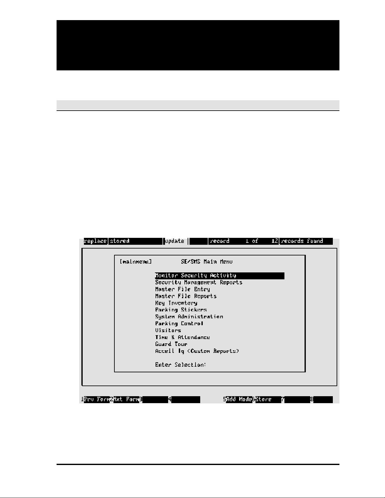
System Main Menu
The system main menu is the departure point for accessing all other system screens (main menu
screens may vary according to options purchased).
Page 9

1-2 SECTION 1: INTRODUCTION
Documentation Methods
To avoid repetition and to reduce document size, detailed explanations for the system's principal
data items are given only in Section 4: Master File Entry, which is used when creating the system
database. For introductory information concerning the data items, see Definitions below.
Further, with the exception of the screens presented in Basic System Usage in this section, and
the introductory menu screens for Sections 2 through Section 5, all other screens throughout this
manual are limited to the particular screen area being discussed (i.e., full screens are not shown).
In some cases, screen presentations are unnecessary and are not used.
DEFINITIONS
General
Access Code. A group of readers and time codes assigned to keyholders indicating where and
when entry is permitted. Note that access codes can be associated with a down loadable device
ID for distributed processing or they can be associated with the host computer for central
processing.
Access Group. A group of access codes created to facilitate the assignment of similar access
privileges to a large number of keyholders.
Alarm Contact. A dry-contact switch, indicating input conditions for smoke detectors, heat /
moisture sensors, taut-wire fences, window bands, etc.
Company. Keyholder's employer.
Department. A particular group within a company to which a keyholder is assigned.
Device. A controlling element of the system which communicates with the computer and the
system points (see System Hardware in this section).
Event. Any defined transaction which requires action by an access control system. Examples:
keyholder entry request, activated alarm.
Job Category. A code assigned to a keyholder indicating the employee group category.
Key Number. Keyholder's security key number. Unlike the keyholder ID, this number may be
changed (e.g., if a key is lost) or removed (e.g., if an employee leaves the company).
Keyholder. Employee or visitor who holds a valid security card for an access control system.
Page 10

SECTION 1: INTRODUCTION 1-3
Keyholder ID. Keyholder's ID number. The unique ID number is used by the computer to keep
track of all activity for that person. Once entered, the keyholder ID cannot be changed.
Location. Location of the office or branch of the company to which a keyholder is assigned.
Tenant. One of several distinct occupants of a facility with a single access control system. The
data for each tenant using the system appears separate from that of all other tenants.
Time Code. A definition of the time of day, and the days of the week, when events are to occur.
Used in assigning access privileges, performing scheduled tasks, and monitoring points.
Trace. A realtime (as it is happening) display of events for a specific keyholder or point.
Transactions. System responses to events are called transactions. The most frequently seen
is A
CCESS GRANTED, which means a valid key was presented to a reader at an approved door, at
an approved time, and that the keyholder was granted entry.
Zones. Selected locations and device types may be grouped into zones to facilitate system
control. For reporting purposes, zones may be grouped into areas. If zones are created, antipassback instructions or controls may be assigned (see Access Control Functions in this section).
System Hardware — Devices
The principal device is the host computer. The host controls all data maintained in the database,
records all system activity, and is the central point for all reporting activity. The host communicates
with all system devices, or may communicate via an LC or RLC computer (see Optional Features
in this section).
Various other devices are included in access control systems. Simple systems may use only
contact switches and a single reader type. More complex systems may use several reader types
and many other devices. Devices are classified as input or output units depending on their
particular function. Input devices are detectors and identifiers; output devices are alarms and
control units.
Devices — Microprocessor Units
Access Control Units (ACUs). In conjunction with the host or local computer, the ACUs are used
to control door access and maintain status. Example ACUs are: WSE NexSentry, 422, 708P,
and 8xx-series. The WSE 708P units are called simple devices because they do not make access
decisions (decisions are made by host). The NexSentry, 422, and 8xx-series units are called
intelligent devices because they can make access decisions independent of the host.
Biometric Hand Readers. Devices such as fingerprint analyzers, hand geometry analyzers,
retina scanners, and other devices which check body characteristics.
Page 11

1-4 SECTION 1: INTRODUCTION
Readers
Digital Key Reader. Reads the unique number of 1 to 5 digital command keys simultaneously
at a range of up to 36 inches.
Keypad Controllers. The keypad controllers, normally used in conjunction with an ACU, provide
additional security by requiring a personal identification number (PIN) entry.
Magnetic Card Readers. Reads the card number from information coded into the magnetic strip
on the card. Card must be moved physically through the reader to work.
Readers (also called Sensors). These units electronically read the security key presented and
transmit the data to the ACU. Three reader types are used: Proximity; Magnetic Stripe; Wiegand.
Inputs
Alarm Contacts. These devices monitor simple contact inputs, and control outputs and switches
with contact closures for alarm monitoring, elevator control, camera switching, and other tasks.
Contact Alarms. Simple dry-contact switches indicating if a contact is open or closed.
Door switches. The computer controls only the lock power to the door, and the door switches
are the contact points which inform the computer whether a specific door is open or closed. Each
door switch is assigned to a specific reader.
Fire Alarms / Heat Sensors. Data from smoke detectors and heat sensors can be sent to the
computer to alert it to alarm conditions. Although fire alarm systems are generally separate from
access control systems, the computer can be used to provide enhanced response capabilities.
Intrusion Devices. Taut wire fence, infrared detectors, field-disturbance detectors and other
device types can alert the computer to the presence of personnel in unauthorized areas.
Motion Sensors. Detect physical movement in an area. Can be used to tell the computer that
someone wants to exit (go through a door from the uncontrolled side), or to protect secure areas.
Video Monitor Switchers. The computer routes the signal from a particular video camera to a
specific monitor based on conditions in that area. For example, if the computer detects an open
rear door, it can display the camera output at that door on the terminal at the security desk.
Page 12

SECTION 1: INTRODUCTION 1-5
Multiple Switch Monitor (MSM). The MSM is a four-contact switch box that is connected to a
WSE ACU and the MSM provides four contact-closure inputs.
Points. A point is any basic element of an access control system, such as a door switch, an alarm
contact, an output switch. Point IDs uniquely identify all system elements.
Request-to-Exit (REX) Sensor. Used when both entry and exit control is required. REX points,
usually push-button devices, motion detectors, or push-bars, tell the computer that someone
inside a building wants to exit. The computer needs to know this to unlock the door, or to disregard
the door opening as being an alarm event.
Outputs
Audible Alarms. The computer can trigger bells, buzzers and other types of audible alarms.
Remote Alarms. The computer can dial police and / or fire departments, or any other agency,
as part of an alarm response plan.
System Software
The system software links all input and output elements. The software collects and reports data
from input devices, and controls the output devices based on this information. The software also
detects and reports any hardware problems that may occur.
Complete Portability. A specific computer type is not required, although Hewlett-Packard
computers are preferred because of performance and worldwide service. Application programs
run under an SCO / UNIX operating system.
Installation Flexibility. The SE 6000 can control many hardware setups, including remote site
networks. The system can be programmed to control data flow between central and remote
computers to create a large-size security system controlled from a central point.
Integrated Software Support. The SE 6000 communicates with a variety of access control and
alarm monitoring devices. Currently, the system interfaces with WSE ACUs and their peripheral
devices, alarm multiplexers produced by Stellar Systems and Optomux, magnetic stripe readers,
CCTV camera switchers made by Burle, Pacom, American Dynamics, and Vicon, Radionics
alarm panels, and Recognition Systems hand geometry readers. In addition, the system supports
communication with the WSE 8xx-series ACUs over dial-up telephone lines using a remote dialup interface (RDI) device. The ID-4000 badging system includes options for badge designs on film
or on PVC.
Open System Design. There are few restrictions on the number of security keys, key readers,
or other system elements used with the SE 6000. Increasing system capacity only involves
upgrading the computer power by adding more memory or disk space, or installing a faster
processor. This means that, as a company grows, it cannot outgrow the SE 6000.
Page 13

1-6 SECTION 1: INTRODUCTION
Response Time. The SE 6000 is capable of fast response times in both single and multiple site
configurations. Fast response times are important for security personnel who monitor alarms and
are always appreciated by keyholders wishing to enter locked doors.
Principal System Functions
Access Control
Anti-Passback Control. The SE 6000 has anti-passback features (applies to zones only) to
prevent tailgating or unauthorized key use. Anti-passback is possible across multiple access
control devices, and can be hard (denies access) or soft (allows access, but displays and logs a
message). The software handles vehicle and personal passback separately.
Automatic Access Control. Permits employees or visitors with assigned access codes to pass
through only those doors assigned to them and only during the proper days and hours.
Automatic Activate / Deactivate. Permits the automatic activation of specific output points to
control lighting, status indicators, or other electrically controlled functions.
Automatic Unlock / Lock. Allows doors to be opened automatically only during specified time
periods, then re-locked automatically at a later time.
Communications Monitor. Permits security personnel to check all wiring and communications
to all hardware elements and displays raw data exchange between the host computer and a
connected device.
Event Monitoring. Displays events as they occur and monitors the door status and other access
points. Allows security personnel to watch events at all doors in the system from one location.
Flexible Event Handling. Flexible event handling automatically activates outputs, displays
special messages, and enables / disables devices. Anything which can be done manually on the
SE 6000 can also be performed automatically using this feature.
Independent PIN Entry. Access control can be enhanced using personal identification numbers
(PINs). PINs are entered via keypad devices assigned to readers. Also, high-security independent
devices (hand geometry readers, e.g.) can identify the user.
Manual Access Control. Allows security personnel to manually open any door in response to an
access request. May be used with closed-circuit TV to verify and admit people, or to track
keyholders who have forgotten their keys. Includes the capability to record keyholder IDs if keys
are not available. All manual actions are logged as events.
Two-Man Rule. The SE 6000 can be programmed to grant access only after two valid key
presentations have been made at the same reader within a predefined period of time.
Page 14

SECTION 1: INTRODUCTION 1-7
Multiple Occupancy Feature. Similar to the two-man rule except that it requires that two
keyholders enter and leave a specified zone together; refer to Section 4 for details.
File Maintenance
To perform its access control functions, the system must know the unique ID numbers of all
keyholders and the doors and times they can enter. Further, the SE 6000 maintains other
keyholder data to facilitate scheduling and reporting.
The system also needs to know details of the location of input devices and other security hardware.
File maintenance functions allow users to enter, modify, or delete employee, company, physical
connection and time information, as required.
Reporting
The SE 6000 produces a comprehensive selection of reports for display at the system terminal
or for hard-copy output from the system printer:
Alarms and Responses. A history report of alarms which occurred at a specific time and location,
and the responses taken by the security staff.
All Transactions. A report detailing all system activity. The items reported can be limited to
specific information items.
Database Changes. A report of database change activity, which includes the name of the
operator who made the changes. Note that this requires that the journaling feature be enabled.
Invalid Access Attempts. A report detailing events which were not valid accesses during specific
time periods at particular doors.
Keyholder History. A report of the last twenty uses from a particular keyholder.
Point History. A report of the last twenty events at any door or point. Designed as a quick way
to view a limited number of events. Additionally, reports can be created which provide information
about the keyholders in the system, access privilege definitions, company information, input
devices, and other subjects.
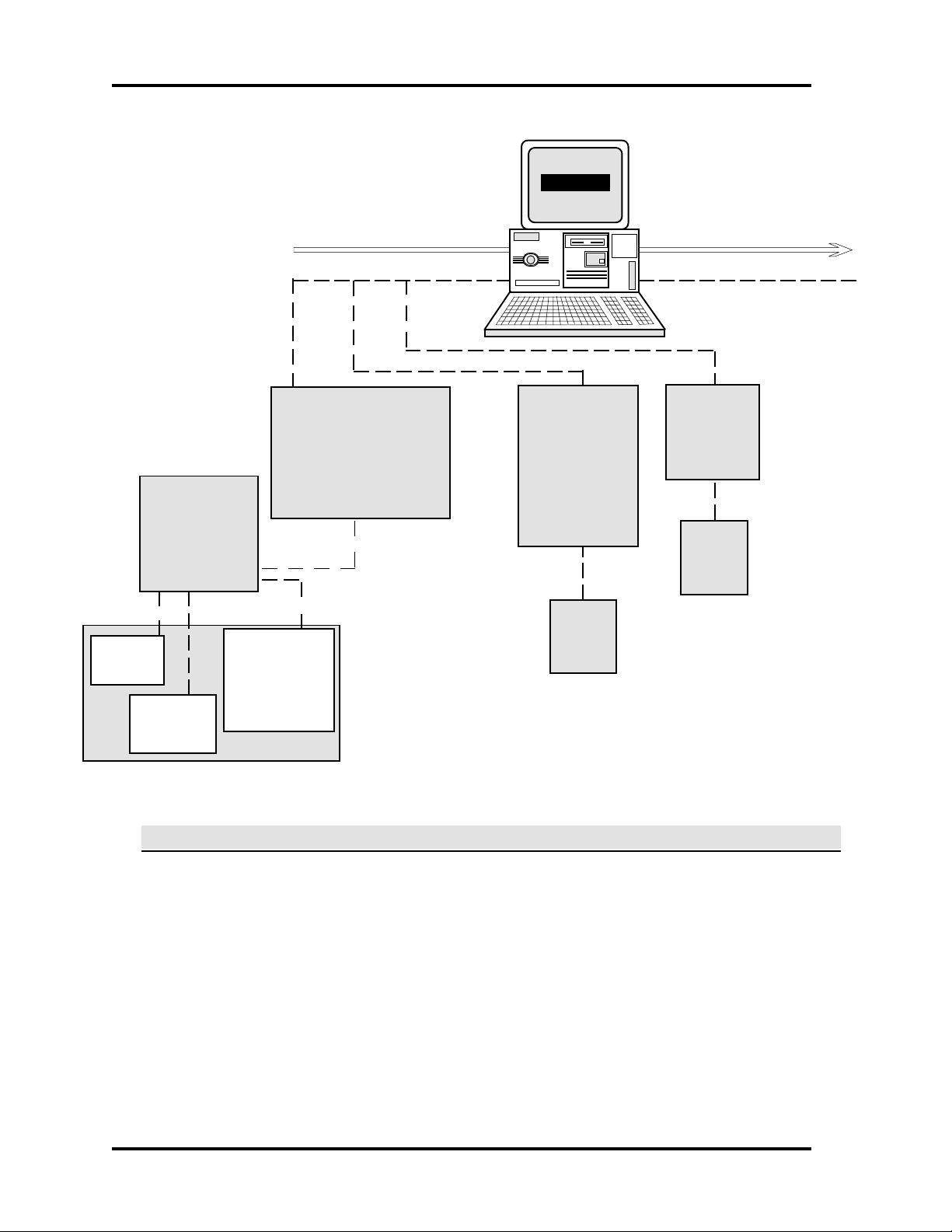
SAMPLE SYSTEM
An illustration of a basic SE 6000 system follows:
Page 15
1-8 SECTION 1: INTRODUCTION
SE 6000
Multiple Switch
Monitor—MSM
Contacts
1 2 3 4
REX
(Point)
Pollers
1234 5678
Access Control Unit—
ACU
(Up to 16 per poller)
Sensor Connections
1 2 3 4 5 6 7 8
Reader
Alarm
Monitoring
Device
(Up to 16 per poller)
Contact Relays
(1—16)
Contact
Switch
(Point)
Switcher
CCTV
Camera
Door Switch
(Point)
One Complete Door
CREATING THE DATABASE
Once the system is in place, first obtain the following from the system installer:
System Interconnect Diagram. This shows all wiring and connections in the system, and
provides information needed for entering pollers, devices, readers, and points.
Poller Initialization Parameters Information. The information shows how the pollers were
initialized, including poller type, physical port connection, and other poller-specific information.
Because all system activity is based on four-digit ID numbers, you need to decide before data entry
how these numbers are to be assigned to the system hardware elements. Although the numbering
system is entirely the choice of the SE 6000 owner, we recommend one of the two following
methods:
B
ASIC
SE 6000 S
YSTEM
Page 16

SECTION 1: INTRODUCTION 1-9
1. Following the System Interconnect Diagram, number each element in turn with a four-digit
number, including numbers for devices, pollers, and readers.
2. Use the following ID groupings for average-sized system:
0001-0010 — Computers 2000-2999 — Door switches
0011-0099 — Pollers 3000-3999 — REX contacts
0100-0999 — Devices 4000-5999 — Input points
1000-1999 — Sensors 6000-7999 — Outputs
Data Entry Sequence
Note that although the zoom feature (described later in this section) permits faster data entry, WSE
recommends the following sequence for most efficient data entry when you are creating your
database (data entry is detailed in Section 4: Master File Entry):
1. Time Codes 9. Access Groups 17. Tasks
2. Tenants 10. User-Defined Fields 18. Events
3. Zones / Areas 11. Keyholders 19. Enable Terminals for Global Alert
4. Pollers 12. Access Privileges 20. Program Security Levels
5. Devices 13. Holidays 21. Add Users
6. Points 14. Alarm Instructions 22. Passwords
7. Readers 15. Maps 23. System Owner Name
8. Access Codes 16. Transactions 24. Terminals for Alarm Auto-Switch
NOTE
Consult the system installer if you have questions concerning numbering. In any case, keep track
of your numbering method and advise each operator of the method selected
BASIC SYSTEM USAGE
This subsection gives introductory information for using the SE 6000 system, and includes related
miscellaneous information.
Logging On
Power on the system terminal. The screen displays a brief welcome message followed by the login
and password prompts. Enter the login ID and password in lowercase letters. If uppercase letters
are entered by mistake, log off using uppercase letters then log on again with lowercase letters.
If the login and password are not valid or if one or both were not entered correctly, the computer
responds with login incorrect then displays login again. Reenter the login ID and password making
sure that each letter is correctly typed. If the login incorrect message continues, consult the system
administrator. When logged in correctly, the system displays the SE 6000 title page, sets the
terminal environment, then displays the main menu. Call WSE Customer Service if you have a
login problem.
Page 17
1-10 SECTION 1: INTRODUCTION
System Screens
There are two basic screen types: Menu and Application:
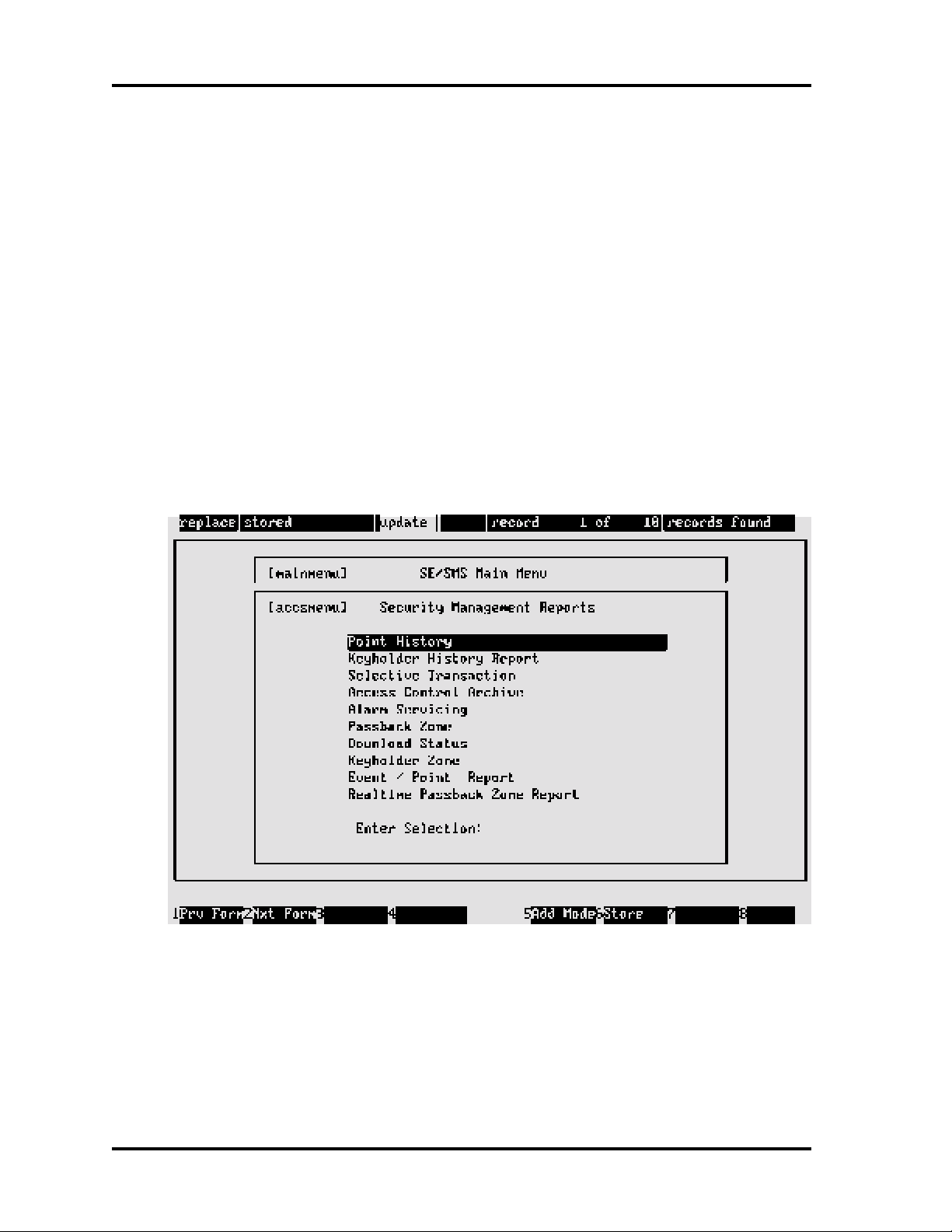
Menu Screens
Menu screens list application selections by group according to function (exception Monitor
Security Activity — see Section 2). All menu screen IDs end in menu (example: [fmntmenu] —
Master File Entry).
The menu screens have three elements: the list of choices, the highlight bar, and the Enter
Selection field. The highlight bar, controlled by the arrow keys, is used to make a selection to be
placed into the Enter Selection field. Screen access descriptions are given in Moving Between
Screens and Fields in this section.
A sample menu screen follows:
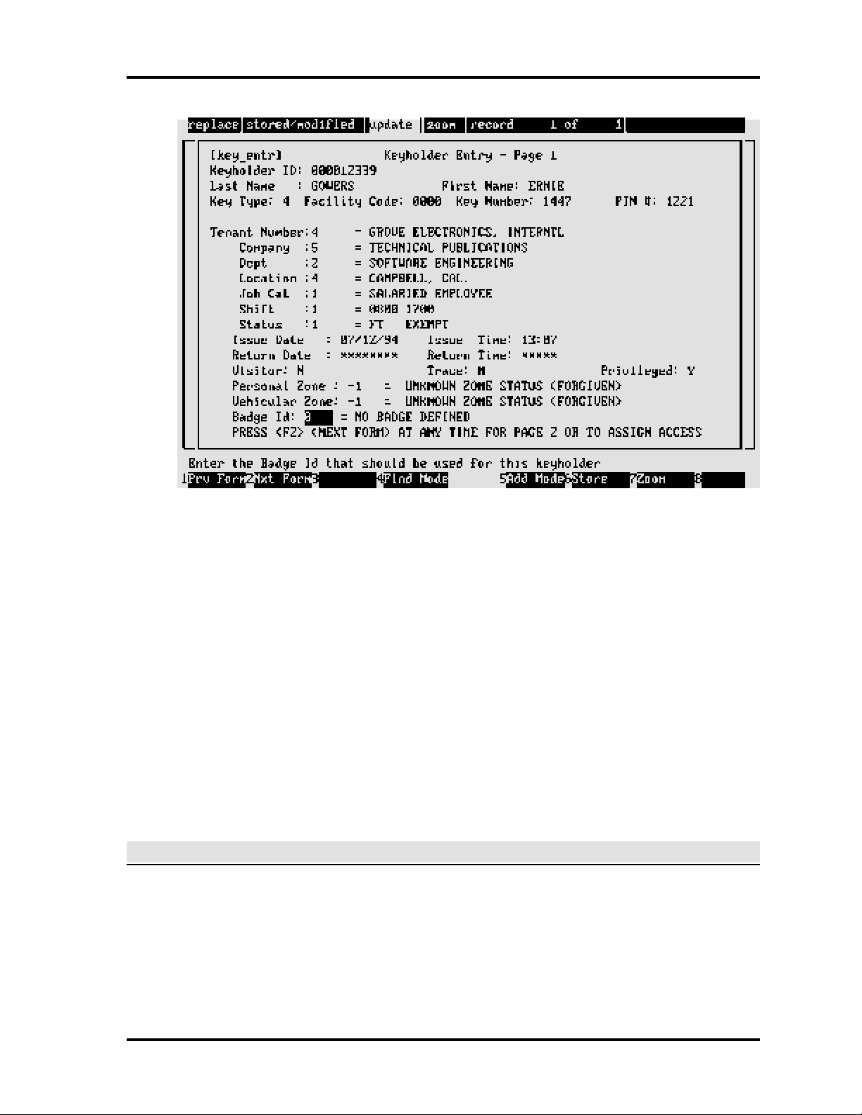
Application Screens
Application screens use status windows and various fields for entering new data or displaying
existing data. The screen title is in brackets and on the same line and to the left of the screen title.
Most screen title IDs indicate screen function, e.g., entr (enter data), rprt (report). A sample
screen follows:
Page 18
SECTION 1: INTRODUCTION 1-11
Indicates replace or insert mode. With replace, entries overwrite existing data. With insert,
entries push existing data to the right. Toggle between the modes by pressing insert.
Indicates if the information displaying is stored.
Indicates the current screen mode (see Finding, Adding, and Storing Data in this section).
In some systems, this window is in reverse video.
Indicates if the zoom feature exists for a field (see Zoom Feature in this section).
Displays the number of records found as a result of a find request (see Finding, Adding, and
Storing Data in this section).
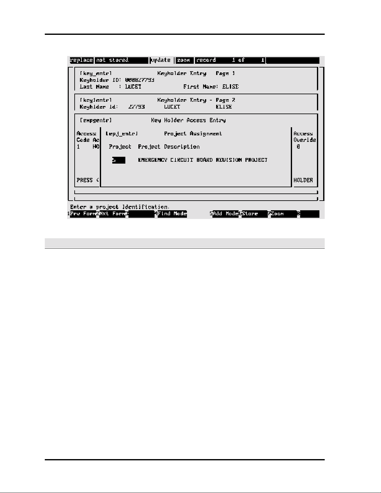
SCREEN EXAMPLES
SE 6000 screen displays show the path used to access the screen. For example, the final screen
used when setting up keyholders, [epj_entr], is accessed via three preceding keyholder setup
screens: [key_entr], [key1entr], [empgentr]. This useful feature considerably assists the new SE
6000 user when becoming familiar with the system. A sample [epj_entr] screen follows:
Page 19
1-12 SECTION 1: INTRODUCTION
USING SCREENS AND FIELDS
Selecting Screens
There are three screen selection methods:
1. Use the arrow keys to select the menu choice. Press Enter to place it in the Enter Selection
field, and press Enter again to display the selection.
2. Use the arrow keys to select the menu choice, and press F2 to display the selection.
3. Press Enter anywhere in the list of choices to move the highlight bar to the Enter Selection
field. Press Ctrl + y to clear the field and type the title of the screen required and then press
Enter.
Moving Between Data Fields
Move between the application screen data fields as follows:
• To move forward through the fields, press Enter.
• To move backward through the fields, press Ctrl + u.
• To move between characters within a single field, use the left and right arrow keys.
Page 20

SECTION 1: INTRODUCTION 1-13
Moving to Prior Screens
Press F1 to return to the previous screen displayed. If required, continue to press F1 to return
to the system main menu.
FINDING, ADDING, AND STORING DATA
Finding Data
Use the find mode to locate and select data. A specific record (a single keyholder ID, for example)
or a group of records (all keyholders in a particular job category, for example) can be found.
For example, assume we need to find all keyholders assigned to tenant 2 who began work after
May 1, 1995. First, select the keyholder entry screen, [key_entr]:
NOTE
The keyholders are the object of the search, which is why we begin at the keyholder entry screen.
Tenant 2 and issue date are the search criteria.
1. Press F4 to clear fields and to enter the find mode. The third status field at the top of the
screen displays find.
2. Press Enter to advance the highlight bar until you reach the first search item, Tenant, and
type 2.
3. Press Enter to advance the highlight bar until you reach the second search item, Issue Date,
and type 05/01/96. (Note: Enter the date according to the format for your system, that is, either
MM/DD/YY or DD/MM/YY.)
4. Press F3 to begin the search process; the sixth status field displays finding. The length of
the search process will depend upon the size of the data base.
5. When the search completes, the system displays the first record found and shows the
number of records found in the fifth status window (Record 1 of n). (If the system doesn't
find any records matching the search criteria, the message No Records Found displays.)
Use the down arrow key to display other records found in the search process. Use the up
arrow key to go back to previous records.
Searching With Partial Information
Records can be found using partial information. For example, to find all keyholders whose last
name begins with T, enter T in the Last Name field. The system also searches for several criteria.
For example, to find all keyholders who work for tenants 1 and 5, enter 1,5 in the tenant field. In
addition, you can enter less than (<) and greater than (>) symbols to narrow a search.
Page 21

1-14 SECTION 1: INTRODUCTION
The computer automatically changes to the update mode when a search completes, and the
records selected can be updated if required. To start another search, press F4 to clear the screen
and begin again.
Adding / Changing Data
The add mode is used to input new records. Once a record is found using the search mode, update
is automatically selected which allows the user to change the existing data.
If not already in the add mode, press F5 to clear fields and to begin adding. Press Enter to move
the highlight bar to the next field and type the data. (If a typing mistake is made, press Ctrl + y to
clear a field, Ctrl + f to delete characters in a field, Ctrl + u to move back through the fields.)
Many fields have default values, which are used if a field entry is not made. Default values are
used to simplify the entry process by automatically setting certain fields to commonly used values.
For example, many yes or no type fields, (Y / N), have Y as the default.
Storing Data
Store all additions and changes when completed — Press F6. If F1 is used to return to the previous
screen without first storing the new / changed information, all the new data is lost.
DELETING RECORDS
From time to time, it may be necessary to delete records from the database. The delete record
function is easy to perform, although some cautions are involved. To remove a record from the
database, first display the record using the find mode, then press Esc, followed by d (lowercase),
then r (lowercase). If the operation can be performed, the computer displays deleted.
It may not be possible to delete records in some cases. For example, the system would not allow
a reader to be deleted without first deleting its associated access codes. Display the access code
records and delete the reader data appearing on them, then delete the reader record itself again.
CAUTION
Be careful when deleting certain records. For example, it is unwise to be hasty when deleting
keyholder records. Consider Employee A who occasionally entered a certain room where
valuable material is stored. The employee then abruptly left the company, and the keyholder
record is deleted. A theft is then discovered from the room, and from shipping and receiving
records it is determined that the theft occurred within a particular time frame. But with the
keyholder information now erased for Employee A, there is no way to link the transaction history
to a particular keyholder.
Page 22

SECTION 1: INTRODUCTION 1-15
ZOOM FEATURE
The zoom feature provides a fast method for accessing linked or dependent application screens
and for copying data from these screens to other application screens. When the feature is
available, zoom displays in the status bar.
For example, you are entering keyholder data (keyholder entry screen) but don’t know the tenant
code for the keyholder. When in the tenant field, press F7 to zoom to the tenant entry screen. Once
there, use the find mode to see the tenant codes defined and to select the one you need or enter
a new one. Then press F1, and the system automatically returns you to the keyholder entry screen
and enters the keyholder's tenant code in the tenant field.
Cancel Zoom
If you don't need data from the zoom screen, press Esc, then Ctrl + z to return to the previous
screen, or simply return using F1 and key over the returned data.
MISCELLANEOUS INFORMATION
• If you need help in any field in the system, check the instructions on the information line at
the bottom of the screen.
• If the computer beeps and displays a message, or if you see the symbol '---' in the information
area at the bottom of the screen, press Enter to let the computer know you've read the
message. The computer will not allow further action, and will beep each time you press a
key until you press Enter to acknowledge.
• Occasionally, a screen will not display properly. This can occur when accessing the system
from a remote dial-in terminal via a modem or when the system administrator sends a
message. If this happens, try using Ctrl + r to redraw the screen. To completely clear the
problem, log off the system and log on again.
• To save time when moving around the SE 6000 system, it pays to learn the screen titles of
the most commonly used application screens (see the screen location trees and the table
at the end of this section). For fast screen access, type a screen title in the Enter Selection
field (press Enter in any menu screen), then press Enter and the system immediately displays
the screen. Note that you should delete any characters remaining in the Enter Selection field
before you select Enter.
LOGGING OFF
When the SE 6000 session is completed, press F1 until you reach the main menu screen. From
here, press F1 again; the computer asks for log off confirmation. Enter yes (full word) and press
Enter to leave the system. (You can also type exit in any Enter Selection field to leave the system.)
After log off, the computer displays the login prompt again.
Page 23

1-16 SECTION 1: INTRODUCTION
IMPORTANT
Log off the SE 6000 system formally before you leave the terminal. If you do not log off, any action
taken by the next person at the terminal will appear under your name.
SHUTTING DOWN
Always use the following procedures, in the order given, when powering off the SE 6000:
1. Go to the main system terminal (system console). This terminal has overall computer control
and displays all system messages.
2. Log off the system using the procedures given in the previous subsection.
3. Log in using the SHUTDOWN login. Your system administrator will provide you with the
password. If other users are still logged on, you may have to press Enter to continue the shut
down process which will forcibly log off other users.
Step 3 automatically shuts down the SE 6000 system in an orderly way. The last message
displayed when the internal shutdown procedures have completed is Safe to Power Off or Press
any Key to Reboot. It is now safe to power off the computer. To restart the computer, press any
key and follow the instructions in the following subsection.
RESTARTING
Use one of the following methods, Automatic or Manual, when powering on the SE 6000 (the
shutdown / restart process is also known as rebooting the computer).
Automatic Restart
The SE 6000 has an automatic restart capability that reboots the system in the event of a power
interruption. If unattended, the Boot prompt displays for 30 seconds, then the auto-boot function
reloads the operating system and restarts the application including the pollers.
Manual Restart
1. Turn the power on; the computer displays Boot. Press Enter to continue.
2. After various messages, the computer displays Type Control-d to Proceed with Normal
Startup (or give root password for system maintenance). Press and hold the Ctrl key, and
press the d key (lowercase).
Page 24

SECTION 1: INTRODUCTION 1-17
3. The computer displays Enter new time ([yymmdd]hhmm). Change the date and time values
as required (do not enter the parentheses or brackets); press Enter when completed. To
keep the displayed date and time, press Enter.
4. The computer continues its startup procedures, and the login prompt displays after a brief
pause. If any other message displays apart from those noted here, just press Enter.
SYSTEM SCREEN TREES
The SE 6000 screens are arranged in tree structures, with hierarchies established from the
primary screen to the lowest level screens in each tree. Each screen has a unique title which
displays in the upper-left.
Appendix A: System Screen Trees
Tree structures for the first seven standard-product selections on the system main menu are given
in Appendix A:
• Monitor Security Activity
• Security Management Reports
• Master File Entry
• Master File Reports
• Key Inventory / Parking Stickers
• System Administration
Appendix B: System Screen Hierarchies
Appendix B lists all screens within their respective tree structures, along with a brief explanation
for each. Left column indentions show the relative position of each screen within the individual tree
structures. Indented screens can be accessed only from the previous level in the screen hierarchy.
OPTIONAL FEATURES
A variety of optional software packages are available with the SE 6000:
IQ. A report writer package that allows the user to select, sort, display and / or print database
information in a format specified by the user. It can be used for quick ad hoc enquiries or formal
reports. Once defined, report formats may be saved and rerun on demand.
CCTV Camera Switcher Control. Controls the actions of closed-circuit television system
switchers, allowing the system to switch video output from a particular camera to a specified
monitor. When used in conjunction with the system flexible event handling feature, this provides
an important method for monitoring system events.
Page 25

1-18 SECTION 1: INTRODUCTION
Controller Systems. Controller systems are computers running the SE 6000 local (LC) or remote
location controller (RLC) software. The LC system is a computer attached via dedicated lines to
the host. The RLC system is a computer attached via dial-up telephone lines to the host.
Elevator Control. Permits floor-by-floor control of elevator call buttons. When a keyholder
presents a key to a reader in the elevator, certain buttons, wired via computer-controlled output
contracts, can be enabled or disabled for use. The keyholder is able to select only those which
have been enabled for his / her specific access privileges.
Guard Tour. Schedules and monitors security personnel guard tour activities. Specifies certain
reader output points as guard tour points, and assigns the minimum and maximum times which
can pass between stops on the tour. The feature reports if tours have started too early or too late,
or if too little or too much time has passed between stations.
Parking Control. Controls and monitors a parking facility including employee and revenue
generating parking spaces. Includes keyholder and daily cash customer functions, tenant billing,
and overage features. Supported hardware includes point-of-sale terminals, automated ticket
dispensers, and gate control mechanisms. Produces detailed reports for keyholders, cash
customers, parking lot attendant activity, and keeps track of the number of cars in the lot on a
tenant-by-tenant basis.
Remote Dial-Up Interface (RDI). Permits communication with remotely-located 8xx-series
devices via dial-up telephone lines. The feature retains transaction information, and determines
when conditions at a remote site warrant a call to the host (alarm event occurring, log buffer
reaching a user-defined threshold, etc.). Frequency and call duration are determined by the user.
The host contacts remote sites in turn to access information and to transfer event logs.
Time and Attendance. Captures hours worked by each employee for transfer to a payroll or
accounting system. The feature can be programmed to:
• Generate specialized reports of time and attendance activity.
• Monitor the number of meals taken by a keyholder.
• Recognize early and late entrances and exits.
• All records can be edited and modified prior to transfer to another system.
Visitor Control. Tracks visitors, prints visitor badges (black and white or color), and creates
comprehensive reports of visitor activity. The feature also provides a record of who was visited
and the date. It provides the company name of the visitor if applicable.
WSE ID-4000 Interface. Integrates one or more Polaroid ID-4000 photobadging systems with the
SE 6000. Keyholder information and photo IDs created on the Polaroid system are transferred
via a LAN or serial connection to the SE 6000. Badges can be printed on film or on PVC. Keyholder
maintenance may be initiated on either system; all data is stored in a single database resident on
the SE 6000.
Page 26
SECTION 2: MONITOR SECURITY ACTIVITY 2-1
SECTION 2
MONITOR SECURITY
ACTIVITY
INTRODUCTION
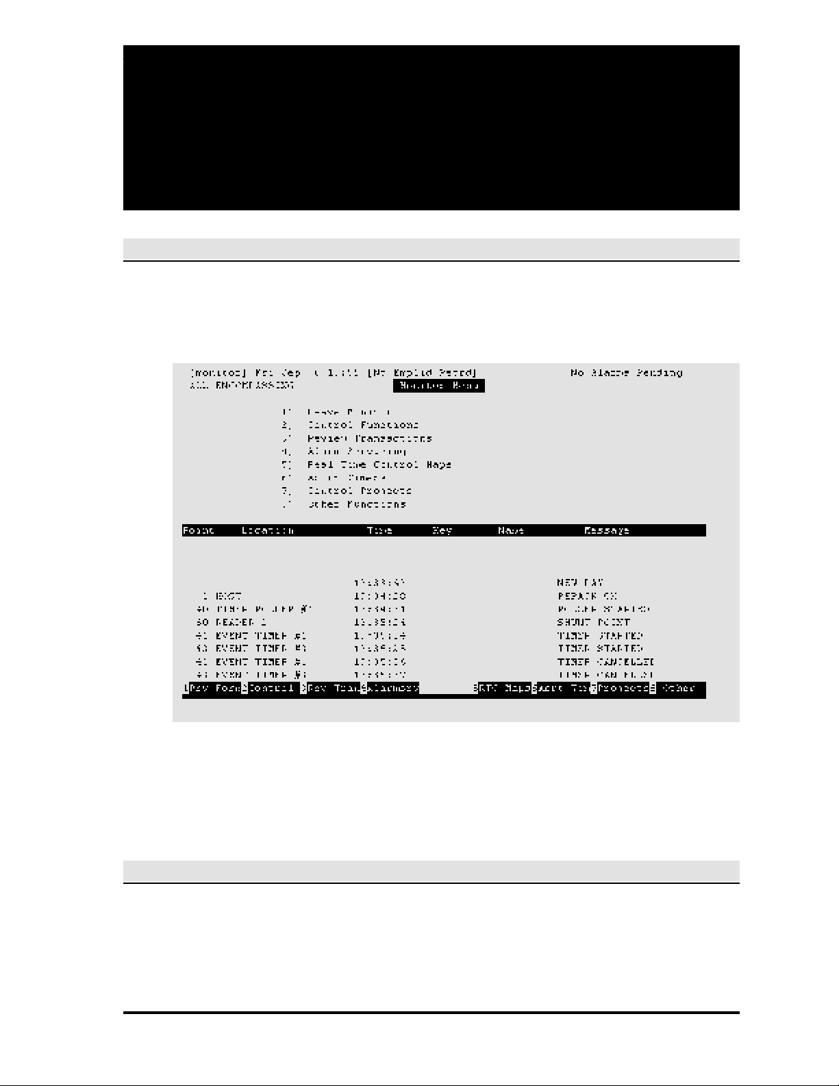
System monitoring and control is performed via the monitor menu, the first selection in the system
main menu. The monitor menu screen is shown below.
Notice this is a split screen, with the lower half constantly updated as transactions (any system
event) occur. Most monitor screens are divided this way, and for user convenience the screen
examples from this point on are shown without the transaction listings. Also, other screens not
accessed from the monitor menu in this section are reduced to show the required data fields only.
SECTION ORGANIZATION
The procedures in this section are in the order shown in the monitor menu (above). The associated
subscreens also follow in order (the section table of contents reflects the hierarchies).
Page 27
2-2 SECTION 2: MONITOR SECURITY ACTIVITY
FUNCTION KEYS
Beneath the transactions display are the applicable function keys for each screen, with the key
actions shown next to the key numbers. For most function key actions, the system displays
messages confirming that the action has been completed, e.g., POLLER STOPPED.
In general, F1 is used to exit from the current screen, and F7 and F8 are used respectively to
display the previous screen and the next screen within the set of screens that apply to the particular
data item being controlled or when there are more items then will fit into a single screen.
DATA ITEM SELECTION
Use the up and down arrow keys to select the data item to be controlled, then press the applicable
function key for the system action to be taken.
CONTROL FUNCTIONS MENU
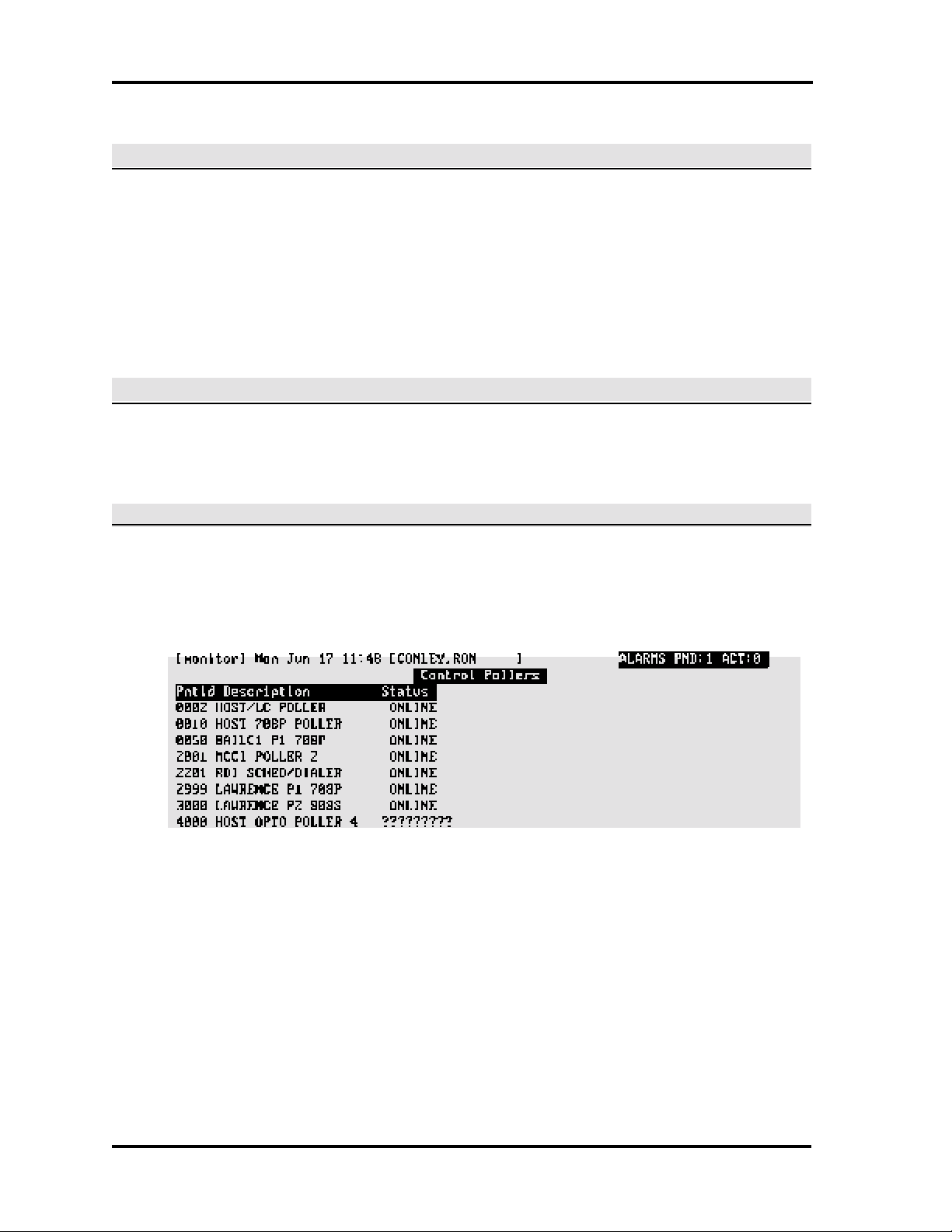
Pollers
The Control Pollers screen displays point ID, description, status.
Control Pollers Function Keys
F2 HALT. Stop a poller when work is to be performed on devices attached to the poller or to reload
a poller parameter following a change.
F3 RESTART. Restart the poller when work is completed (system displays messages announcing
each device attached to the poller as it comes back online). If there are devices with system or key
checksum errors, perform a reset to the device.
F4 DEV COMM. This function monitors communication between the pollers and the device pollers.
In normal operation, the devices are asked for information by the pollers many times a second,
and with a properly operating system the controller screen updates rapidly.
Page 28
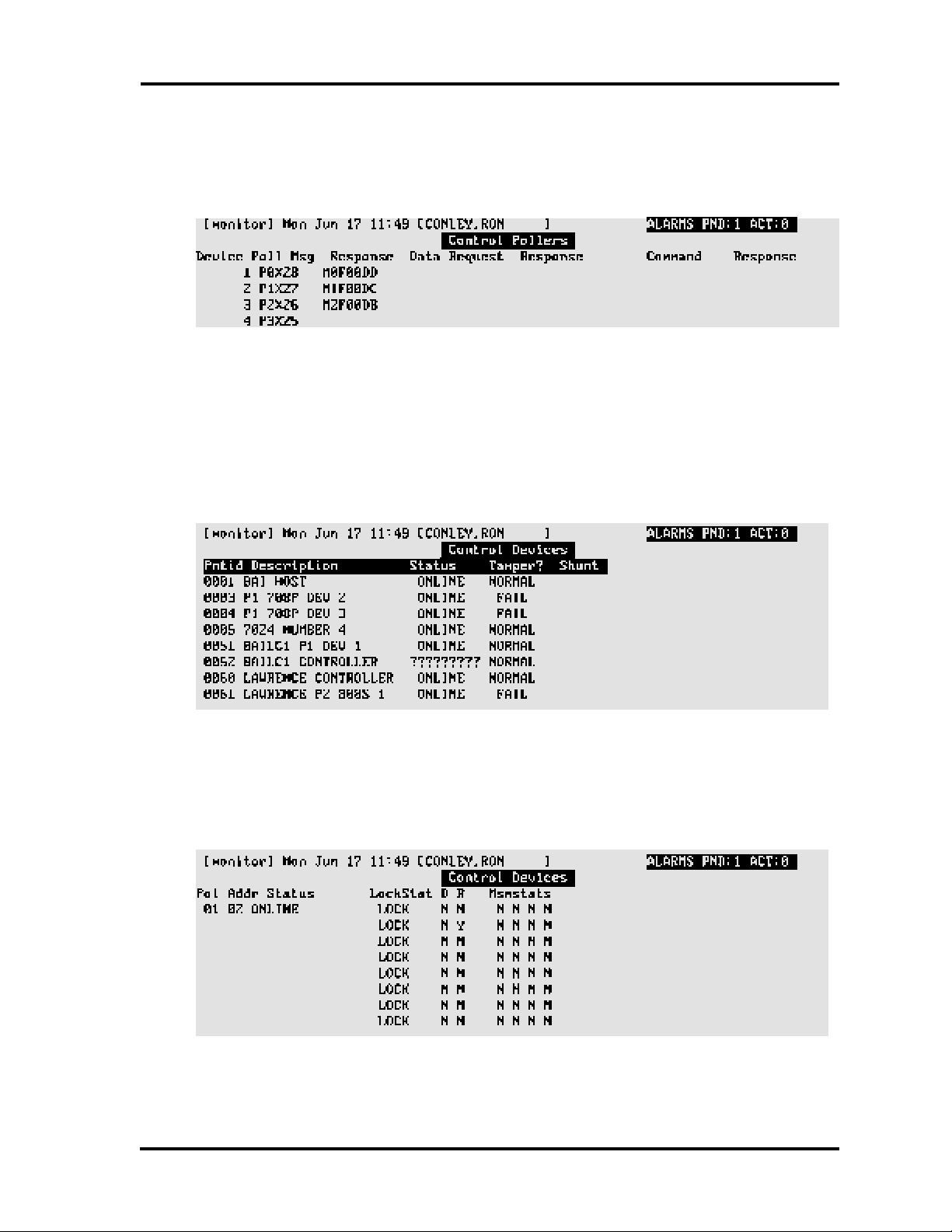
SECTION 2: MONITOR SECURITY ACTIVITY 2-3
When F4 is pressed, a second screen displays showing the connections between the host and
the devices of the particular poller selected:
Poller-device communication should be one of the first items checked whenever there is an
apparent problem with the system.
Devices
The Control Devices screen displays point ID, description, status, tamper, shunt. Applies to
NexSentry, 422, and 8xx-series ACUs.
Control Devices Function Keys
F2 DEV STAT. Device Status—When F2 is pressed, a second screen displays showing the status
of the particular device selected:
F3 DEV RSET. Device Reset—Used when setting up new ACUs or reestablishing repaired ACUs,
or when the integrity of the data currently resident in the ACU is suspected. Downloads all host
device data to the ACU and silences a latched alarm.
Page 29

2-4 SECTION 2: MONITOR SECURITY ACTIVITY
F4 KEY RSET. Key Reset—Used when setting up new ACUs or reestablishing repaired ACUs,
or when the integrity of the data currently resident in the ACU is suspected. Downloads all host
key data to the ACU.
F5 SHUNT. Shunt a device.
F6 UNSHUNT. Unshunt a device previously shunted.
Locks
The Control Locks screen displays point ID, description, lock status, shunt, sensor, coax, door
status.
Control Locks Function Keys
F2 LOCK. Lock selected door. If no door is selected, F2 locks all doors in the zone.
F3 UNLOCK. Unlock selected door. If no is door selected, F3 unlocks all doors in the zone.
F4 TIME OPEN. Unlock selected door for the amount of time programmed at the ACU or on the
reader entry screen. If no door is selected in a zone, F4 unlocks all doors in the zone for the amount
of time programmed.
F5 SHUNT. Shunt a door.
Page 30
SECTION 2: MONITOR SECURITY ACTIVITY 2-5
F6 UNSHUNT. Unshunt a door previously shunted.
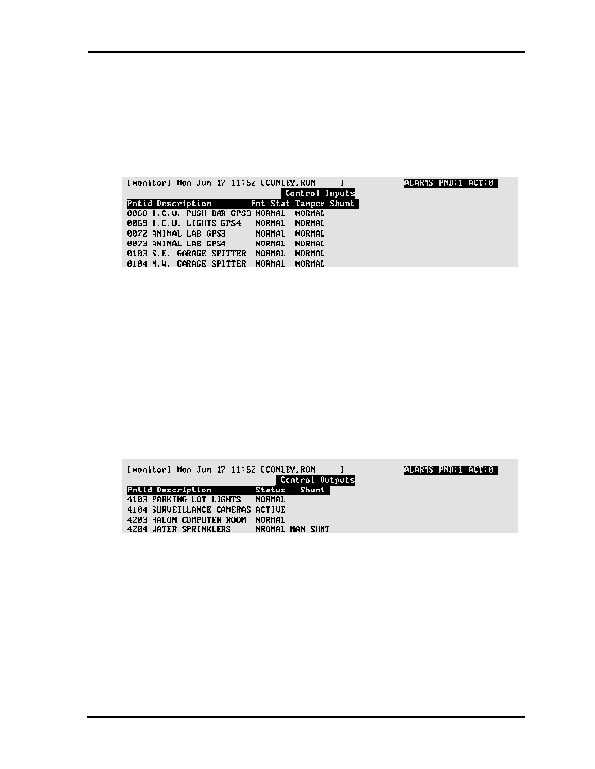
Input Points
The Control Inputs screen displays point ID, description, point status, tamper, shunt.
Control Inputs Function Keys
F5 SHUNT. Shunt a selected input point. If no input point is selected, F5 shunts all input points
in the zone.
F6 UNSHUNT. Unshunt a selected input point previously shunted. If no input point is selected,
F6 unshunts all input points in the zone.
Output Points
The Control Outputs screen displays point ID, description, status, shunt.
Control Outputs Function Keys
F2 ACTIVATE. Activate a selected output point. If no output point is selected, F2 shunts all output
points in the zone.
F3 NORMAL. Deactivate a selected output point. If no output point is selected, F3 deactivates all
output points in the zone.
F5 SHUNT. Shunt a selected output point. If no output point is selected, F5 shunts all output points
in the zone.
Page 31

2-6 SECTION 2: MONITOR SECURITY ACTIVITY
F6 UNSHUNT. Unshunt a selected output point previously shunted. If no output point is selected,
F6 unshunts all output points in the zone.
Doors
The Control Doors screen displays point ID, description, status, and shunt of the door switches.
Control Doors Function Keys
F5 SHUNT. Shunt a selected door. If no door is selected, F5 shunts all doors in the zone.
F6 UNSHUNT. Unshunt a selected door previously shunted. If no door is selected, F6 unshunts
all doors in the zone.
Select Zone
The Select Zone screen displays zone, description, count, PBarea, PBtype, PBlevel (see F3
RSET CNT below).
Use the arrow key to make the desired selection and press F2. Control activity remains exclusively
for this zone until you return to the monitor menu.
The keyholder count fields apply if passback control is in effect for the zone selected
Select Zone Function Keys
F2 SEL ZONE. Select zone.
F3 RSET CNT. If passback control is in effect for a zone, the following display:
Page 32

SECTION 2: MONITOR SECURITY ACTIVITY 2-7
Count — Number of keyholders currently in the zone.
PBarea — Passback zone type—personal, vehicle, none.
PBtype — Passback type —hard, soft, none.
PBlevel — Passback control—global (host), local (ACU), none.
Note that zone count is automatically reset whenever a zone is selected.
Multi-user systems employ record locking techniques for keyholder file maintenance, and locked
records are not updated by the passback routine that maintains keyholder location. If this occurs,
the keyholder count is correct, but the passback zone report (which reads the keyholder file) does
not include the locked records.
F3 corrects the zone count where privileged keyholders (not subject to passback control) have
reentered a controlled zone without having exited in the normal manner or when the previous
defined condition exists.
REVIEW TRANSACTIONS (FULL SCREEN)
This feature displays all transactions in the review transaction memory. Typically, the last 3,000
transactions which occurred are available. To view the screen without interruption, new
transactions do not appear when using this function. If no keyboard action is taken with this feature
for a five-minute period, the system returns to the monitor menu. A sample full screen follows:
Page 33

2-8 SECTION 2: MONITOR SECURITY ACTIVITY
Review Transactions Function Keys
F2 BACKWARD. Page backward through the transactions.
F3 FORWARD. Page forward through the transactions.
F4 OLDEST. Go to first transaction.
F5 LATEST. Go to last transaction.
ALARM SERVICING
The system emits beeps when an alarm occurs, and displays the number of pending and active
alarm data in the upper-right corner of the monitor menu screen: Pending—alarm condition no
longer occurring but not yet formally resolved. Active—alarm condition still occurring. Begin
resolving alarms using the alarm servicing screen:
Alarm Servicing Function Keys
F2 VIEW MAP. Press F2 to display a map showing alarm location. Location indicated by the point
ID in a red rectangle (other map symbols do not display when an alarm is triggered).
F3 INSTRUCT. Instructions—Press F3 to display a list of actions to take in response to the alarm.
F4 RESPONSE. Press F4 to display the alarm response entry screen. First enter Y or N in the
situation resolved field (Y cannot be entered if the alarm is still occurring—take action to halt the
alarm condition), then enter the actions taken. A printable record of these actions is written to disk
(see Section 3: Alarm Servicing Report).
F5 FAST ACK. Fast Acknowledge—Press F5 and the alarm is considered resolved (use with
caution because this does not allow entry of operator response to an alarm).
F6 SIL ALL. Silence All—Press F6 to silence beeping at all terminals.
REAL TIME CONTROL MAPS
System activity can be monitored using the system map function (created using the DRAWMAPS
function—see Section 4: Maps). The maps display triggered alarms (icon displays in red; goes
to yellow when pending), door status (message displays), device shunt status (message displays),
door unlocks (icon goes from black to white).
Page 34

SECTION 2: MONITOR SECURITY ACTIVITY 2-9
CONTROL PROJECTS
The Control Projects screen (not controllable on LC systems—host only) displays project, status,
description, start, end. The control projects screen permits operator override of doors assigned
to projects which directly affects keyholder access.
Control Projects Function Keys
F2 ACTIVATE. Activates a project.
F3 DE-ACTIV. Deactivates a project.
F4 NORMAL. Normalizes a project based on start/stop dates and time.
ABORT TIMERS
The Abort Timers function (F6) allows you to stop interactive timers that have started.
OTHER FUNCTIONS
Printer Control
Control Printers Function Keys
F3 RELOAD. Reloads printer data from the host which resets the printer logic and font size.
Page 35

2-10 SECTION 2: MONITOR SECURITY ACTIVITY
F5 PRNT ON. Switch printer #1 on or off depending on current state (used to control log printer
only).
F6 PRNT ON. Switch printer #2 on or off depending on current state.
Forgive Passback
A passback violation occurs when a keyholder uses their key to reenter a door without first using
their key to exit the same door. For example, a keyholder (number 1) uses their key and unlocks
the door. The system flags keyholder number 1 as "in." Keyholder number 1 passes their key to
keyholder number 2. When keyholder number 2 attempts to use the key, the systems gives
keyholder number 1 a passback violation. This was originally developed for parking lot control.
The system handles vehicle and personal passback separately.
To allow the keyholder to enter the area, use the forgive passback function.
1. Enter key number (or ALL for all keyholders); press Enter.
2. Press F1 to confirm the passback forgive.
Manual Access Granted
Used when a command key is not available (mislaid, stolen, etc.), this function allows the operator
to grant manual access following entry of the key number (system records entry). Enter the key
number and reader ID. Enter the keyholder ID if the key number is unknown. Manual access is
available for all keyholders at any reader regardless of access assignments.
Force Table Download
This function first writes database information to a text file, then transfers the information to host
memory and LC memory (if applicable). The function is used during system servicing, and when
requested by customer support. A sample screen follows:
Page 36

SECTION 2: MONITOR SECURITY ACTIVITY 2-11
When requested, enter the number of the table to be downloaded and press Enter. The system
requests confirmation — press F1. REPACK OK displays when transfer completes.
Remote Devices
This function is used to establish a telephone connection to a remote device to perform certain
actions, for example, unlock a door to a remote ATM for Service. Note that the remote device
remains connected until the operator selects the device and presses F3-Hang Up.
Control Remote Devices Function Keys
F2 CALL/HLD. Call device.
F3 HANGUP. Disengage connection.
Building Modes
Building modes — open, closed, limited — combined with the ACU report definitions provide an
extra level of security when the building is empty or a reduced number of staff are present. Door
switches and / or other monitor points active in the building open mode can be configured to
generate alarms if activated when the building is in limited or closed mode. Also, if open mode,
closed mode, or station readers have been defined, reader operation for those locations will
change when the building mode changes. For example, an open mode reader will not read keys
when the building is in limited or closed mode.
Control Building Modes Function Keys
F2 OPEN. Change current building mode to open.
Page 37

2-12 SECTION 2: MONITOR SECURITY ACTIVITY
F3 LIMITED. Change current building mode to limited.
F4 CLOSED. Change current building mode to closed (takes approximately one minute to
complete). If a device input point configured to prevent building closure is active, the building will
remain in the limited mode until the point is cleared.
Full Screen Monitoring
Displays system logs in a manner similar to the review transactions feature (see Review
Transactions—Full Screen in this section) except that new transactions display as they occur. Use
F8 to toggle between full and half screen displays.
MISCELLANEOUS INFORMATION
Disk Almost Full Warning
This feature warns operators when the disk drive has reached a specified percentage of its total
capacity:
When the warning appears, take immediate action to reduce the amount of data stored on the disk
(delete unwanted files, etc.).
This feature uses the DISKWARN keyword parameter located in the $DATAPATH/PARAMS.M
file:
Parameter Default Condition
DISKWARN keyword missing — Defaults to 90%
DISKWARN =0 — Feature disabled
DISKWARN =n — Feature enabled; n is the range 1—99
NOTE
1. Shut down and reboot after changing DISKWARN parameters.
2. The DISK ALMOST FULL message is generated only once.
3. Since the message is generated only once, we recommend that system message #242 be
changed to an alarm event by changing the alarm priority field to a value greater than 0. See
Section 6, Transactions [tranentr] for details.
Page 38

SECTION 2: MONITOR SECURITY ACTIVITY 2-13
Status Screen Function Timeout
Some system functions temporarily disable the realtime display until the sub-menu is exited. The
status screen function Timeout feature provides a user-defined method for controlling the length
of time that the realtime display is disabled. If the system does not detect any keyboard or mouse
activity for the number of seconds defined by the TIMEOUT parameter, the monitor program
returns to the previous menu and resumes realtime display.
This feature uses the parameter file $DATAPATH/MONITOR, with the control parameter
TIMEOUT having a numeric value in seconds:
Parameter Default Condition
Parameter missing — TIMEOUT defaults to 0—feature disabled
TIMEOUT=0 — Feature disabled
TIMEOUT=n — Feature enabled using the numeric value n (five digits maximum)
TIMEOUT=600 — Feature enabled using the numeric value 600—600 seconds, default
NOTE
1. The control parameter is read by the monitor program at log-on time and remains in effect
as long as the monitor program is active. A change to the Timeout value does not take effect
until the user logs off, and then logs back on to the system (reboot not required).
2. This feature is operational with the following screens:
A. The device communication function of the control pollers screen (see Pollers in this
section).
B. The device status function of the control devices screen (see Devices in this section).
Alarm Servicing — No Activity Timeout
This feature controls how long the alarm servicing screen displays when there is no keyboard or
mouse activity. On Timeout, the system exits the alarm servicing program and returns to the
realtime display of system events.
This feature uses the $DATAPATH/ALARMSRV parameter file, with the control parameter
TIMEOUT having a numeric value in seconds: Acceptable values are:
Parameter Default Condition
Parameter missing — TIMEOUT defaults to 0—feature disabled
TIMEOUT=0 — Feature disabled
TIMEOUT=n — Feature enabled using the numeric value n (five digits maximum)
TIMEOUT=600 — Feature enabled using the numeric value 600—600 seconds, default
Page 39

2-14 SECTION 2: MONITOR SECURITY ACTIVITY
NOTE
1. The control parameter is read by the alarm servicing program at log-on time and remains in
effect as long as the alarm program is active. A change to the Timeout value does not take
effect until the user logs off, and then logs back on to the system (reboots).
2. Timeout is deactivated when responding to an alarm in the alarm response screen.
Monitoring Security - Passwords
With enhanced monitor security function and the addition of password logic, any or all portions of
the monitor functions can be set up to require a valid ID and password combination before the
function can be initiated. In place of the factory-supplied status login, the user may create a similar
login ID, with or without password, and control access to monitor capabilities. While many
operators may use the generic login, individual users will have only monitor privileges consistent
with their own custom security profiles.
This feature uses the PASSWORD keyword parameter located in the $DATAPATH/MONITOR
file. The acceptable values are:
PASSWORD keyword missing — Feature disabled
PASSWORD=0 — Feature disabled (default)
PASSWORD=1 — Feature enabled
This feature also requires that the user has a custom security profile. See also note #1 regarding
system upgrades with users created on an earlier version of the software.
Implementing the Feature
For additional information see Chapter 6, Adding a User.
1. Log on using an assigned login name and password, or use a generic login name (and
optional password) as required by facility procedures.
2. With the password feature enabled, any action attempted from the monitor for which
permission has not been granted causes the system to prompt for a login name and
password.
3. If the login name and password entered are valid, the associated security profile initiates the
action requested (see note #4).
4. If the feature is disabled or an incorrect login / password is entered, the system displays
PERMISSION DENIED.
Page 40

SECTION 2: MONITOR SECURITY ACTIVITY 2-15
NOTE
1. If your system has been upgraded, and users created on a previous release have been
saved, their user profiles must be updated with the new monitor security privileges. To
do this, log on as addusers with the correct password, select system administration, and
then select add users. Update the security profile for each user as follows:
- Enter the user ID
- Select modify—F5
- Press the return key through all fields
- Store the updated profile—F8
Repeat for all applicable users. The new custom security information is appended
without changing the current privileges.
2. If the password keyword parameter is changed, users must log off then log back on
(reboot) before a change is recognized by the monitor program.
3. All functions that generate log messages are logged with the user ID entered to gain
access to the requested function.
4. Permissions associated with the entered login ID remain in effect until the operator
returns to the point where the login ID and password were required, or, if the status
screen function Timeout feature has been enabled, the screen itself will Timeout (see
Status Screen Function Timeout Feature in this section).
Modified Usage of Invalid Facility Code Log
This feature suppresses a keyholder's name from the monitoring screen and various reports when
an INVALID FACILITY CODE message is logged. In some cases, this resulted in a log message
erroneously associating a valid keyholder with an invalid facility. This function is automatic and
does not require operator action.
NOTE
This occurred with the 708 type device where different facility codes were used on different
buildings. It only applies to 1030/1040 cards with facility codes where a user has keys with multiple
codes.
Page 41

2-16 SECTION 2: MONITOR SECURITY ACTIVITY
1. This feature affects the following displays and reports:
- Monitor screen, both full- and half-screen displays
- Review transactions screen
- Point history report
- Keyholder history report
- Transaction history report - all sort options
- Archive history report - all sort options
2. Log records are not altered.
Page 42

SECTION 3
SECURITY REPORTS
INTRODUCTION
Security management reports provide a permanent record of transactions, and are also used to
examine specific events. The reports are accessed through the security management reports
menu screen, [accsmenu], via the main menu. In this section, the reports are documented
following the security management reports menu sequence (see section table of contents). A
sample [accsmenu] screen follows:
All screens in this section show the system default values, with most screen fields requiring a
numeric range entry. For example, the default range for keyholders is 1 — 999999999 (to reduce
waiting time while a report is generating, enter the smallest range of numbers for each category
which will still provide the information required). Other screen fields include choices for a specific
data item, date ranges, regular or extended information, and report sequencing. When all fields
have been entered, press Enter (Yes - default) to begin report generation:
Once compiled, a report output selection displays. Normally, 1 (system report printer) or D (display
at terminal) is chosen. Report totals are printed at the end of each report.
Page 43

3-2 SECTION 3: SECURITY MANAGEMENTS REPORTS
NOTE
1. Some reports are over-wide (132 characters instead of the standard 80 characters), and
have been formatted to use a smaller print size not available with some terminals (HP printers
can handle the smaller print). These reports can be displayed but will 'wrap'; that is, some
lines continue to the next display line . In such a case, use the display option to check report
details, then use one of the print options to create a hard copy of the report.
2. For color PCs with Reflections 4 software, or an HP700/44, the display automatically
changes to the 132-column mode for any reports with lines exceeding 80 characters.
POINT HISTORY REPORT
The point history report, [phstrprt], lists transaction activity at a specific point. The report lists the
key number and name (if any) associated with a transaction, date and time, and description.
To facilitate processing, only the last 20 transactions are used. If more than the last 20 transactions
are required, use the transaction history report. A sample [phstrprt] screen follows:
Point History — Sample Report
06/27/96 Packlett Industries PAGE 1
14:36 Point History
KeyhldID Keyholder Name Date Time Access Description
________ _______________ _____ ____ _________________
166603 HALSTON RICHARD 06/24/96 16:50:47 MANUAL LOCK
166603 HALSTON RICHARD 06/24/96 16:50:46 MANUAL OPEN
166755 GREENE LORRAINE 06/24/96 16:50:45 MANUAL LOCK
166755 GREENE LORRAINE 06/24/96 16:50:44 MANUAL OPEN
161221 ROBINS JAMES 06/24/96 16:50:43 MANUAL LOCK
161221 ROBINS JAMES 06/24/96 16:50:42 MANUAL OPEN
163878 COUSINS TERRY 06/24/96 15:09:23 MANUAL LOCK
163878 COUSINS TERRY 06/24/96 15:09:21 MANUAL OPEN
165446 AVERY JOE 06/21/96 14:19:22 UNABLE TO UNLOCK DOOR
165446 AVERY JOE 06/21/96 13:55:47 UNABLE TO LOCK DOOR
KEYHOLDER HISTORY REPORT
The keyholder history report, [chstrprt], lists activities for a specific keyholder. Also, the report can
be used for tracking actions taken by a system operator. The report contains point or sensor data
showing where activity occurred, date and time, and description. To facilitate processing, only the
last 20 transactions are used. If more than the last 20 transactions are required, use the
transaction history report. A sample [chstrprt] screen follows:
Page 44

SECTION 3: SECURITY MANAGEMENT REPORTS 3-3
Keyholder History — Sample Report
06/27/96 Packlett Industries PAGE 1
14:36 Point History
Point Point Description Date Time Access Type
_____ ____________________ ________ ________ __________________
Keyholder 2771 Dale, Deborah
0225 RDI-8082-SEN2 06/27/96 09:32:52 ACCESS GRANTED
0221 RDI-8082-SEN1 06/27/96 07:34:24 ACCESS GRANTED
0215 RDI-8081-SEN1-READER 06/27/96 07:34:22 ACCESS GRANTED
0220 T&A READER 3 N/A 06/26/96 15:40:42 MANUAL OPEN
0210 T&A READER 2 OUT 06/26/96 15:40:40 MANUAL OPEN
0200 T&A READER 1 IN 06/26/96 15:40:34 MANUAL OPEN
0120 ELEVATOR FREIGHT CAR 06/26/96 15:40:31 MANUAL LOCK
TRANSACTION HISTORY REPORT
The transaction history report, [excprprt], lists all transactions according to selected criteria. The
transaction report function is used to create a who, what, where, and when report of all
transactions. This function includes information about the ID and description of the point or sensor
where the transaction occurred, the zone number of the point or sensor, the date and time of the
transaction, the type of access (for an access transaction) and the ID and name of the keyholder
involved with the transaction, if any. Two report types are available: short and extended. The short
report accesses all standard information; the extended report does the same but includes userdefined field information. A sample [excprprt] screen follows:
Page 45

3-4 SECTION 3: SECURITY MANAGEMENTS REPORTS
Transaction History — Sample Report
11/15/96 SHARPSMITH LABS, INC. Page 1
10:34 Access Control Transaction Report
Point Point Description Zone Date Time Access Type Keyholder Keyholder Name Key No
_____ _______________________ ____ ____ ____ _______________________ _________ ________________ ______
1 HOST 801 10/28/96 11:12:00 FORGIVE PASSBACK 661094 Stanling, Bob 34421
1 HOST 0 10/28/96 11:23:00 REPACK OK
1 HOST 801 10/28/96 13:37:00 FORGIVE PASSBACK 662886 Jonesman, Linda 32211
1 HOST 001 10/28/96 14:12:00 FORGIVE PASSBACK 656633 Buchmann, G.T. 34588
1 HOST 0 10/28/96 14:17:00 REPACK OK
1 HOST 0 10/28/96 14:49:00 FORGIVE PASSBACK 641918 Saunder, Rick 34876
ACCESS CONTROL ARCHIVE REPORT
The access control archive report, [acrtrprt], is identical to the transaction history report (previous
report) except that it reads data from an archive tape rather than from the system database.
ALARM SERVICING REPORT
The alarm servicing report, [almarprt], details actions taken by operators in response to alarms.
A sample [almarprt] screen follows:
Page 46

SECTION 3: SECURITY MANAGEMENT REPORTS 3-5
Alarm Servicing — Sample Report
06/27/96 PacAtlantic Racing PAGE 1
15:01 Alarm Master List
Alarm No Alrmtime Alrmdate Point Zone Resp Time Resp Date Clear Time Clear Date Serviced By
________ ________ ________ _____ ____ _________ _________ __________ __________ ___________
Point Descrip = CHEMICALS GPS 3
2851 09:18:00 06/26/96 20 3 14:19:05 06/26/96 11:10:10 06/26/96 Maintenance
Operator Response: Alarm Instructions:
CALLED FIRE DEPT. PUT ON MASK
CLEARED BUILDING CALL FIRE DEPARTMENT IMMEDIATELY
OPENED VENTS EVACUATE ALL PEOPLE FROM BUILDING
LEFT BUILDING OPEN EMERGENCY VENTS
REENTERED WHEN ALL CLEAR LEAVE BUILDING
PASSBACK ZONE REPORT
The passback zone report, [whowhere], lists keyholders currently present in passback zones. The
summary selection provides totals by zone, while the detailed report lists specific keyholders. The
source for the information is the keyholder file. A sample [whowhere] screen follows:
Page 47

3-6 SECTION 3: SECURITY MANAGEMENTS REPORTS
Passback Zone — Sample Report
04/05/96 Easthaven Manufacturing Page 1
14:43 Passback Zone Report
Keyholder Key No Keyholder Name Tenant Pzone Vzone
_________ _____ __________________________ ______ _____ _____
1055699 83383 MAITLING, JACK 0 -1 -1
1061128 84128 LYONS, CINDY 0 -1 -1
1086201 83361 DENEUVE, DENISE 0 0 -1
1099004 86660 SMITH, PAULA 0 1 2
1100015 87083 MACKLING, JACKIE 0 -1 -1
1116345 88883 FLYNN, SEAN 0 -1 -1
DOWNLOAD STATUS REPORT
The download status report, [downrprt], is used to create an audit-trail of system information
change attempts, the devices affected, who attempted the changes, and when and if the changes
were successful. A sample screen follows:
Page 48

SECTION 3: SECURITY MANAGEMENT REPORTS 3-7
Download Status — Sample Report
06/27/96 Nevadia Industries PAGE 1
15:03 Download Status Report
Serial # Key Value File Descrip Typ Date Time Maint By Status Point Point Descrip
_________ _________ ____ _______ ___ ____ ____ ________ ______ _____ _____________
21729 76 2 Points Chg 06/27/96 08:34 Paul Received & Processed 0 HOST
21730 76 2 Points Chg 06/27/96 08:34 Paul Received & Processed 60 1ST CNTRLLER
21731 76 2 Points Chg 06/27/96 08:34 Paul Received & Processed 61 CNTRL P28081
21723 21463 8 Events Del 06/27/96 08:31 Paul Received & Processed 0 HOST
21724 21463 8 Events Del 06/27/96 08:31 Paul Received & Processed 52 BAIL C1 CNTRL
21725 21463 8 Events Del 06/27/96 08:31 Paul Received & Processed 60 1ST CNTRLLER
21726 21463 8 Events Del 06/27/96 08:31 Paul Received & Processed 61 CNTRL P28081
Possible system messages for this report are:
Unprocessed — Information changed in the database, but has not yet been sent to the
communications program module.
Before Transmit — Information has been sent to the communications program module, but
has not yet been sent to target device.
Transmitted — Data has been sent from the host to the target device, but acknowledgment has
not yet been received from the target device.
Received and Processed — Information successfully transmitted by the host and success-
fully received by the target device (download completed).
ERR Transmitting Data — Error on host side of transmission. Normally, this means that the
host communications program module was unable to complete the requested download.
ERR Receiving Data — Information successfully transmitted by the host, but the target device
was unable to receive.
Page 49

3-8 SECTION 3: SECURITY MANAGEMENTS REPORTS
KEYHOLDER ZONE REPORT
The report lists the most recent zone information for all keyholders that meet the search criteria;
however, information is not necessarily current. A sample [kyznrprt] screen follows:
Keyholder Zone — Sample Report
05/12/96 Vogler Vineyards Page 1
14:41 Keyholder Zone Report
Keyholder Keyholder Name Tenant Point Point Description Date Time Zone
_________ ___________________ ______ _____ _________________ _______ _______ ____
10556 MAITLING JAMES 0 3120 808SX RDR 2 04/02/96 16:48:12 0
10564 LYONS SHELLEY 0 3120 808SX RDR 2 04/02/96 16:48:12 0
10569 MCDUFF GORDON 0 3120 808SX RDR 2 04/02/96 16:48:12 0
10622 DENEUVE DENISE 0 3120 808SX RDR 2 04/02/96 16:48:12 0
10643 SMITH PAULA 0 3120 808SX RDR 2 04/02/96 16:48:12 0
10701 HERALD RICHARD 0 3120 808SX RDR 2 04/02/96 16:48:12 0
EVENT / POINT REPORT
The event / point report, [evptrprt], lists the number of events of a particular type that have occurred
at a point or within a range of points. The report is limited to the current contents of the archive
history file. A sample [evptrprt] screen follows:
Page 50

SECTION 3: SECURITY MANAGEMENT REPORTS 3-9
Event / Point — Sample Report
03/17/96 Security Electronics Page 1
09:15 Event/Point Report
Point Point Description Tran. Tran. Description Occurrences
______________________________________________________________ ___________
1 HOST 231 PROJECT DEACTIVATED 2
1 HOST 242 DISK ALMOST FULL 5
2 DATA BASE POLLER 24 POLLER STARTED 1
2 DATA BASE POLLER 25 POLLER STOPPED 1
4 808/422 POLLER 222 POLLER STOPPED 2
4 808/422 POLLER 224 POLLER STARTED 12
REALTIME PASSBACK ZONE REPORT
The realtime passback zone report, [rpasrprt], is essentially the same report as the passback zone
report (described earlier in this section), with one important difference. The realtime report is
created directly from shared memory instead of from the database. This feature substantially
reduces the amount of time necessary to find out where keyholders are currently located. This
can be very useful for monitoring hazardous areas, or when it is important to rapidly determine the
number or identity of the keyholders in a particular zone.
Page 51

3-10 SECTION 3: SECURITY MANAGEMENTS REPORTS
REALTIME PASSBACK DETAIL — SAMPLE REPORT
03/14/96 McPowell-Angus Aviation Page 1
15:18 Realtime Passback Detail Report
Keyholder Key No Keyholder Name Tenant Pzone Vzone
_________ ________ _________________________ ______ _____ _____
223141 188954 McDaniels, Jeff 0 -1 -1
237473 140226 Wellington, Lambert 0 -1 -1
233974 195226 Du Pont, Michael 0 -1 -1
239965 200026 Senter, Carol 0 -1 -1
248366 180463 Pons, Antonia 0 -1 7100
249037 143511 Segwick, G.J. 0 -1 -1
Page 52

SECTION 4: MASTER FILE ENTRY 4-1
SECTION 4
MASTER FILE ENTRY
INTRODUCTION
The master file entry procedures are used to create and maintain the database. All initial system
data is entered following the methods detailed in this section. The data item menu screens are
accessed via the master file entry menu [fmntmenu], displayed via the main menu. A sample
[fmntmenu] screen follows.
Some master file entry procedures are used more frequently than others. For example, keyholder
data is usually added, changed, and deleted daily. On the other hand, additions or changes to
system configuration information may occur only once every several months.
Screen Access
The procedures in this section are in the order as they appear on the [fmntmenu] screen (above).
Following each menu entry are the associated subscreens, again in order (the section table of
contents reflects the hierarchy). After the current screen has been saved (F6), most subscreens
display by pressing F2 but some display automatically.
Page 53

4-2 SECTION 4: MASTER FILE ENTRY
KEYHOLDERS
Four data entry screens are used to add new keyholders to the system, and to change or delete
existing keyholder information:
1. Keyholder Entry - Page 1, [key_entr]. Used to enter primary keyholder information.
2. Keyholder Entry - Page 2, [key1entr]. Used to enter optional keyholder information.
3. Keyholder Access Entry, [empgentr]. Used to enter access codes, access groups (keyholder
access assignments), etc.
4. Project Assignment [epj_entr]. Used to enter projects, if applicable.
The first screen, [key_entr], is accessed from Keyholders (first item in the [fmntmenu] menu); the
other screens are displayed using F2 after the previous screen has been saved.
IMPORTANT
1. All keyholder data is linked to the keyholder ID rather than by key number or name. This
allows the change or removal of key numbers from the system—a frequent requirement—
without affecting entire keyholder records.
2. For future reporting purposes, we recommend that the keyholder ID record be retained when
a keyholder leaves your facility. To block the keyholder ID from normal system processing,
enter zero for the key number in [key_entr], and/or delete access assignments (Esc, d, r)
in [empgentr].
Keyholder Entry—Page 1 [key_entr]
Page 54

SECTION 4: MASTER FILE ENTRY 4-3
Keyholder ID. Required in the Add mode (the system denies further screen access until this
field is entered). Enter a unique nine-digit maximum keyholder ID number (alphabetical
letters are not supported).
Last Name. Optional. Enter the keyholder’s last name.
First Name. Optional. Enter the keyholder’s first name.
NOTE
Names are index-maintained rather than sequential, allowing quick keyholder record search
by name or partial name.
Key Type. Required. Enter the key type code number:
* = No key (default)
1 = 1030
2 = 1040
3 = 1050
4 = 1060 and digital keys
Note that if the key type is unknown, use type 3. This can be changed later if necessary.
Facility code. Required for 1030 / 1040 key types. Enter the four-digit facility code printed
on 1030 and 1040 keys; example: DO34. Default is **** — No facility code.
Key Number. Conditional. Enter an eight-digit maximum key number. If you do not wish
to select a key number at this point, the system default 0 is entered automatically.
PIN # (personal identification number). Required if certain keypad identification equipment
is used with your system (MCCI or VIP-2 poller); otherwise, disregard this field.
Tenant Number. Optional. Enter a four-digit maximum tenant code (zoom available).
Default is tenant 0.
User-defined field titles. Using the control file maintenance screen (see Control File
Maintenance [ctrlentr] in Section 6), these field titles can be changed to suit the individual
user. Entries are numeric and point to a description table. (Applies also to fields usr1 through
usr6, and Remarks, in [key1entr].)
Company — Keyholder's company name
Dept — Keyholder's department name
Location — Location of keyholder's department
Jobcat — Keyholder's job category
Shift — Keyholder's normal working hours
Emp Stat — Keyholder's status
Page 55

4-4 SECTION 4: MASTER FILE ENTRY
Issue Date. Optional. Enter the date that the access control card for the keyholder will
become valid. Default is current system date. Note that a future date will not permit access
until that date is reached.
Issue Time. Optional. Enter the time that the access control card for the keyholder will
become valid. Note that this only applies with host access. Default is current system time.
Return Date. Optional—Recommended if keyholder is a visitor (see Visitor below). Enter
the final date that the keyholder's card will be valid. Default is ******** — No expiration date.
Return Time. Optional—Recommended if keyholder is a visitor (see Visitor below). Enter
the time on the final date that the keyholder's card will be valid. Default is blank—No
expiration time. Note that this only applies with host access.
Visitor. Recommended. A Y/N field indicating if the keyholder is a visitor. If Y, it is advisable
to enter a return date and time (previous fields). Note that this is listed for reference only.
Default is N.
Trace. Optional. A Y/N field indicating if the keyholder is to be monitored (movements traced
while in the building). Trace monitors doors, readers, and records. Using Trace causes an
extra key trace log message. This feature is sometimes desirable if the keyholder is a visitor
(see previous field). Default is N.
Privileged. Conditional. A Y / N field for ACUs supporting building modes and global antipassback. Enter Y if this keyholder can change building modes at a remote reader and is
immune from anti-passback. Default is N.
Personal Zone. If passback is in effect, the zone where the keyholder is currently located
and reported to the system by the reader last used by the keyholder. When setting up the
database, use the default (-1, unknown).
Vehicular Zone. The zone (car park) where the keyholder's vehicle is currently located;
reported to the system by the parking lot reader last used by the keyholder. When setting
up the database, use the default (-1, unknown).
Keyholder Entry—Page 2 [key1entr]
The data entered in this screen is for information only. Field entry is self-evident (field titles usr1
through usr6, and Remarks, can be changed to suit the individual user (see Section 6: System
Administration). Note that data is unique and not selected as table reference (see user-defined
field titles, reference 9). Simply complete those fields required by your company, store (F6), then
press F2 to display the access assignment screen [empgentr].
Page 56

SECTION 4: MASTER FILE ENTRY 4-5
Keyholder Access Entry [empgentr]
1
Access Code. Optional. Enter an access code number that applies to this keyholder (the
system automatically enters the access code description). Default is 0—No access code.
NOTE
There is no limit to the number of access codes that can be assigned, with the following two
exceptions:
1. Do not assign a keyholder more than one access code for a single NexSentry, 8xx
series, or 422 ACU.
2. The system will not allow you to combine two access codes with the same download
device ID number in one access group.
2
3. Do not assign two access groups with codes for the same download device ID.
SFS (smart failsoft option). Optional. Smart failsoft access codes are used when
communications between the host and ACU are disrupted for more than 15 seconds. Enter
Page 57

4-6 SECTION 4: MASTER FILE ENTRY
Y if the downloaded access code is to be sent to the ACU as a smart failsoft access code.
Default is N. Note that this is used only in conjunction with the host access codes.
NOTE
The smart failsoft option is not supported with any keys used in conjunction with 708P and
718P ACUs, but a function is built in to the units which does provide some measure of failsoft
protection in the event of a communications failure with the host.
The 708P and 718P ACUs can be programmed to accept up to 25 command keys, and
access is allowed when these are presented (eight doors maximum). Usually, the command
keys selected are those issued to managerial and engineering staff, and to persons
responsible for building maintenance.
This feature is limited to some extent in that time codes cannot be used in conjunction with
this special programming, and event entries (door opening records, in this case) are not
logged.
Access Group. Optional. Enter an access group number (no limit) that applies to this
keyholder (the system automatically enters the access group description). Default is 0—No
access group.
Note
There is no limit to the number of access codes that can be assigned, with the following two
exceptions:
1. Do not assign a keyholder more than one access code for a single NexSentry, 8xx
series, or 422 series ACU.
2. The system will not allow you to combine two access codes with the same download
device ID number in one access group.
3. Do not assign two access groups with codes for the same download devices.
Access Override. Optional (zoom available). Enter the access override code that applies
to this keyholder. Default is 0—No access override code.
Project Assignment [epj_entr]
If the keyholder has been assigned to a project, enter the project number using the [epj_entr]
screen (multiple projects can be assigned). Display this screen by pressing F2 after the access
assignment screen (previous screen) has been saved (F6). Note that the project function will not
work properly unless the host provides access control.
Page 58

SECTION 4: MASTER FILE ENTRY 4-7
A sample [epj_entr] screen follows. Enter the project number (zoom available) then press Enter;
the project description displays automatically. If multiple projects are to be assigned, enter and
store each one separately.
COPY KEYHOLDERS
Copy Keyholder Information
Used when creating new keyholders who share data with existing keyholders, the [key_copy]
screen is an important timesaving feature. A sample screen follows:
1
2
From. Enter an existing keyholder ID (zoom available). The system automatically supplies
the key number and the keyholder names.
To. Enter the new keyholder ID, new key number and new keyholder name.
System responds with Okay to continue? When complete. Enter Y and a new keyholder record
for the To keyholder is automatically created, with identical parameters as the From keyholder.
Changes and corrections for the new ID are made as required using the various keyholder data
entry screens.
Page 59

4-8 SECTION 4: MASTER FILE ENTRY
ACCESS ASSIGNMENT
Keyholder Access Assignment [egrpentr]
The [egrpentr] and [egrpentr1] screens, accessed from Access Assignment (third item in the
[fmntmenu] menu), are used as a fast way to make access assignments without using the
keyholder data entry screens. Data entry is the same as for the keyholder access entry screen
[empgentr]. The keyholder access allows only assignment permissions without access to
keyholder screen. A sample screen showing [egrpentr] and [egrpentr1] follows:
COPY KEYHOLDER ACCESS [ergcopy]
The copy keyholder access screen, [egrpcopy], is used in the same way as the copy keyholder
information screen for copying keyholders with similar access assignments. This is especially
useful where multiple codes/groups are assigned on keys.
Page 60

SECTION 4: MASTER FILE ENTRY 4-9
ACCESS DEFINITION
The access definition selection in the master file entry menu displays the access definition menu:
• Access Code Entry, Access Code Definition, Elevator Definition
• Access Group Entry, Access Group Definition
• Access Override Entry
• Fail Soft Entry
• Project Definition
ACCESS CODE ENTRY [acdsentr]
Access codes are created using the access code entry [acdsentr] and the access code definition
[acodentr] screens. A third screen, [eleventr], is used for elevator codes.
Three access code types are identified—Centralized (Host); Distributed; Smart Failsoft:
Centralized (Host) — Used when the host computer makes access decisions. An example is with
global anti-passback, where in/out readers may be connected to different ACUs.
Distributed Access Codes — Distributed access codes are created for each ACU and are
downloaded from the host. When a card is presented to a reader, the ACU makes the access
decision. In some circumstances, the host computer may override an access request denied by
an ACU.
Smart Failsoft — These codes work only if the ACU is in smart failsoft mode. This occurs when
communication between the host and the ACU is interrupted for more than 15 seconds. During
normal operation (ACU communicating with the host), access requests from keyholders with
smart failsoft status are passed to the host for decision.
NOTE
Smart failsoft is not supported with 1050 keys used in conjunction with 708P and 718P ACUs, but
a function is built in to the units which does provide some measure of failsoft protection in the event
of a communications failure with the host. The ACUs can be programmed to accept up to 25
specific command keys, and access is allowed when these are presented (access may be for one
to eight doors). The feature is limited to some extent in that time codes cannot be used in
conjunction with this special programming, and event entries (door opening records, in this case)
are not logged.
A sample [acdsentr] screen follows:
Page 61

4-10 SECTION 4: MASTER FILE ENTRY
1
2
Access Code ID. Required. Enter a four-digit maximum access code number.
Tenant. Required (zoom available). Enter a four-digit maximum tenant code number.
Default is tenant 0.
Download Device ID. Optional (zoom available). This field must be used if the access code
being created is to be downloaded to an ACU—enter the ACU ID number. Enter 0 (default)
if access decisions for this code are to be made by the host.
When screen entry is completed press F6 to store the data; the access code definition screen,
[acodentr], displays automatically.
ACCESS CODE DEFINITION [acodentr]
This screen is used to enter the reader ID and time codes (four maximum per reader) that will apply
to this access code. Each reader ID entered must be added (F5) and stored (F6) individually. When
you finish data entry for this screen, press F6 again to store the completed access code definition.
A sample screen follows:
If this access code is to be
assigned to an elevator
reader, press F2 after entering the Reader ID and
Time Code fields. See El-
evator Access Codes—following subsection.
Code Description. Required. Enter a 30-character maximum description of the access
code, e.g., REGULAR DAY SHIFT, WEEKEND RECEIVING.
1
2
Note that this action may only be done for readers defined as elevator reader types in the reader
definition screen.
Page 62

SECTION 4: MASTER FILE ENTRY 4-11
Reader ID. Required. Enter the reader number to be linked to this access code (the reader
description is automatically displayed). The reader numbers can be entered in any order.
Time Code. Optional. Enter up to four time codes, in any order, that apply to this access
code (the time code parameters are displayed automatically). Default is 0 which is no access.
ELEVATOR DEFINITION [eleventr]
The elevator definition screen must be completed if the reader type is an elevator reader (reader
type 5). Perform the following steps:
1. When the Reader ID and Time Code fields have been entered in [acodentr], press F2 to
display the elevator definition screen [eleventr]—example below.
2. Enter the output contact IDs (usually wired to the elevator cab floor buttons) to be closed
(activated) when access is granted via this reader. Store each item (F6) after entry. Use F5
to move to the next output contact ID line.
[eleventr] Elevator Definition
Reader/Point Id
8004 = Contact 4
8006 = Contact 6
8008 = Contact 8
ACCESS GROUP ENTRY [agdsentr], [agrpentr]
To facilitate assigning similar access privileges to large numbers of keyholders, the system allows
two or more access codes to be combined into an access group. Two screens are used: [agdsentr]
and [agrpentr]. Sample screens follow.
1
2
Access Group ID. Required. Enter a four-digit maximum access group number.
Tenant. Required (zoom available). Enter a four-digit maximum tenant number. Default is
tenant 0.
Page 63

4-12 SECTION 4: MASTER FILE ENTRY
Group Description. Required. Enter a 30-character maximum description of the access
group.
When screen entry is completed press F6 to store the data, at which point the Access Group
Definition screen displays automatically. This screen permits you to enter the access codes that
will apply to this access group. Each access code entered must be added (F5) and stored (F6)
individually. When you finish data entry for this screen, press F6 again to store the now fully
completed access group.
NOTE
Host-controlled and downloaded access codes may be combined in the same access group, but
see Warning at the end of this subsection.
ACCESS GROUP DEFINITION [agrpentr]
1
Access Code. Required (zoom available). Enter an access code, in any order, to be linked
to this access group. Each code must be added (F5) and stored (F6) individually.
Access Code Description. Automatically inserted by the system.
SFS only? (smart failsoft option). Optional. Smart failsoft access codes are used only when
communications between the host and ACU are disrupted for more than 15 seconds. Enter
Y if the downloaded access code is to be sent to the ACU as a smart failsoft access code.
Note that this is used only in conjunction with host access codes. The default is N.
2
Page 64

SECTION 4: MASTER FILE ENTRY 4-13
WARNING
1. Access codes that include the same reader(s) should not be included in the same group
unless one code is a downloaded code, and it has been set up with the SFS (smart failsoft)
flag set to Y. Mixing codes that include common readers with different time codes may cause
unpredictable results.
2. Do not combine two access codes with the same download device ID in one access group.
3. Keyholders may have only one downloaded access code per ACU.
ACCESS OVERRIDE ENTRY
Access override codes are typically used for visitors to restrict or allow access to specific locations
for specific time periods. This is a host function that must be used only if normal access is through
host access codes:
1
2
Override Code. Required. Enter an override code number in the range 1—9999.
Description. Optional. Enter a 30-character maximum description of the override.
Start Date. Required. Enter the override start date.
End Date. Required. Enter the override end date.
Permission. Optional. Permission status. Enter A to allow access; enter D to deny access.
Default is A.
Page 65

4-14 SECTION 4: MASTER FILE ENTRY
FAILSOFT ENTRY
708P ACUs can be programmed to recognize up to 25 keyholders (based on key numbers) for
use when communication with the host computer is temporarily unavailable. Known as failsoft,
the feature becomes active (access is granted) for these keyholders after 15 seconds following
the occurrence of the communications interruption (response is not available for specific time
periods, however). A sample screen follows:
1
2
Device ID. Required (zoom available). Enter the device ID for which failsoft is to be assigned
(the readers associated with the 708P automatically display).
Keyholder ID. Required (zoom available). Enter the applicable keyholder ID (keyholder
name automatically displays).
Allowed. Optional. Enter Y or N as appropriate for the individual keyholder. Default is N.
PROJECT ENTRY [prj_entr], [prd_entr]
This is designed primarily for high security facilities. Project is used to grant temporary access to
selected keyholders at project-controlled doors when a project is activated, while access for all
other keyholders who normally enter through these doors is temporarily denied. The projects are
continually monitored by the system and are updated as project status changes from activated to
deactivated, and vice versa. This is a host function that must be used only if normal access is
through host access codes. A sample [prj_entr] screen follows:
Page 66

SECTION 4: MASTER FILE ENTRY 4-15
1
2
Project ID. Required. Enter a four-character maximum project ID code.
Description. Optional. Enter a 40-character maximum description of the project.
Starting Date and Time. Enter the project's starting date and time in the formats MM/DD/
YY and HH:MM.
Ending Date and Time. Enter the project's ending date and time in the formats MM/DD/YY
and HH:MM.
Store (F6) data when completed; the project definition [prd_entr] screen automatically displays.
Enter the applicable reader IDs for this project (zoom available). Store (F6) each ID separately
when entered, then immediately press F5 to move the cursor to the next data entry point on the
screen. Repeat for as many readers as are to be included in the project. A sample [prd_entr]
screen follows:
Page 67

4-16 SECTION 4: MASTER FILE ENTRY
TIME CODES [tmcdentr]
Time codes are normally used to define when points and readers are active. The codes are also
used to automatically lock / unlock doors, activate / deactivate output relays, and to initiate
recurring tasks. When combined with readers into access codes, the time codes define when
access is valid for particular readers. A sample [tmcdentr] screen follows:
2
1
Time Code #. Required. Enter a two-digit (maximum) time code. If the time code is omitted,
the system defaults to time code 0 (zero). The default time code description is NEVER
ACTIVE, with start/end times of 00:00 and N (no) for all the day entries.
= (description). Optional. Enter a 30-character maximum description of the time code.
Start. Required. Enter a start time using 24-hour notation with an intervening colon.
Examples: 08:45 (8:45 a.m.), 19:15 (7:15 p.m.). If the start time is entered incorrectly, the
system either prevents further data entry or displays an error message (press Enter to return
to data entry). In both cases, reenter the time code using the correct format.
End. Required. Enter an end time All details for the Start field pertain.
Mon through Hol. Optional. The field represents the days of the week and holidays. Enter
Y or N as applicable for the new time code. Default is N.
HOLIDAYS [hol_entr]
Annual holidays must be entered into the system. The information is required so that the host
computer can determine whether access codes, auto-unlock functions, etc., need to be handled
differently for the specified holidays.
1
2
Holiday Date. Required. Enter a date in the format MM/DD/YY (the system supplies leading
zeroes where applicable).
Page 68

SECTION 4: MASTER FILE ENTRY 4-17
Holiday Name. Optional. Enter a 20-character maximum holiday name.
TENANTS [tententr]
Two or more companies or groups can operate a single SE 6000 system, and they are referred
to as tenants. (If required, the system can also be configured to allow individual tenants to share
components.) Tenants may be unrelated occupants of the same or different facilities who use
a single SE 6000 to view and manipulate only that data which applies to them. One of the tenants
in a multiple tenant usage is the system owner who controls and has access to the entire system
at all times. The systems owner may also be the system administrator. The default tenant code
is 0 (zero), usually the system owner, who has access to the entire system at all times. A sample
[tententr] screen follows.
1
2
Tenant Number. Optional. Enter a 4-digit maximum tenant number. Default is tenant 0.
Tenant Name. Optional. Enter a 30-character maximum tenant name.
INSTRUCTIONS [instentr]
Specific instructions are entered into the system to direct operators as to the action to be taken
when a specific point is activated (usually in response to an activated alarm). The instructions
display automatically on the alarm response screen, or may be selectively viewed from the
realtime control maps. A sample [instentr] screen follows:
1
2
Page 69

4-18 SECTION 4: MASTER FILE ENTRY
Point ID. Required (zoom available). Enter the point ID to which this instruction applies.
Tenant. The tenant number entered when this point was created is automatically entered
into this field.
Instructions. Eight 40-character lines are provided for detailed instruction entry. Refer to
the sample screen for an example.
HARDWARE CONFIGURATION [confmenu]
The hardware configuration item in the master file entry menu displays the hardware configuration
menu [confmenu]:
• Zones • Device Report Definition
• Areas • SE 422 PIN Definition
• Pollers • SE 422 Hardware Definition
• Devices • Dialer Entry
• Readers • Site Entry Definition
• Points • ABA Configuration Entry
• Auto Opens/Activates • DKR Configuration Entry
ZONES [ZONEENTR]
Zones comprise user-selected system components grouped to facilitate system operation and
administration, and are required if the anti-passback feature is to be used. Zones may be defined
for vehicles as well as keyholders. A sample [zoneentr] screen follows:
1
2
Zone Number. Required. Enter an four-digit maximum zone number. There is no default
for this field.
Zone Name. Optional. Enter a 30-character maximum tenant name. If this field is omitted,
the system fills the field with asterisks.
Page 70

SECTION 4: MASTER FILE ENTRY 4-19
Passback Area. Optional. This field is used to indicate if passback is in effect for this zone.
Enter P if personnel passback is used, V if vehicle passback is used, N if passback is not
used. The default is N.
Passback Type. Required if passback (field #3) is either P (personnel) or V (vehicle) for this
zone. Enter H for hard passback; S for soft passback. Hard passback prevents access if
already in the zone; soft passback allows access and generates a passback violation
message. There is no default for this field.
Passback Level. Required if passback (field #3) is either P (personnel) or V (vehicle) for
this zone. Enter G for global (host-controlled); L for local (ACU-controlled). There is no
default for this field.
AREAS [areaentr], [areaentr1]
For reporting purposes only, passback zones may be grouped into areas. Reporting (keyholder
zone report) may be by zone or area, with the area report listing the zones contained in each area.
Assign a number and optional description for the area using [areaentr]; enter the applicable zone
numbers in [areaentr1]. Note that for local passback zones, ensure that both in and out readers
are controlled by the same ACU. A sample screen showing [areaentr] and [areaentr1] follows:
POLLERS [pol_entr]
IMPORTANT
The pollers and poller parameter files discussed below are normally installed and tested at the
factory or by your dealer. Please consult your dealer or WSE customer support before adding,
changing, or deleting poller information.
Pollers are device-specific application programs that communicate with the ACUs and the input
/ output controllers, and in addition to providing these communication links they perform many
other tasks. For example, the pollers make access decisions, report devices that are not
responding, and provide the means to reload devices with system and key data as necessary.
Page 71

4-20 SECTION 4: MASTER FILE ENTRY
The SE 6000 can run different pollers or multiple copies of the same poller concurrently but, with
the exception of the NexSentry, 8xx-series, and 422 ACUs, the pollers can be run with one device
type only. Poller parameter files are read when the poller programs start. The parameters define
the poller type, the physical port assignment, and other required control information.
Twenty-two poller types are currently in operation (codes 5, 20, 21, and 23 are not used):
1 708P — 708P ACU
2 Opto — Optomux 22 alarm monitor
3 Etp - Rdu — Stellar RDU 2000 monitor
4 Timer Poller — Interactive extended processing poller
6 808 — 8xx series / SE 422 ACUs
7 MCCI — MCCI keypad
8 Parking — Parking controller—Internal: No physical connection
9 Remote Dialer Schd — Remote dial-up interface controller
10 Elevator — Elevator control poller—Internal: No physical connection
11 Database — Database poller—Internal: No physical connection
12 Burle — Burle closed-circuit television (CCTV)
13 Vicon — Vicon camera switcher
14 Hand Geometry — Supports up to 32 hand geometry readers
15 Amdi — Amdi 102 / 103 magnetic stripe readers (supports up to 16)
16 Radionics — 6000/6500 Receiver
17 Nesting — Nested parking timer
18 Polaroid Server — Not used for Polaroid ID 4000
19 WSE XV Poller — Used for capturing images on an X-Terminal
22 WSE VIP2 Poller — Used with numeric keypad for entry of PINs
24 American Dynamcis — Closed circuit television (CCTV)
25 Pacom CCTV — Closed circuit television (CCTV)
26 Intercom System — Used to automatically switch cameras
A sample [pol_entr] screen follows:
1
2
Poller ID. Required. Enter a four-digit maximum poller number. There is no default for this
field.
Poller Description. Optional. Enter a 20-character maximum description of the poller. If
omitted, the poller ID number is inserted by default.
Page 72

SECTION 4: MASTER FILE ENTRY 4-21
Tenant. Optional (zoom available). Enter a four-digit maximum tenant code number.
Default is 0.
Computer ID. Required. Enter the ID of the computer on which this poller is to run. Default
is 0—host computer.
Poller Number. Required. Enter the number of the corresponding poller-parameter file.
Refer to the configuration sheet detailing the factory-assigned poller numbers.
Poller Type. Required. Use the zoom feature (F7) to access the Poller Type Display screen.
Once there, arrow down to the required poller type, press F1, and the poller type number is
entered automatically into the Poller Entry screen.
Disable. Not currently implemented.
Zone Number. Required. Enter a four-digit maximum zone number. Default is 0.
DEVICES
The most common devices used with SE 6000 system are the WSE NexSentry, 708P, 8xxseries and 422 ACUs. Other devices supported include:
• Opto 22 input / output controllers
• CCTV switchers
• Radionics alarm panels
• One or more additional SE 6000 systems used as local controllers
With the exception of the NexSentry, 8xx-series and 422 ACUs, each individual device type
requires its own poller and associated hardware port assignment.
SIMPLE / INTELLIGENT DEVICE TYPES
The terms simple and intelligent are often used to describe certain device types used in
conjunction with the SE 6000.
Simple Devices. With simple devices, the SE 6000 makes the access decisions and also
instructs the device to take various actions. The 708P ACU is a simple device, for example.
Intelligent Devices. Depending on system configuration requirements, intelligent devices can
be programmed to make their own decisions concerning access and actions to be taken. The
devices typically have their own application software and / or firmware, and they maintain their own
internal data files which are used for decision making. The NexSentry, 8xx-series, and 422 ACUs
are intelligent devices, for example. As required, the intelligent devices can be set up to be
Page 73

4-22 SECTION 4: MASTER FILE ENTRY
controlled exclusively by the SE 6000 (deferred mode), to operate entirely independently of the
SE 6000 (local mode), or a combination of both.
DEVICE ENTRY SCREENS
The following screens are used when setting up device types:
• 8xx-series ACUs — [dev_entr], [d808entr]
• NexSentry — [dev_entr], [nexsentr], [d818entr]
• 818-series ACUs — [dev_entr], [d808entr], [d818entr]
• 422 ACUs — [dev_entr], [d422entr]
• All other devices — [dev_entr]
DEVICE ENTRY [dev_entr] — ALL DEVICE TYPES
Complete the [dev_entr] screen when setting up any device. A sample screen follows:
1
Device ID. Required. Enter a unique, four-digit maximum device ID number in the range
1—9999.
Device Description. Optional. Enter a 20-character maximum description of the device.
If omitted, the system enters the device ID number in this field.
Tenant. Optional (zoom available). Enter the tenant number applicable for this device.
Default is 0.
2
Computer ID. Required. Enter the ID of the computer that connects to this poller. Default
is 0 (host).
Poller Number. Required. Enter the number of the poller that connects to this device. This
information is available from your system installer and should be obtained before beginning
screen entry.
Page 74

SECTION 4: MASTER FILE ENTRY 4-23
Address. Required. Enter the address of the device. Since each poller can poll a number
of devices, the Address field is necessary to tell the host which device to poll. The address
ranges are included in the Device Type table (see following field). Note that the system will
not allow duplicate device addresses on the same poller.
Device Type. Required (zoom available). Enter the device type number in the range 1
through 23 (field 20 and 22 are not currently used):
Type Description Address Range (see previous field)
1 Host 1 only
2 Controller 1 — 8
3 708P 1 — 8
4 808S 1 — *16
5 Opto 0 — 15
6 Etp 1 — 16
7 MCCI 1 — 16
8 RDI 1 — 32
9 RLC 1 — 8
10 808SX/SN 1 — *16
11 818SX/SN 1 — *16
12 AMDI 102/103 1 — 16
13 NexSentry 1 — 16
14 Camera 1 only
15 SE422 1 — *16
16 Radionics 1 only
17 Polaroid ID 4000 1 — *16
18 818SC 1 — *16
19 808SXT 1 — 16
21 WSE VIP2 1 — 16
23 Timer Device 1 only
*Note that these are limited to 8 if used with host access.
Watch Dog Timer Count. Required for Opto 22 devices only. Indicates the action to be
taken if communication is interrupted between the host computer and the device. Enter:
0 — No action (default)
1 — Open on time-out
2 — Close on time-out
Disable. Required. A Y/N field indicating if the device is to be shunted at system start up
(Y). This is recommended to disable devices until they are physically connected into the
system. Default is N (device not shunted).
Zone Number. Required (zoom available). Enter the zone number applicable for this device.
Default is 0.
Page 75

4-24 SECTION 4: MASTER FILE ENTRY
SE 8XX-SERIES DEVICE CONFIGURATION ENTRY [d808entr]
The [d808entr] screen must be completed for all 8xx-series ACUs (use F2 to display the screen
after the previous screen has been stored). A sample screen follows:
1
11
2
Level, Name, Password. Required. These first three fields are entered to identify up to eight
operators who will be permitted to set/change system parameters for a particular ACU from
the ACU terminal port. User 1 must be established (defaults to operator 1); operators 2
through 7 are optional. Enter the operator's security code (A through F), name and password.
The security codes A through F control the degree to which the operator may add/change/
delete the system parameters from the ACU terminal port. Code A has the most privileges,
code F has the least. For detailed information concerning operator privilege levels, refer to
the applicable ACU manual.
NOTE
The Level, Name and Password fields are specific to individual 804/808 ACUs and apply only
to operators logging in directly via the ACU's terminal port. The fields are not part of the SE
6000 control parameters.
Tamper. Optional. Enter the tamper report number if a report has been created (see
applicable ACU manual). The report states the system actions that will be taken if the ACU
enclosure housing is opened. Default is 0.
Page 76

SECTION 4: MASTER FILE ENTRY 4-25
Power Fail. Optional. Enter the power fail report number if a report has been created (see
applicable ACU manual). The report states the actions that will be taken by the ACU should
a power failure occur. Default is 0.
Override. Optional. Enter the operator override report number if a report has been created
(see applicable ACU manual). The report states the actions that will be taken by the ACU if,
for example, a manual unlock or a shunt occurs. Default is 0.
Type. Optional. Enter the number for the key type used. Default is 0.
NOTE
The valid key types are as follows:
0 — None
1 — 1030
2 — 1040
3 — 1050
4 — 1060
5 — 1050 / 1060 / Digital Keys
Aux. Type. Conditional. Auxiliary key type. A second key type, other than the one entered
in the previous field, can be entered here if applicable. Default is 0.
0 — None
1 — 1030
2 — 1040
Note: the previous two fields are applicable only to devices that support multiple key types.
Facility. Required for key types 1 and 2 (previous field). Enter the facility code assigned to
the keys. Defaults to **** if omitted.
Alt Facility. Conditional. Enter a second facility code to allow a different set of keys to be
used with this ACU. Defaults to **** if omitted.
Auto Forgive. Optional. Up to four time codes can be entered that execute the forgive
command at the ACU. Default is 0 (feature disabled if all auto-forgive time codes are 0).
808 Modem Definition. Not used.
Number of Retry Times. Not used.
XON/XOFF. Not used.
Page 77

4-26 SECTION 4: MASTER FILE ENTRY
Building Closed Time Codes. Optional. Provides up to four time intervals during which the
building should be closed. Default is 0.
Building Open Reminder. Optional. If the building should be closed (indicated by the time
codes entered in the previous field), a reminder message is logged and repeated for the
number of minutes specified (0 to 240). Default is 0.
SE NEXSENTRY DEVICE CONFIGURATION ENTRY [nexsentr]
Complete the [nexsentr] screen for the NexSentry ACU and then press F2 Next Form to display
the [d818entr] screen. Enter all appropriate information and press F6 Store to complete the
NexSentry device configuration. A sample [nexsentr] screen follows:
11
1
2
Level, Name, Password. Required. These first three fields are entered to identify up to eight
operators who will be permitted to set/change system parameters for a particular ACU from
the ACU terminal port. User 1 must be established (defaults to operator 1); operators 2
through 7 are optional. Enter the operator's security code (A through F), name and password.
The security codes A through F control the degree to which the operator may add/change/
delete the system parameters from the ACU terminal port. Code A has the most privileges,
code F has the least. For detailed information concerning operator privilege levels, refer to
the applicable ACU manual.
Page 78

SECTION 4: MASTER FILE ENTRY 4-27
NOTE
The Level, Name and Password fields are specific to the NexSentry and applies only to
operators logging in directly via the ACU's terminal port. The fields are not part of the SE 6000
control parameters.
Tamper. Optional. Enter the tamper report number if a report has been created (see
applicable ACU manual). The report states the system actions that will be taken if the ACU
enclosure housing is opened. Default is 0.
Power Fail. Optional. Enter the power fail report number if a report has been created (see
applicable ACU manual). The report states the actions that will be taken by the ACU should
a power failure occur. Default is 0.
Override. Optional. Enter the operator override report number if a report has been created
(see applicable ACU manual). The report states the actions that will be taken by the ACU if,
for example, a manual unlock or a shunt occurs. Default is 0.
ABA Site Group. Optional. The ABA site code group ID number.
Auto Forgive. Optional. Up to four time codes can be entered that execute the forgive
command at the ACU. Default is 0 (feature disabled if all auto-forgive time codes are 0).
808 Modem Definition. Not used.
Number of Retry Times. Not used.
XON/XOFF. Not used.
Building Closed Time Codes. Optional. Provides up to four time intervals during which the
building should be closed. Default is 0.
Building Open Reminder. Optional. If the building should be closed (indicated by the time
codes entered in the previous field), a reminder message is logged and repeated the number
of minutes specified (0 to 240). Default is 0.
Page 79

4-28 SECTION 4: MASTER FILE ENTRY
SE 818 DEVICE CONFIGURATION ENTRY [d818entr]
Complete the [d818entr] screen for all 818-series and NexSentry ACUs (use F2 to display the
screen after the previous screen, [d808entr] or [nexsentr], have been stored). A sample screen
follows:
1
2
PIN Seed. Optional. Enter the base seed number for generating PINs. The value entered
has priority over the system default PIN seed value entered with the [pndfentr] screen (see
SE 422 Pin Definition in this section). Default is 0.
Duress PIN Digits. Optional. Enter the allowed number of digits for a PIN duress code.
Default is 0.
Print PINs. Optional. A Y / N field indicating if the PIN should be displayed once calculated.
Default is Y.
PIN Timeout. Optional. Enter the maximum number of seconds allowed between key
presentation and PIN entry. Default is 10.
Max PIN Retries. Optional. Enter the allowed number of PIN entry retries. Default is 4.
VIP Only Digits. Optional for keypad-controlled doors only. Enter the allowed number of
digits for the PIN (4—8). Default is 4.
Duress Report. Optional. Enter an action report number (1—32) indicating the action the
ACU is to take should a duress event occur. Default is 0.
Duress Enable. Optional. A Y / N field indicating whether the duress feature is enabled.
Default is Y.
SE 422 DEVICE CONFIGURATION ENTRY [d422entr]
Complete the [d422entr] screen for SE 422 ACUs (use F2 to display the screen after the previous
screen has been stored). A sample screen follows:
Page 80

SECTION 4: MASTER FILE ENTRY 4-29
2
11
Level, Name, Password. Required. These first three fields are entered to identify up to eight
operators who will be permitted to set / change system parameters for this particular ACU.
User 1 must be established (defaults to operator 1); operators 2 through 7 are optional. Enter
the operator's security code (A through F), name and password.
The security codes A through F control the degree to which the operator may add/change/
delete the system parameters. Code A has the most privileges, code F has the least. For
detailed information concerning operator privilege levels, refer to the applicable ACU
manual.
NOTE
The Level, Name and Password fields are specific to individual SE 422s and apply only to
operators logging in directly via the ACU's terminal port. The fields are not part of the SE 6000
control parameters.
Duress. Optional. A number (1-32) which instructs the SE 422 which action report to use
should a duress event occur. Default is 1.
System. Optional. A number (1-32) which instructs the SE 422 which action report to use
in response to system events in the SE 422. Default is 1.
Op. Override. Optional. A number (1-32) which instructs the SE 422 which action report
to use in response to operator overrides performed on the SE 422. Default is 1.
Alarm Delay. Optional. The amount of time in seconds (10-240) that an alarm condition is
allowed to exist before the alarm contact is closed. Default is 30.
Page 81

4-30 SECTION 4: MASTER FILE ENTRY
PIN Timeout. Optional. The maximum amount of time, in seconds, which can pass between
the presentation of a key and the entry of a verification PIN. Default is 10.
Max Inv. PINs. Optional. The maximum number of invalid PIN entry attempts to permit
before cancelling the key presentation. Default is 4.
VIPs Digits. Optional. The number of digits in the PIN number for doors using keypads only.
The range is 4 to 8. Default is 4.
Modem Definition. Not used when the SE 6000 is connected directly or in a dial-up
configuration.
Latched Contact. Optional. The number of the output contacts that are assigned as a
latched contact (0—51). Default is 0.
ABA Site Code Grp. Optional. The ABA site code group ID number.
EMPI Alt1 Code. Optional. Alternate EMPI site code #1.
PIN seed. Optional. The base seed number used when generating PINs. The value entered
here has priority over the default PIN seed value entered on the [pndfentr] screen (see
Entering Default PIN Digits and Seed for an SE 422 in this section). Default is 0.
PIN Digits. The number of digits in the PIN code for this SE 422. The value entered here
has priority over the default PIN digits value entered on the [pndfentr] screen (see Entering
Default PIN Digits and Seed for an SE 422 in this section). Default is 0.
EMPI Alt2 Code. Optional. Alternate EMPI site code #2.
# of Retry Times. Used to inform a remotely connected SE 422 the number of times to
attempt to contact the host computer over telephone lines before considering a connection
to be currently impossible to make.
XON/XOFF. Terminal Port and Host Port: Used to inform the SE 422 whether XON/XOFF
flow control will be used at either of these two ports. Used for remotely connected SE 422s
only.
Bldg Mode Indicators. Conditional. Enter the input point contact number or output relay
number to initiate and display the status of the building mode.
Monitor — Input point contact ID (0 — 75)
Open, Limited, Closed — Output point relay ID (0 — 51)
Page 82

SECTION 4: MASTER FILE ENTRY 4-31
Duress Enable. Indicates with a Y or an N whether the PIN duress feature of the SE 422
is turned on or not.
Show PIN. Indicates with a Y or an N whether the PIN number should be displayed on a local
terminal connected to the SE 422 after it has been calculated.
Building Closed Times. Enter up to four time codes used for building closure.
Building Open Reminder. Enter the number of seconds (0 — 240) that the building open
message is to display.
READERS
Readers are usually assigned to ACUs, but they may be used as standalone devices or linked to
other security monitoring devices. Twelve reader types (1 — 12) are currently defined:
1. Access Control. Controls power to a door lock allowing or denying entry.
2. Time and Attendance (optional feature). Monitors keyholders' entry/exit movements.
3. Meal Monitoring (optional feature). Tracks number of meals taken by a keyholder.
4. Guard Tour (optional feature). Monitors guard check-in activities during guard rounds.
5. Elevator Control. Controls and limits keyholder access to floors.
6. Activate (optional feature). Enables keys for system wide use.
7. Deactivate (optional feature). Disables previously activated keys (see previous item).
8. Auto Key Entry. Allows automatic entry of card numbers.
9. Access with Keypad. Same as #1 except that a keypad is used in addition to the reader.
10. Keypad. Keypad only.
11. Access with Two-Man Rule. (optional feature). Same as #1 above except that two-man
rule is in effect.
12. MultiOcc Reader. Multiple occupancy reader. Similar to #11 except that it requires that two
keyholders enter and leave a zone together. Refer to the subsection that covers multiple
occupancy readers in this section for more details.
Data entry begins with the [rdr_entr] screen. (One additional screen each is used for readers
assigned to SE NexSentry, 8xx series, and 422 ACUs. Details follow this subsection.)
Page 83

4-32 SECTION 4: MASTER FILE ENTRY
READER ENTRY [rdr_entr]
1
11
Reader ID. Required (zoom available). Enter a maximum four-digit reader ID number.
Reader Description. Optional. Enter a maximum 20-character description of the reader.
Default is the reader ID number.
2
Device ID. Required (zoom available). Enter the number of the device which controls this
reader. The related information (computer ID, poller number, address) automatically
displays when the ID is entered.
Sensor. Required. Enter the sensor port number of the ACU to which this reader is
connected.
Enable Point ID. Conditional (zoom available). Indicates a point ID that must be activated
before the current point can be activated. Enter the enable point ID number.
NOTE
The Enable Point is primarily used with closed circuit television monitors, but can be used
elsewhere. For example, a guard might need to personally recognize you and press an OK
button (activates enable point) before your card will work at an ACU (current point). The
system enters the default value of 0 (zero) if this field does not apply.
Page 84

SECTION 4: MASTER FILE ENTRY 4-33
Reader Type. Required. Enter the reader type number in the ranges 1 through 12 as
described above.
Assoc Reader ID (Associated Reader). Required if the reader is used in conjunction with
a keypad. Enter the ID number of the Reader used with the keypad. Default is 0.
Door Switch ID. Required. Enter the door switch point ID used in conjunction with this
reader. (If passback protection is in effect, two readers may share a single door switch.) The
system enters the default value of 0 (zero) if this field does not apply.
Trace. A Y/N field used to indicate if all events at this reader are to be specially reported
(traced). Default is N.
Disable. Required. A Y/N field indicating if the device is to be shunted at system start up (Y).
This function varies with different types of ACUs. Default is N (device not shunted).
REX Point ID. Required if the reader is used in conjunction with a request-to-exit (REX)
device or switch. Enter the REX ID number. The system enters the default value of 0 (zero)
if this field does not apply.
T & A Dir. Time and attendance direction. If the time and attendance feature is used, enter
N—None, I—Global In, or O—Global Out. The default is N.
Unlock Time. Optional for NexSentry, 8xx-series, and SE 422 ACUs. Enter a time period
in seconds (1-240) that the door is to remain unlocked when a valid key is presented. Default
is 10 seconds.
Read While Open. Optional for NexSentry, 8xx-series, and SE 422 ACUs. A Y/N field used
to indicate if keys are to be read while the door is unlocked. The default is N.
Reverse Lock. Optional for NexSentry, 8xx-series, and SE 422 ACUs. A Y/N field used to
indicate if the lock power is normally off (N) or on (Y).
Entering Zone. Optional. Enter the zone number for this reader, if applicable.
Leaving Zone. Optional. Used with anti-passback if reader controls exit from a zone. Enter
the exit zone number.
Tenant. Optional. Enter a four-digit maximum tenant number. If omitted, Tenant 0 (zero
- system owner) is entered by default.
Tim Cd 1: ... and Mod. Both optional. Four time codes may be entered denoting when this
reader is active This function varies with different types of ACUs. Note that the downloaded
ACU will still operate in the field during excluded time periods. If omitted, the reader is never
Page 85

4-34 SECTION 4: MASTER FILE ENTRY
active. For Mod, enter a transaction modifier code (A, B, etc.) to customize log messages
and system actions (see Section 6: System Administration for details). The default for Mod
is 0 (zero); use the standard log message.
AUTO KEY ENTRY AND READER
The Auto Key Entry feature allows you to capture the key number from a key card and assign the
number as well as enter the card number automatically in the Key Number field of the keyholder
Entry [key_entr] screen. Before you can use this feature you must configure an Auto-Entry Reader
(Reader type 8). Perform the following procedures:
• Configuring the Auto-Entry Reader
• Automatically Entering Card Numbers
Configuring the Auto Entry Reader
1. From the Main Menu, select Master File Entry and the Master File Entry screen appears.
2. Select the Hardware Configuration menu and the Configuration Menu [confmenu] screen
appears.
3. Select Readers and the Reader Entry [rdr_entr] screen appears.
4. Select F5 Add Mode.
5. Enter all necessary information, making sure that you enter 8 in the Reader Type field.
6. Select F6 Store.
Automatically Entering Card Numbers
Note before you use the following procedure, you should configure an Auto-Entry Reader.
1. From the Main Menu, select Master File Entry and the Master File Entry screen appears.
2. Select Keyholders and the Keyholder Entry [key_entr] screen appears.
3. Select F5 Add Mode.
4. Enter the keyholders's ID, Last name, and first name and press Enter after each entry.
5. Position the key card next to the reader and at the beep, press F7 AutoKey.
6. Select F6 Store and select F5 Add Mode to enter additional Keyholders.
7. To enter additional keyholders, repeat steps 4 through 6.
MULTIPLE OCCUPANCY READER
The Multiple Occupancy Reader (MOR) is similar to a reader that is configured for the two-man
rule requirement. The difference between them is that the multiple occupancy reader is also
Page 86

SECTION 4: MASTER FILE ENTRY 4-35
configured for a specific zone and includes the passback feature. In addition, the MOR and the
SE 6000 keep track of the people that are in a specified zone.
ENTERING A MULTIPLE OCCUPANCY ZONE
When a multiple occupancy zone is vacant, two keyholders are required to present their keys to
the reader to unlock the door; first one and within a prescribed time period, the other, unlocking
the door. Once three or more people are in the multiple occupancy zone, the reader works like a
standard reader, that is, as an individual keyholder with rights presents their key, the door is
unlocked, either entering or leaving.
VACATING A MULTIPLE OCCUPANCY ZONE
Vacating a Multiple Occupancy zone, requires that the last two keyholders present their keys at
the same time, first one and then within the prescribed time period the other, unlocking the door.
READER REPORT DEFINITION SCREENS
The reader report definition screens, [rdr1entr], [rdr2entr], [rdr3entr], and [rdr4entr] are used,
respectively, when setting up a reader to operate with an SE 8xx-series, 422, or NexSentry ACU.
Press F2 after storing the data on the [rdr_entr] screen; the appropriate second screen
automatically displays.
SE 8XX-SERIES READER REPORT DEFINITION [rdr1entr]
1
Reader Mode. Optional. Enter the appropriate reader mode number. This is used for
building modes. The default is 0.
0 = Normal, 1 = Open, 2 = Closed, 3 = Station
The remaining fields, Forced Open through Exit Denied, require a report number entry. The word
report in this context identifies a user-defined action or series of actions that the ACU is to take
Page 87

4-36 SECTION 4: MASTER FILE ENTRY
in response to various events occurring within the system. (The field titles indicate the event
types.) See Device Report Definition in the section and the applicable ACU manual for detailed
information.
SE 422 READER REPORT DEFINITION [rdr2entr]
1
2
11
Reader Mode. Optional. Enter the appropriate reader mode number: 0 = Normal, 1 = Open,
2 = Closed, 3 = Station. Default is 0.
Proximity Type. Enter the proximity type: 0 = Sensor interface, 1 = DigiKey reader.
Proximity Code. Enter the proximity reader node number: 0 = None, 15 = 1st proximity
reader node number, 16 = 2nd proximity reader node number
Keypad Type. Enter the keypad type: 0 = VIP2, 1 = MSRK5.
Keypad Code. Enter the node number for the VIP keypad: 0 = None, 13 = 1st keypad node
number, 14 = 2nd keypad node number.
Mag Stripe Type. Enter the magnetic stripe type: 0 = MSR, 1 = MSR5, 2 = MSRK5.
Mag Stripe Code. Enter the node number for the magnetic stripe reader: 0 = None, 17 =
1st magnetic stripe reader node number, 18 = 2nd magnetic stripe reader node number.
Page 88

SECTION 4: MASTER FILE ENTRY 4-37
—
The following ten fields, Forced Open through Exit Granted, require the entry of a report number.
The word report in this context identifies a user-defined action or series of actions that the ACU
is to take in response to various events occurring within the system. (The field titles indicate the
event types.) See Device Report Definition in the section and the applicable ACU manual for
detailed information.
Door Output Relay. Enter the number of the 422 relay.
DKR Configuration. Enter the ID number. Valid ranges of numbers is from 1-9999.
ABA Configuration. Enter the ID number Valid range of numbers is from 1-9999.
Keypad Enable. A Y / N field to activate the associated keypad.
Keypad Active During Building Modes. A Y / N field to indicate whether the keypad should
be activated during the building open, limited and / or closed mode.
Keypad Active During Time Codes. Up to four time codes
SE 818 READER REPORT DEFINITION [rdr3entr]
1
Reader Mode. Optional. Enter the appropriate reader mode number. 0 = Normal, 1 = Open,
2 = Closed, 3 = Station. Default is 0.
2
Page 89

4-38 SECTION 4: MASTER FILE ENTRY
Proximity Type. Enter the proximity type: 0 = Sensor interface, 1 = DigiKey reader.
The following thirteen fields, DKR/SCR Fail through VIP tamper, require the entry of a report
number. The word report in this context identifies a user-defined action or series of actions
that the ACU is to take in response to various events occurring within the system. (The field
titles indicate the event types.) See Device Report Definition in this section and the applicable
ACU manual for detailed information.
DKR Configuration. Enter the ID number. Valid range is from 1-9999.
VIP Enable. Optional. A Y/N/O field to enable/disable the VIP (O indicates VIP only). Default
is N.
VIP Active During Building Modes. Optional. A Y/N field to activate/deactivate the VIP for
building modes Open, Limited and Closed. Default is N for all three.
VIP Active During Time Codes. Optional. Enter up to four time code IDs when the VIP is
to be active. Default is 0 for all four.
SE NEXSENTRY READER REPORT DEFINITION [rdr4entr]
1
2
Reader Mode. Optional. Enter the appropriate reader mode number. 0 = Normal, 1 = Open,
2 = Closed, 3 = Station. Default is 0.
Proximity Type. Enter the proximity type: 0 = Sensor interface, 1 = DigiKey reader.
Page 90

SECTION 4: MASTER FILE ENTRY 4-39
The following eleven fields, DKR/SCR Fail through Device Tamper, require the entry of a
report number. The report in this context identifies a user-defined action or series of actions
that the ACU is to take in response to various events occurring within the system. (The field
titles indicate the event types.) See Device Report Definition in this section and the applicable
ACU manual for detailed information.
DKR Configuration. Enter the ID number. Valid range is from 1-9999.
VIP Enable. Optional. A Y/N/O field to enable/disable the VIP (O indicates VIP only). Default
is N.
VIP Active During Building Modes. Optional. A Y/N field to activate/deactivate the VIP for
building modes Open, Limited and Closed. Default is N for all three.
VIP Active During Time Codes. Optional. Enter up to four time code IDs when the VIP is
to be active. Default is 0 for all four.
POINTS [pnt_entr]
Enter individual point IDs for all input and output points in the system.
Note:
There are eight hardware types (exclusively input and/or output contacts) that require a type
number and a point number when being set up in the database. You establish these devices using
the Point Entry screen and cause the log messages to differ depending upon point type:
1. Alarm. An input contact for monitoring conditions defined as alarms.
2. Door Switch. An input contact for determining the open/closed status of a door (only used
when associated with a door record.
3. REX. An input contact for determining the status of a request-to-exit switch.
4. Open On REX. An input contact for determining the status of a request-to-exit switch which
requires an action by the computer to unlock a specific door.
5. Not used.
6. General. An input or output contact for general purpose use. This function generates an
input active message.
7. Camera (optional feature). Input / output contact for camera system monitoring and control.
8. Spitter (optional feature). Input contact to indicate a ticket pull for a parking control system.
9. Guard Tour (optional feature). An input contact allowing guard tour activity monitoring.
A sample screen follows:
Page 91

4-40 Section 4: Master File Entry
1
2
11
Point ID. Required. Enter a four-digit maximum point ID number.
Point Description. Optional. Enter a 20-character maximum description of the point. If
omitted, the system enters the point ID number into this field.
Device ID. Required (zoom available). Enter a four-digit maximum device ID number that
is attached to this point. Once entered, the system automatically enters the associated
computer number, poller number, and address fields.
Sensor/Board. Required. The sensor number or board number through which this point
communicates. A point may be connected through a multiple switch monitor (MSM) to an
ACU, or it may be connected directly to other device types. For an ACU, the number entered
is the number of the sensor connection to the device. For devices with directly connected
points (e.g., Optomux boards, alarm monitoring devices), enter 0 (zero), or the board number
if multiple boards are connected on the same poller. Note that for WSE 422, 0 is for input
points and 1 is for output points.
Contact. Required. For points connected through an MSM to an ACU, enter the MSM point
contact number (1, 2, 3, or 4). For directly connected devices, enter the contact number for
that device (0 through 15). Note for WSE 422, 0-75 is for inputs and 0-51 if for outputs. Refer
to the WSE 422 input/output tables at the back of this section.
Point Type. Required (zoom available). Enter the point type number in the range 1 through
9 as described above, or screen-check using F7 (zoom).
Page 92

Section 4: Master File Entry 4-41
Time. Required for point type 2 (door switch) and 6 (general, when used with an OPTO 22);
disregard for all other types. For type 2, enter the number of seconds before the door is to
be considered held open. The range is 1 through 240 (the default is 15 seconds and this is
the recommended value for normal usage). For type 6, and if this is an output point, enter
the number of seconds that the OPTO 22 output remains active. The range is 0 through 655
(0 indicates no time limit).
Point Mode. Required except for MSMs; enter 0 if this the case. Enter 0 (zero) if the point
is normally open; enter 1 if the point is normally closed. Default is 0.
Input/Output. Required. Enter I for an input point; enter O (letter O) for an output point.
Default is I.
Watchdog. Required for Opto 22 devices only. Indicates the action to be taken if
communication is interrupted between the host computer and the device. Enter:
0 — No action (default)
1 — Open on time-out
2 — Close on time-out
808 Report #. Required for points attached to 8xx-series ACUs. Note that this is used with
alarm generated points. If it is a door switch or a REX, it is defined on the second page of the
Reader screen. The word report in this context identifies a previously-defined action that the
ACU is to take in response to specific events. Up to 15 reports can be defined for each ACU
(see the respective ACU manual for detailed information). Enter a number in the range 1
through 15 indicating the 808 report to be used. If omitted, Report #1 — report to host at all
times — is used by default.
Enable Point. Conditional (zoom available). Indicates a point ID that must be activated
before the current point can be activated. Enter the enable point ID number. This is only active
for host control points.
NOTE
The Enable Point is primarily used with closed circuit television monitors (CCTVs), but can
be used elsewhere. For example, in order to open a parking lot gate, a car must first be
sensed by a detector (enable point). Then when the proper keyholder uses their key, the gate
opens, allowing access.
Disable. Required. A Y/N field indicating if the point is currently disabled (Y). Default is N
(point currently active). Note that an intelligent ACU will only control host action not the
physical action at a site where the ACU reports a contact closure.
Page 93

4-42 Section 4: Master File Entry
Zone number. Required (zoom available). Enter the zone number applicable for this point.
The system enters the default value of 0 (zero) if this field does not apply.
Tenant. Required (zoom available). Enter the tenant number applicable for this point. The
system enters the default value of 0 (zero - system owner) if this field does not apply.
Tim Cd (1-4), Code and Mod.
Code: Required (zoom available). Four time codes can be entered to allow input
monitoring at this point. The default is time code #1.
NOTE
The system effectively shunts points and devices not covered by an active time code.
Recommend controlling events through reporting when using an intelligent ACU.
Mod: Optional. Log messages and system action can be modified using the custom
transaction modifier codes A, B, etc., (see Section 6, System Administration). Default
is 0 and uses standard messages.
AUTO OPENS / ACTIVATES
The auto open / activate feature is used to instruct the system to lock / unlock doors, or activate
/ deactivate output points, for a predefined amount of time. Examples:
• A regular business door is configured to automatically unlock at a prescribed time each
morning. The time code then re-locks the door at close of business each day.
• Via an output point, a time code automatically switches on an outside light each evening at
a prescribed time. The same time code then automatically switches off the light at a
prescribed time the following morning.
A sample screen follows:
1
2
Page 94

Section 4: Master File Entry 4-43
Serial #. A nine-digit maximum control number automatically generated and displayed by
the system when a new auto open / activate code is added. This information is not entered
by the user.
Reader ID or Point ID. Required. Enter the applicable reader or output point ID number.
Timecode. Required. Enter the applicable time code.
DEVICE REPORT DEFINITION [rdefentr]
Use this feature to create action reports for the SE 8xx-series and SE 422 ACUs. An action report
is a set of user-defined tasks performed by the ACU when specified conditions occur. The actions
are defined using the device report definition screen (sample screen shown below); the reports
are assigned using screens described in the device entry subsection. For complete descriptions
on how to use the report definition screen for the various ACU types, please refer to the respective
ACU manuals.
NOTE
The list of time conditions in the left hand side of the screen (Time Code A-C) and the task choices
running left to right, such as Send To Host are used to define actions. To define an action, type
a Y or N, or a number as appropriate for the desired task in the field under the appropriate task
choice. For example, if you want the report to send information to the host when the building is in
the open mode, type Y in the Bldg Open field under the Send to Host column.
SE 422 PIN DEFINITION
The number of PIN digits and the PIN seed must be defined and entered. The seed is used as
part of an equation to calculate PIN numbers assigned to keyholders.
Page 95

4-44 Section 4: Master File Entry
Assigned PIN numbers can be printed out (see Section 3, SE 422 PIN Master Report). Also, it
is possible, but not recommended, to override the system-wide default values entered here (see
Device Entry, SE 422, in this section). A sample data entry screen follows:
1
PIN Digits. Optional. Enter 4 or 5. Default is 4.
PIN Seed. Optional. Enter a number in the range 0 — 999999. Default is 0.
SE 422 HARDWARE DEFINITION
Various special-function subdevices may be connected to the SE 422. These include input
monitoring or output control devices (MIROs), proximity key or magnetic stripe card readers, and
keypads allowing PIN entry.
The subdevices as connected to the SE 422 are known as nodes on the SE 422 communications
network. A node is further defined by assigning it a point ID, by entering the device ID of the SE
422 to which the subdevice is attached, the communication address (node) number of the
attachment, the report number to use if the device fails, and the serial number of the subdevice.
A sample data entry screen follows.
2
1
2
Point ID. Required. Enter a four-digit point ID and device description.
Device ID. Required (zoom available). Enter an existing SE 422 device ID.
Node Number. Required. Note that each node device must have an address (or serial
number) assigned to it with the Serial Command during database setup. Enter a node number
in the range 1 — 18.
Page 96

Section 4: Master File Entry 4-45
Dev Failure Rpt. Optional. Enter a device failure report number in the range 1 — 32. Default
is 0 — No report.
Serial Number. Required. Enter the device serial number (imprinted on a rotary switch).
DIALER ENTRY
An optional, factory-set remote dial-up poller must be established to enable the remote dial-up
feature for 8xx-series ACUs connect to an RDI unit or to a dial-up 422. The dialer entry screen
is used to enter various control parameters for the off-site ACUs. A sample screen follows:
1
2
11
Device ID. Required (zoom available). Enter a four-digit device ID number (system
automatically displays device description).
Associated Poller ID. Required (zoom available). Enter the remote dial-up (scheduler
poller) poller ID number assigned to this device (system automatically displays poller
description).
Remote. Required. Enter remote location phone number. Note that if the host must dial a
prefix, be sure to include it.
Host1. Required. Enter host phone number. For RDI units only, enter log in string and
password (default shown). Note that if the remote must dial an area code or other prefix, be
sure to include it.
Page 97

4-46 Section 4: Master File Entry
Host2. Required, if applicable. Enter alternate host #2 phone number. For RDI units only,
enter login string and password.
Host3. Required, if applicable. Enter alternate host #3 phone number. For RDI units only,
enter login string and password.
No Activity Disconnect Seconds. Optional. Enter the number of no activity seconds to
elapse before host disconnects from the remote ACU. Default is 90 seconds.
RLC/RDI should: Two related Y / N fields:
• Call when alarm occurs: Y or N
• Dial back: Y or N — Not currently implemented.
Number of transactions to hold: Optional. Enter the number of transactions to be held
in remote memory. Default is 4000.
Minutes before: Three related fields:
• Host Retry. Number of minutes to wait before retrying call to host for example, every
two minutes.
• Minimum Call. Minimum elapsed time before dialing remote site for log messages (in
hours) for example, every six hours.
• Max Call. Maximum elapsed time before dialing remote site for log messages (in hours)
for example, every 12 hours.
Schedule Next Call on / at. Enter the time and date when next call is to be made. Note that
a future date will cause the scheduler to Not dial the devices until the future date/tune is
reached.
Statistics for last successful call (automatically displayed and updated): Date, Time,
Type, Count.
Number of failed call attempts since last success (automatically displayed and updated).
SITE ENTRY DEFINITION
Site codes restrict the use of one or more doors to specific groups of cards (a particular company,
a particular department, etc.). Up to 64 site codes can be assigned to the same card group ID.
The group ID is used by ACUs which support ABA magnetic card readers to make access
decisions based on site codes. A sample screen follows:
Page 98

Section 4: Master File Entry 4-47
1
Group ID. Enter a four-character maximum group ID number.
1
Code. Enter a four-character maximum site code. Enter x in any position to act as a wild
2
card; all characters in that position are matched. With the first 'x entry' in the sample screen,
for example, the range 1230 through 1239 would be matched.
ABA CONFIGURATION ENTRY
The ABA (American Banking Association) configuration entry screen is used to define codes to
be read from a standard ABA magnetic stripe card reader, and to define actions to be taken in
response to the cards read. A sample screen follows:
2
1
2
11
Configuration ID. Enter a four-character configuration ID number.
1
2
Key A. Start position and length of first part of key. Key fields A, B and C are linked to form
the key field.
Page 99

4-48 Section 4: Master File Entry
Key B. Start position and length of second part of key.
Key C. Start position and length of third part of key.
Expiration Date Start. Expiration date start position.
Site Code. Site code start position.
ABA Card Data Action. The report number (ID) that will execute in response to an ABA card
swipe event.
Based on Key Number. Y / N — Actions to take that are based on the key number.
Based on Site Code. Y / N — Actions to take that are based on the site code.
Based on Expiration Date. Y / N — Actions to take that are based on the expiration date.
11
Use Site Code as Key. Y / N — Use the site code as the key number.
DKR CONFIGURATION ENTRY
The DKR (Digital Key Reader) configuration entry screen is used to change the factory-set
operational default values. A brief introduction to these procedures is given here, but for complete
information consult the appropriate DKR manual. In all cases, however, do not attempt these
procedures without first contacting your dealer and/or WSE customer support.
1
2
Configuration ID. Enter a configuration ID number in the range 1 — 9999.
Send Key to ACU Once. Controls the number of times the key number is forwarded to the
ACU while within the read-range of the reader. The default is Y—Once.
Page 100

Section 4: Master File Entry 4-49
Read Range. Controls the maximum read range available with the particular digital reader.
The range is 0—255; default is 255.
Number of Reads. Controls the number of additional verification reads of a single key within
the sensor’s range before declaring the key valid. The range is 0—255; default is 1.
Read Time. Controls the amount of time that the reader retains the key number in memory
after the key is removed from the sensor’s read range. The valid range is 0—65535 clock
ticks (100 clock ticks is equal to 1 second); default is 100.
LED and Beeper Setup. Beeper, Red LED, and Green LED on-time, off-time, and duration.
Override the default operation of the beeper, Red LED, and Green LED on the digital key
reader in response to a valid key read. The valid range for on-time, off-time, and duration
is 0-65535 clock ticks. The default is 0 (uses factory-set predefined behavior).
USER-DEFINED INFORMATION
Certain field titles on the keyholder record screens can be changed to suit the individual SE 6000
owner. Since keyholder records may be considered the primary data items for an access control
system, many SE 6000 owners use the field title change feature to tailor the system to their precise
requirements (these fields are provided for informational purposes and for use as report selection
criteria, and have no effect on system processing).
The field titles are changed with the control file maintenance feature accessed from the System
Administration menu (see Section 6: System Administration):
The user-defined information selection here in the master file entry menu is used to assign
descriptions to these fields. A sample screen follows: Note that a description of "unused" will skip
the field during keyholder file maintenance.
 Loading...