

STAINLESS STEEL SINGLE BOWL SINK
ÉVIER À CUVE UNIQUE EN ACIER INOXYDABLE
OWNER’S MANUAL
MANUEL DE L’UTILISATEUR
# QK0232

Table of Contents
Table of Contents ...................................2
Safety Information ..................................2
Warranty ...........................................
One-Year Limited Warranty ..........................3
ENGLISH
Warranty Claim Procedure ...........................3
Pre-Installation ......................................
Planning Installation ................................4
Tools/Materials Required .............................4
Parts Required ....................................4
Package Contents .................................5
Safety Information
READ AND SAVE THESE INSTRUCTIONS
Installation .........................................
Undermount .......................................6
Topmount .........................................9
Installing the Vanishing EdgeTM Strainer ................11
Installing the Bottom Grid ...........................11
Care and Cleaning .................................12
Service Parts .....................................13
MANUEL DE L’UTILISATEUR ..........................14
CAUTION: Always wear safety goggles and gloves during
installation to prevent personal injury.
1. Unpack and inspect this product for chips, scratches, cracks,
dents, and scuff marks. Do not install this product if any
damages or defects are identied.
2. Use this unit only in the manner intended by the manufacturer.
If you have any questions, contact the manufacturer.
3. Installation work and plumbing must be done by qualied
person(s) in accordance with all applicable codes and
standards.
4. Protect the entire surface during installation.
2

Warranty
ONE-YEAR LIMITED WARRANTY
A thorough inspection must be made before installation and any damage must be promptly reported. We will not be liable for failures or damage that
could have been discovered or avoided by proper inspection and testing prior to installation.
Conglom Kitchen & Bath warrants this product to be free from defects in materials or workmanship for one (1) year from the date of purchase. Proof
of purchase (original sales receipt) from the original consumer purchaser must be made available to Conglom Kitchen & Bath for all warranty claims.
This warranty is non-transferable and shall be voided if the unit is removed from its initial installation or if it is not installed following the manufacturer’s
instructions. It does not apply in the event of product damage due to the use of other than genuine Conglom Kitchen & Bath replacement parts,
(Replacement parts may be obtained by e-mail at cs@conglomkb.com or by calling 1-877-333-0098 between 8:30 am - 5:00 pm EST) installation
error, abuse, misuse or improper care and maintenance (whether performed by a plumber, contractor, service provider or member of the purchaser’s
household). The warranty excludes damage due to aggressive air or water conditions, harsh or abrasive cleaners and/or materials.
Under no circumstance shall we be held liable for personal injury or property damage resulting from improper installation or use of this product.
We will not be held liable for inconvenience caused by loss of use of this product, costs incurred for labour or materials, removal and installation
of replacement units, or any other incidental or consequential damages. Costs relating to obtaining access for repair or replacement are the
responsibility of the user.
Our obligation shall be limited to the repair or replacement of a unit (at our discretion) that may prove, by our sole examination, to be defective under
normal use and service during the warranty period.
Any failure of this product that is not traceable to a defect in material or workmanship is not covered by this warranty. These non-warrantable items
include, but are not limited to:
- Improper installation not in accordance with manufacturer’s instructions.
- Dents and/or scratches incurred during shipping, handling, or installation.
- Change in colour or nish due to chemical usage.
- Damage caused by failure to follow care and cleaning guidelines, including damage caused by the use of abrasive cleaners.
- Alterations made to the unit by the purchaser or installer.
- Damage caused by accidental impact, re, ood, freezing, and normal wear.
- Bends and warping caused by forced connections, over-tightened ttings, and inadequate support during installation.
- Damage caused by use of chlorine-based cleaners.
ENGLISH
This warranty does not extend to commercial and institutional installation or use.
WARRANTY CLAIM PROCEDURE
If a claimable defect occurs or replacement parts are needed, please contact our customer service team at cs@conglomkb.com or 1-877-333-0098
(8:30 am - 5 pm, EST, Monday - Friday).
Before you make your call, please ensure that you have:
- Model number or description.
- Proof of sale.
- Details regarding the defect and/or part number.
- Name(s) and address(es) of the owner and/or installer.
3 CONGLOMKB.COM
Please contact cs@conglomkb.com or 1-877-333-0098 for further assistance.
Pre-Installation
PLANNING INSTALLATION
Unpack and inspect this product for chips, scratches, cracks, dents, and scuff marks. If any damages or defects are identied or, if any parts are
missing, please contact the manufacturer.
You may choose to install this sink either undermount (below the counter) or topmount (above the counter). You must install this sink in a counter
ENGLISH
at least 36 in. (914 mm) wide with a solid surface that has a minimum thickness of 3/4 in. (19 mm).
Protect the entire surface of the product during installation to prevent damage.
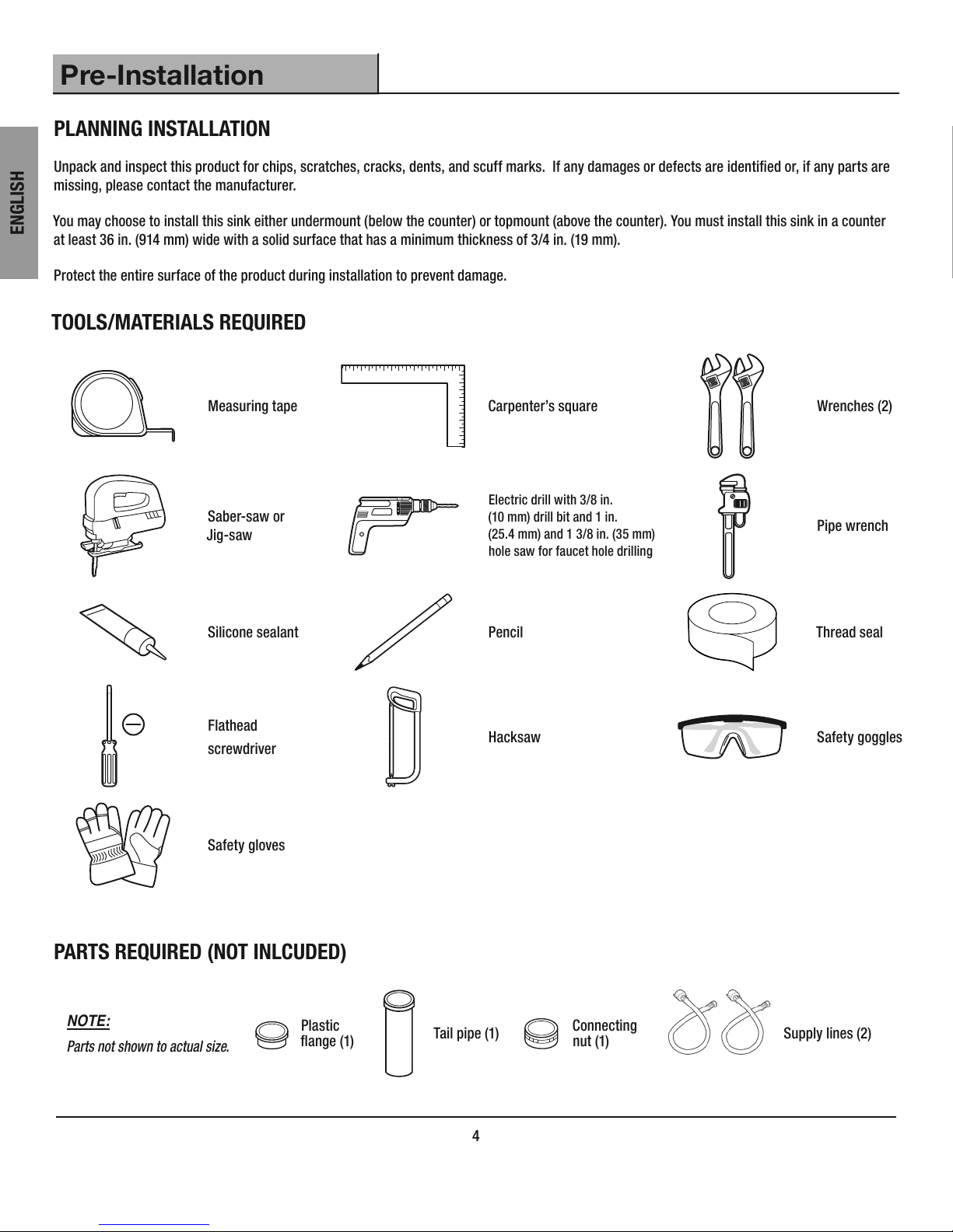
TOOLS/MATERIALS REQUIRED
Measuring tape Carpenter’s square Wrenches (2)
Electric drill with 3/8 in.
Saber-saw or
Jig-saw
(10 mm) drill bit and 1 in.
(25.4 mm) and 1 3/8 in. (35 mm)
hole saw for faucet hole drilling
Pipe wrench
Silicone sealant Pencil Thread seal
Flathead
screwdriver
Safety gloves
PARTS REQUIRED (NOT INLCUDED)
NOTE:
Parts not shown to actual size.
Plastic
ange (1)
Tail pipe (1)
Hacksaw Safety goggles
Connecting
nut (1)
Supply lines (2)
4
Pre-Installation (continued)
1A
B
A
C D
E
F
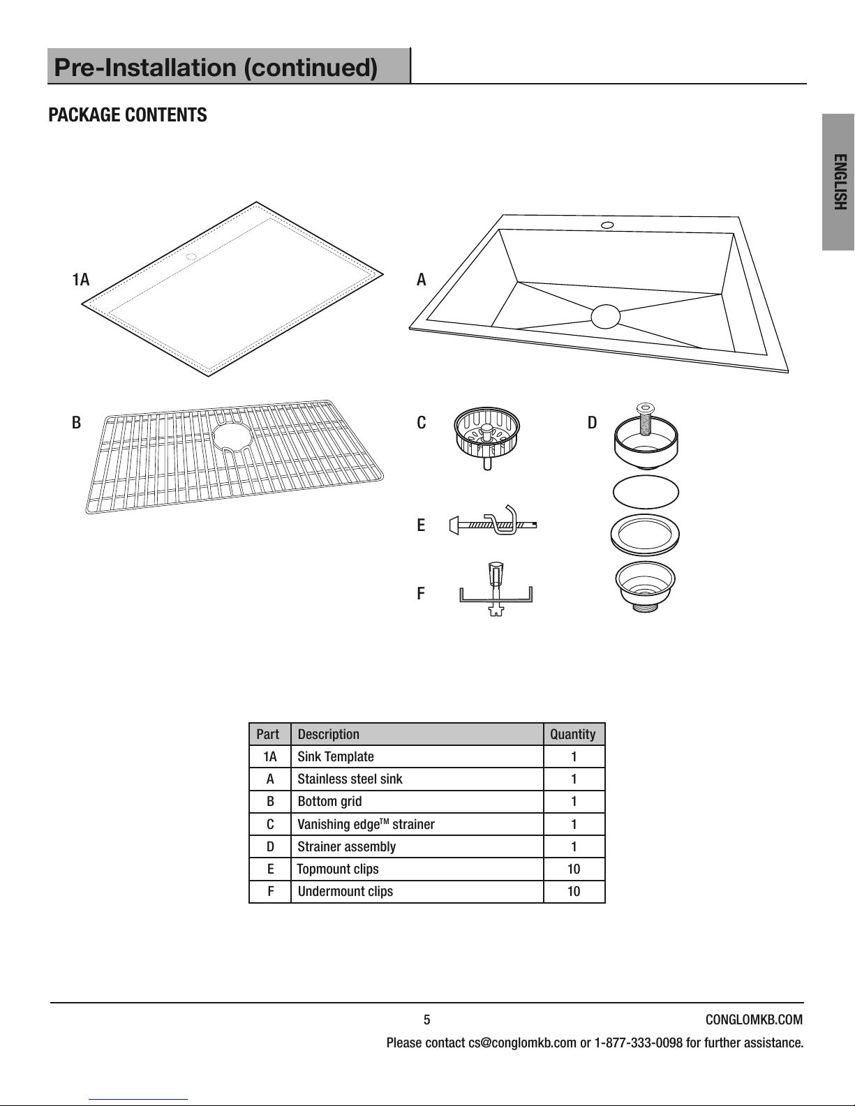
PACKAGE CONTENTS
ENGLISH
Part Description Quantity
1A Sink Template 1
A Stainless steel sink 1
B Bottom grid 1
C Vanishing edgeTM strainer 1
D Strainer assembly 1
E Topmount clips 10
F Undermount clips 10
5 CONGLOMKB.COM
Please contact cs@conglomkb.com or 1-877-333-0098 for further assistance.
Installation
UNDERMOUNT INSTALLATION
PREPARING THE AREA CUTTING THE COUNTER
NOTE:
ENGLISH
Undermount sinks are mounted from below the counter. If you
are installing a topmount or “drop-in” sink, please see “topmount
installation” on page 9.
It is highly recommended that undermounting be performed
by a professional installer. Improper installation will void the
warranty. Sink template (1A) shows cut-lines for both undermount
and topmount installations. Review it carefully and follow the
undermount cut-lines only to install the sink under your counter.
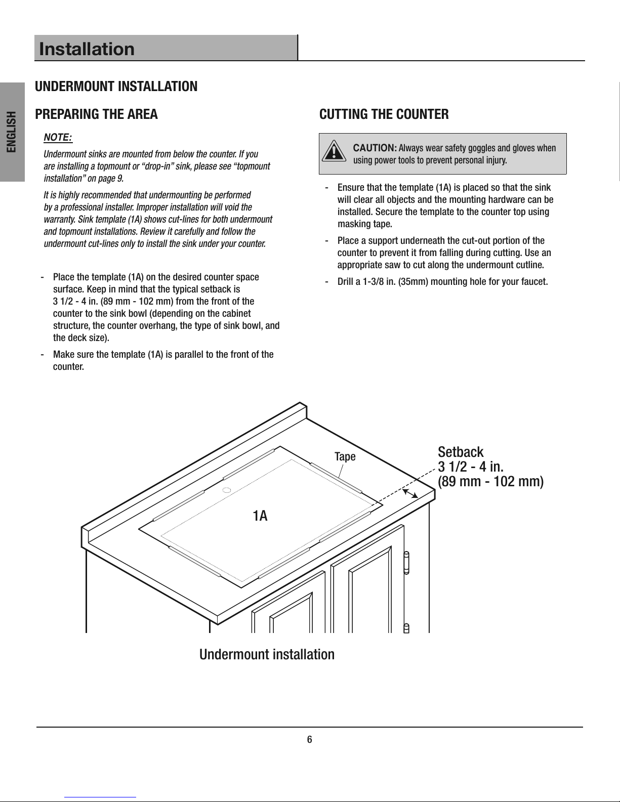
- Place the template (1A) on the desired counter space
surface. Keep in mind that the typical setback is
3 1/2 - 4 in. (89 mm - 102 mm) from the front of the
counter to the sink bowl (depending on the cabinet
structure, the counter overhang, the type of sink bowl, and
the deck size).
- Make sure the template (1A) is parallel to the front of the
counter.
CAUTION: Always wear safety goggles and gloves when
using power tools to prevent personal injury.
- Ensure that the template (1A) is placed so that the sink
will clear all objects and the mounting hardware can be
installed. Secure the template to the counter top using
masking tape.
- Place a support underneath the cut-out portion of the
counter to prevent it from falling during cutting. Use an
appropriate saw to cut along the undermount cutline.
- Drill a 1-3/8 in. (35mm) mounting hole for your faucet.
1A
Undermount installation
6
Tape
Setback
3 1/2 - 4 in.
(89 mm - 102 mm)
Installation (continued)
15.8 mm
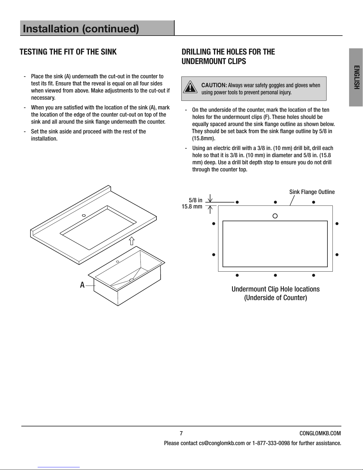
TESTING THE FIT OF THE SINK
- Place the sink (A) underneath the cut-out in the counter to
test its t. Ensure that the reveal is equal on all four sides
when viewed from above. Make adjustments to the cut-out if
necessary.
- When you are satised with the location of the sink (A), mark
the location of the edge of the counter cut-out on top of the
sink and all around the sink ange underneath the counter.
- Set the sink aside and proceed with the rest of the
installation.
DRILLING THE HOLES FOR THE
UNDERMOUNT CLIPS
CAUTION: Always wear safety goggles and gloves when
using power tools to prevent personal injury.
- On the underside of the counter, mark the location of the ten
holes for the undermount clips (F). These holes should be
equally spaced around the sink ange outline as shown below.
They should be set back from the sink ange outline by 5/8 in
(15.8mm).
- Using an electric drill with a 3/8 in. (10 mm) drill bit, drill each
hole so that it is 3/8 in. (10 mm) in diameter and 5/8 in. (15.8
mm) deep. Use a drill bit depth stop to ensure you do not drill
through the counter top.
Sink Flange Outline
5/8 in
ENGLISH
A
Undermount Clip Hole locations
(Underside of Counter)
7 CONGLOMKB.COM
Please contact cs@conglomkb.com or 1-877-333-0098 for further assistance.
Installation (continued)
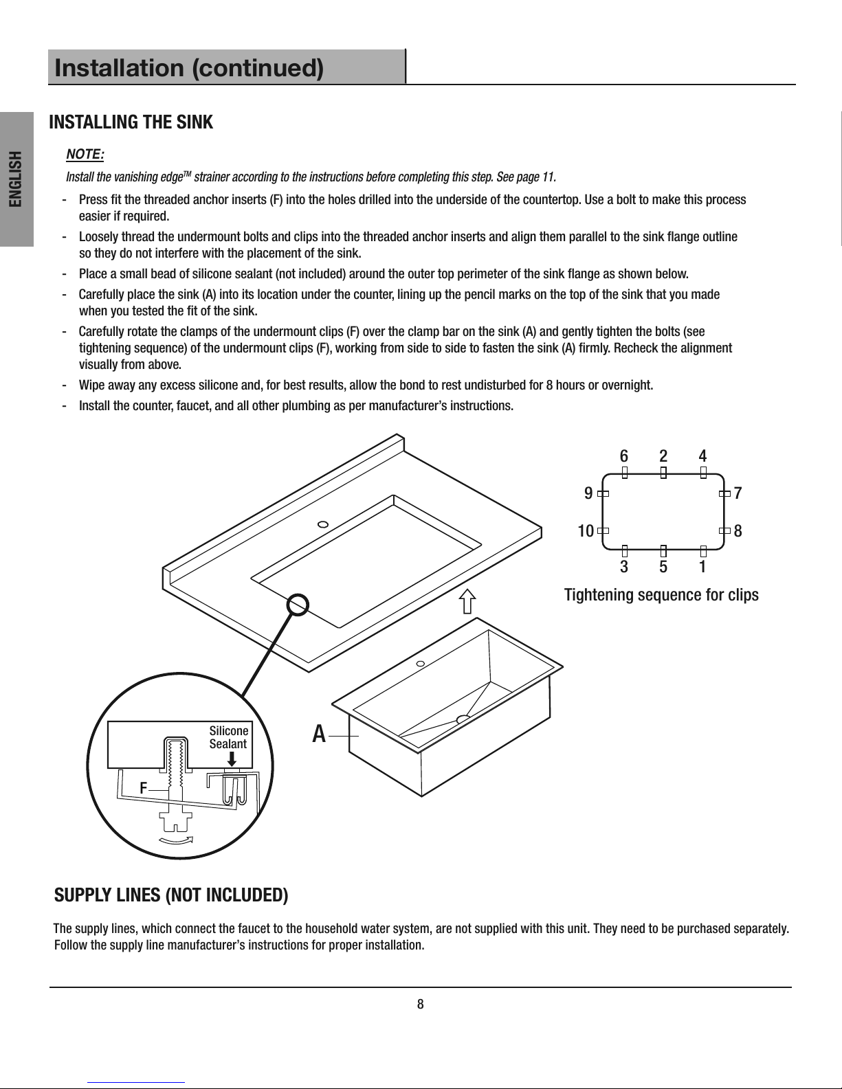
INSTALLING THE SINK
NOTE:
Install the vanishing edgeTM strainer according to the instructions before completing this step. See page 11.
ENGLISH
- Press t the threaded anchor inserts (F) into the holes drilled into the underside of the countertop. Use a bolt to make this process
easier if required.
- Loosely thread the undermount bolts and clips into the threaded anchor inserts and align them parallel to the sink ange outline
so they do not interfere with the placement of the sink.
- Place a small bead of silicone sealant (not included) around the outer top perimeter of the sink ange as shown below.
- Carefully place the sink (A) into its location under the counter, lining up the pencil marks on the top of the sink that you made
when you tested the t of the sink.
- Carefully rotate the clamps of the undermount clips (F) over the clamp bar on the sink (A) and gently tighten the bolts (see
tightening sequence) of the undermount clips (F), working from side to side to fasten the sink (A) rmly. Recheck the alignment
visually from above.
- Wipe away any excess silicone and, for best results, allow the bond to rest undisturbed for 8 hours or overnight.
- Install the counter, faucet, and all other plumbing as per manufacturer’s instructions.
6 2 4
9
7
810
3 5 1
Tightening sequence for clips
Silicone
Sealant
F
A
SUPPLY LINES (NOT INCLUDED)
The supply lines, which connect the faucet to the household water system, are not supplied with this unit. They need to be purchased separately.
Follow the supply line manufacturer’s instructions for proper installation.
8
 Loading...