

Page 1
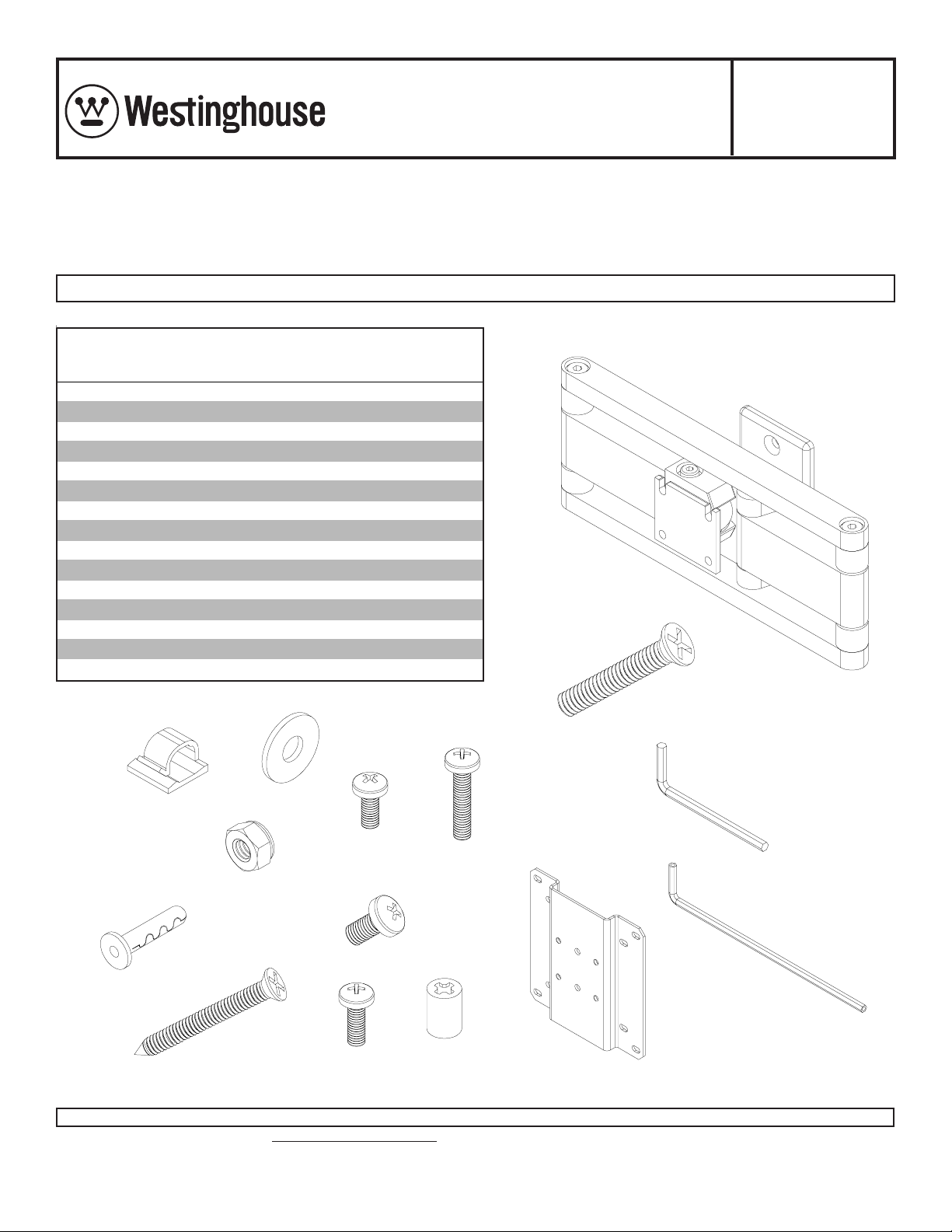
Installation and Assembly Vision•Point™ Articulating Wall Arm/
Model: MT25 ARM18
Patent Pending
Cabinet Side mount for LCD screens
Provides full swivel capability around the side of a cabinet for screens 10" to 15" wide.
Note: Read entire instruction sheet before you start installation and assembly . Max. Load Capacity:
25 lb (11.3 kg)
T o mount to met al studs, order metal stud accessory kit ACC 908.
Parts List
Descri p tion Qty. Part #
wall arm as sembly 1 095-0188
A
cable c l i p 2 590-2155
B
1/4- 20 x 1.5 " fl at head s crew 2 520-2164
C
.25" ID x .75" OD washer 2 540-2015
D
1/4- 20 n ylock nu t 2 530-2002
E
M5 x .8 x 10 mm phil li ps sc rew 4 520-2005
F
3/16" all e n wrench 1 560-0071
G
All i gat or® concret e anc hor 2 590-0097
H
#14 x 2.5" fl at head wood s crew 2 520-2165
I
4 mm al l en wrench 1 560-9706
J
M4 x .7 x 12 mm phil li ps sc rew 4 504-2013
K
adapter brack et 1 095-4101
L
M4 x .7 x 10 mm phil li ps sc rew 4 520-2027
M
M4 x .7 x 20 mm phil li ps sc rew 4 504-2014
N
.198" x .313" x . 437" H retai ni ng s pac er 4 590-5003
O
C
A
D
B
M
N
G
E
F
H
J
I
K
Visit the Westinghouse Web Site at www.westinghousedigital.com For customer service call 1-866-287-5555.
O
L
ISSUED: 04-22-04 SHEET #: 095-9195-11 of 8
Page 2
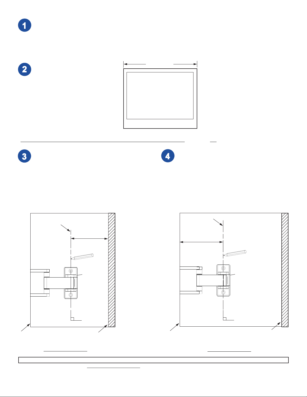
For mounting to side of cabinet start with step 2. For mounting to wall start with step 7.
WIDTH OF
Measure the width of your screen.
SCREEN
Note: The dimension of half the
width will be used for steps 3 and 4.
For mounting to the side of a kitchen or bathroom cabinet – follow all steps below:
T o ensure the screen does not hit the wall when
the arm is in the closed position and mounted to
the side of your cabinet, do the following:
Measure 1/2 the width of your screen and
subtract 3/4". This dimension is the minimum
space you need between the back wall and the
wall plate mounting holes. This is shown by line
"A" in the illustration below. Draw line "A" on
your cabinet using a pencil.
LINE "A"
HALF WIDTH - 3/4"
WALL PLATE
Note: Make both
lines "A" & "B" at a
90° angle with the
cabinet.
If you would like your screen to swivel the full 180°
over the outer edge of your cabinet, do the
following:
Measure 1/2 the width of your screen and add 1 3/8".
This is the maximum space you need between
the outer edge of your cabinet and the wall plate
mounting holes. This is shown with line "B" in the
illustration below. Draw line "B" on your cabinet
using a pencil.
LINE "B"
HALF WIDTH + 1 3/8"
WALL PLATE
90°
OUTER EDGE
OF CABINET
BACK WALL
Side of Cabinet
Visit the Westinghouse Web Site at www.westinghousedigital.com For customer service call 1-866-287-5555.
OUTER EDGE
OF CABINET
Side of Cabinet
ISSUED: 04-22-04 SHEET #: 095-9195-12 of 8
90°
BACK WALL
Page 3
The depth of the cabinet and the size of your screen will determine which line "A" or "B" is closer to the outer
edge of the cabinet. Use the line closer to outer edge of your cabinet as your centerline. This will ensure 180°
of swivel around the side of your cabinet and that your screen will not hit the back wall in the closed position.
Use wall plate as template to mark center of holes onto side of
cabinet along centerline.
Make sure wall plate is level, then drill two 9/32" (7 mm) holes
where marked.
BACK WALL
OUTER EDGE
OF CABINET
CENTERLINE
Side of Cabinet
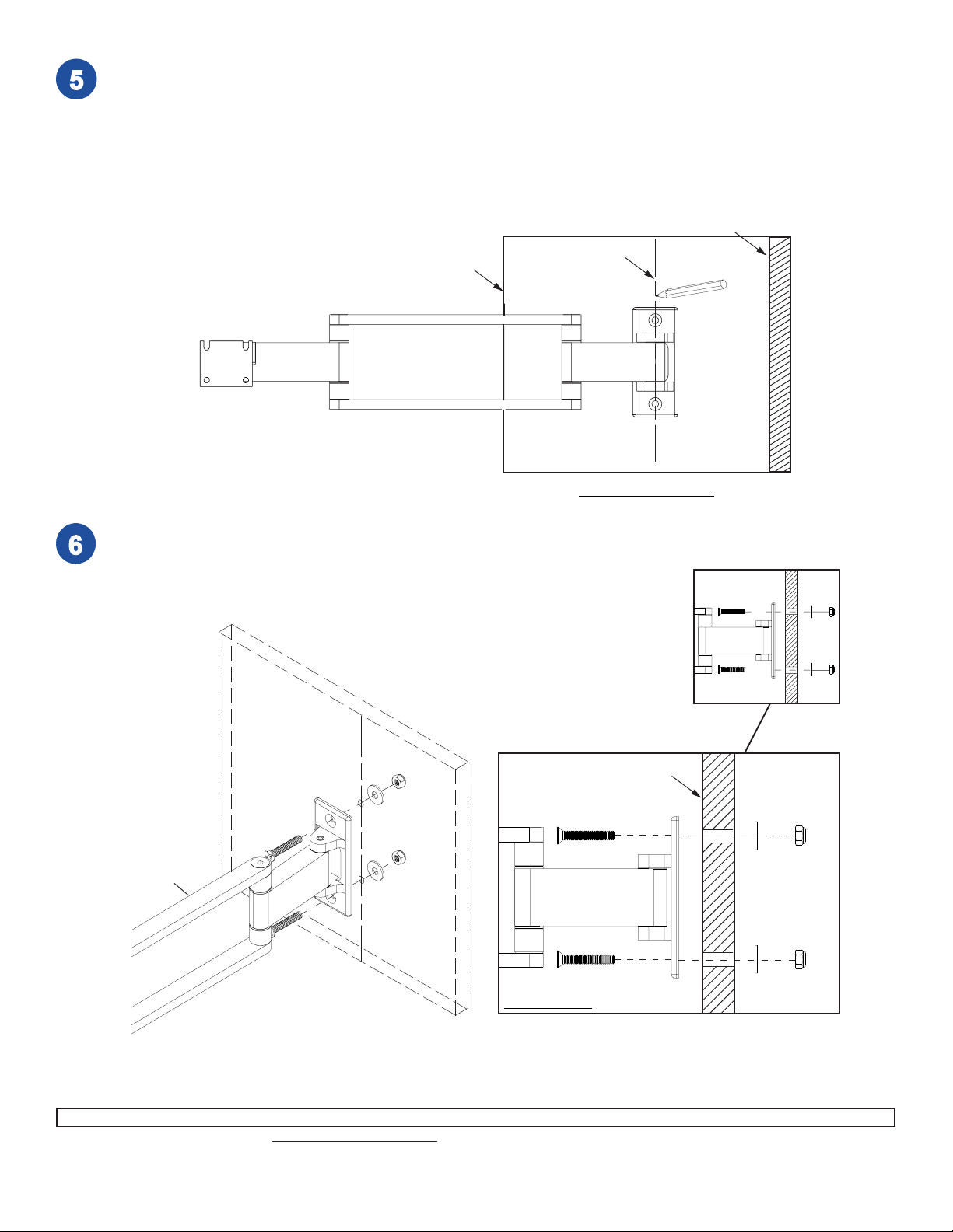
Fasten wall arm assembly (A) to side of cabinet using two 1/4-20 flat head screws (C),
washers (D), and 1/4-20 nylock nuts (E) as shown below .
Skip to step 9.
CABINET
A
C
D
E
A
Side View
ISSUED: 04-22-04 SHEET #: 095-9195-13 of 8
Visit the Westinghouse Web Site at www.westinghousedigital.com For customer service call 1-866-287-5555.
Page 4

WARNING
• When installing wall mounts on cinder block, verify that you have a minimum of 1-3/8" of actual concrete surface in
the hole to be used for the concrete anchors. Do not drill into mortar joints! Be sure to mount in a solid part of the
block, generally 1" minimum from the side of the block. Cinder block must meet ASTM C-90 specifications. It is
suggested that a standard electric drill on slow setting is used to drill the hole instead of a hammer drill to avoid
breaking out the back of the hole when entering a void or cavity .
• Concrete must be 2000 psi density minimum. Lighter density concrete may not hold concrete anchor .
• Make sure that the wall will safely support four times the combined load of the equipment and all attached hardware and components.
For Cinder Block and Concrete Walls, drill one 1/4"
(6 mm) dia. hole to a minimum depth of 2" (51 mm).
Insert anchor (H) in hole flush with wall as shown in fig
1.1 on next page. Place wall plate over anchor (H) and
secure with wood screw (I) as shown in figure 1.2. Make
sure wall plate is level, mark other hole and repeat steps
with other fasteners. Tighten all fasteners. See figure
1.3.
Skip to step 9.
WARNING
• Tighten concrete anchor bolts firmly, but do not
overtighten. Overtightening can damage the bolts,
greatly reducing their holding power.
• Never tighten in excess of 80 in • lb (9 N.M.).
WARNING
• Concrete anchors are not intended for attachment to
concrete wall covered with a layer of plaster, drywall,
or other finishing material. If mounting to concrete wall
covered with plaster/drywall is unavoidable, plaster/
drywall (up to 5/8" thick) must be counterbored as
shown below. If plaster/drywall is thicker than 5/8",
custom fasteners must be supplied by installer .
fig 1.1
CONCRETE
WALL
H
Drill hole and insert anchor (H).
fig 1.2
WALL PLATE
I
H
Place wall plate over anchor (H) and secure with screw (I).
fig 1.3
After repeating figure 1.1, tighten all fasteners.
I
H
CUT AW A Y VIEW
WALL
PLA TE
ISSUED: 04-22-04 SHEET #: 095-9195-14 of 8
Visit the Westinghouse Web Site at www.westinghousedigital.com For customer service call 1-866-287-5555.
Page 5

For Wood Stud Walls, use a stud finder to locate
center of stud. Make sure wall plate is level, drill two
3/16" (5 mm) dia. holes to a minimum depth of 2"
(51 mm). Attach wall plate to center of wood stud
using two #14 wood screws (I).
WOOD
STUD
WALL
WARNING
WALL
PLA TE
• Tighten wood screws so that wall plate is firmly
attached, but do not overtighten. Overtightening can
damage the screws, greatly reducing their holding
power.
• Never tighten in excess of 80 in • lb (9 N.M.).
I
• Make sure that mounting screws are anchored into the
center of the studs. The use of an "edge to edge" stud
finder is highly recommended.
Note: This product is designed to accommodate screens with VESA® compliant hole pattern. For safe
mounting, please make sure that mounting screws turn at least three complete turns in the screen inserts.
FOR VESA 75 MOUNTING PATTERN:
1) Choose hole pattern indicated below. 2) Attach
adapter bracket (L) to back of screen using four
10 mm screws (M) as indicated below. 3) If hole
pattern is in a pocket, attach adapter bracket (L)
to back of screen using four 20 mm screws (N)
and four retaining spacers (O) as indicated below.
FOR VESA 100 MOUNTING PATTERN:
1) Choose hole pattern indicated below. 2) Attach adapter
bracket (L) to back of screen using four M4 x 10 mm
screws (M) as indicated below.
Note: If you don't get three complete turns in the screen
inserts, use four M4 x 12 mm screws (K) instead of four
M4 x 10 mm screws (M).
For screens with a hole
L
Visit the Westinghouse Web Site at www.westinghousedigital.com For customer service call 1-866-287-5555.
pattern in a pocket,
spacers (O) go between
adapter bracket (L) and
screen.
Note: LCD screen may
appear slightly different
than illustrated.
L
ISSUED: 04-22-04 SHEET #: 095-9195-15 of 8
Page 6

Note: If the balljoint feels loose or
too easy to adjust, slightly tighten
cap socket screw until balljoint feels
firmly in place.
Insert two M5 x 10 mm screws (F)
into top two holes of adapter bracket
(L) leaving approximately 1/4" of
exposed thread. With slots facing
upward, hook screws onto wall arm
balljoint as shown in figure 2.1.
Insert two M5 screws (F) through
bottom holes of wall arm balljoint
into adapter bracket (L) as shown in
figure 2.2.
Tighten all screws (F).
T o obt ain full range of motion and enough tension to hold the screen in any position, simply tighten or loosen cap
socket screw a few turns using 4 mm allen wrench (J).
fig 2.1
F
WALL ARM
BALL JOINT
fig 2.2
L
L
1/4"
F
CAP SOCKET
SCREW
CAUTION
• Do not remove screw or loosen screw until it is no
longer engaged with the mount. Doing so may cause
the screen to fall.
CAP SOCKET SCREW
ISSUED: 04-22-04 SHEET #: 095-9195-16 of 8
Visit the Westinghouse Web Site at www.westinghousedigital.com For customer service call 1-866-287-5555.
Page 7

If more or less tension is desired in the arm pivot points, do the following:
• To increase tension, turn socket screw clockwise with 3/16" allen wrench (G).
• To reduce tension, turn socket screw counterclockwise with allen wrench (G). Do not turn more than half a
turn.
SOCKET SCREWS
Place cable clips (B) as needed, to better manage cords, making sure that one clip is
close enough to the hinge area to prevent cord from bunching up.
Note: Make sure cords have enough slack to allow full movement of the arm.
B
ISSUED: 04-22-04 SHEET #: 095-9195-17 of 8
Visit the Westinghouse Web Site at www.westinghousedigital.com For customer service call 1-866-287-5555.
Page 8

Limited Five-Year Warranty
Westinghouse Digital Electronics warrants to original end-users of this Westinghouse television mounting product (the
“Product”) that the Product will be free from defects in material and workmanship, under normal use, for a period of five (5)
years from the date of purchase by the original end-user, subject to the following terms and conditions:
REP AIR OR REPLACEMENT – For a period of five (5) years from the original date of purchase, W estinghouse Digit al
Electronics will repair any defect in material or workmanship in the Product, or , at its option, replace a defective Product.
Replacement parts and products will be warranted for either the remainder of the original warranty period or ninety (90)
days from the date of delivery to the end-user, whichever occurs last.
OBT AINING WARRANTY SER VICE – To obt ain warranty services, you must either personally deliver or ship the Product
to Westinghouse Digital Electronics, freight prepaid. Please call Westinghouse Digital Electronics at (866) 287-5555 to
obtain a Return Merchandise Authorization (“RMA”) and for other instructions regarding return and replacement or repair of
the Product. Westinghouse Digital Electronics will not accept Products delivered to it without an RMA.
EXCLUSIONS TO W ARRANTY – This warranty does not cover damage caused by (a) service or repairs by anyone other
than personnel authorized by Westinghouse Digital Electronics, (b) the failure to utilize proper packing when returning the
product, (c) improper installation or the failure to follow Product instructions or warnings, or (d) misuse or accident, in
transit or otherwise.
PROOF OR ORIGINAL PURCHASE – A sales receipt, invoice, or other proof of purchase specifying the original date of
purchase within the five (5) year warranty period must be presented to obtain warranty service. This warranty extends to
the original purchaser and is not transferable.
EITHER REP AIR OR REPLACEMENT IS YOUR EXCLUSIVE REMEDY UNDER THIS WARRANTY. EXCEPT TO THE
EXTENT PROHIBITED BY LAW, WESTINGHOUSE DIGITAL SHALL NOT BE LIABLE FOR ANY INCIDENTAL OR
CONSEQUENTIAL DAMAGES CLAIMED T O ARISE FROM BREACH OF ANY EXPRESS OR IMPLIED W ARRANTY ON
THIS PRODUCT . ANY IMPLIED WARRANTY OF MERCHANT ABILITY OR FITNESS FOR A P ARTICULAR PURPOSE
ON THIS PRODUCT IS LIMITED IN DURA TION AND SCOPE TO THE TERMS OF THIS W ARRANTY .
Some States do not allow the exclusion or limit ation of incidental or consequential damages, or allow limitations on how
long an implied warranty lasts, so the above limitation may not apply to you. This warranty gives specific legal rights, and
you may also have other rights which vary from S tate to S tate.
Westinghouse Digital Electronics, LLC
16257 East Gale A ve.
City of Industry , California 91745
T el: (626) 333-9677.
ISSUED: 04-22-04 SHEET #: 095-9195-18 of 8
Visit the Westinghouse Web Site at www.westinghousedigital.com For customer service call 1-866-287-5555.
and Westinghouse are trademarks of Westinghouse Electric Corporation and are used under license.
 Loading...