

Page 1

AC System Installation Guide
V2 60 Cell Modules
Rev: 10-12-11
Page 2

Westinghouse Solar AC Installation Guide
Copyright © 2011. Westinghouse Solar. All rights reserved.
No part of this publication may be reproduced, stored in a retrieval system or transmitted in any form or by any
means, electronic, mechanical, photocopying, recording, scanning or otherwise, except as permitted under Section
107 or 108 of the 1976 U.S. Copyright Act, without prior written permission from an officer of Westinghouse Solar.
For permission contact: Westinghouse Solar, 1475 South Bascom Ave. Suite 101, Campbell, CA 95008, Attn: VP of
Marketing.
Trademarks: Westinghouse Solar, Westinghouse Solar Power Systems, Sun for Everyone, and related trade dress
are trade names, trademarks or registered trademarks, and may not be used without written permission.
LIMITATION OF LIABILITY/DISCLAIMER OF WARRANTY. WESTINGHOUSE SOLAR, ITS PARENT, SUBSIDIARIES,
AND THEIR EMPLOYEES, AGENTS, OFFICERS AND DIRECTORS (COLLECTIVELY “AUTHOR”) MAKE NO
REPRESENTATIONS OR WARRANTIES WITH RESPECT TO THE ACCURACY OR COMPLETENESS OF THE CONTENTS
OF THIS WORK AND SPECIFICALLY DISCLAIM ALL WARRANTIES, INCLUDING WITHOUT LIMITATION WARRANTIES
OF FITNESS FOR A PARTICULAR PURPOSE. NO WARRANTY MAY BE CREATED OR EXTENDED BY SALES,
PROMOTIONAL MATERIALS OR CUSTOMER SERVICE. THE ADVICE AND STRATEGIES CONTAINED HEREIN MAY
NOT BE SUITABLE FOR EVERY SITUATION. THE CONTENTS OF THIS WORK ARE INTENDED FOR A TARGET
AUDIENCE THAT HAS SOME BASIC CONSTRUCTION AND ELECTRICAL WIRING KNOWLEDGE. THIS WORK IS SOLD
WITH THE UNDERSTANDING THAT THE AUTHOR IS NOT ENGAGED IN RENDERING LEGAL, ACCOUNTING, OR
OTHER PROFESSIONAL SERVICES. IF PROFESSIONAL ASSISTANCE IS REQUIRED, THE SERVICES OF A COMPETENT
PROFESSIONAL PERSON SHOULD BE SOUGHT. IN VIEW OF THE CHANGES IN LOCAL, STATE AND FEDERAL
REGULATIONS, THE READER IS URGED TO REVIEW AND EVALUATE THE INFORMATION PROVIDED BY THEIR
LOCAL, STATE AND FEDERAL REGULATORY AUTHORITY FOR, AMONG OTHER THINGS, ANY RULES, REGULATIONS,
INSTRUCTIONS, REQUIREMENTS, OR PRECAUTIONS RELATED TO THE INSTALLATION OF PV SOLAR ELECTRIC
SYSTEMS. READERS SHOULD CONSULT A LICENSED SOLAR INSTALLATION CONTRACTOR OR ELECTRICIAN WHERE
APPROPRIATE. THE AUTHOR SHALL NOT BE LIABLE FOR DAMAGES ARISING HEREFROM.
Place of Origin. This manual, and the techniques, methods and IP contained within it, were created in the United
States of America. Westinghouse Solar AC Systems contain some foreign made components. Assembly, design and
distribution takes place through operations located within and outside the United States of America.
Protected by U.S. patents (7,406,800; 7,832,157, 7,866,098 and 7,987,641), and foreign patents (2,005,248,343;
243,626; 274,182 and 751,614). Other patents pending.
Copyright © 2011 - Westinghouse Solar
Page 3

Westinghouse Solar AC Installation Guide
Table of Contents
Section I. Getting Started ...................................................................................................................1
1. Safety Precautions ............................................................................................................................ 1
2. Parts and Tools .................................................................................................................................. 1
3. Solar Power Basics ............................................................................................................................ 2
4. Using this Guide ................................................................................................................................ 3
Section II. Westinghouse Solar AC System Layout and Design ..............................................................5
1. Westinghouse Solar Roof Layout Site Surveys .................................................................................. 7
2. Drafting a Roof Layout ...................................................................................................................... 7
3. Elements of Designing a Solar System Specific to Westinghouse Solar AC Panels........................... 8
4. Westinghouse Solar Mounting and Structural Requirements ........................................................ 10
5. Drafting a Solar Array ...................................................................................................................... 12
Section III. Creating an Electrical Diagram ........................................................................................ 14
1. Westinghouse Solar AC Electrical Requirements ............................................................................ 14
2. Single line diagram preparation ...................................................................................................... 15
3. Electrical Line Diagram .................................................................................................................... 16
4. Grounding ....................................................................................................................................... 16
Section IV. Installation ..................................................................................................................... 18
1. Safety Warnings .............................................................................................................................. 18
2. Layout .............................................................................................................................................. 18
3. Mounting ......................................................................................................................................... 21
4. Module Installation ......................................................................................................................... 23
5. Connecting Westinghouse Solar AC Wiring Harnesses ................................................................... 26
Copyright © 2011 - Westinghouse Solar
Page 4

Westinghouse Solar AC Installation Guide
6. Grounding ....................................................................................................................................... 29
7. Adding AC Interconnect Parts ......................................................................................................... 30
8. Commissioning Westinghouse Solar AC Systems ........................................................................... 31
Section V. Westinghouse Solar Operations ....................................................................................... 33
1. Troubleshooting .............................................................................................................................. 33
2. Troubleshooting an Inoperable Inverter (For Experienced Installers) ............................................ 34
3. Disconnecting the Inverter from the PV Panel ............................................................................... 34
Section VI. Definitions ...................................................................................................................... 35
Section VII. Appendix ......................................................................................................................... i
Section VIII. Technical Support ........................................................................................................ xiii
Table of Figures .............................................................................................................................. xiv
Copyright © 2011 - Westinghouse Solar
Page 5
Westinghouse Solar AC Installation Guide
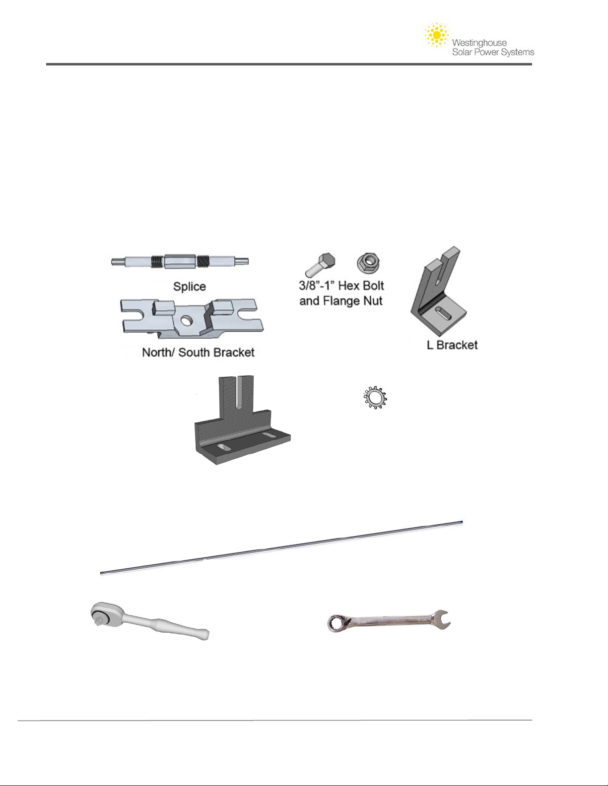
Splice Driver
1/4” Ratchet Wrench
9/16” Combination Wrench
Section I. Getting Started
1. Safety Precautions
• Before installing the Westinghouse Solar AC Module, read all instructions and cautionary
markings in the Westinghouse Solar AC documentation.
• Perform all electrical installations in accordance with all local electrical codes, the National
Electrical Code (NEC), ANSI/NFPA 70 and local utility requirements.
2. Parts and Tools
Required tools include:
Splice Driver (WHS provided)
Grounding Washer
Offset Bracket
(Available from Westinghouse Solar)
(Available from any tool source)
Copyright © 2011 - Westinghouse Solar 1 | Page
(available from any tool source)
Page 6
Westinghouse Solar AC Installation Guide
3. Solar Power Basics
Background
Rooftop solar power systems have come a long way, and Westinghouse Solar AC panels break new
ground in both performance and safety. Westinghouse Solar AC panels are the first solar panel on
the market to integrate racking, wiring, grounding and inverters directly into the panel. This
section provides an overview of the installation and operation of your Westinghouse Solar Power
System. Please note that the instructions herein are directed towards individuals and
professionals with good knowledge of residential wiring and construction techniques. Do not
undertake the wiring and installation of this product if you are not qualified to work with
household AC voltages, if you are not knowledgeable about construction techniques, and if you
are not experienced in working on rooftops and other dangerous locations.
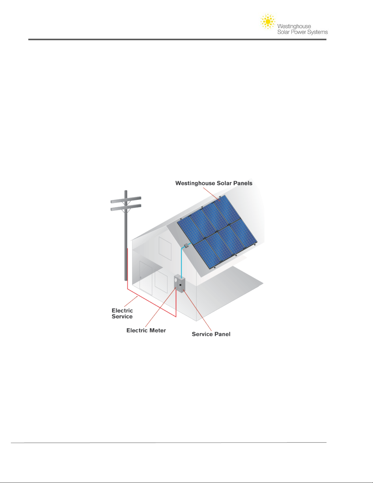
Figure 1 -– Westinghouse Solar AC System
How Westinghouse Solar AC Works
Westinghouse Solar AC panels are installed on a sunny, generally south-facing rooftop or back
yard area. AC output from the solar panels is wired into your home’s electrical service panel via a
dedicated 240 VAC branch circuit. When direct sunlight hits Westinghouse Solar panels, their
built-in inverters produce AC power synchronized to the utility’s grid. This power goes towards use
in your home first. When you produce more electricity on your roof than your home needs, the
excess flows to the grid, running your electric meter backwards. At night or on cloudy days you
Copyright © 2011 - Westinghouse Solar 2 | Page
Page 7

Westinghouse Solar AC Installation Guide
still draw power from your utility. Your electric bill is reduced because you only pay for the net
amount of electricity you use.
Westinghouse Solar AC Panel Design and Performance
Ordinary solar power systems use a centralized inverter, and require the installation of a separate
racking system to mount the panels. These ordinary systems also require manual interconnection
of high voltage DC wiring, and manual grounding of all panel and racking components. With the
racking, wiring, grounding and inverters built into Westinghouse Solar panels, installation is much
easier, reliability is greater and performance is 5 to 25% higher than ordinary systems.
The rating on each panel indicates the nominal DC power output in watts of a panel when it is in
bright sunlight in 25 degree C conditions, and the sun’s rays are perpendicular to the surface of
the panel. Because the inverter operates at about 95% efficiency, the AC output of the system will
be approximately 5% less than the peak DC output. So at peak conditions, a 235 watt
Westinghouse Solar AC panel will produce up to about 223 watts of power. In real world
conditions throughout the day, as the sun rises, moves across the sky, and then sets, the output of
the panels will increase from essentially zero at dawn to a peak of about 175-214 watts
(depending on season, sun angle, mounting angle and roof orientation), and then decline again to
zero. Each panel operates independently, so if one is shaded or dirty the adjacent panels will still
operate to maximize their energy output.
Westinghouse Solar AC panels use Enphase micro-inverters, which are mounted on the back of
each panel. The easiest way to determine the output from your Westinghouse Solar AC panels is
with the optional Energy Management Unit (EMU). The EMU communicates with Enphase’s
“Englighten” website for real time reporting and analysis on the performance of each of your
Westinghouse Solar panels. The EMU is installed by plugging it into any convenient 120 VAC wall
socket and providing an Ethernet connection to your broadband router or modem. After
installation of the EMU, the full network of Westinghouse Solar AC Panels automatically begins
reporting to Enlighten. Alternatively, you may measure the voltage, current and power output of
each branch circuit of Westinghouse Solar AC panels with conventional electrical instruments,
taking the appropriate cautions when handling live electrical circuitry.
4. Using this Guide
This guide will familiarize you with the fundamentals of design and installation of your
Westinghouse Solar Power System. The guide also serves to illustrate the simplicity and
efficiency of solar design when equipment is developed in unison with each other. Westinghouse
Solar Power Systems consist of hundreds of individual separate parts built into one integrated
solar electric system delivering easier, faster design and installation over ordinary solar
installations.
This guide contains three primary sections. The first section covers the physical properties of solar
design specific to the Westinghouse Solar Power System, including how to layout your
Westinghouse Solar Power System, how to choose components, and the structural requirements
Copyright © 2011 - Westinghouse Solar 3 | Page
Page 8

Westinghouse Solar AC Installation Guide
involved in the installation process. The second section of this guide covers the creation of an
electrical diagram, electrical site surveys, and elements of designing a solar system specific to
Westinghouse Solar AC panels. Common requirements for solar electrical permit applications are
also reviewed. The final section reviews Westinghouse Solar AC installation best practices and
system commissioning. If you are familiar with residential construction techniques, AC wiring, and
your local permitting requirements you will have the basic skills to install your Westinghouse Solar
Power System. Please note that certain state incentive programs and utility interconnection
regulations may require skills and instruments beyond those noted above, in which case the
services of a professional solar installer may be needed.
The convention we use to describe the orientation of Westinghouse Solar layouts in this guide is
that the north/ south direction describes rows of panels that are aligned vertically where north is
the peak of the roof, and south refers to the gutter. An east / west row describes a horizontal
grouping of panels from left to right. There are different functions that need to be considered
when designing Westinghouse Solar in regards to the horizontal and vertical connection of panels.
Note:
This guide was created by summarizing common requirements of solar design. It serves to prepare
system designers with a basic understanding of the solar design and planning process. Designers are
encouraged to research the specific demands of the permitting jurisdiction and utility governing their
region. Your installation should be performed in full compliance with OSHA safety standards and all
relevant jurisdictional requirements, including if applicable, the U.S. National Electrical Code (“NEC”).
Copyright © 2011 - Westinghouse Solar 4 | Page
Page 9
Westinghouse Solar AC Installation Guide
Section II. Westinghouse Solar AC System Layout and Design
Westinghouse Solar AC systems require 80% fewer parts than ordinary solar systems; the simplicity of
having fewer parts transfers directly into the ease of the design process. Along with the added
efficiencies of Westinghouse Solar AC panels comes a set of unique parameters that need to be
considered when laying out your design. Westinghouse Solar’s racking system is built directly into the
panel frame. When laying out a single row you should visualize the perimeter of the array for your roof
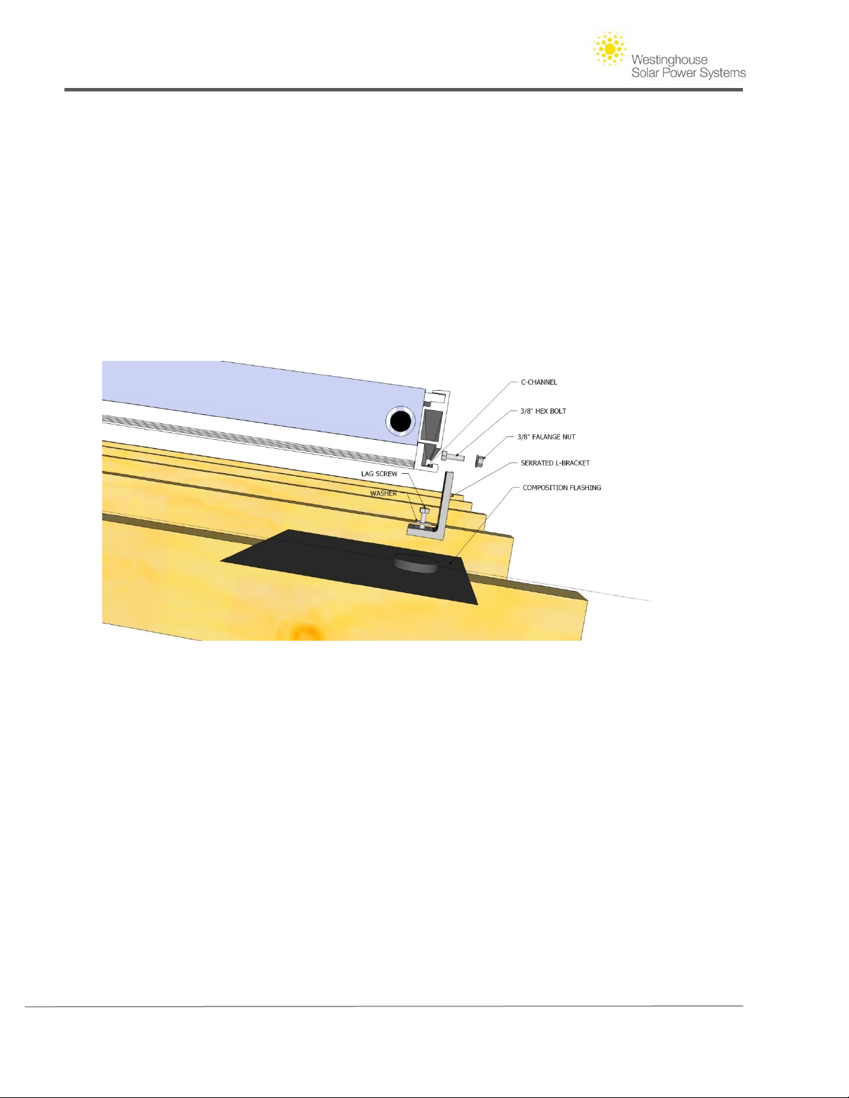
attachment points. The top and bottom frames of Westinghouse Solar panels is where the "Groove”
(Figure 2) is accessible and will serve as connection between the array and the chosen roof-mounting
solution. The Groove provides full adjustability in the east-west direction of your roof, allowing you to
adapt attachment spacing to nearly every rafter scenario.
Figure 2 - Roof attachment component s and panel Groove example for composition shingle roof
You may orient the Westinghouse Solar panels in either a “portrait mode” or a “landscape mode”.
Portrait mode minimizes roof penetrations and AC wiring, resulting in faster installation times.
Landscape mode may also be used for added flexibility. The design of the Westinghouse Solar Power
System also accommodates mixed portrait and landscape installations.
Copyright © 2011 - Westinghouse Solar 5 | Page
Page 10

Westinghouse Solar AC Installation Guide
Figure 3 – Six by two array installed in portrait mode
Figure 4 - Comparably sized four by three array in landscape mode
Copyright © 2011 - Westinghouse Solar 6 | Page
Page 11

Westinghouse Solar AC Installation Guide
1. Westinghouse Solar Roof Layout Site Surveys
Prepare for the roof layout by surveying your roof to gather the following design information:
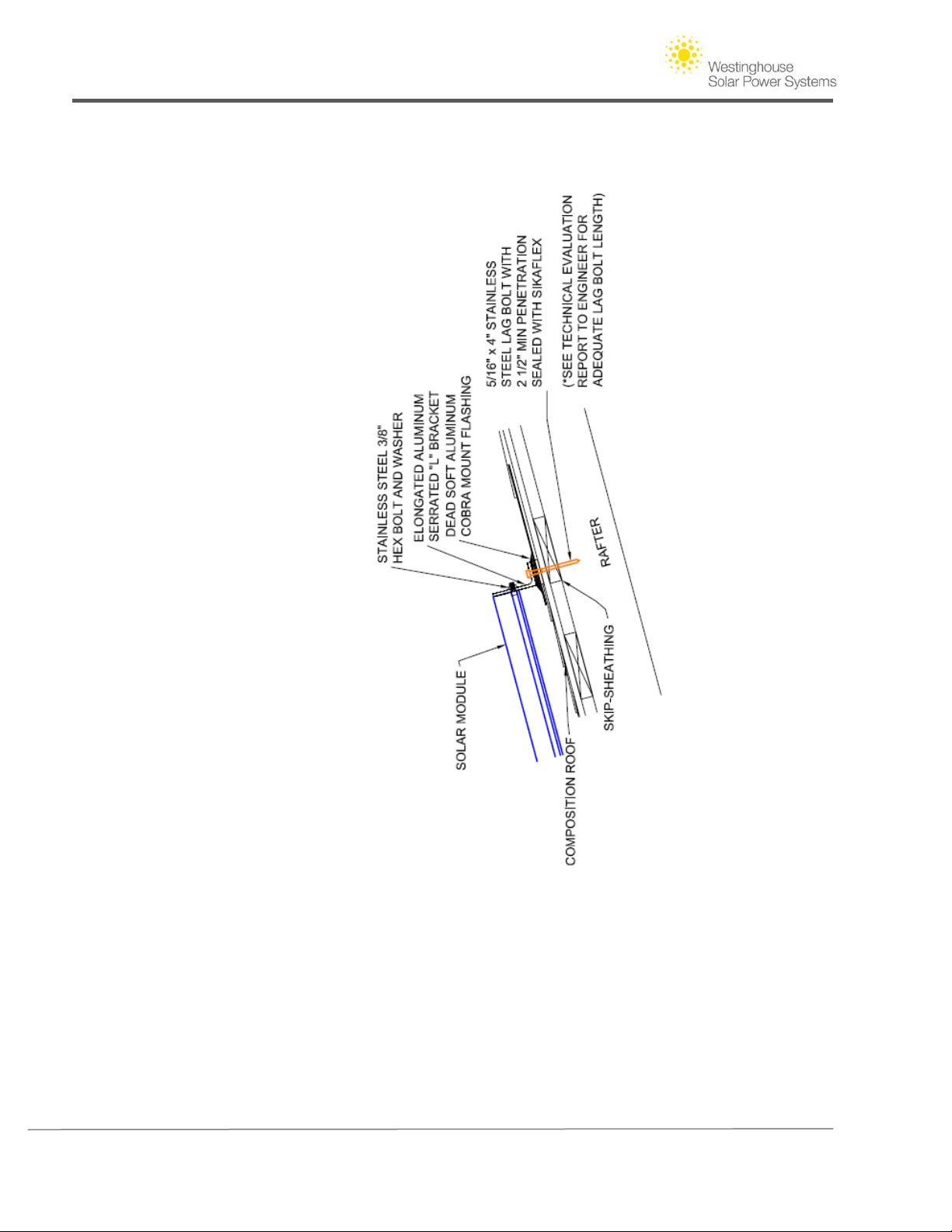
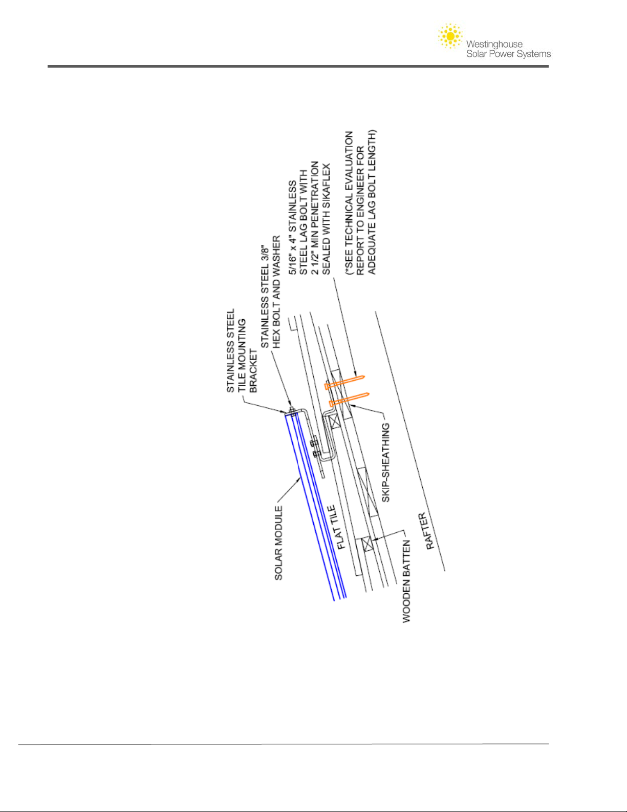
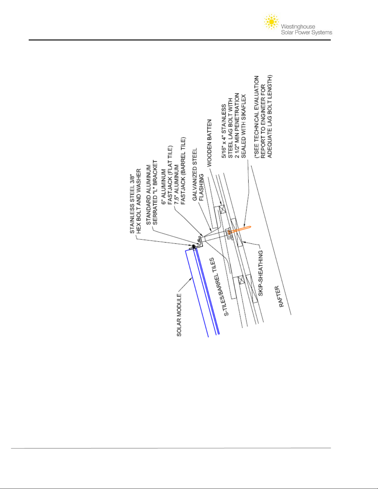
A. Roof type. The most common roof type is composition asphalt shingle. Flat Concrete tile
and barrel tile roofs are also compatible with Westinghouse Solar AC panels. This
information will determine your specific roofing kit needed. We have included roof
attachment profiles that can be included in your plans in the appendix of this guide.
B. Underlying structure. Determine the dimension of rafters and the spacing of the rafters.
For example, 2"x 8" @ 24" o.c. describes 2" by 8" rafters that are spaced 24" on center.
This information will determine where you locate your attachment points on your roof
layout. Also, planning departments typically will not ask you to draw individual rafters on
your submitted layout, but they will need this information noted on the plans to confirm the
structure meets code requirements.
C. Roof Pitch. Measure the pitch of your roof in degrees.
D. Roof measurements. Take accurate measurements that can easily be transferred onto a
sheet of graph paper or into the CAD program you are working with to design the layout.
Remember to include any obstacles that will interfere with your array design. When
measuring the peak of the roof, exclude the roof cap in your measurements because this is
an unusable area for solar attachments.
E. Azimuth. This information will help you choose the optimal solar roof surfaces, and is also
crucial to include on documentation when applying for state rebates and incentives. Ideal
orientation is south, but east and west facing roofs are OK with only a slight output penalty.
Panels are designed for flush roof mounting at your existing roof slope.
F. Shading. Using a SunEye or Solar Pathfinder device, determine shading and design a layout
that will maximize system output.
2. Drafting a Roof Layout
This portion of the process can be done using a graph paper or in a more detailed tool such as a
CAD program. Before submitting your layout to your local permitting jurisdiction, request
information from your local building permit office on special requirements for PV design in your
area. These requirements may include roof setbacks and clearances that need to be included in
your design.
Copyright © 2011 - Westinghouse Solar 7 | Page
Page 12
Westinghouse Solar AC Installation Guide
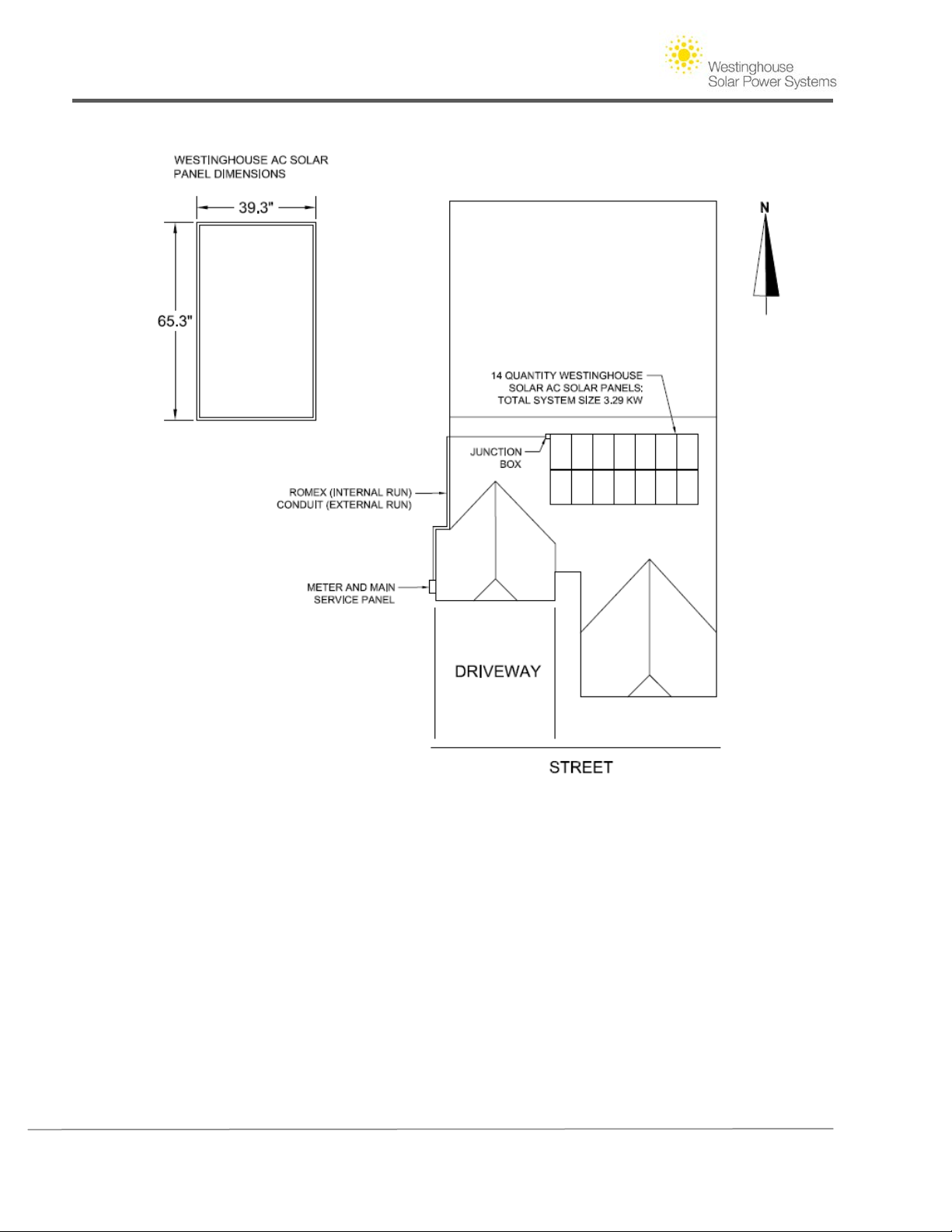
Figure 5 - Sample roof layout and panel dimensions
3. Elements of Designing a Solar System Specific to Westinghouse Solar AC Panels
Before you add the solar array to your roof layout design become familiar with the basic design
principles specific to Westinghouse Solar AC. You should understand the spacing requirements,
mounting methods, and wiring basics that are a part of the Westinghouse Solar AC design. You will
need to follow the equipment specific rules below in order to create a safe and efficient
Westinghouse Solar AC system.
-Westinghouse Solar AC Branch Circuits. -When Westinghouse Solar AC panels are arranged on
a roof layout, they are wired in parallel, and operate independently on a per panel basis. For
this reason, panels can be placed on roofs of varying pitches, orientations, and shading levels.
Copyright © 2011 - Westinghouse Solar 8 | Page
Page 13
Westinghouse Solar AC Installation Guide
Unlike with ordinary DC solar panels, the performance of Westinghouse Solar panels will not be
compromised by adjacent lower producing panels in the same branch circuit.
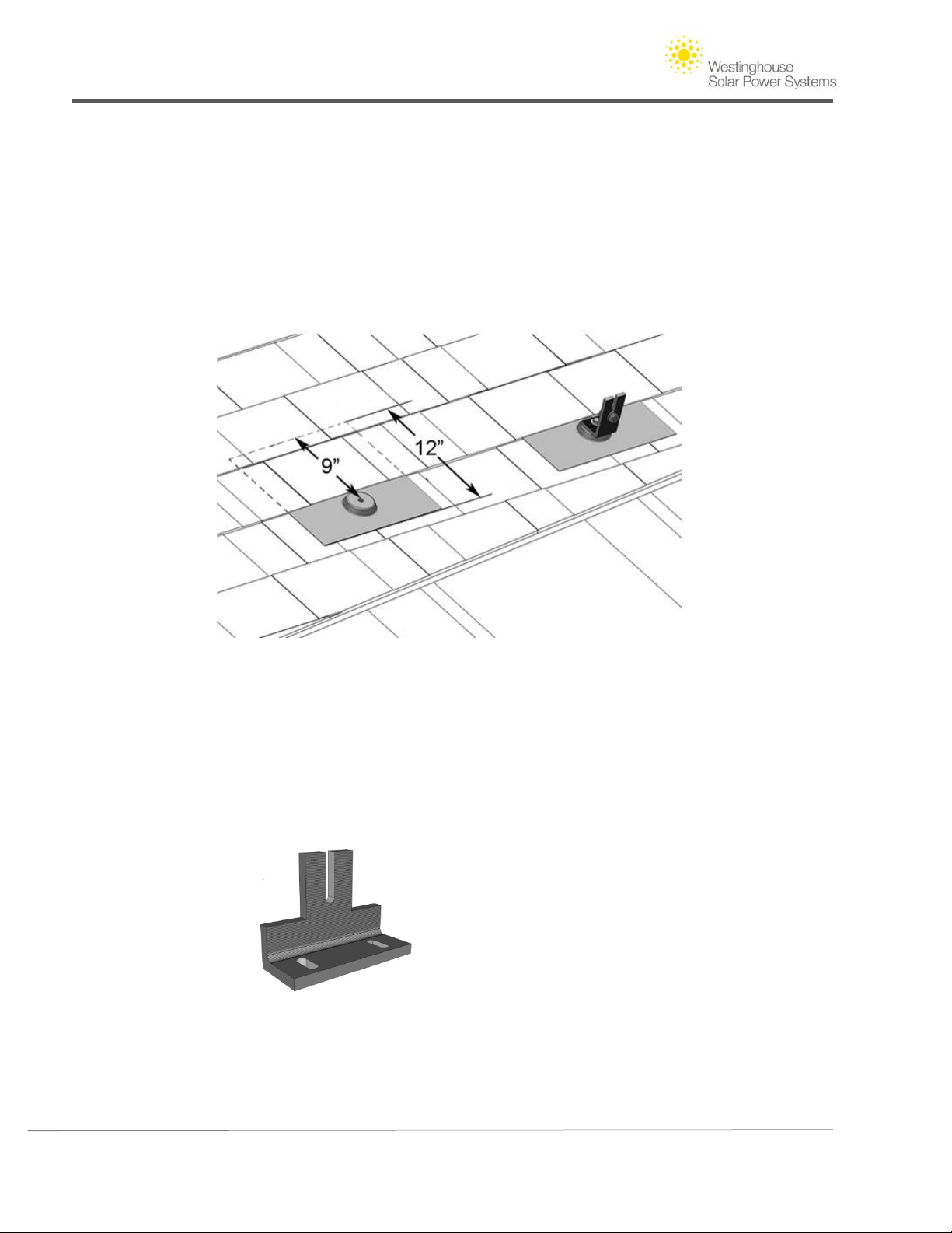
-Include Buffer Space Around the Array in your Design. Consider the necessary buffer room
needed around the array for the roof mount to be sufficiently “flashed.” To be flashed is a
roofing term for professionally sealing a penetration by installing a separate metal flashing
underneath the row of shingles above the penetration, as illustrated below. Concrete tile and
barrel tile dimensions are shown in the Appendix.
Figure 6 - Roof top buffer room example on composition shingle roof
Use an Offset L Bracket when modules connect over an attachment point. The Offset L Brackets
allow you to secure two modules together with a splice over an attachment point. Use the
Offset L Bracket instead of a regular L Bracket for an additional 2 inches of mounting flexibility.
Figure 7 - Offset L Bracket
Copyright © 2011 - Westinghouse Solar 9 | Page
Page 14
Westinghouse Solar AC Installation Guide
4. Westinghouse Solar Mounting and Structural Requirements
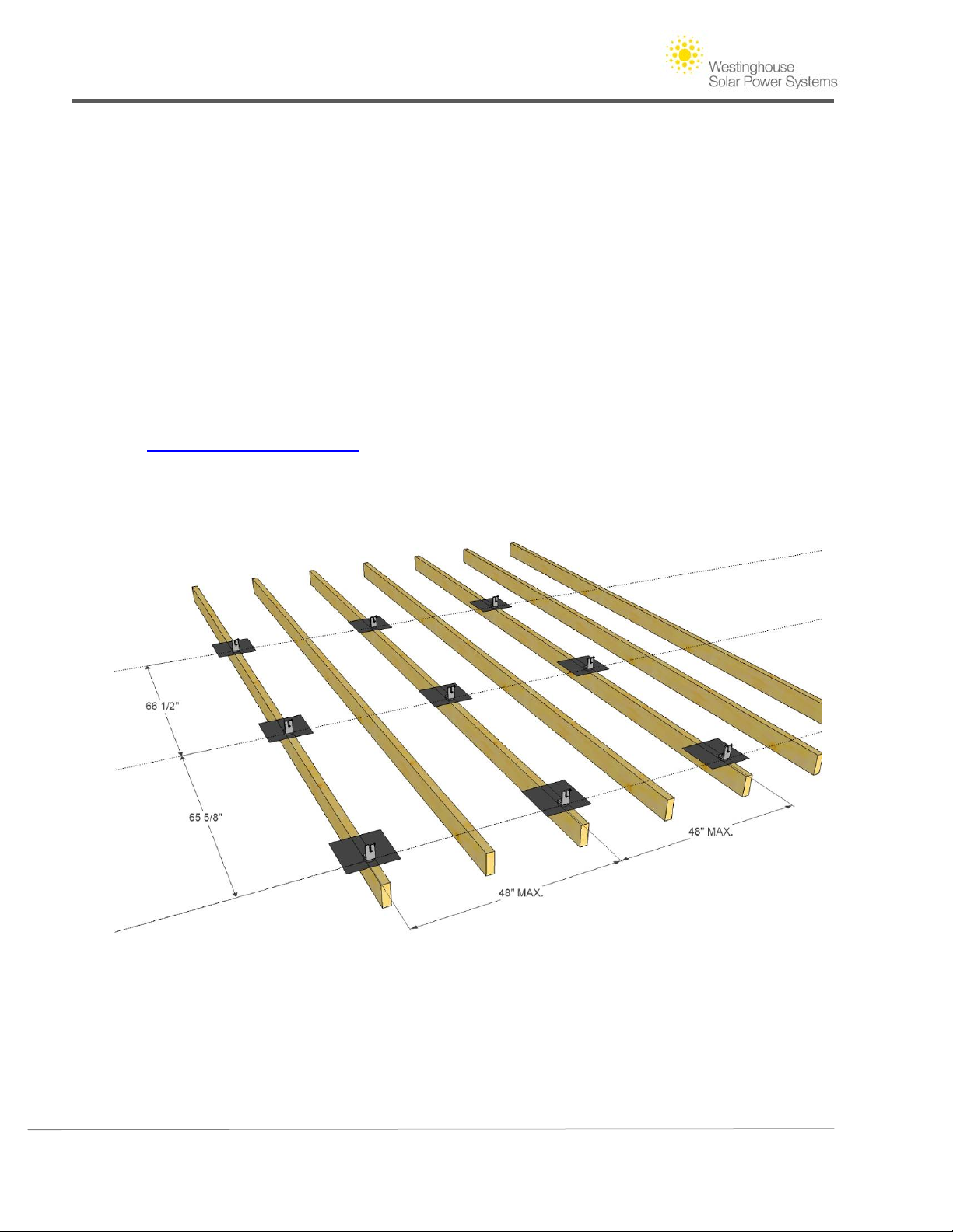
To satisfy Westinghouse Solar's minimal structural requirements there are two simple design rules
that usually dictate the minimum mounting requirements. As Westinghouse Solar AC panels are
connected together they form a rigid structure. The span of the panels between roof attachments
is generally 48”. As per the Technical Engineering Report (available on WestinghouseSolar.com,
greater spans can be used in sheltered wind condition areas, and shorter spans may be necessary
under high wind conditions. These roof attachments are located on both the top and bottom of
your single row array. The second rule requires that panels which overhang the last footing in a
row may stick out no more than a maximum of 16" from that footing. Before finalizing your roof
drawing, check with your local building department to identify any unique wind or snow load
requirements that pertain to your jurisdiction. A combination of shortening the maximum span
between roof attachments and increasing the length of your lags will enhance the wind load
rating of Westinghouse Solar AC panels. Refer to the Technical Engineering Report on
www.westinghousesolar.com to determine maximum allowable anchor spacing.
Figure 8 - Basic Westinghouse Solar attachment point layout
(Refer to Technical Engineering Report on www.westinghousesolar.com)
Copyright © 2011 - Westinghouse Solar 10 | Page
Page 15
Westinghouse Solar AC Installation Guide
Warning: The Westinghouse Solar AC Solar Panel System must be mounted over a fire
resistant roof covering rated for the application. Attachment points must be properly located
relative to the panel so the brackets do not exert lateral pressure on the frame. Care should
be taken to ensure the mounting points are positioned in accordance with the Westinghouse
Solar AC panel requirements. The measurements in the following diagrams represent distance
between lag bolt penetrations. Westinghouse Solar L-brackets feature an adjustable oblong
base slot that is adjusted to exact panel dimensions as the system is installed. Failure to
adjust the L-Brackets and associated hardware to the exact panel dimensions may cause the
hardware to exert lateral pressure on the Westinghouse Solar Frame voiding the warranty.
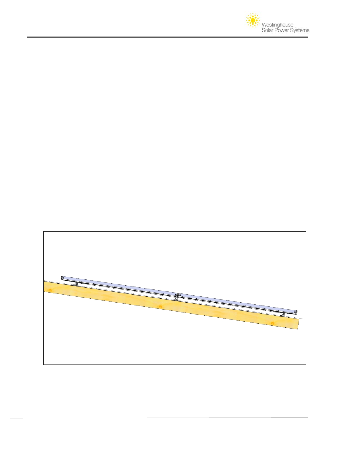
Shared Attachment Points
Westinghouse Solar roof layouts that include multiple rows of panels leverage the installation
efficiencies of panel-integrated racking. The stainless steel Westinghouse Solar splices
(Connectors) that ground and connect panels in the east-west direction serve as structural
components. The North-South Bracket serves as a structural connection and enables sharing of
footings between the first and second rows (and all consecutive rows until the top of array).
The Westinghouse Solar North-South Bracket allows the upper row to share the lower rows
upper footing. The Westinghouse Solar AC Solar Power System has been tested and certified at
an accredited laboratory as an integrated system. When designing a multiple row array with
Westinghouse Solar AC, the entire array can be seen as a unified structure, and not single rows
of panels on independent racking systems as with ordinary solar panels.
Figure 9 - Profile of roof attachments with shared center attachment point across two panel rows
Copyright © 2011 - Westinghouse Solar 11 | Page
Page 16
Westinghouse Solar AC Installation Guide
5. Drafting a Solar Array
Begin drawing Westinghouse Solar panels on the predetermined solar roofs considering the above
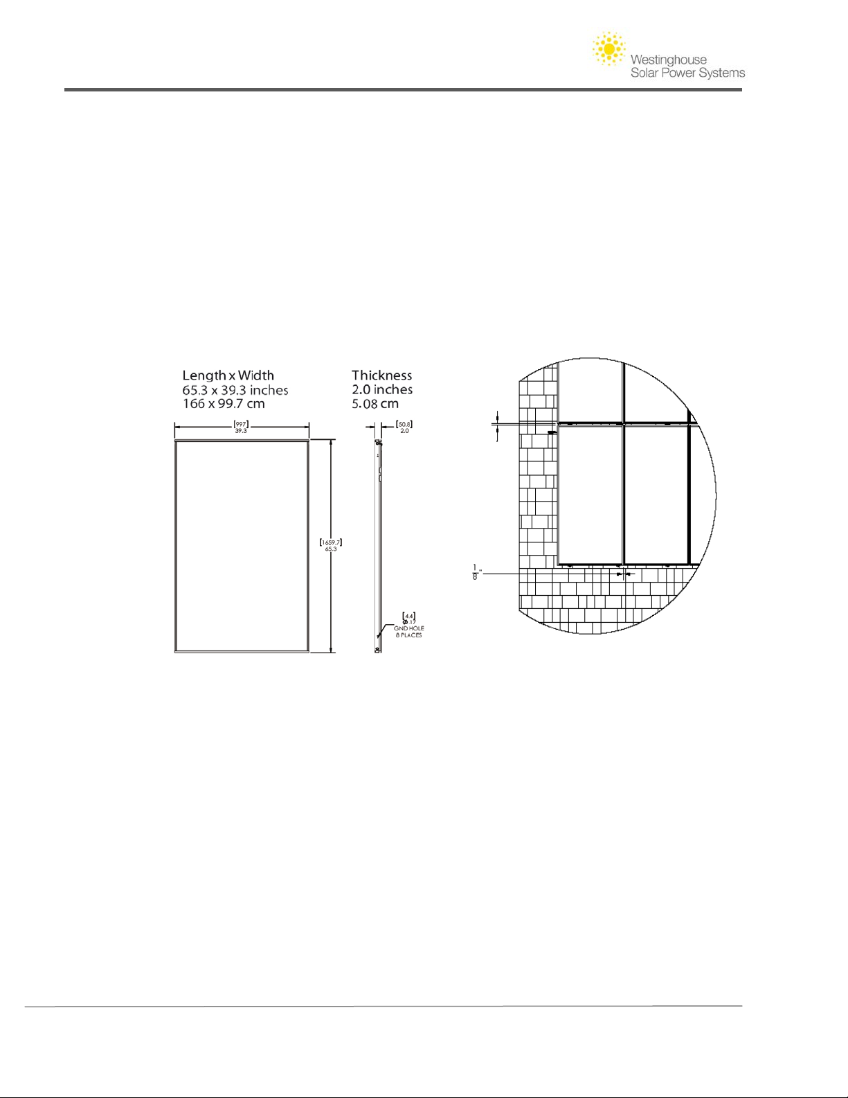
mentioned design parameters. Westinghouse Solar AC panels measure 65.3" long by 39.3” wide.
Include a 1" gap between rows in the north/ south direction to accommodate the installation of the
Westinghouse Solar North-South Bracket. To allow for thermal expansion in large arrays, include a
one inch expansion gap for every 12 Westinghouse Solar panels in a continuous row.
Take time to review how the Westinghouse Solar components you are working with are
developed and organized in the included roof layout. The default roof attachment profiles
included in the Appendices may be attached to your plans for review by local planning and
permitting jurisdictions.
1”
Figure 10 - Westinghouse Solar inter-panel spacing and panel dimensions
Adding Additional Equipment to the Roof Layout
Westinghouse Solar AC Wire Runs
After the roof layout is complete with Westinghouse Solar AC panel locations and the existing
electrical service, identify where conduit or Romex will be run to route the arrays conductors to
the associated equipment on the ground. This can be done by simply drawing a line across your
site map and labeling the material as is seen in the sample roof layout.
Conductors
Conductors will either be run as Romex internally or through an approved conduit externally. If
an external disconnect is required in your jurisdiction, include this location on the roof layout.
Label all equipment and conduit sizes on the roof layout.
Copyright © 2011 - Westinghouse Solar 12 | Page
Page 17

Westinghouse Solar AC Installation Guide
Other Electrical Equipment
Include junction boxes and disconnects on your roof layout as needed. The conduit will connect
all of this equipment in the same sequence as your electric diagram. For this reason it may be
helpful to finalize the electrical line diagram before finalizing equipment placement on the roof
layout.
Copyright © 2011 - Westinghouse Solar 13 | Page
Page 18

Westinghouse Solar AC Installation Guide
Section III. Creating an Electrical Diagram
It is important to understand the electrical design principles specific to Westinghouse Solar technology
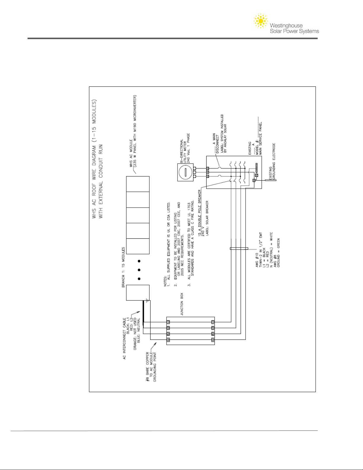
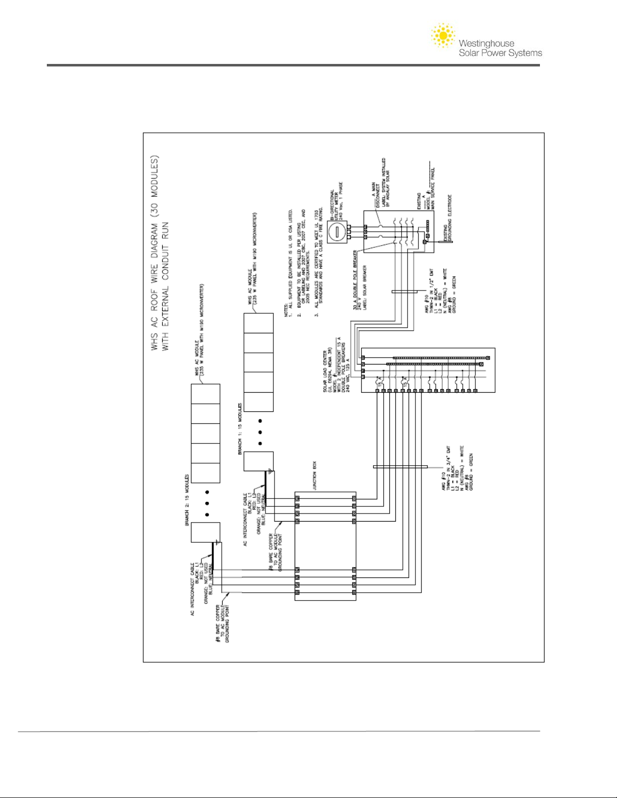
before you begin your electric line diagram. Sample designs for 15 panels (or fewer), 30 panels and 45
panels are provided in an Appendix. Below are some important concepts to consider as you create
your roof layout and electric line diagrams:
1. Westinghouse Solar AC Electrical Requirements
A. Westinghouse Solar AC Panels may be arranged in branch circuits of up to 15 when working
with 240V single phase electrical systems. Each branch circuit will need to be isolated using
NEC compliant circuit protection
B. When Westinghouse Solar AC panels are arranged on a roof layout, they are wired in parallel,
and invert DC power on a per panel basis. For this reason, panels can be placed on roofs of
varying pitches, orientations, and shading scenarios. Their performance will not be hindered
by adjacent panels in the same branch circuit.
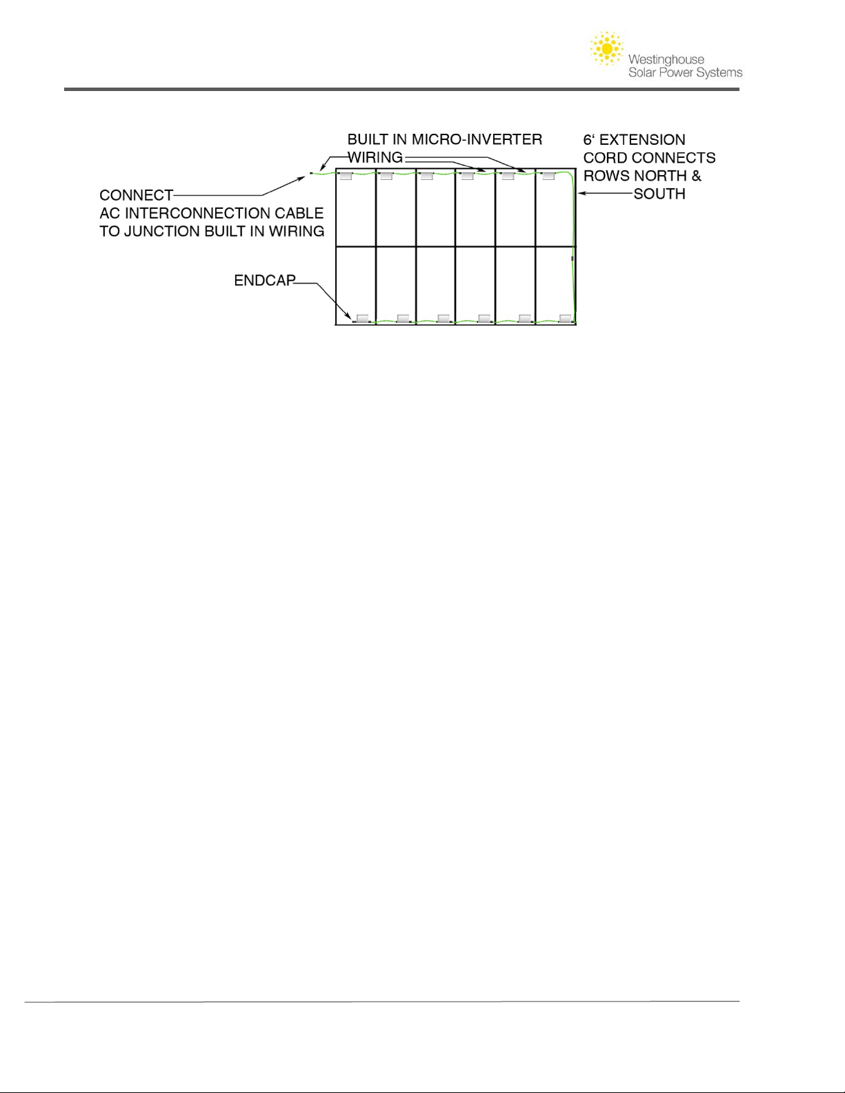
C. Westinghouse Solar AC branch circuits require three proprietary components to complete a
multi row branch circuit. An AC branch circuit is ended with an “end cap,” which is a plastic
fitting that protects the last inverter in a circuit from moisture and exterior elements. Because
the wiring harnesses come built into the inverters at a preset length, a 6' extension cable is
necessary to wire branch circuits in the north /south direction, and also to route the inverters
past obstructions (such as a vent pipe). Finally, Westinghouse Solar AC circuits are completed
with a “Pigtail” connector; the Pigtail transitions the inverter's conductors from the UV rated
insulation to four color-coded conductors that can be utilized inside a junction box on the
edge of an array. Each Westinghouse Solar AC kit includes one Pigtail and one end cap.
D. Inverters mounted on Westinghouse Solar AC panels work most conveniently when the wiring
harnesses are aimed towards the junction box, or final destination for a circuit on a rooftop.
By carefully planning the direction and orientation of Westinghouse Solar AC Panels, your wire
management will be simplified and system will be installed with fewer extra components.
E. Westinghouse Solar AC inverters are attached to the panel frame using an UL-approved
bonding method. These attachments utilize thread-forming bolts in addition to star washers
to ensure a solid and redundant bonding path between the frame and inverter.
Copyright © 2011 - Westinghouse Solar 14 | Page
Page 19
Westinghouse Solar AC Installation Guide
F. Drafting the Electrical Line Diagram.
Figure 11 - Inverter components in a two row array
2. Single line diagram preparation
Prior to drafting the diagram it is necessary to identify the size and capacity of the existing
electrical system components. You will also need to research the additional equipment you may
need to include based on special local utility and building department requirements.
Electrical Site Survey List:
A. Main Panel bus rating- This information can be found inside the electrical service door
on a sticker label, common residential bus ratings are 100A, 125A, and 200A.
B. Main Disconnect Rating- The main disconnect rating is printed directly on the main
breaker. It is common for the main breaker's rating to match that of the main panel
bus. The main breaker should not exceed the rating of the main panel.
C. Available breaker space- The most straightforward method to back feed a residential
grid-tied electrical service is by utilizing a double pole breaker to interconnect your
circuit (up to 15 panels) or circuits (if more than 15 panels) to the main panel. Survey
how many breaker spaces are available; a double pole breaker will require approx. two
inches of space in your average residential service panel.
D. Grounding- Check that a ground rod is present, serving as a grounding electrode to the
main electrical service. If you cannot identify a grounding electrode, per section 250 of
the NEC, a new one will need to be installed to assure a safe grounding path for your
solar equipment. The grounding electrode, new or existing needs to be included in your
electrical line Diagram.
E. Wiring Location- Is there a clear pathway through crawl spaces and attics to route your
Westinghouse Solar AC system conductors? Will the wire run be external to the
structure? How long is the wire run? This information will be a factor in sizing your
Copyright © 2011 - Westinghouse Solar 15 | Page
Page 20

Westinghouse Solar AC Installation Guide
conductors and what types of materials you will need to use in reference to the U.S.
NEC, if applicable.
3. Electrical Line Diagram
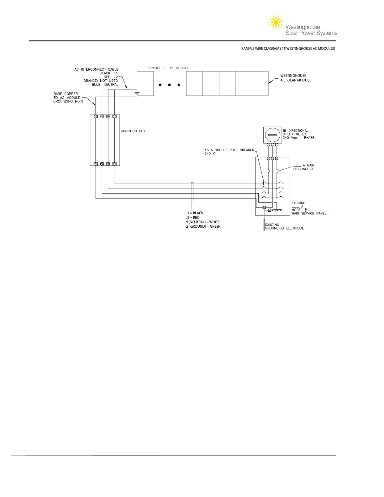
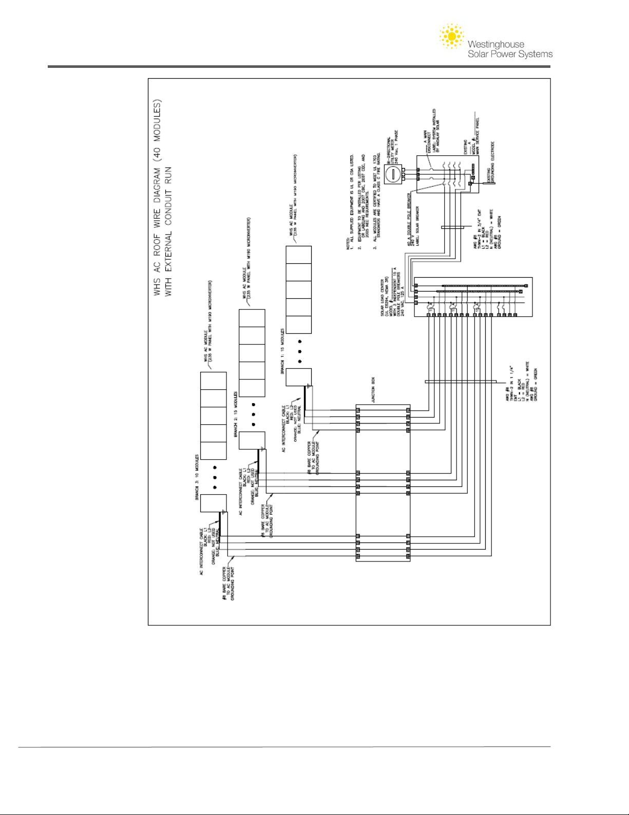
The sample Electrical Line Drawings in the appendix are provided as a starting point. Three
drawings (15 panels, 30 panels and 40 panels) are provided that include multiples of 15
Westinghouse Solar AC Panels in branch circuits. Use the sample drawings as a template, and
identify the exact number of panels in your system. Completing your electrical line diagram circuit
can be as simple as labeling the equipment rating and defining whether you are wiring the system
with Romex or using a conduit with individual conductors. The following details should be
provided:
• Type of utility meter, voltage rating, and phase (bi-directional utility meter, 240
VAC, 1 Phase).
• Main panel manufacturer, main panel bus rating, main disconnect rating (Square D,
200 A rated main panel, 200 A main disconnect).
• The grounding electrode and an appropriately sized conductor grounding the main
panel.
• The voltage, number of poles, and circuit protection rating of the breaker used to
interconnect with the main service, (240 V, double pole, 30 amp breaker).
Conductor sizing, overcurrent protection, load centers, disconnect switches, and other equipment
must be sized according to the National Electrical Code, in addition to any special requirements of
the local permit jurisdiction. Special considerations for solar include, but are not limited to, the
following:
• Conductors and connectors used on the roof must be rated for 90 degrees C
• Conductors on the roof should have their ampacity de-rated for a temperature of at
least 70 degrees C.
• Voltage drop between the array and the main panel should not exceed 1.5%.
• The sum of the overcurrent protection of all power sources (line + PV) feeding a bus
bar or conductor must not exceed 120% of the current rating of that equipment.
• Warning labels as required by your local jurisdiction.
4. Grounding
Rows of Westinghouse Solar AC panels spliced in the East-West direction are bonded by the same
stainless steel splices that connect the panels structurally. The North-South bracket provides
grounding when used with grounding washers for columns of Westinghouse Solar panels.
Westinghouse Solar splices are a UL listed grounding component. At the end of each row in the
east-west orientation there is a factory designated bonding location for attaching a lug.
Copyright © 2011 - Westinghouse Solar 16 | Page
Page 21
Westinghouse Solar AC Installation Guide
Figure 12 - Single Branch Circuit Westinghouse Solar AC Wire Diagram
Copyright © 2011 - Westinghouse Solar 17 | Page
Page 22

Westinghouse Solar AC Installation Guide
Section IV. Installation
1. Safety Warnings
• Before installing the Westinghouse Solar AC Panel, read all instructions and cautionary markings
in the Westinghouse Solar AC documentation
• Perform all electrical installations in accordance with all local electrical codes, the National
Electrical Code (NEC), ANSI/NFPA 70 and local utility requirements.
• Be aware that installation of this equipment includes risk of electric shock. Normally grounded
conductors may be ungrounded and energized when a ground fault is indicated.
• Do not wear metallic jewelry, which may become a cause of electric shock during installation.
• Do not expose solar panel to sunlight concentrated with mirrors, lenses or similar means.
• Do not walk on or drop tools or hard objects on the glass of the solar panel.
• Do not scratch the back sheet (behind the glass) of the solar panel.
• Use approved glass cleaning products on panels
• Do not connect the panels directly to power loads such as a motor since the variation of output
power depends on solar irradiation which may cause damage to the connected load.
• Do not block frame drain holes.
2. Layout
Laying out an Array
Following the roof layout created by the engineer of record, use the provided dimensions to
draw out the corners of a solar array. Adjust your array in the east/ west direction so that the
edge of the solar module frame starts within 16" of the closest rafter to the interior of the array.
Westinghouse Solar AC modules may not overhang the last array attachment point by more
than 16" or 40% of the module’s width. Remember to include 7/8" of space between modules
in the north-south direction. This gap accommodates the serrated L along with the
Westinghouse Solar North-South Bracket.
Copyright © 2011 - Westinghouse Solar 18 | Page
Page 23
Westinghouse Solar AC Installation Guide
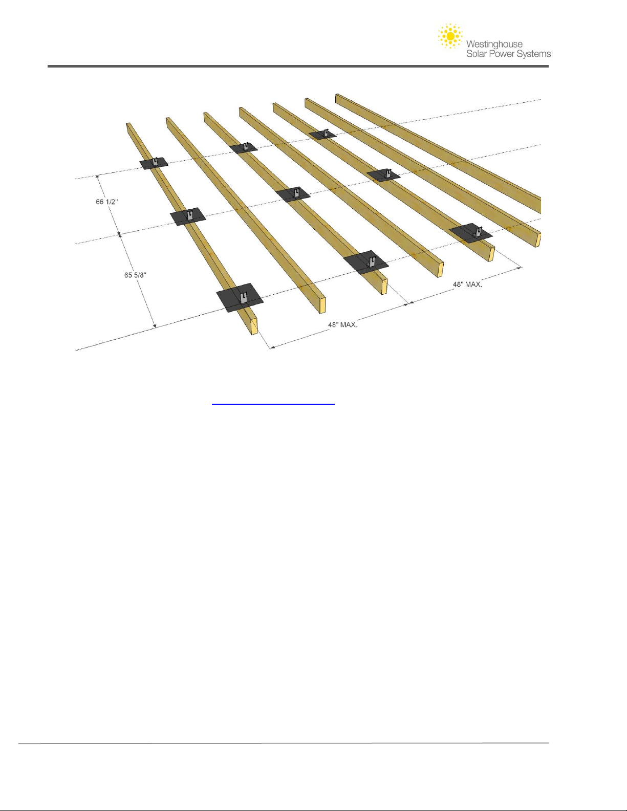
Figure 13 – Laying out attachment points for Westingh ous e Solar M odule s
(See Engineering Supplement on
www.WestinghouseSolar.com for required spacing)
Multiple Module Rows
After defining the corners of the array on the roof using chalk or a wax crayon, snap chalk lines
representing rows of attachment points required for your array. In the following sample array
there are three rows of attachment points to accommodate two rows of Westinghouse Solar
modules. The first row of attachment points starts at the bottom horizontal perimeter of the
Array. Snap a chalk line across the bottom two corners of the array to define the first row of
attachment points. The second row of attachment points is created by measuring 65-5/8" up
the pitch of the roof from the first chalk line; snap a second line at this interval. The spacing
interval for the next row of attachment points up the pitch of the roof is 66-1/2". This larger
distance represents the necessary three quarter inch gap between all rows in the north/ south
direction. If a third row of modules were to be installed there would also be 66-1/2" space
between the third and fourth row of attachment points. Note that all L-Brackets are oriented in
the same direction; this allows access to secure the Lag bolts once modules are put in place. The
measurements in the Figure above represents distance between lag bolt penetrations;
Westinghouse Solar L-brackets feature an adjustable oblong base slot that is adjusted to exact
module dimensions as the system is installed.
Copyright © 2011 - Westinghouse Solar 19 | Page
Page 24
Westinghouse Solar AC Installation Guide
Marking Attachment Points
Using the chalk lines snapped create marks on the roof surface where these horizontal chalk
lines intercept the rafters. Attachment points are located at this junction. If your rafter
locations are unknown, follow the rafter locating tips below. The illustration above shows
attachment points spaced at 48" on center in the east-west direction. Carefully review the
engineering set of plans provided, attachment points may be spaced at longer and shorter spans
depending on wind conditions.
Tips for finding rafters on a composition shingle roof
A. Look for exposed rafters under the eaves of the building. Mark these locations with chalk at
the gutter for reference on the roof.
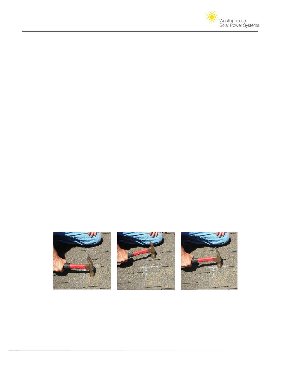
B. Tap hammer repetitively, gently moving from left to right across the assumed rafter location.
You should be able to detect the firmest spot by paying attention to the sound and bounce of
the roof surface. The more the hammer bounces the further your hammer is from the rafter
location. Mark the firmest location with piece of chalk prior to pre-drilling. This technique also
works on concrete tile roofs when a tile is removed exposing the roof sheeting.
C. If there is attic access, identify where rafters are located in proximity to roof vents, roof hips,
or other objects visible from above and below the roof surface. Rafter spacing may be
inconsistent, creating a map of specific rafter spacing that is visible from the attic will help
installers on the roof.
D. When probing for the first rafter location, use a pry bar to loosen the composition shingle.
By bending back the course of shingles where you are penetrating, you will be able to easily seal
and cover any misses.
Figure 14 - Tapping across assumed rafter location to find firmest point
Copyright © 2011 - Westinghouse Solar 20 | Page
Page 25
Westinghouse Solar AC Installation Guide
3. Mounting
The examples that follow illustrate how to install Westinghouse Solar Power Systems mounting
components on composition a shingle roof.
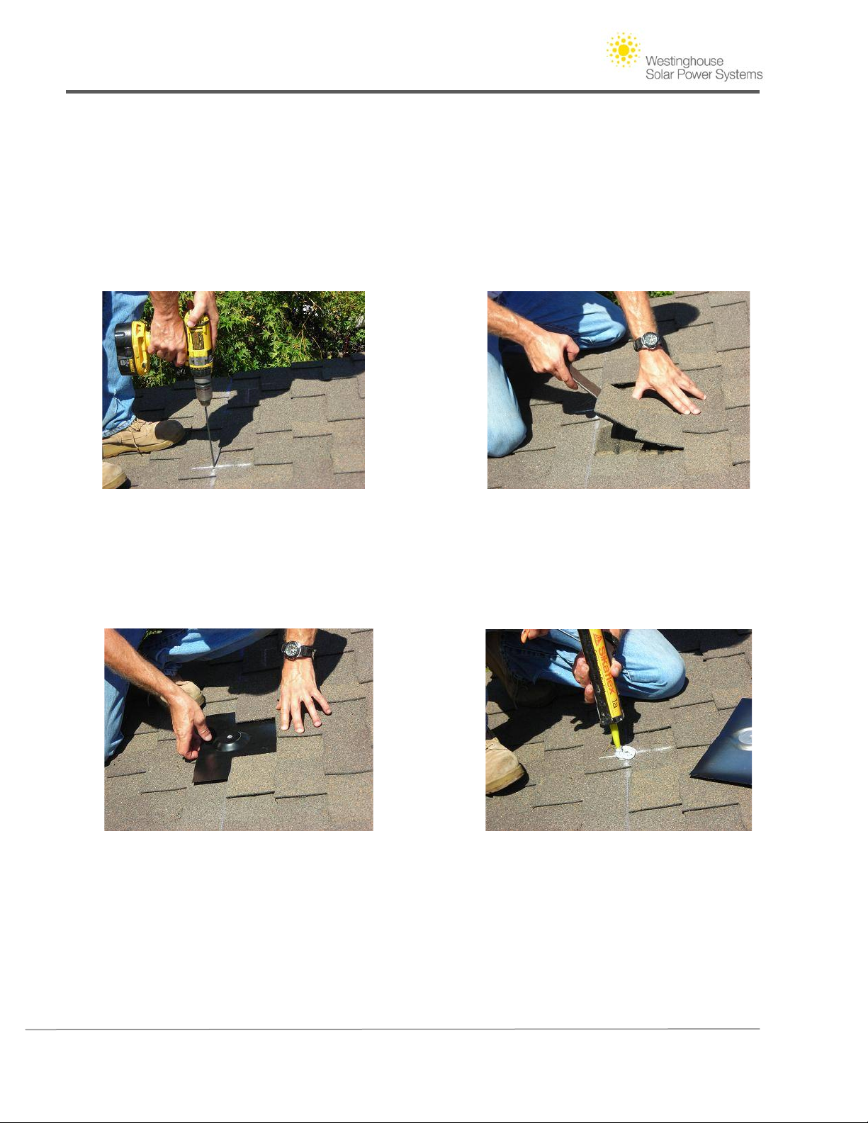
Step 1A. Pre-drill at the pre-determined roof penetration chalk markings established in step 2 of
this section. The drill bit is held perpendicularly to the roof surface, this will ensure maximum
strength at the attachment point by securing through the most solid point of the underlying rafter.
The roof attachment points will require a minimum of 2-1/2" of rafter penetration.
Step 1B. Loosen the composition shingles directly above the pre-drilled roof penetration, make
sure to loosen and remove any nails or staples that will interfere with the Composition mount
flashing. The Composition mount flashing will extend 9" above the pre-drilled hole. Test that the
shingles are adequately loosened by "dry fitting" the comp mount flashing. Line up the hole in the
flashing with the pre-drilled hole in the roof.
Step 1C. Apply Roofing sealant. Using a caulk gun, backfill the roof penetration and apply a
liberal amount of sealant to the immediate area. Apply a circle of sealant to the puck on the
unfinished side of the Composition mount flashing. Finally, applying a horse shoe shape of sealant
above the puck will act as redundant protection if roof conditions up the slope are compromised.
Copyright © 2011 - Westinghouse Solar 21 | Page
Page 26
Westinghouse Solar AC Installation Guide
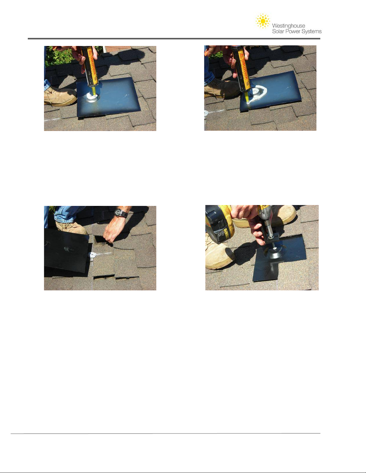
Step 1D. Installing Hardware - Place the Composition mount flashing in its final location prior to
installing the lag bolt. Holding the lag bolt and fender washer, thread this hardware through the
oblong hole at the base of the serrated L-Bracket. With all of these components assembled, place
the tip of the lag bolt through the 5/16" hole in the raised area of the Composition mount flashing.
Before tightening, the lag bolt must be seated in the pre-drilled hole; this will ensure that the lag
bolt does not damage the underlying rafter, achieving maximum attachment strength.
Step 1E. Tightening Lag Bolts-Using socket wrench or impact driver with a 1/2" socket, slowly
torque down lag bolts until the head of the lag bolt is 1/8" from seating on the Fender washer.
This 1/8" of space will allow the installer to line up and adjust the L brackets before tightening
them down to their final position. Excess caulk should squeeze out of the hole and surround the
head of the lag bolt.
Copyright © 2011 - Westinghouse Solar 22 | Page
Page 27
Westinghouse Solar AC Installation Guide
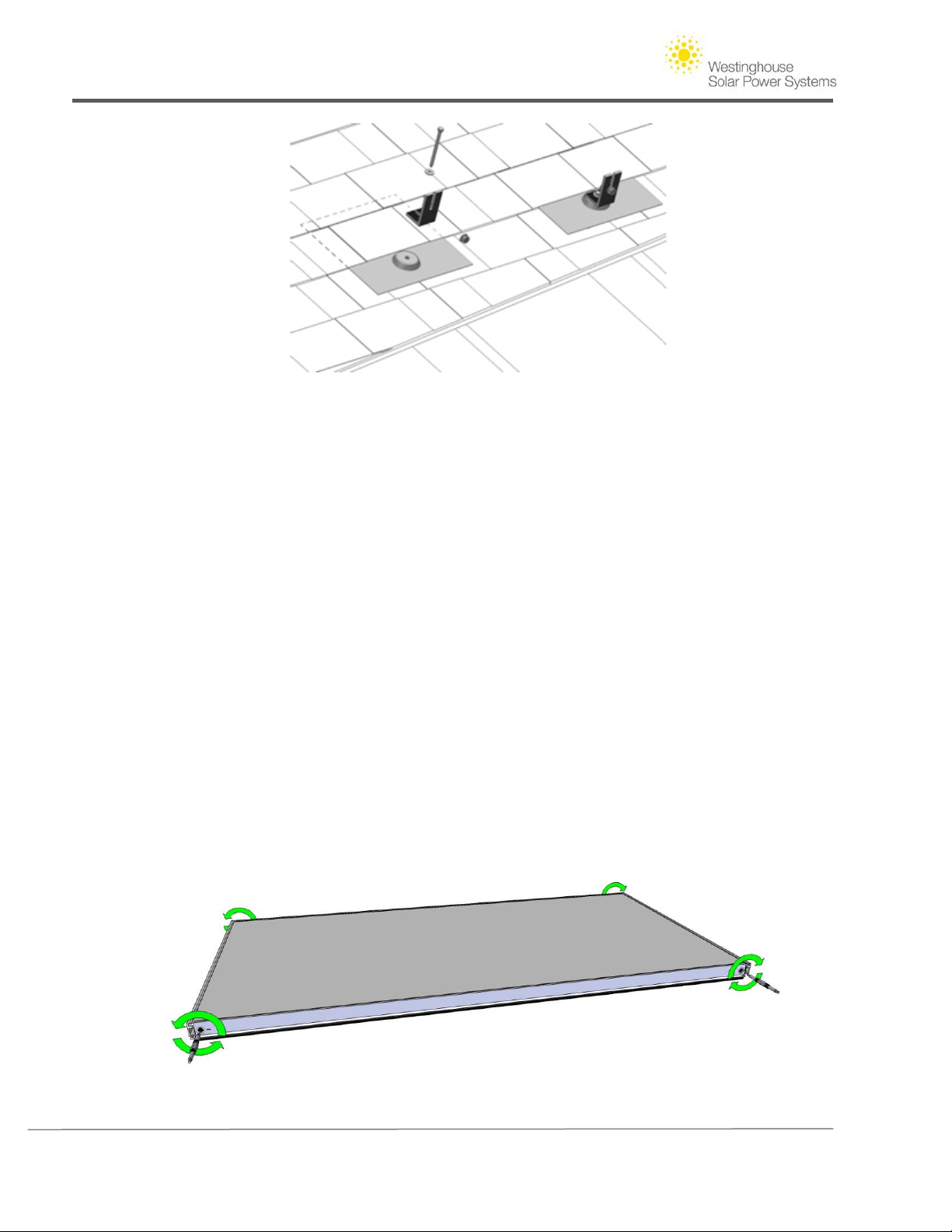
Figure 15 - Detail of Composition mount components pre and post installation
Step 1F. Finalizing the First Row of Attachments - Following the installation the first row of
attachments, tighten the lag bolts furthest to the East and West, The Lag Bolt must be centered
within the L Brackets oblong hole to ensure good fit for rows of modules up the roofs slope.
Once the two end attachments are tight, the L brackets between them are tightened to 15-20 ft.
/lbs. Use a string pulled taught from end to end to align all the interior brackets in a straight
line. The L brackets in the second row up the slope of the roof remain loose until the first of
modules are installed. Leaving the upper L-brackets loose allows the module frames to be
installed without interference.
4. Module Installation
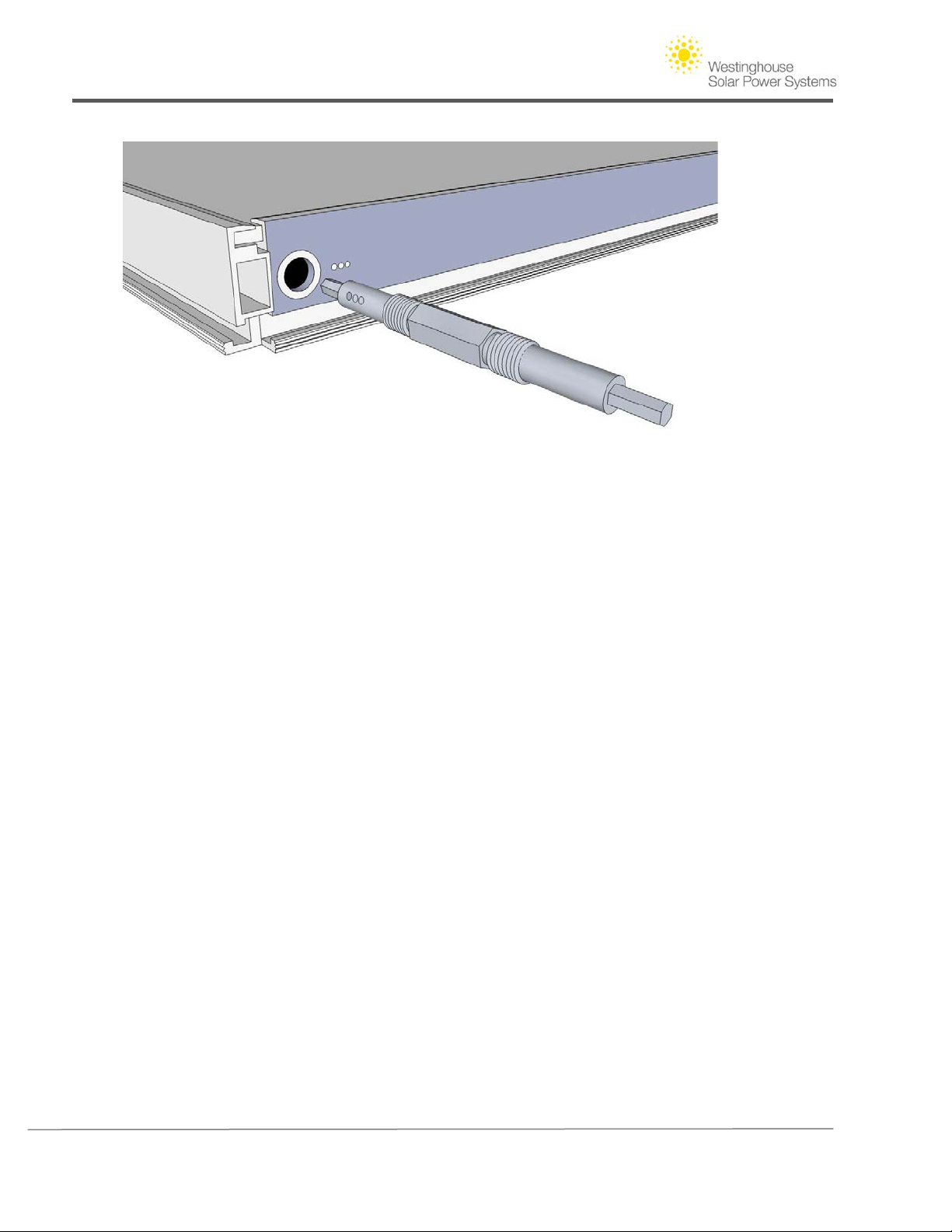
The figure below illustrates the thread patterns of a Westinghouse Solar Splice. Notice that the
threads on either end are opposite. This design feature allows the splice to connect two
Westinghouse Solar module frames together when rotated. Observe that one end of the splice
is marked with three small circles. This marking identifies a left hand thread at that end of the
splice. Use this marking to quickly identify which end of the Westinghouse Solar splice you are
holding. Splice Channels are either marked with three small circles to identify a left hand thread
fit or are blank to identify a right hand thread pattern. If a splice does not thread with ease, try
the other end, do not force the Westinghouse Solar splice.
Figure 16 - Westinghouse Solar Splice thread direction
(Tightening)
Copyright © 2011 - Westinghouse Solar 23 | Page
Page 28
Westinghouse Solar AC Installation Guide
Figure 17 - Westinghouse Solar Splice thread direction
(Tightening Westinghouse Solar Splice and frame left hand thread marking pattern
Westinghouse Solar Module Torque Specifications
Westinghouse Solar Splices require 5-7 ft/ lbs of torque to fully engage in the east/ west
direction. As an approximation, once you feel the Westinghouse Solar splice fully seated, turn
the Westinghouse Solar wrench 1/8 of a turn, this will create the appropriate amount of torque
for the connection of modules in the east/ west direction.
Installing the First Row
Prepare the module by inserting 3/8" hex bolts into the top and bottom Groove of the module
frame. Position the first module above the first and second row of L Brackets using two people
to carefully lower the module into place. 3/8" hex bolts are adjusted inside the Groove to line
up with the L Bracket fork. 3/8" Flange Nuts are threaded onto the 3/8" hex bolts loosely, to
allow height adjustment and array leveling. The module will temporarily rest on with the 3/8"
hardware left loose. Prepare for the installation of a second module by threading two splices
into the splice channels at both the top and bottom of the frames longer edge. The splices are
used to interconnect the neighboring modules in the east/ west direction. When tightened
simultaneously, the two splices will draw two modules together. Leave the inverter wiring
harness on the roof surface where it will be accessible after a second module is installed.
Copyright © 2011 - Westinghouse Solar 24 | Page
Page 29
Westinghouse Solar AC Installation Guide
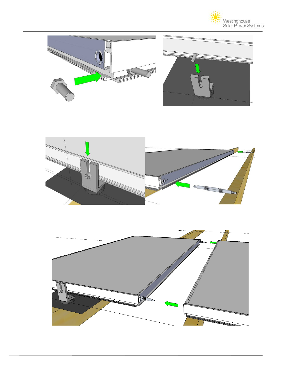
Step 1 - Westinghouse Solar module lowered on to L bracket using 3/8" hex bolts as a resting point. Repeat this step
at both the upper and lower short edges of the module.
Step 2 - Loosely thread 3/8" Flange nut onto Hex bolt, prepare for second module by inserting upper
and lower Westinghouse Solar Splices.
Step 3 - Slide the second module over the Splices installed in Step 2 until bottomed out on the splice
channel.
Copyright © 2011 - Westinghouse Solar 25 | Page
Page 30
Westinghouse Solar AC Installation Guide
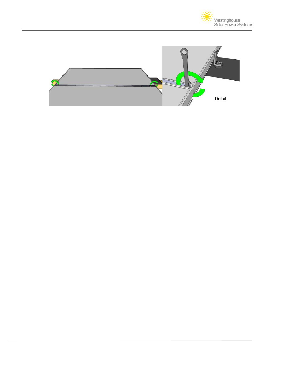
Step 4 - Rotate Westinghouse Solar splices within the frame to draw two modules together. This can be
done using the V2 wrench or with the V2 hex splice driver and a 1/4" drive ratchet. Green arrows
indicate splice rotation. Tip: Apply light pressure pushing the two modules together to ensure the
splice threads engage on the first turn.
5. Connecting Westinghouse Solar AC Wiring Harnesses
Begin to connect the built in wiring harnesses from inverter to inverter while additional modules
are lowered into place. V2 modules require the wiring harnesses to be connected before adjacent
modules are spliced together. The wiring harness and bulkhead connections are oppositely sexed,
so that multiple inverters can be connected to form one continuous AC branch circuit. Wire
connectors are keyed and slotted and will not fully engage unless the keyed connector is correctly
rotated to match the male and female connector patterns. Once the first row of Westinghouse
Solar V2 modules is complete secure the wiring harnesses to the module frame by preloading the
wire management clip with the AC wiring then clipping the plastic wire management clip to the
modules C- Channel.
Completing a single row of Modules
Repeating Steps 1-4, continue to loosely assemble the 3/8" hex bolts with their associated 3/8"
Flange Nuts in the Groove of the module. Once all modules in a single row have been connected
using Westinghouse Solar splices in the east-west direction the installer can flush up and secure the
upper row of L Brackets. Torque down the lag bolts while L Brackets are flush against the module
frame, following this step the array will be resting on the 3/8" hex bolts.
If the roof surface has any undulations, causing the array to appear warped, corrective adjustment
is done at this time. A brightly colored string pulled taught across the entire array creates a straight
line reference for array leveling. Using assistance, adjust the height of the 3/8" hex bolt within the
L Bracket until the module surface is flush with the leveling string. Finalize module position by
Copyright © 2011 - Westinghouse Solar 26 | Page
Page 31
Westinghouse Solar AC Installation Guide
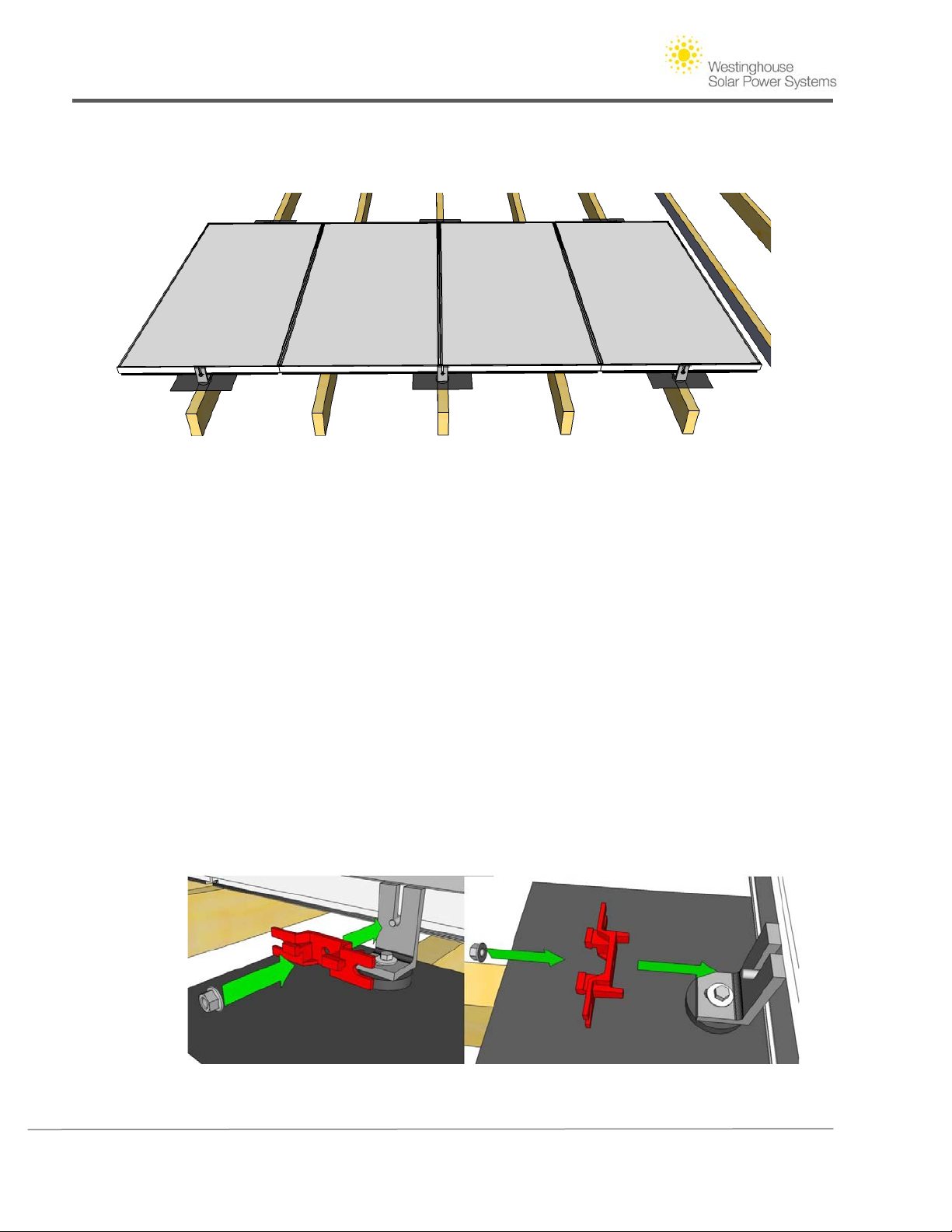
tightening down the 3/8" Flange nut against the L Bracket Once the array has been leveled, double
check all flange nuts and lags are properly secured.
Figure 18 - Single row of Westinghouse Solar modules installed
Considerations for Wiring Westinghouse Solar AC Arrays with multiple rows
If your array is continuing to an upper row, prepare the last wiring harness connector in the first
row with an Extension Cable that will reach the upper row modules bulkhead connection.
Westinghouse Solar AC Extension Cables are available in a length of 6', 12' and 20'.
Tip: Careful planning of wiring layouts will create a quick installation without interruptions or the
need to purchase additional equipment.
Installing a Second Row of Modules
To install a second row of modules in the north-south direction, Westinghouse Solar North-South
Brackets are used as a structural component to connect module frames in adjacent rows. NorthSouth Brackets balance the load of both rows on a shared attachment point in the center of the
array.
Copyright © 2011 - Westinghouse Solar 27 | Page
Page 32
Westinghouse Solar AC Installation Guide
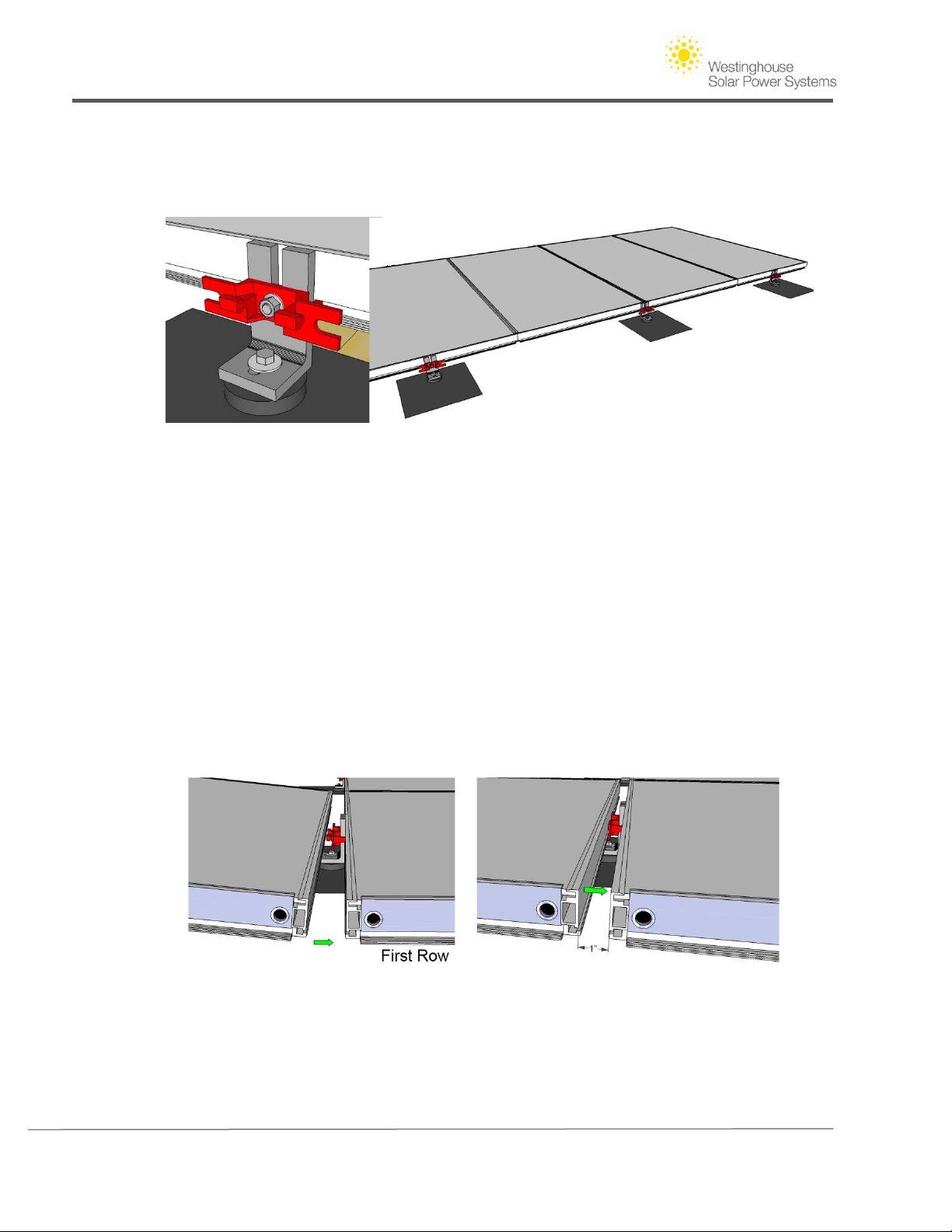
Step 5 - Assemble the north/ South Bracket to the second row of L brackets using the 3/8"
hardware. The feeler prongs are inserted into the lower modules Groove to properly align the
bracket.
Step 6 - North-South brackets are secured to the L Bracket at the top of the lower row using 3/8"
Flange nuts. North/ South Brackets are installed at all inter row L Bracket locations in preparation
for the second row of modules.
Tip: If a module is left out of the array to make room for a roof vent, an additional North /South
bracket may be required to support the second row and maintain Westinghouse Solar structural
requirements.
Step 7 - Lower the first module of the upper row into place until the module surface is level with
the lower row. Rest the module on the two North/ South Bracket fingers to hold the module in
place while 3/8" hardware is installed in the modules Groove closest to the roofs peak.
Copyright © 2011 - Westinghouse Solar 28 | Page
Page 33
Westinghouse Solar AC Installation Guide
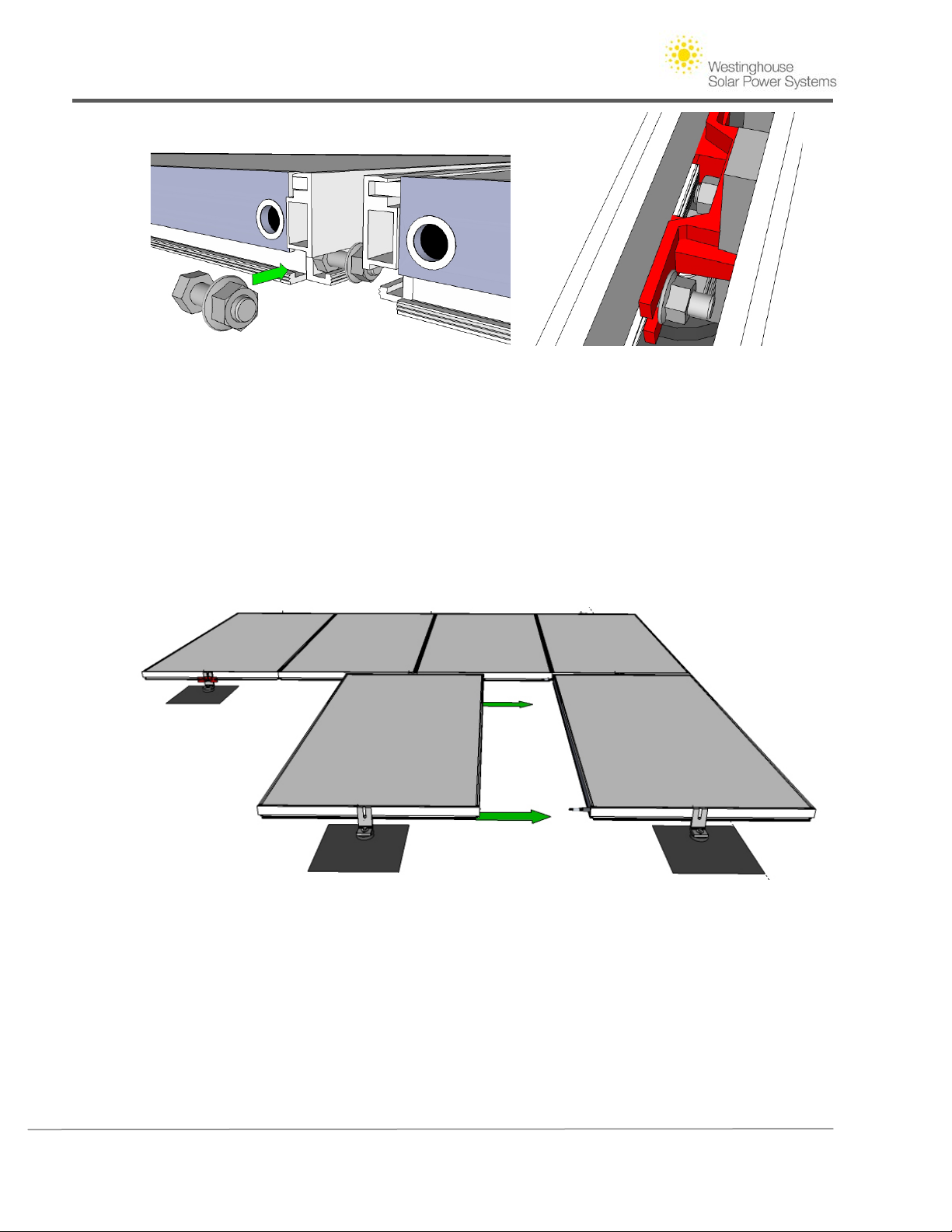
Step 8 - Slide 3/8" Hardware into the lower Groove of the second row module. Slide the hardware
through the Groove into the open end of the North/ South Bracket. Secure this hardware with the
V2 Westinghouse Solar wrench once the outer edges of the two rows are flush. By tightening this
hardware in this step you will avoid the module sliding out of alignment when the next module is
spliced in the east/ west direction.
Tip: By pre-threading the 3/8" flange nut onto the 1" hex bolt it will take fewer wrench rotations
to complete the assembly in step 8.
Step 9 - Connect Modules in the east/ west direction only after securing the North/ South Bracket
hardware and installing the 3/8" hardware at the top of the array. After each additional modules
North/ South bracket and hardware are secure follow the East/ West assembly process described in
steps 1-4.
6. Grounding
Splices and North/South brackets provide contiguous grounding between panels and across rows.
Proper grounding is achieved by assembling the module frame(s) contiguously using two bonding
Copyright © 2011 - Westinghouse Solar 29 | Page
Page 34
Westinghouse Solar AC Installation Guide
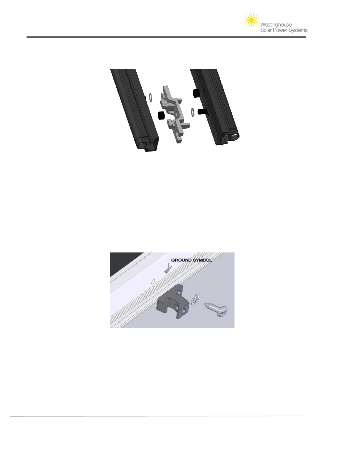
splices in the east-west direction and contiguously with the north-south direction using grounding
washers on specific North/South Brackets such that each module is electrically grounded one in a
continuous path to the grounding electrode for the array.
Figure 19 - Ground washers on the North/South Bracket ensure ground continuity across rows
Each contiguous array of module frames is then attached to the grounding electrode, in accordance
with Section 690 of the National Electrical Code (NEC) using one method as follows. Ensure positive
electrical contact through the anodizing on the module's frame by attaching the grounding
conductor to one of the 0.173” diameter (4.4 mm) holes on the frame marked ‘ground’ using an a
ILSCO GBL-4DB lug, star-washer and thread-rolling 10-32 X ½” Taptite II stainless steel screw and
torque to a value of 20 Lbf-inch. Attach a solid copper (gauge AWG 4-12) to the lug to enable array
grounding.
Figure 20 - Ground conductor applied to enable array grounding
7. Adding AC Interconnect Parts
The Interconnection cable is connected to the last inverter in a Branch Circuit. Branch circuits
must never exceed a total quantity of 15 inverters at 240VAC. Wiring patterns and direction are
planned out before the array is installed so that the final destination of the built-in wire harness
and AC interconnection cable is in proximity to the junction box. The junction box is the location
where conductors from the array transition to conductors that will run down to the main
Copyright © 2011 - Westinghouse Solar 30 | Page
Page 35

Westinghouse Solar AC Installation Guide
electrical service. The unused bulkhead connector at the other end of the circuit is sealed with
the End Cap. If your array consists of multiple rows, additional wiring components may be
necessary. If continuing a branch circuit into an upper row, the AC interconnection cable is left
out until the end of the branch circuit.
Westinghouse Solar AC Panel to Junction Box wiring – On the end of a row of panels, attach a
grounding lug to the frame at one of the designated grounding attachment points of one panel
using the thread forming grounding screw. Then, connect the grounding lug to the appropriately
sized grounding conductor inside the Westinghouse Solar Junction Box.
8. Commissioning Westinghouse Solar AC Systems
Step 1 - Install the AC Branch Circuit Junction Box
Use electrical system components approved for wet locations only. Connect the open wire end
of the AC Interconnection Cable into the junction box using an appropriate gland or strain relief
fitting. Do not connect the connector end to the Westinghouse Solar AC panels at this time, as
this is to be done during the commissioning step.
Step 2 – Verify the connections of the Inverter Wiring Harnesses
Each inverter comes with one 4-pin bulkhead receptacle and one 70-inch AC wire harness with
multi-pin connectors. The AC connectors are oppositely sexed, so that multiple inverters can be
connected to form one continuous AC branch circuit. Please verify that you performed this
properly in Section I, Step 6.
• Connect the first Micro-inverter to the AC interconnection cable (pigtail). All AC
interconnection cables have four conductors. Do not exceed the maximum number of
Micro-inverters in an AC branch circuit, as displayed on the unit-rating label. Each Microinverter AC branch circuit must be sourced from a dedicated branch circuit protected by a
15A maximum breaker.
• Install a protective end cap on the open AC connector of the last Micro-inverter in the AC
branch circuit. Make sure protective end caps have been installed on all unused AC
connectors. Unused AC Micro-inverter wire harness connectors may be live when the
system is energized by the utility system.
NOTE: Be sure to size the AC wire gauge to account for voltage drop between the AC branch
circuit junction box and the point of utility inter-connection. (See the wire sizing guide in the
appendix of this document).
Step 3 – Complete the Inverter Installation Map
The Inverter Installation Map is a diagrammatic representation of the physical location of each
inverter in your Westinghouse Solar AC installation. If you have purchased an EMU, follow the
included Monitoring Quickstart Guide to complete the Inverter Installation Map.
Copyright © 2011 - Westinghouse Solar 31 | Page
Page 36

Westinghouse Solar AC Installation Guide
Step 4 - Commissioning
Ensure that all AC wiring is correct. Ensure that none of the AC and DC wires are pinched or
damaged. Ensure that all junction boxes are properly closed.
The Status LED of each Micro-inverter will blink green six times to indicate normal start-up
operation once DC power is applied.
To commission the Westinghouse Solar AC system:
1. Turn ON the AC disconnect or circuit breaker on each inverter AC branch circuit. Check
the voltages on the AC Interconnection Cable (Pigtail) to ensure proper wiring. Please
verify proper AC cable voltage and neutral conductors prior to connecting to live voltage
or connecting the harness to the Westinghouse Solar AC string. Failure to properly
connecting the wires can result in severe damage and void the warranty.
2. Turn OFF the AC disconnect or circuit breaker and connect the AC Interconnection Cable
(Pigtail) to the string/branch.
3. Repeat for each string/branch until each one is complete.
4. Turn ON the main utility-grid AC circuit breaker. Your system will start producing power
after a five-minute wait time.
5. The Westinghouse Solar AC inverters will start to send performance data over
household wiring to the EMU. The time required for all the inverters in the system to
report to the EMU will vary with the number of inverters in the system. The first units
should be detected within 15 minutes but the entire system could take hours to detect.
Please refer to the EMU Installation and Operation Manual for information on the EMU.
Copyright © 2011 - Westinghouse Solar 32 | Page
Page 37

Westinghouse Solar AC Installation Guide
Section V. Westinghouse Solar Operations
The inverter is powered on when sufficient sunlight hits the solar panel. The status LED will flash green
six times indicating proper start–up.
In the event of a GFDI failure, the status LED will display continuous red after the fault occurs. This will
persist until AC power is cycled to the Micro-inverter.
You can verify proper operation of the inverters via the EMU. See the EMU Installation and Operation
Manual for more information.
1. Troubleshooting
Adhere to all the safety measures described throughout this document. Qualified personnel can
use the following troubleshooting steps if the solar system does not operate correctly:
WARNING: Do not attempt to repair the inverter; it contains no user-serviceable parts. If it fails,
please contact Enphase customer service to obtain an RMA number and start the replacement
process.
Inverter Status LED Indications and Error Reporting
Startup LED Operation:
• Six short green blinks when DC power is first applied to the inverter indicates a
successful inverter startup sequence.
• Six short red blinks when DC power is first applied to the inverter indicates a failure
during inverter startup.
Post-Startup LED Operations:
• Flashing Green - Producing power and communicating with EMU
• Flashing Orange – Producing power and not communicating with EMU
• Flashing Red – Not producing power
GFDI Fault:
A solid red status LED when DC power has been cycled, indicates the inverter has detected a
ground fault (GFDI) error. The LED will remain red and the fault will continue to be reported
by the EMU until the error has been cleared. The error can only be cleared via the EMU after
the ground fault condition has been remedied. Contact Enphase Customer Support for
assistance.
Other Faults:
All other faults are reported to the EMU. Refer to the EMU Installation and Operation
Manual for a list of additional faults and troubleshooting procedures.
Copyright © 2011 - Westinghouse Solar 33 | Page
Page 38

Westinghouse Solar AC Installation Guide
WARNING: Always disconnect AC power before disconnecting the PV panel wires from the
inverter. The AC connector of the first inverter in a branch circuit is suitable as a
disconnecting means once the AC branch circuit breaker in the load center has been opened.
2. Troubleshooting an Inoperable Inverter (For Experienced Installers)
To troubleshoot an inoperable inverter, follow the steps in the order shown:
1. Check the connection to the utility grid. Verify the utility voltage and frequency is within
allowable ranges shown in the Technical Data section on page of this document. Verify
utility power is present at the inverter in question by removing AC, then DC power. Never
disconnect the DC wires while the inverter is producing power. Re-connect the DC panel
connectors and watch for six short LED flashes.
2. Check the AC branch circuit interconnection harness between all the inverters. Verify each
inverter is energized by the utility grid as described in the previous step.
3. Make sure that any AC disconnects are functioning properly and are closed.
4. Verify the PV panel DC voltage is within the allowable range shown in the Technical Data
page of this document.
5. Check the DC connections between the inverter and the PV panel.
6. If the problem persists, please call customer support at Westinghouse Solar.
3. Disconnecting the Inverter from the PV Panel
To ensure the inverter is not disconnected from the PV panels under load, adhere to the
following disconnection steps in the order shown:
1. Disconnect the AC by opening the branch circuit breaker.
2. Disconnect the first AC connector in the branch circuit.
3. Cover the panel with an opaque cover.
4. Using a DC current probe, verify there is no current flowing in the DC wires between the
Westinghouse Solar panel and the inverter.
5. Care should be taken when measuring DC currents, most clamp-on meters must be zeroed
first and tend to drift with time.
6. Disconnect the Westinghouse Solar panel DC wire connectors from the inverter.
7. Remove the inverter from the Westinghouse Solar AC frame.
Copyright © 2011 - Westinghouse Solar 34 | Page
Page 39

Westinghouse Solar AC Installation Guide
Section VI. Definitions
NEMA6 rating- Indoor or outdoor use primarily to provide a degree of protection against hose-directed
water, and the entry of water during occasional temporary submersion at a limited depth, and damage
from external ice formation.
Panel- The technical term for Solar Panels or Modules.
Splices- Splices refer to the stainless steel rods with forward and reverse threading used to combine
Westinghouse Solar AC Panels.
Romex- A name brand of nonmetallic-sheathed electrical cable that is used for indoor wiring.
NEC- U.S. National Electric Code is a safety code regarding the use of electricity. The NEC is sponsored by
the National Fire Protection Institute. It is also used by insurance inspectors and by many government
bodies regulating building codes.
North-South Bracket - The North-South Bracket serves as a structural connection for V2 60 Cell
Westinghouse Solar Power Systems and enables sharing of footings between the first and second rows
(and all consecutive rows until the top of array).
Micro-inverter- A micro-inverter is a device that converts the DC output of a single solar panel into gridcompliant AC power. AC power then travels upstream through an ordinary branch circuit to the service
panel.
Pigtail- Transitions built-in microinverter wiring harnesses to color coded wires for utility
interconnection.
Copyright © 2011 - Westinghouse Solar 35 | Page
Page 40
Westinghouse Solar AC Installation Guide
Section VII. Appendix
Copyright © 2011 - Westinghouse Solar i | Page
Page 41
Westinghouse Solar AC Installation Guide
Copyright © 2011 - Westinghouse Solar ii | Page
Page 42
Westinghouse Solar AC Installation Guide
Copyright © 2011 - Westinghouse Solar iii | Page
Page 43
Westinghouse Solar AC Installation Guide
Copyright © 2011 - Westinghouse Solar iv | Page
Page 44
Westinghouse Solar AC Installation Guide
Copyright © 2011 - Westinghouse Solar v | Page
Page 45
Westinghouse Solar AC Installation Guide
Copyright © 2011 - Westinghouse Solar vi | Page
Page 46
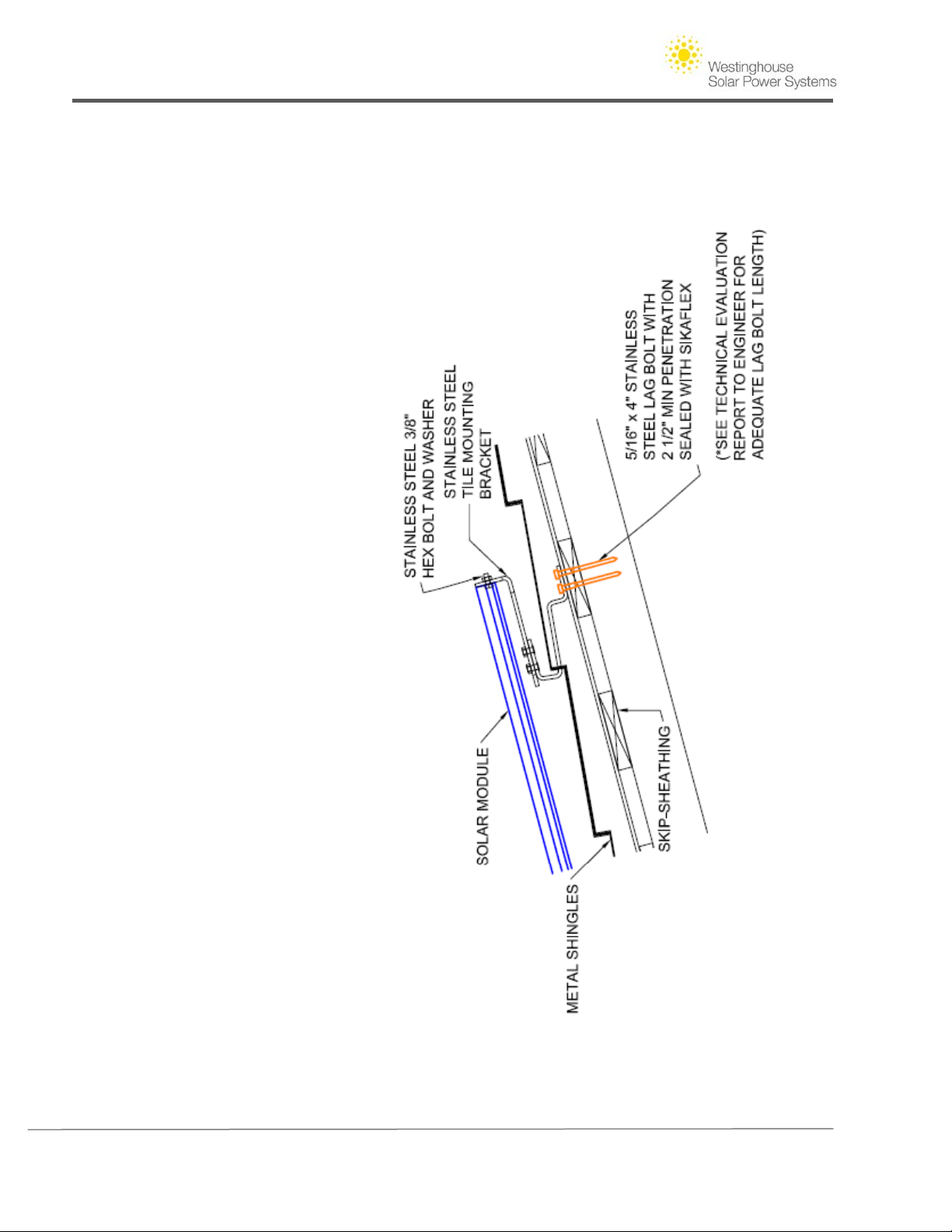
Westinghouse Solar AC Installation Guide
Copyright © 2011 - Westinghouse Solar vii | Page
Page 47
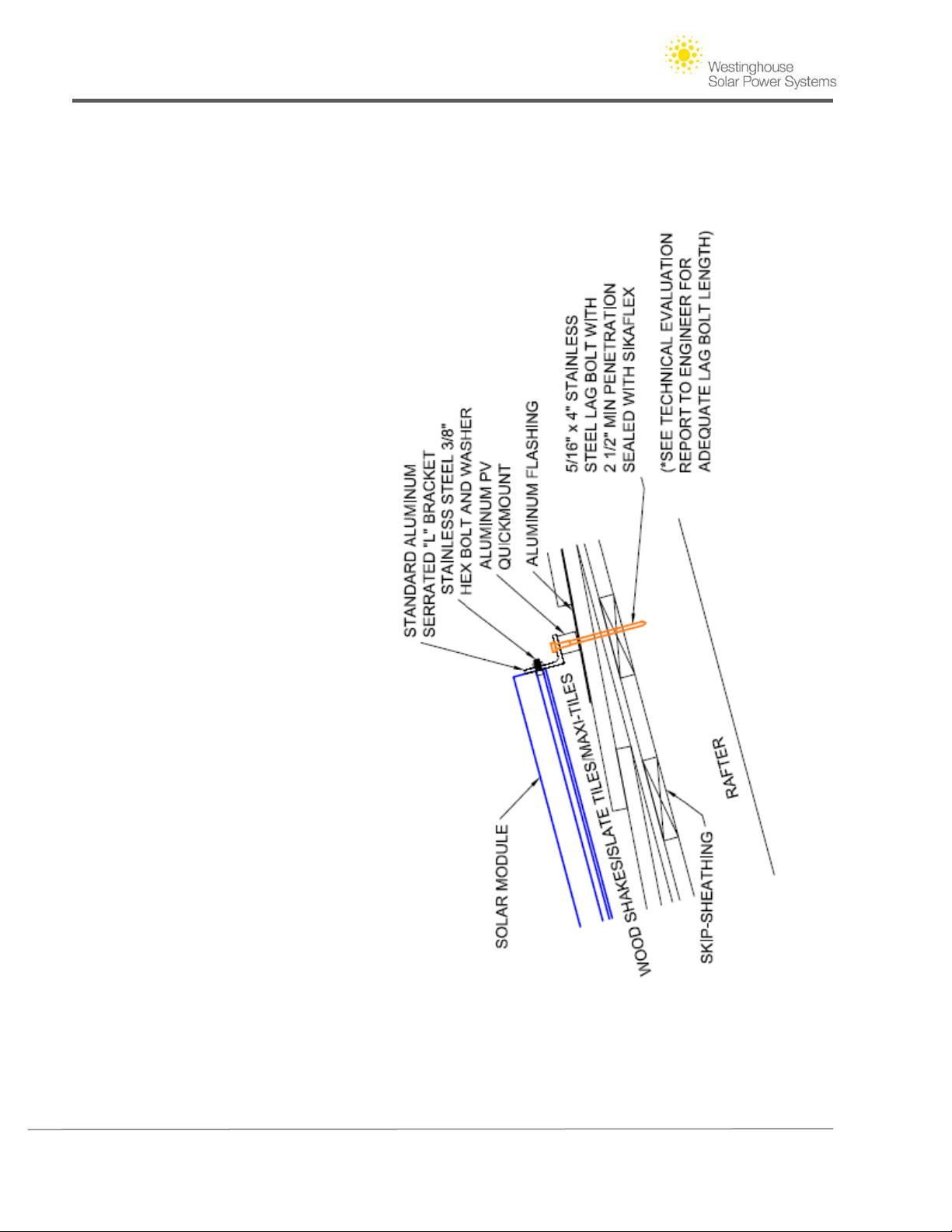
Westinghouse Solar AC Installation Guide
Copyright © 2011 - Westinghouse Solar viii | Page
Page 48
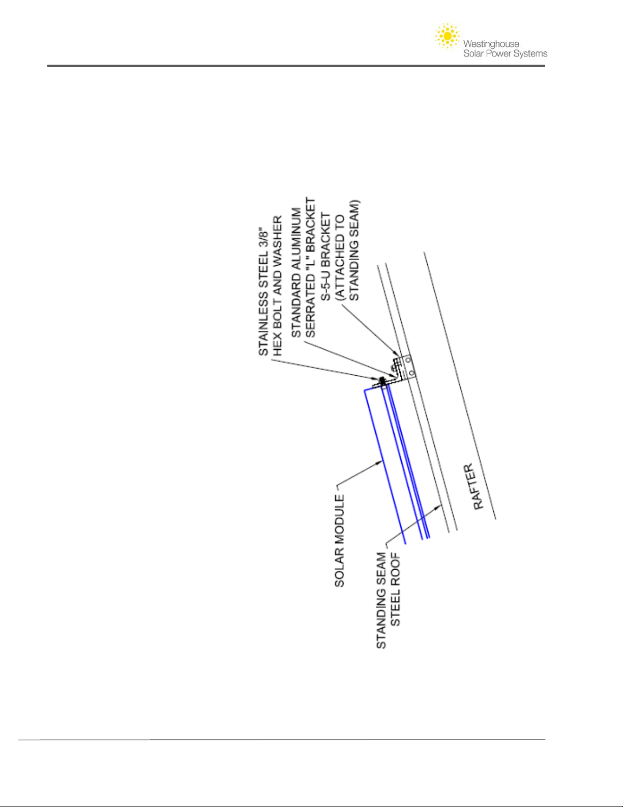
Westinghouse Solar AC Installation Guide
Copyright © 2011 - Westinghouse Solar ix | Page
Page 49
Westinghouse Solar AC Installation Guide
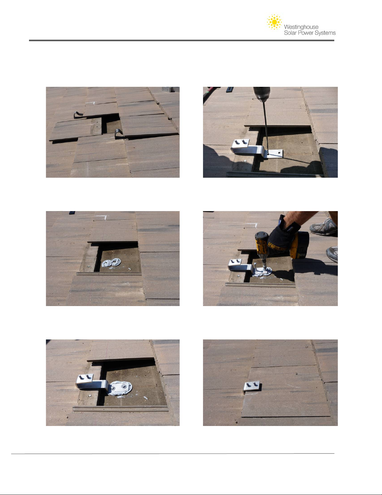
Installing flat concrete/ cement roof tile hardware
Step 1. Remove a tile at roof attachment location. Step 2. Predrill using flat tile bracket as a
template at rafter location.
Step 3. Apply roofing sealant to roof Step 4. Install Lag Bolts and washers to secure
penetration area. bracket in place.
Step 5. Replace previously removed tile at
attachment location.
Copyright © 2011 - Westinghouse Solar x | Page
Page 50
Westinghouse Solar AC Installation Guide
Installing "S" or Barrel Tile Roof Attachment hardware
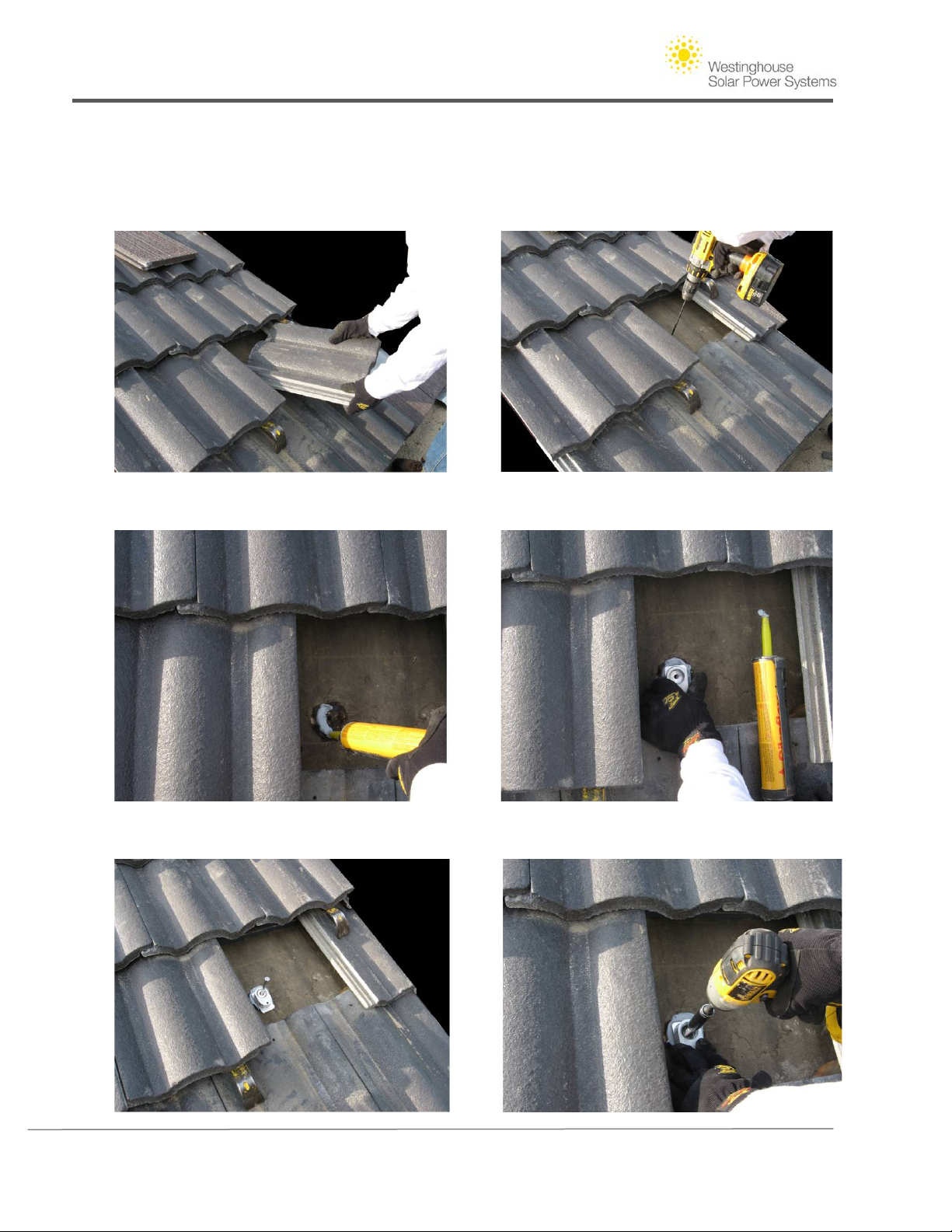
Step 1. Remove tile at attchment location. Step 2.predrill at rafter attachment location.
Step 3. Apply sealant to attachment location. Step 4. Place standoff base over pre-drilled hole.
Step 5. Using lag Bolt with included washer, attach standoff base to roof surface using an impact driver.
Copyright © 2011 - Westinghouse Solar xi | Page
Page 51
Westinghouse Solar AC Installation Guide
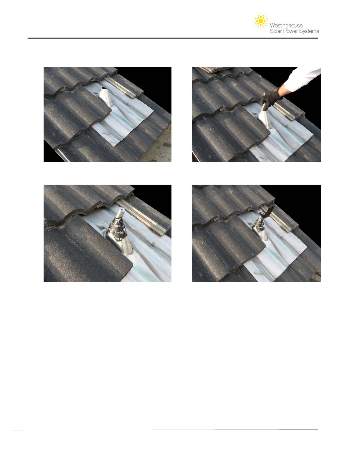
Step 6. Mold Flashing material to the profile of existing tiles. Install aluminum standoff into base once
flashing is in place.
Step 7. Seal flashing with vinyl roofing tape and loosely assemble assocated attachment hardware.
Copyright © 2011 - Westinghouse Solar xii | Page
Page 52

Westinghouse Solar AC Installation Guide
Section VIII. Technical Support
The following contact options are available for support of questions regarding product, installation, operation or
warranty of your Westinghouse Solar AC system:
Phone: 1.888.395.2248 (option 2)
Email:
Fax: Westinghouse Solar Tech Support - (408) 395-7979
Mail: Attention Westinghouse Solar Tech Support, 1475 South Bascom
Ave. Suite 101, Campbell, CA, USA, 95008
Copyright © 2011 - Westinghouse Solar xiii | Page
Page 53

Westinghouse Solar AC Installation Guide
Table of Figures
Figure 1 -– Westinghouse Solar AC System .................................................................................................. 2
Figure 2 - Roof attachment components and panel Groove example for composition shingle roof ........... 5
Figure 3 – Six by two array installed in portrait mode .................................................................................. 6
Figure 4 - Comparably sized four by three array in landscape mode ........................................................... 6
Figure 5 - Sample roof layout and panel dimensions................................................................................... 8
Figure 6 - Roof top buffer room example on composition shingle roof ....................................................... 9
Figure 7 - Offset L Bracket ............................................................................................................................. 9
Figure 8 - Basic Westinghouse Solar attachment point layout ................................................................... 10
Figure 9 - Profile of roof attachments with shared center attachment point across two panel rows ....... 11
Figure 10 - Westinghouse Solar inter-panel spacing and panel dimensions .............................................. 12
Figure 11 - Inverter components in a two row array .................................................................................. 15
Figure 12 - Single Branch Circuit Westinghouse Solar AC Wire Diagram ................................................... 17
Figure 13 – Laying out attachment points for Westinghouse Solar Modules ............................................ 19
Figure 14 - Tapping across assumed rafter location to find firmest point ................................................. 20
Figure 15 - Detail of Composition mount components pre and post installation ...................................... 23
Figure 16 - Westinghouse Solar Splice thread direction ............................................................................. 23
Figure 17 - Westinghouse Solar Splice thread direction ............................................................................. 24
Figure 18 - Single row of Westinghouse Solar modules installed ............................................................... 27
Figure 19 - Ground washers on the North/South Bracket ensure ground continuity across rows ............ 30
Figure 20 - Ground conductor applied to enable array grounding ............................................................. 30
Copyright © 2011 - Westinghouse Solar xiv | Page
Page 54

 Loading...