

Page 1
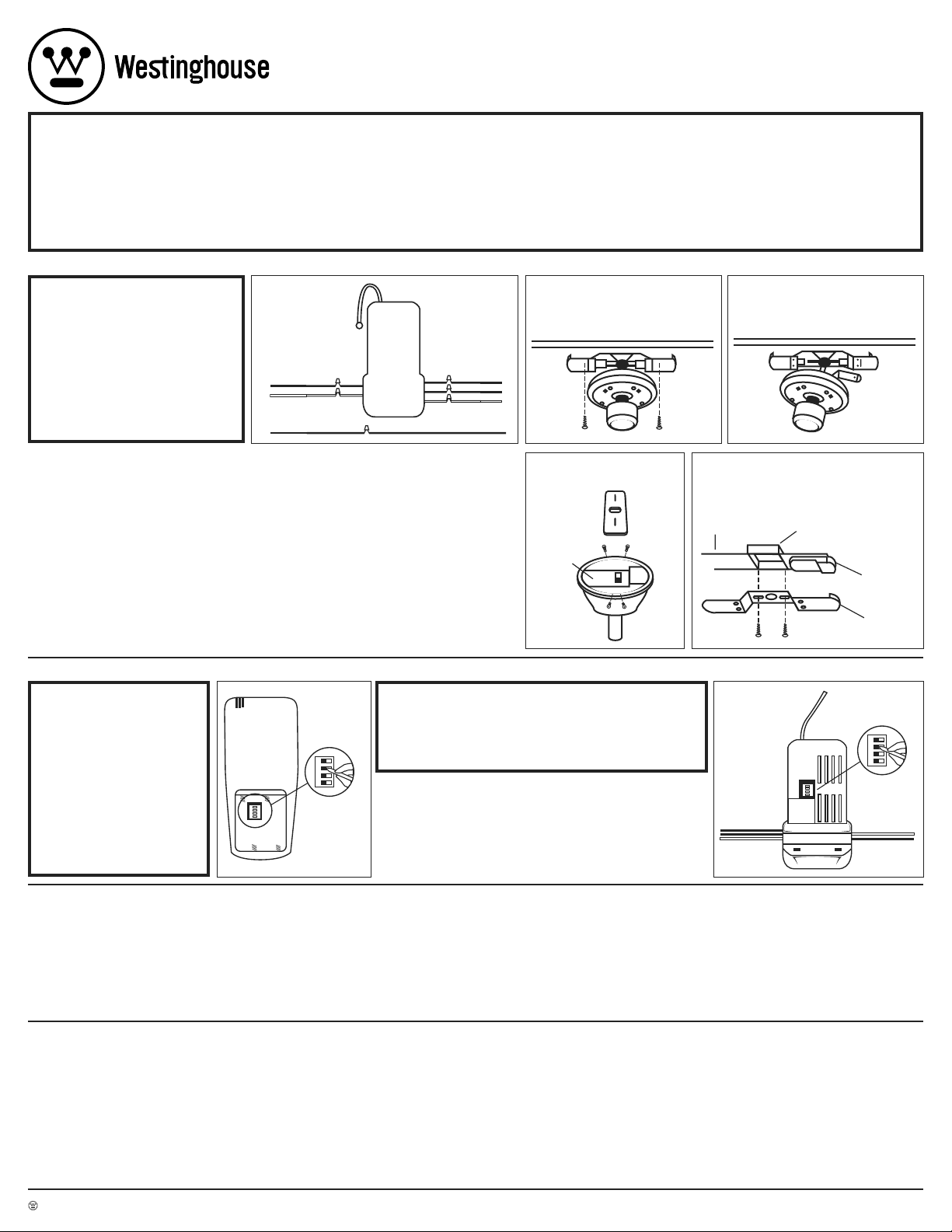
WIRES
CODE SWITCHE
S
1 2 3 4
1 2 3 4
RECEIVER
(CONTROLLER UNIT)
WIRES
WIRES
FIGURE 7
TRANSMITTER
(BACK OF REMOTE)
CODE SWITCHE
S
1 2 3 4
1 2 3 4
FIGURE 6
BLACK BLACK
WHITE WHITE
BLUE
RED BLACK
WHITE WHITE
BLUE
CONTROL
UNIT
LIGHT
FAN
FAN
AC SUPPLY
AC SUPPLY
BARE (GROUND) GREEN FAN
AC SUPPLY
FIGURE 1
FIGURE - 2
FLUSHMOUNT FANS ONLY
FIGURE - 3
FLUSHMOUNT FANS ONLY
CONTROL
UNIT
FIGURE - 4
DOWNROD FANS ONLY
CEILING
JUNCTION BOX
MOUNTING PLATE
CONTROL UNIT
FIGURE - 5
FLUSHMOUNT FANS ONLY
77870
Installation & Operating Instructions for the
Westinghouse Ceiling Fan and Light Remote Control
WARNING: SHUT POWER OFF AT FUSE OR CIRCUIT BREAKER
WARNINGS:
•
To avoid fire, shock, and serious personal injury, follow all
instructions carefully. Read and save these instructions for
future reference.
•
Do not install or use this unit if any part is damaged or miss-
ing.
•
IMPORTANT!
assembly of blades, before testing the remote control unit.
NOTICE:
1. This control is designed to operate only one ceiling fan with an
incandescent light kit.
Fan installation must be complete, including the
A. MAKING THE ELECTRICAL CONNECTIONS:
NOTE: This remote only works
with some fans in sloped ceiling
model.
Do not use fan speed control in
canopies where the mounting is
not as described in figures 4 or 5.
This remote cannot be installed in a
downrod style fan when in flushmount
mode (when downrod is not in use).
1. Disconnect existing wiring between ceiling fan and AC supply at electrical junction box.
2.
FOR FANS ON A DOWNROD:
from its mounting plate. Go to step 5.
FOR FLUSHMOUNT FANS:
from mounting plate (see figure 2). Disconnect mounting
bracket from mounting plate and allow to hang from one side
(see figure 3).
3. Making the electrical connection:
• Connect GREEN fan wire to BARE (ground) wire.
• Connect BLACK control unit wire to BLACK supply wire
(AC L).
• Connect WHITE control unit wire to WHITE supply wire
(AC N).
• Connect WHITE control unit wire (MOTOR N) to WHITE
fan wire.
• Push the connected wires up into the junction box.
BLACK wires on one side of box, and WHITE, GREEN
BARE (ground) wires on the other side of the box.
Remove ceiling fan canopy
Remove decorative housing
Place
and
SAFETY PRECAUTIONS:
2. This wall control is rated for a maximum (ceiling fan only) motor amp
of 1.0 at 120 volts, total (incandescent bulb only) wattage equaling 240
watt maximum.
3. Do not use with solid state ceiling fans.
4. The decorative housing (canopy) at the ceiling must be metal.
The metal housing acts as a protective cover for the Control Unit.
DO NOT USE WITH A NON-METALLIC HOUSING.
5. Only the remote unit should be used to change fan speeds. Do not use
the pull chain to change fan speeds after installation.
6. Make sure no bare wires are exposed outside of the connectors.
• Connect RED control unit wire (MOTOR L) to BLACK fan wire.
• Connect BLUE control unit wire (FOR LIGHT) to BLUE
light wire.
• Push the connected wires up into the junction box.
• Lay the BLACK control unit wire (ANTENNA) on top of the
control unit.
•
FOR FANS ON A DOWNROD:
canopy (see figure 4). Reinstall the canopy on its mount
ing plate. Restore electrical power to the circuit.
• FOR FLUSHMOUNT FANS:
the mounting plate or to the ceiling with the supplied tie
wraps (see figure 5). Reconnect the mounting bracket to
the mounting plate (see figure 2). Reinstall the decorative
housing on its mounting plate. Restore electrical power to
the circuit.
NOTE: If the unit does not fit properly between the
mounting plate and ceiling, attach the unit to the
underside of the mounting plate.
Lay the control unit in the
Attach the control unit to
-
7. All wiring must conform to national and local electrical codes. If you
feel that you do not have enough electrical wiring knowledge or experi
ence, have your fan control installed by a licensed electrician.
electrical work not described in this manual should be performed
by a licensed electrician.
8. Do not use water or detergents to clean the remote transmitter unit. A
dry dust cloth will be suitable for most cleaning.
9. Use of this control with some ceiling fans could result in fire, shock,
and serious personal injury. Use this fan control only with capacitor
speed controlled ceiling fans only.
Any
-
B. INSTRUCTIONS FOR YOUR NEW WESTINGHOUSE REMOTE FAN CONTROL SYSTEM
NOTE: Before installing this
unit, change the factory code
switch setting to your own
preferred setting.
Be sure the code switch positions of the transmitter and
receiver match each other or
the ceiling fan will not function.
If this unit causes interference with other appliances,
you may need to select
different combinations.
WARNING: HIGH VOLTAGE
Before connecting this control unit:
• Disconnect electrical power from the circuit to be used.
• Household power can cause serious injury or death.
• Wiring must meet all local electrical code requirements.
1. Setting the code on your new remote (see figure 6).
• Remove battery cover. Press firmly below arrow and slide battery cover off.
2. Slide code switches to your choice of UP and DOWN positions (use ball point
pen or small screwdriver to slide firmly up or down). Factory setting is all UP.
Do
NOT
use this setting.
3. Setting the code on your new control unit (see figure 7).
• Slide code switches to the same positions as set on your REMOTE.
NOTE: The code switches on the transmitter and the receiver unit must be set to
the same positions to work.
C. SETTING THE OPERATING CONTROLS (FIRST TIME ONLY):
1. This unit operates on one 9 volt battery (included).
2.
Store the controller unit away from excess heat or humidity.
3. This remote control unit is equipped with 16 code combinations.
Because of the many combinations, interference from other remotes
is possible (i.e. garage openers, car alarms, security systems, etc.).
If your fan/light goes on or off without using your remote, change the
codes on both the control unit in the fan and in your remote transmitter.
4. If your ceiling fan is equipped with variable speed and light ON/OFF pull
chain switch controls, make sure to set the speed control at the
speed and the light to the
TROUBLESHOOTING GUIDE
PROBLEM: REMOTE FAILS TO OPERATE
Check:
• Is there power to the control unit?
• Is the control unit wired correctly?
• Are the fan and light switches set on the highest position?
• Is there a good battery in the remote? If the red indicator lights when either
•
PROBLEM: SHORT RANGE
Solution:
•
Westinghouse Lighting Corporation, Philadelphia, PA 19154-1099, U.S.A. • Westinghouse Lighting Corporation, a Westinghouse Electric Corporation licensee • www.westinghouseceilingfans.com
and “Wesinghouse” are all registered trademarks of Westinghouse Electric Corporation • © 2004 WESTINGHOUSE LIGHTING CORP.
button is pushed, the battery is good.
Are the switches set the same in both the remote and the control unit?
If the remote can operate the control unit when close to it but does not operate it at distances of 30-50 feet, try placing the black antenna wire above the
ceiling and outside of the junction box.
ON or BRIGHTEST position before installing the
HIGHEST
wall control. This will avoid erratic speeds and possible damage to your
ceiling fan.
5. Operation buttons on the panel of the transmitter:
1 – FAN High speed
2 – FAN Medium speed
3 – FAN Low speed
0 – FAN Off
Light Bulb – LIGHT brightness and ON/OFF control
6. To turn ON the fan, press the selected speed button to run the fan at the
LIMITED WARRANTY
The Westinghouse remote control for ceiling fans offers a limited warranty of one year from the date of purchase to the original owner against
defects in material and workmanship. All spare parts are covered for
ninety days only. This warranty is in lieu of all other warranties expressed or
implied.
Westinghouse will repair or replace this remote control if it is defective due to faulty materials or workmanship. This warranty does not cover
service charges, batteries, defects resulting from accidents, damages caused
through abuse or alterations or by affixing any attachment not provided with
the product, improper installation or maintenance, failure of supporting
devices not supplied as original mounting hardware, exposures to extremes
of heat or humidity, incorrect voltage, surges in current,
desired speed.
7. To turn OFF the fan, press the “0” button.
8. For LIGHT control: Turn the LIGHT ON/OFF by pressing the light bulb
button. If you keep the light bulb button pressed, the LIGHT will dim,
go off, and come back on at the brightest level. The LIGHT will continue
to cycle until the light bulb button is released. If you turn your power
source off, the settings on your fan and lighting will not remain the same
when you turn the power back on.
unauthorized repair, or failures caused by modifications of the product or the
acts of third parties. See remote manual for proper installation.
If a warranty claim is made in the first year, simply return the remote with
a copy of the original sales receipt, freight prepaid to Westinghouse Lighting
Corporation, who, at its option, shall repair or replace the remote or refund
the purchase price.
damage.
Send all remotes and inquiries to:
If you have any questions regarding the installation of this item or the
warranty coverage, please call our consumer line at
representative will assist you.
Please pack product correctly to eliminate shipping
Westinghouse Lighting Corporation
Attn: Customer Service
12401 McNulty Road
Philadelphia, PA 19154-1099
1-888-417-6222
and a
Page 2
CABLEADO
INTERRUPTORES
DE CÓDIGO
1 2 3 4
1 2 3 4
RECEPTOR
(UNIDAD DE CONTROL)
CABLEADO
CABLEADO
FIGURA 7
TRANSMISOR
(PARTE POSTERIOR
DEL CONTROL REMOTO)
INTERRUPTORE
S
DE CÓDIGO
1 2 3 4
1 2 3 4
FIGURA 6
NEGRO NEGRO
BLANCO BLANCO
AZUL
ROJO NEGRO
BLANCO BLANCO
AZUL
UNIDAD DE
CONTROL
LÁMPARA
VENTILADOR
VENTILADOR
SUMINISTRO DE
CORRIENTE ALTERNA
SUMINISTRO DE
CORRIENTE ALTERNA
SUMINISTRO DE
CORRIENTE ALTERNA
SIN AISLACI N (TIERRA) VERDE VENTILADOR
FIGURA 1
FIGURA - 2
SÓLO VENTILADORES
DE MONGAJE AL RAS
FIGURA - 3
SÓLO VENTILADORES
DE MONGAJE AL RAS
UNIDAD DE
CONTROL
FIGURA - 4
SÓLO VENTILADORES
CON VARILLA VERTICAL
CIELO RASO
CASA DE EMPALMES
PLACA DE MONTAJE
UNIDAD DE CONTROL
FIGURA - 5
SÓLO VENTILADORES
DE MONGAJE AL RAS
77870
Instrucciones para la instalación y modo de empleo del
control remoto del ventilador de techo con lámpara Westinghouse
ADVERTENCIA: DESCONECTE EL SUMINISTRO DE ENERGÍA QUITANDO EL FUSIBLE O APAGANDO EL CORTACIRCUITO
ADVERTENCIAS:
• Siga las instrucciones al pie de la letra para evitar incendios, choques
eléctricos y lesiones personales graves. Lea estas instrucciones y
consérvelas para futura referencia.
• Si faltan piezas o hay piezas dañadas, no instale el ventilador.
•
¡IMPORTANTE!
control remoto el ventilador y las paletas deberán estar completamente
instalados.
AVISO:
1. Este control está previsto para operar un solo ventilador de techo con
adaptador para lámpara incandescente.
Antes de comprobar el funcionamiento de la unidad de
PRECAUCIONES DE SEGURIDAD:
2.
Este control tiene una capacidad nominal máxima de amperaje de motor
(únicamente el ventilador de techo) de 1.0 a 120 voltios, con un vataje total
(únicamente la lámpara incandescente) igual a 240 vatios máximo.
3. No lo utilice con ventiladores de techo de estado sólido.
4. El alojamiento decorativo (dosel) del techo debe ser de metal. El alojamiento de metal protege la unidad de control. NO LO UTILICE CON UN
ALOJAMIENTO QUE NO SEA DE METAL.
5. Para cambiar la velocidad del ventilador, utilice únicamente la unidad
de control remoto. No use la cadenilla de tiro para cambiar las veloci
dades del ventilador después de la instalación.
6.
Cerciórese de que ningún cable sin aislación quede fuera de los conectores.
A. EXPLICACIÓN PARA HACER LAS CONEXIONES ELÉCTRICAS:
NOTA: Este control remoto funciona
únicamente con algunos modelos
de ventilador para
techo inclinado.
No use el control de velocidad del
ventilador en doseles cuyo montaje
no se describe en las figuras 4 ó 5.
Este control remoto no se puede
instalar en ventiladores con varilla
vertical en montaje al ras (cuando
no se utilice la varilla vertical).
1. Desconecte el cableado existente entre el ventilador de techo y el
suministro de corriente alterna en la caja de empalmes eléctricos.
2.
SI EL VENTILADOR TIENE UNA VARILLA VERTICAL:
del ventilador de techo de la placa de montaje. Vaya al paso 5.
SI EL VENTILADOR ES DE MONTAJE AL RAS: Retire el alojamiento
decorativo de la placa de montaje (vea la figura 2). Desconecte la pieza de
fijación de la placa de montaje y deje que cuelgue (vea la figura 3).
3. Explicación para hacer las conexiones eléctricas:
• Conecte el cable VERDE del ventilador al cable SIN AISLACIÓN (el
cable de tierra).
• Conecte el cable NEGRO de la unidad de control al cable NEGRO
de suministro eléctrico (CA vivo).
• Conecte el cable BLANCO de la unidad de control al cable
BLANCO de suministro eléctrico (CA neutro).
• Conecte el cable BLANCO de la unidad de control (MOTOR
neutro) al cable BLANCO del ventilador.
• Introduzca los cables conectados dentro de la caja de empalmes.
Coloque los cables NEGROS en un lado de la caja y los cables
BLANCO, VERDE y SIN AISLACIÓN (de tierra) en el otro lado de
la caja.
Retire el dosel
• Conecte el cable ROJO de la unidad de control (MOTOR
vivo) al cable NEGRO del ventilador.
• Conecte el cable AZUL de la unidad de control (PARA LA
LÁMPARA) al cable AZUL de la lámpara.
•
Introduzca los cables conectados dentro de la caja de empalmes.
• Coloque el cable NEGRO de la unidad de control (ANTENA)
sobre la unidad de control.
•
SI EL VENTILADOR TIENE UNA VARILLA VERTICAL:
unidad de control en el dosel (vea la figura 4). Reinstale el dosel en
placa de montaje. Conecte el suministro eléctrico del circuito.
•
SI EL VENTILADOR ES DE MONTAJE AL RAS:
la unidad de control en la placa de montaje o en el techo
con las cintas de amarre suministradas (vea la figura 5).
Reconecte la pieza de fijación a la placa de montaje (vea la
figura 2). Reinstale el alojamiento decorativo en la placa de
montaje. Conecte el suministro eléctrico del circuito.
NOTA: Si la unidad no cabe correctamente entre la
placa de montaje y el cielo raso, monte la unidad en
la parte inferior de la placa de montaje.
Coloque la
Instale
B. INSTRUCCIONES PARA EL NUEVO SISTEMA DE CONTROL REMOTO DE VENTILADOR
NOTA: Antes de instalar la unidad,
cambie la configuración de fábrica
del interruptor de código a la
configuración que desee. Verifique
que la posición de los interruptores
de código del transmisor y del
receptor sea idéntica, pues de lo
contrario el ventilador no funcionará. Si esta unidad causa interferencia con otros electrodomésticos,
probablemente tendrá que seleccionar otra combinación.
ADVERTENCIA: ALTA TENSIÓN
Antes de conectar esta unidad de control:
• Desconecte el suministro eléctrico del circuito que utilizará.
• La tensión residencial puede causar lesiones graves o la muerte.
• El cableado debe cumplir con los códigos eléctricos locales.
1. Configuración de los códigos del nuevo control remoto (vea la figura 6).
• Retire la cubierta de las pilas. Para quitar la cubierta de las pilas, oprima con
firmeza debajo de la flecha a la vez que la desliza.
2. Ajuste los selectores de código hacia ARRIBA o hacia ABAJO según corresponda
con un bolígrafo o un destornillador pequeño. En la fábrica se configuran todos
hacia ARRIBA.
3. Configuración del código de la nueva unidad de control (vea la figura 7).
• Coloque los interruptores de código en las mismas posiciones que en el REMOTO.
NOTA: Los interruptores de código del transmisor y del receptor deben estar en
la misma posición para funcionar.
NO
use esta configuración.
7.
Todo el cableado debe cumplir con los códigos eléctricos nacionales y
locales. Si piensa que no tiene suficientes conocimientos o experiencia en
cableado eléctrico, acuda a un electricista certificado para que le instale el
control del ventilador.
este manual deberá ser realizado por un electricista certificado.
8. No use agua ni detergentes para limpiar la unidad de transmisión
remota. Basta limpiarla con un paño suave y seco.
9. El empleo de este control podría causar incendio, choque eléctrico y
-
lesiones personales graves cuando se utiliza para controlar algunos
ventiladores de techo. Use este control de ventilador únicamente con
ventiladores de techo de velocidad controlada por condensador.
la
Todo trabajo eléctrico que no se describe en
C. CONFIGURACIÓN DE LOS CONTROLES DE MANDO (SOLAMENTE LA PRIMERA VEZ):
1. Esta unidad funciona con una sola pila de 9 voltios (incluida).
2.
Guarde la unidad de control en un lugar protegido contra el calor o humedad excesivos.
3.
Esta unidad de control remoto está equipada con 16 combinaciones de códigos.
Debido a la gran cantidad de combinaciones, es posible que otras unidades de
control remoto pudieran causar interferencia (por ejemplo, abrepuertas, alarmas
de auto, sistemas de seguridad, etc.). Si el ventilador o la lámpara se enciende o
se apaga sin que usted utilice el control remoto,
de control del ventilador y en el transmisor remoto.
4. Si el ventilador de techo está equipado con controles de encendido/apagado
de cadenilla de tiro y velocidad variable, ponga el control de velocidad en la
GUÍA PARA SOLUCIONAR PROBLEMAS
PROBLEMA: EL CONTROL REMOTO NO FUNCIONA
Revise:
• ¿Le está llegando electricidad a la unidad de control?
• ¿Es correcto el cableado de la unidad de control?
• ¿Están en la posición más alta los interruptores del ventilador y de la lámpara?
• ¿Está buena la pila del control remoto? Si el indicador rojo se enciende cuando
oprime cualquiera de los botones, significa que la pila está buena.
• ¿Están en la misma posición los interruptores del control remoto y de la unidad
de control?
PROBLEMA: POCO ALCANCE
Solución:
•
Si control remoto puede controlar la unidad a poca distancia pero no funciona
desde 9 a 12 metros (30-50 pies) de distancia, pruebe colocar el cable negro
de la antena encima del cielo raso y fuera de la caja de empalmes.
Westinghouse Lighting Corporation, Philadelphia, PA 19154-1099, U.S.A. • Westinghouse Lighting Corporation, a Westinghouse Electric Corporation licensee • www.westinghouseceilingfans.com
y “Wesinghouse” son marcas registradas de Westinghouse Electric Corporation • © 2004 WESTINGHOUSE LIGHTING CORP.
cambie los códigos en la unidad
velocidad
MÁS ALTA y la lámpara en la posición de ENCENDIDO o MÁS
BRILLANTE antes de instalar el control de pared. De esta manera evitará las
velocidades erráticas y la posible avería de su ventilador de techo.
5. Botones de control del panel del transmisor:
1 – Para velocidad rápida del VENTILADOR
2 – Para velocidad mediana del VENTILADOR
3 – Para velocidad baja del VENTILADOR
0 – Para apagar el VENTILADOR
Lamparas –
GARANTIA LIMITADA
El control remoto para ventiladores de techo de Westinghouse le ofrece
al propietario original una garantía limitada de un año, a partir de la fecha
de compra, contra materiales y mano de obra defectuosos. Todas las piezas
de repuesto están cubiertas por noventa días solamente. Esta garantía reem
plaza a todas las otras garantías expresas o implícitas.
Westinghouse reparará o reemplazará este control remoto en caso de
defectos ocasionados por materiales o mano de obra defectuosos. Esta
garantía no cubre los gastos de reparación, pilas, defectos resultantes de
accidentes, averías ocasionadas por uso indebido o alteraciones o por la
instalación de cualquier accesorio que no sea suministrado con el producto,
instalación o mantenimiento incorrectos, falla de dispositivos de soporte no
suministrados con los herrajes de montaje originales, exposición a cambios
bruscos de temperatura o humedad, voltaje incorrecto, cambios de tensión,
reparaciones no autorizadas o fallas causadas por
Para el control de brillo de la LÁMPARA y ENCENDIDO / APAGADO
6. Para ENCENDER el ventilador, oprima el botón de velocidad deseado.
7. Para APAGAR el ventilador, oprima el botón “0”.
8.
Para controlar la LÁMPARA: La LÁMPARA se ENCIENDE/APAGA oprimiendo
el botón de lámpara. Si mantiene el botón de lámpara oprimido, la LÁMPARA
se atenúa, se apaga y se vuelve a encender en el nivel de mayor luminosidad.
La LÁMPARA continuará este ciclo hasta que suelte el botón de lámpara. Si
desconecta el suministro eléctrico, cuando lo vuelva a conectar perderá la
configuración del ventilador y de la lámpara.
modificaciones al producto o intervenciones de terceros. Consulte el
manual del control remoto para su instalación correcta.
Si hace un reclamo de garantía dentro del primer año, simplemente envíe
el control remoto con una copia del recibo original de compra, con franqueo
prepago a Westinghouse Lighting Corporation, que a su discreción reparará o
-
reemplazará el control remoto o reintegrará el precio de compra.
lar el producto adecuadamente para evitar daños durante el transporte.
Envíe el control remoto y dirija todas sus preguntas a:
Si tiene dudas acerca de la instalación de este artículo o de la cobertura
de la garantía, llame a nuestro Centro de atención al consumidor al
417-6222
Westinghouse Lighting Corporation
donde le ayudará un representante capacitado.
Attn: Customer Service
12401 McNulty Road
Philadelphia, PA 19154-1099
Sírvase emba-
1-888-
Page 3

AVERTISSEMENTS :
FILS
COMMUTATEURS
DU RÉCEPTEUR
(L’APPAREIL
DE COMMANDE)
1 2 3 4
1 2 3 4
FILS
FILS
FIGURE 7
COMMUTATEURS
DU TRANSMETTEUR
(PARTIE ARRIÉRE DE
LA TÉLÉCOMMAND)
1 2 3 4
1 2 3 4
FIGURE 6
NOIR NOIR
BLANC BLANC
BLEU
ROUGE NOIR
BLANC BLANC
BLEU
BLOC DE
RÉGLAGE
ÉCLAIRAGE
VENTILATEUR
VENTILATEUR
ALIMENTATION CA
ALIMENTATION CA
NU (MISE Á LA TERRE) VERT VENTILATEUR
ALIMENTATION CA
FIGURE 1
FIGURE - 2
MONTAGE ENTASTRÉ
SEULEMENT
FIGURE - 3
MONTAGE ENTASTRÉ
SEULEMENT
BLOC DE RÉGLAGE
FIGURE - 4
MONTAGE PAR LA TIGE
INFÉRIEURE SEULEMENT
PLAFOND
BOÎTE DE
RACCORDEMENT
PLAQUE
DE FIXATION
BLOC DE
RÉGLAGE
FIGURE - 5
MONTAGE ENCASTRÉ
SEULEMENT
• Afin d’éviter les incendies, les chocs électriques et les blessures corporelles, suivez attentivement toutes les instructions. Lisez et conservez
ces instructions aux fins de référence ultérieure.
• N’installez pas ou n’utilisez pas cet appareil s’il manque une pièce ou
qu’une pièce est défectueuse.
•
IMPORTANT!
l’assemblage des lames, avant de tester la télécommande.
AVIS-:
1. Cette commande est conçue pour faire fonctionner un seul ventilateur
de plafond, avec élément d’éclairage incandescent.
Terminez l’installation du ventilateur, y compris
B. RACCORDEMENT DES FILS ÉLECTRIQUES:
NOTE : Cette télécommande fonctionne
seulement avec certains modèles pour plafonds inclinés. Ne pas utiliser le dispositif
de commande de vitesse de ventilateur
si le montage du chapeau est différent de
celui illustré dans la figure 4 et 5. Cette
télécommande ne peut être utilisée avec
un ventilateur doté d’une tige inférieure,
lorsque celui-ci est encastré (quand la tige
inférieure n’est pas utilisée).
1.
Débranchez les fils se trouvant entre le ventilateur de plafond et
l’alimentation CA, à la boîte de raccordement électrique.
2.
MONTAGE PAR LA TIGE INFÉRIEURE: Retirez le chapeau du
ventilateur de plafond de sa plaque de fixation. Passez à l’étape 5.
MONTAGE ENCASTRÉ: Retirez le boîtier décoratif de la plaque
de fixation (voir figure 2).
plaque de fixation et suspendez-le d’un côté (voir figure 3).
3. Raccordement des fils électriques-:
•
Raccordez le fil du ventilateur VERT au fil de mise à la terre NU.
• Raccordez le fil de l’appareil de commande NOIR au fil
d’alimentation électrique NOIR (CA L).
• Raccordez le fil de l’appareil de commande BLANC au fil
d’alimentation électrique BLANC (CA N).
• Raccordez le fil de l’appareil de commande BLANC (AU
MOTEUR N) au fil du ventilateur BLANC.
• Replacez les fils raccordés dans la boîte de raccordement.
Placez les fils NOIRS d’un côté de la boîte de raccordement
et les fils BLANC, VERT et NU (de mise à la terre) de l’autre
côté de la boîte de raccordement.
Détachez le support de montage de la
• Raccordez le fil de l’appareil de commande ROUGE (AU
• Raccordez le fil de l’appareil de commande BLEU (POUR
•
• Placez le fil de l’appareil de commande NOIR (ANTENNE)
• MONTAGE PAR LA TIGE INFÉRIEURE: Placez l’appareil
•
NOTE: Si la commande ne s’ajuste pas complètement
77870
Notice d’installation et d’utilisation de la télécommande du
ventilateur de plafond et de l’élément d’éclairage de Westinghouse
MISE EN GARDE : COUPER L’ALIMENTATION AUX FUSIBLES OU À LA BOÎTE DE
DISJONCTEURS
MOTEUR L) au fil du ventilateur NOIR.
L’ÉCLAIRAGE) au fil d’éclairage BLEU.
Replacez les fils raccordés dans la boîte de raccordement.
sur le dessus de l’appareil de commande.
de commande sur le chapeau (voir figure 4). Réinstallez le
chapeau sur sa plaque de fixation. Rétablissez l’alimentation
électrique au circuit.
MONTAGE ENCASTRÉ:
à la plaque de fixation ou au plafond à l’aide des attaches à
tête d’équerre fournies (voir figure 5). Rattachez le support de
montage à la plaque de fixation (voir figure 2). Réinstallez
le boîtier décoratif sur sa plaque de fixation. Rétablissez
l’alimentation électrique au circuit.
entre la plaque de fixation et le plafond, attachez la
commande sur le dessous de la plaque de fixation.
MESURES DE PRÉCAUTION:
2.
La puissance nominale de cet appareil de commande (seulement le ventilateur de plafond) est de 1.0 A, à 120 V, et le wattage de l’ampoule (seulement
une ampoule incandescente) ne doit pas excéder 250 W.
3. N’utilisez pas avec les ventilateurs de plafond à semi-conducteurs.
4.
Le boîtier décoratif (le chapeau) situé sur le plafond doit être en métal.
Le boîtier en métal sert de couverture protectrice pour l’appareil de com
mande. NE PAS UTILISER AVEC UN BOÎTIER NON-MÉTALLIQUE.
5. Seule la télécommande doit être utilisée pour changer la vitesse du
ventilateur. N’utilisez pas les chaînes pour changer la vitesse du venti
lateur, après l’installation.
6.
Assurez-vous qu’aucun fil nu n’est exposé à l’extérieur des connecteurs.
Attachez l’appareil de commande
7.
Les câbles électriques doivent être conformes aux codes national et local
d’électricité. Si vous croyez ne pas avoir suffisamment de connaissances
ou d’expérience en matière d’électricité, faites installer cette commande de
ventilateur par un électricien agréé.
décrit dans ce manuel doit être réalisé par un électricien agréé.
-
8. N’utilisez pas d’eau ou de détergents pour nettoyer l’appareil de télétransmission. Un chiffon à poussière sec suffira à le nettoyer.
9.
L’utilisation de cet appareil de commande avec certains ventilateurs de plafond
-
pourrait causer un incendie, un choc électrique et de graves blessures person
nelles. Utilisez cette télécommande de ventilateur uniquement avec les ventila
teurs de plafond dont la vitesse est commandée par un condensateur.
Tout travail d’électricité qui n’est pas
-
-
A. INSTRUCTIONS POUR VOTRE NOUVELLE TÉLÉCOMMANDE POUR VENTILATEUR
NOTE : Avant d’installer
cet appareil, changez les
paramètres réglés en usine.
Assurez-vous que les positions des commutateurs de
l’émetteur et du récepteur
correspondent, sinon le ventilateur de plafond ne fonctionnera pas. Si cet appareil interfère avec d’autres appareils,
vous devrez peut-être choisir
une combinaison différente.
C. RÉGLAGE DE L’APPAREIL DE COMMANDE (SEULEMENT LA PREMIÈRE FOIS):
1. Cet appareil utilise une pile de 9 volts (incluse).
2.
Gardez l’appareil de commande à l’abri des chaleurs extrêmes ou de l’humidité.
3. Cette télécommande est dotée de 16 combinaisons de code. A cause de ces
combinaisons, l’appareil peut interférer avec d’autres télécommandes (c.-à-d.,
télécommandes d’ouvre-porte de garage, alarmes de voiture, systèmes de sécu
rité etc.). Si votre ventilateur/élément d’éclairage se met en marche/s’arrête sans
télécommande, changez les codes sur l’appareil de commande du ventilateur et de
votre appareil de télétransmission.
4. Si votre ventilateur de plafond est doté d’une chaîne permettant de contrôler les
vitesses et d’allumer ou d’éteindre l’élément d’éclairage, assurez-vous de régler la
GUIDE DE DÉPANNAGE
PROBLÈME: LA TÉLÉCOMMANDE NE FONCTIONNE PAS
Vérifiez les éléments suivants:
• L’appareil de commande est-il alimenté en énergie ?
• Les raccordements de l’appareil de commande ont-ils été effectués correctement?
• Les commutateurs du ventilateur et de l’élément d’éclairage sont-ils réglés au
• La pile de la télécommande est-elle bonne ? If the red indicator lights when either
• Les commutateurs sont-il réglés à la même position à la fois dans la télécom
PROBLÈME-: PORTÉE TROP COURTE
Solution:
• Si la télécommande ne fait fonctionner l’appareil de commande uniquement
Westinghouse Lighting Corporation, Philadelphia, PA 19154-1099, U.S.A. • Westinghouse Lighting Corporation, a Westinghouse Electric Corporation licensee • www.westinghouseceilingfans.com
et “Wesinghouse” sont des marques déposées Westinghouse Electric Corporation • © 2004 WESTINGHOUSE LIGHTING CORP.
niveau le plus élevé ?
button is pushed, the battery is good.
mande et l’appareil de commande ?
lorsque vous êtes à courte distance de celle-ci et qu’elle ne fonctionne pas
lorsque vous êtes à des distances de 30 à 50 pi., essayez de placez le fil
d’antenne noir au plafond et à l’extérieur de la boîte de disjoncteurs.
5. Boutons de fonctionnement sur le panneau de l’émetteur-:
-
1 – le VENTILATEUR fonctionne au niveau le plus fort
2 – le VENTILATEUR fonctionne au niveau moyen
3 – le VENTILATEUR fonctionne au niveau le plus faible
0 – le VENTILATEUR s’arrête
Éclairage – Pour régler la LUMINOSITÉ et la fonction marche/arrêt
GARANTIE LIMITÉE
mande de Westinghouse pour ventilateurs de plafond. Cette garantie est offerte à
l’acheteur initial et couvre tout défaut de pièces ou de fabrication. Toutes les pièces
de rechange sont couvertes pendant quatre-vingt-dix jours seulement. La présente
garantie se substitue à toute autre garantie expresse ou tacite.
Westinghouse réparera ou au remplacera cette télécommande s’elle est sujette à
des défauts de matériaux ou de fabrication. Cette garantie ne couvre pas les frais de
service, les piles ou les défauts résultant d’accidents, de dommages causés par une
-
utilisation abusive de l’appareil ou des modifications apportées à ce dernier, ou en
raison de l’ajout de tout élément non fourni avec le produit, d’une installation ou d’un
entretien incorrect, en raison du mauvais fonctionnement des dispositifs de soutien
non fournis, comme de la quincaillerie originale de montage, en raison de l’exposition
à des chaleurs extrêmes ou à l’humidité, en raison d’une tension incorrecte, des
pointes de courant, des réparations effectuées par des réparateurs non autorisés, ou
en raison des pannes attribuables à la modification
MISE EN GARDE : HAUTE TENSION
Avant d’effectuer les raccordements de l’appareil de commande:
• Coupez l’alimentation électrique du circuit utilisé.
• L’électricité de la maison peut causer de graves blessures personnelles ou la mort.
• Les câbles électriques doivent être conformes aux codes national et local d’électricité.
1. Réglez les paramètres de votre nouvelle télécommande (voir figure 6).
• Retirez le couvercle de piles. Appuyez fermement sous la flèche et retirez le
couvercle de piles.
2. Placez ensuite les commutateurs à la position de votre choix UP ou DOWN (utilisez
un petit tournevis ou un stylo à bille pour faire glisser les commutateurs fermement
vers le haut ou vers le bas). Tous les réglages fixés en usine sont en position UP.
NE PAS
utiliser ces réglages.
3. Réglez les paramètres de votre nouvel appareil de commande (voir figure 7).
• Placez les commutateurs aux mêmes positions que ceux de la TÉLÉCOMMANDE.
NOTE : Pour le bon fonctionnement du ventilateur, les positions des commutateurs de l'émetteur et du récepteur doivent correspondre.
vitesse au niveau
FORTE, avant d’installer l’appareil de commande. Ceci évitera d’obtenir vitesses
irrégulières et peut-être d’endommager votre ventilateur de plafond.
Une garantie limitée d’un an à partir de la date d’achat est offerte sur la télécom-
LE PLUS ÉLEVÉ et la lumière en position ON ou LA PLUS
6. Pour mettre le ventilateur en MARCHE, appuyez sur le bouton de réglage de
vitesses choisi afin de régler la vitesse voulue.
7. Pour que le ventilateur s’arrête, appuyez sur le bouton «0».
8. Pour régler l’ÉCLAIRAGE : Pour ALLUMER/ÉTEINDRE la lumière, appuyez sur le
bouton ampoule. Si vous continuez à appuyer sur le bouton ampoule, la LUMIÈRE
baissera, s’éteindra et s’allumera au niveau le plus fort. La LUMIÈRE suivra ce cycle
tant que vous continuez à appuyer sur le bouton ampoule. Si vous coupez la source
d’alimentation, les paramètres de votre ventilateur et appareil d’éclairage ne seront
plus les mêmes quand vous rétablirez le courant.
du produit ou résultant des actes d’une tierce partie. Reportez-vous au manuel pour
connaître l’installation appropriée de la télécommande.
Lorsque la réclamation est faite pendant la première année d’utilisation, tout
simplement renvoyez la télécommande avec une copie du ticket de caisse original, frais
de transport prépayés, à Westinghouse Lighting Corporation qui, à son propre choix,
réparera ou remplacera la télécommande ou remboursera le montant du prix d’achat.
Merci d’emballer le produit correctement pour éviter le dommage pendant le
transport.
Merci d’envoyer toutes les télécommandes et vos questions à:
Westinghouse Lighting Corporation
Attn: Customer Service
12401 McNulty Road
Si vous avez des questions au sujet de l’installation de cet appareil ou de la
garantie, veuillez communiquer avec notre service à la clientèle, en composant
le
1-888-417-6222
Philadelphia, PA 19154-1099
et un représentant compétent vous aidera.
 Loading...