

Page 1

Westinghouse Canada
Electronics, Control and Distribution Products Division
Instruction Leaflet
30-471 (E)
Page 1
September, 1984
New Information
AUTOMATIC TRANSFER SWITCH
Robonic II Automatic
Transfer Switches
Operation and
Maintenance Manual
Index
Warranty ......................................... 2
Westinghouse Offices ..................... 3
General Description ........................4
Component Identification ................ 7
LRO Description ............................. 5
RO Description ............................... 6
PRO Description ............................. 6
Application Information ................... 7
Logic Control .................................. 7
Replacing Parts ............................ 13
Trouble Shooting Guide ................14
Recommended Maintenance ........ 14
Page 2

Instruction Leaflet
30-471 (E)
Page 2
Warranty
The company warrants the apparatus to be supplied hereunder to be
of the kind designated or specified. The company shall repair or
replace any defective part or parts, f.o.b. the company’s factory, repair
shop or warehouse, which prove to be defective under normal and
proper use within one year from the date of shipment, provided that
the purchaser gives the Company immediate written notice of any
such defect or defects. In no event (including, but not limited to the
negligence of the Company, it’s employees or agents) shall the
Company be liable for special or consequential damages or damages
for loss of use and on expiration of the Warranty period, any liability of
the Company shall terminate. This constitutes the only warranty of the
Company and no other warranty or condition, statutory or otherwise,
shall be implied.
IMPORTANT
Check equipment for shipping damage immediately on receipt. In
case of damage call the carriers concerned at once for inspection,
and request an inspection report. Do not write to us first - notify
the carrier instead. If this precaution is not taken we cannot assist
you in recovering the amount of the claim against the carrier.
Page 3

Instruction Leaflet
30-471 (E)
Page 3
For Supply
Westinghouse industrial products, and a complete line of electrical construction products, are
distributed across Canada by WESCO (Westinghouse Sales & Distribution Company). For product
application, delivery or pricing information, call the WESCO office nearest you.
WESCO Sales Office
St. John’s 726-9073 95 O’Leary Ave, Regina 525-5841 1625-8th Avenue
Halifax 454-5851 3377 Kempt Rd. Saskatoon 242-1296 509-44th St E.
Moncton 854-8600 400 Edinburgh Dr. Calgary 253-7561 810-59th AveSE
Chicoutimi 549-0368 1533, boul. Talbot Calgary 253-756 11316-11th Ave SW
Montreal 631-9471 2125, 23 ave. Edmonton 452-7920 14760-116th Ave NW
Quebec 656-1025 2385, rue Watt Edmonton 437-3660 4484-97 St NW
Rimouski 724-9224 170 rue industrielle Red Deer 343-2113 1-7743 - 50th Avenue
Sept-Iles 962-6552 253, avenue Joliette Abbotsford 859-3111 34446 S. Fraser Way
Hamilton 528-8811 1910 Barton St. E. Kamloops 374-2112 961A Laval Cresent
Kitchener 893-6630 10 Goodrich Drive Kelowna 860-3918 1936 Kent Road
London 1-800-265-8241 Nanaimo 758-1777 1809 Freemont Road
Ottawa 733-2500 1800 Bank St. Prince George 562-3306 2223 Nicholson St N.
Sarnia 336-0722 1127 N. McGregor St. Surrey 588-6501 13811-103rd Avenue
Sudbury 673-8413 48 Pacific Ave. Trail 368-6474 1050 Eldorado St.
Thunder Bay 622-0638 700 Norah Crescent Vancouver 688-0277 1000 Beach Avenue
Toronto 445-0550 840 York Mills Rd. Victoria 382-7265 481 Cecelia Road
Windsor 966-2300 59 Eugenie St. E. Burnaby 299-5566 6000 Lougheed Hwy.
Winnipeg 772-9401 1460 Ellice Avenue
Westinghouse products for electrical utilities are available through the listed Utility Sales offices.
Call the office nearest you.
For Service
Utility Sales Offices
Fredericton 454-6952 460-440King St. Winnipeg 772-9906 1460 Ellice Acve.
Halifax 422-4441 720 Barrington St Tower Calgary 265-1204 707-324 8th Ave SW
Montreal 842-2566 2723-1, Complexe Desjardins Edmonton 428-7540 516-10303 Jasper Ave
Toronto 595-9551 1012-790 Bay St. Burnaby 299-5566 6000 Lougheed Hwy.
Westinghouse Service Centres provide after-sales service, installation and start-up supervision,
also testing and inspection, system verification, field repairs, alignment and balancing, rewind of
all types of motors and generators, modification and rebuilding for all makes of electrical and
mechanical equipment. Call the centre nearest you for service at all hrs.
Service Centres
St. John’s 722-7282 89 O’Leary Ave, Sudbury 674-3356 48 Pacific Avenue
Dartmouth 469-8400 71 Wright Avenue Swastika 642-3252 Westinghouse Ave.
Sydney 562-2242 RR2 Marion Bridge Thunder Bay 577-4267 635 Mountdale Avenue
Moncton 382-4457 80 Enterprise St. Toronto 255-8551 55 Goldthorne Ave.
Campbellton 753-3590 144 Water Street Windsor 944-0121 4080 E.C. Row Ave. E.
Saint John 542-7708 71 Crown Street Winnipeg 775-8643 1460 Elice Avenue
Montreal 748-8811 180, rue Authier Regina 352-5606 545 Dewdney Ave. E.
Quebec 656-1026 2385, rue Watt Saskatoon 934-5251 800-47th Street E.
Sept-Iles 962-9803 180, rue Maltais Calgary 273-0991 1856 Centre Ave. S.E.
Chicoutimi 549-6968 1533 Boul. Talbot Edmonton 465-7541 8011 Davies Rd., NW
Hamilton 545-1151 717 Woodward Ave. Ft. McMurray 743-8123 8204 Fraser Avenue
Kingston 389-8565 637 Justus Drive Nanaimo 758-9171 2311 McCullough Road
Kitchener 744-1161 20 Alpine Court Prince George 562-5571 2235 Nicholson St N.
London 453-0470 45 Pacific Court Vancouver 278-9841 13300 Vulcan Way
St. Catharines 277-1020 475 Glendale Avenue
Sarnia 337-3285 348 Queen Street S.
You can be sure...if it’s Westinghouse
Page 4
Instruction Leaflet
30-471 (E)
Page 4
General Description
CSA Standard C22.2 No. 178-1978 defines an automatic transfer
switch as, “self acting equipment for transferring one or more load
conductor connections from one power source to another.” The same
Standard also gives definitions for type A and type B automatic transfer
switches. “Transfer” switch type A means an automatic transfer switch
that does not employ integral overcurrent devices.” “Transfer switch,
type B means an automatic transfer switch that (does) employ integral
overcurrent protection”. Westinghouse Robonics in type A are
equipped with special instantaneous magnetic only interrupter. The trip
settings of these special interrupter are set (and fixed) at higher than
standard values. They are intended to trip only if the upstream
protective device fails to clear a fault. Incorporating these special
magnetic only interrupter, a type A Robonic operates in exactly the
same way as a transfer switch not having this feature. In the event that
both devices trip, the Robonics control circuitry will automatically
initiate transfer to the alternate source. The transfer operation will reset
the “tripped” magnetic only interrupter. Information on instantaneous
trip value, interrupting, closing and withstand ratings, and recommendations for maximum upstream protective devices for type A Robonics,
are given in tables 1, 2, 3 on page 7. The information given in these
tables is necessary for proper application. Type B “Robonics” are
equipped with standard thermal-magnetic breakers which will provide
the required overload and short circuit protection. Type B Robonics can
also be built using Seltronic or SCB breakers which could include
ground fault tripping as well as overload and short circuit protection.
For application information or assistance with type B Robonics, refer to
Westinghouse.
The Robonic II provides automatic transfer of an electrical load to a
stand-by power supply in the event of drop or loss of voltage of any or
all phases of the normal power supply. Upon the restoration of the
normal supply, the electrical load is automatically re-transferred to the
normal power supply.
The transfer motor utilizes the power from the source to which the
electrical load is being transferred. The mechanism is also designed to
leave both breakers trip free in the closed position, permitting incorporation of the thermal and short-circuit protection in either or both
breakers. In the higher ampacity models, type RO and PRO, an alarm
switch contact is supplied. This contact is connected in the transfer
motor circuit to lock the motor circuit out of operation when the
breaker(s) trip on an overload or short-circuit condition. Then the
breaker has to be manually reset. Instructions for the reset procedure
are located on the front of the operating mechanism.
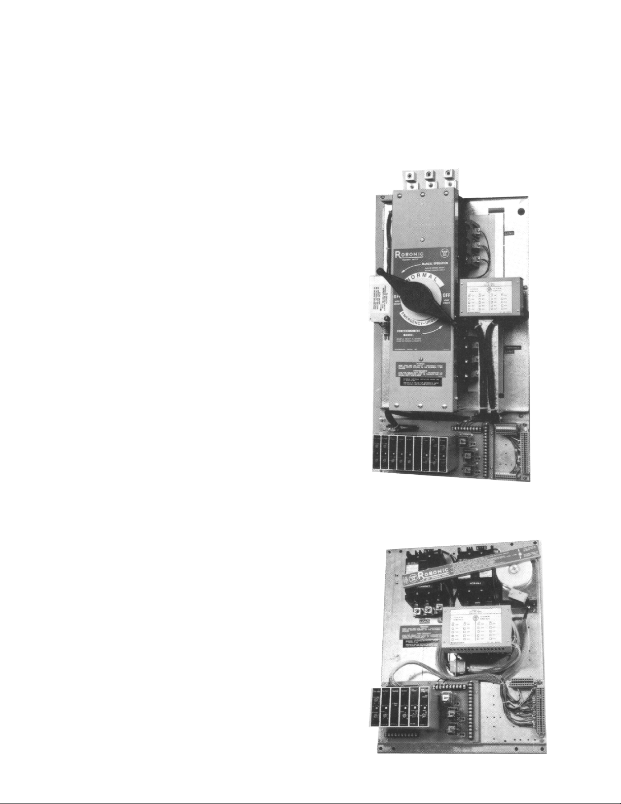
Mechanical Component Identification
Type RO
All of the control modules are plug-in units which are easily replaced.
Type LRO
Page 5
Solid State Logic Control Panel
Instruction Leaflet
30-471 (E)
Page 5
Type LRO Robonic II Automatic Transfer Switch
Rated 30 amperes through 100 amperes at 600 volts Ac maximum 50
or 60 Hertz.
The mechanism is a lever operated device controlled by a 120 volt
unidirectional motor.
The transfer motor drives a nylon cam which in turn operates a steel
lever by sliding a pin along a slot in the back of the lever. The lever, in
turn, operates the two breaker handles. The distance travelled is
determined by two projections on the cam. These projections operate
two micro switches (NLS, ELS) which in turn disconnect the power to
the transfer motor causing a brake to operate.
The type LRO has three operating positions. They are the normal
breaker closed and the emergency breaker open, the emergency
breaker closed and the normal breaker open or both the normal and
emergency breakers open but never both normal and emergency
breakers closed.
The type LRO can also be easily manually operated. Open the lever
cover, remove the slide pin and place it in the hole supplied in the lever
cover and close the cover. Then the lever can be manually operated for
what ever position desired without interference by the automatic
control. For automatic control again, simply align the lever slot with the
hole in the operating cam and replace the slide pin.
The various automatic control components are described under the
section titled “Logic Control”.
Emergency Normal
Pivot Post
Operating Arm
Projection To
Operate Limit Switch
Slide
Pin
Cam
Page 6

Instruction Leaflet
30-471 (E)
Page 6
Type “RO” Robonic II Automatic Transfer Switch
A complete line rated from 150 amperes through 1000 amperes at 600
volts Ac or at 250 volts Dc.
The transfer mechanism consists of the transfer motor, a gear train and
two breaker operating cams.
Scribe Line Scribe Line Scribe LineScribe Line
Spur Gear Meshing Relationship
(bottom view of top cover)
The transfer motor drives the centre gear which in turn operates the
two secondary gears. There is a projection in the secondary gears
which slides in a groove in the operating cams moving the cams from
side to side. The breaker handles are set inside two outer guides of the
cam and are also moved from side to side. There are two micro
switches (NLS, ELS) inside the breakers which are operated by the
breaker’s main contacts to disconnect the transfer motor power supply
and allow the brake to operate.
The type “RO” transfer switch has three operating positions, the normal
breaker closed and the emergency breaker open, the emergency
breaker closed and the normal breaker open or both the normal and
the emergency breakers open but never both the normal and emergency breakers closed at the same time.
Type “PRO” Robonic II Automatic Transfer Switch
Rated 1200 amperes through 3000 amperes at 600 volts Ac or 250
volts Dc.
The transfer mechanism consists of a transfer motor, a gear train and
two breaker operating cams.
Spur Gear Meshing Relationship
(bottom view of top cover)
The transfer motor drives a centre gear which in turn drives two inner
secondary gears. These two inner gears then drive larger, outer
secondary gears. There are projections from these outer secondary
gears which slide in a groove at the back of each operating cams
moving the cam up and down. The breaker handles are set inside two
outer guides on the cams, moving up and down with the cams. There
are two micro switches (NLS, ELS) inside the breakers which are
operated by the breaker’s main contacts to disconnect the transfer
motor power supply and allow the brake to operate.
The type “PRO” transfer switch has three operating positions, the normal
breaker closed and the emergency breaker open, the emergency
breaker closed and the normal breaker open or both the normal and
emergency breakers closed at the same time.
The type “RO” Robonic II Transfer Switch is also easy to operate
manually. Simply remove the transfer motor fuse and turn the black
handle on the front of the transfer mechanism in a counter clockwise
direction until you hear the breakers operated and the indicator is in the
desired position. There will be no interference from the solid state
control. For automatic control again, replace the transfer motor fuse
and the Robonic II transfer switch will seek the power available.
The various control components are described under the section titled
Logic Control.
The type “PRO” Robonic II Automatic Transfer Switch is also easy to
operate manually. Simply remove the transfer motor fuse and turn the
black handle on the front of the transfer mechanism in a counter-clockwise
direction until you hear the breakers operated and the colour indicator
shows the desired position. For automatic control again, replace the
transfer motor fuse and the Robonic II Transfer switch will seek the
power available.
The various control components are described under the section titled
Logic Control
Page 7

Instruction Leaflet
30-471 (E)
Page 7
Table 1 — Interrupting, Closing and Withstand Rating —
Robonic Type A
Robonic
Continuous
Rating Type 600 Vac 480 Vac 120,208,240 Vac
30 to 100 amps LRO 14,000 14,000 18,000
150 to 225 amps RO 22,000 22,000 25,000
300 to 1000 amps RO 22,000 30,000 42,000
1200 to 3000 amps PRO 65,000 65,000 125,000
rms symmetrical amperes
Since type A Robonics employ magnetic only breakers, their interrupting, closing and withstand ratings are the same value. Under fault
conditions, with it’s “normal” breaker closed, a Robonic is required to
withstand the energy let through of the normal service protective
device while the fault is being cleared. At the same time, should the
normal voltage fall below the voltage sensing relay’s selected value, and if the alternate source were available, the Robonic could transfer
before the normal service protective device cleared the fault.
This would require that the Robonic be capable of interrupting the
protective device’s let through current. In addition, the Robonic could
be required to close in on a fault. Thus can be seen the need for
Robonics to have, interrupting, closing and withstand ratings.
The interrupting, closing and withstand ratings shown in Table 1 are
those for standard type A Robonics. For higher values, consideration
can be given to use of Robonics built with Mark 75, Tri-Pac or SCB
breakers.
Table 2 — Maximum Upstream Circuit Protective Devices for
Type A Robonics, All Classes of Loads
Robonic Maximum Upstream Maximum Upstream
Type Continuous Breaker Frame Size Class Class
Rating J or L K5 or R
(amps)
LRO 30 EB, EHB, FB, HFB, FB-P 100 100
LRO 70 EB, EHB, FB, HFB, FB-P 100 100
LRO 100 FB, HFB 100 100
RO 150 CA,CAH,JA,KA,HKA,LC,HLC,LA-P 225 225
RO 200 DA, LBB, LB, HLB, LC, HLC, LA-P 225 225
RO 225 DA, LBB, LB, HLB, LC, HLC, LA-P 225 225
RO 300 DA, LBB, LB, HLB, LC, HLC, LA-P 400 400
RO 400 LA, HLA, LC, HLC, NB-P 400 400
RO 600 MA, HMA, MC, HMC, NB-P 600 600
RO 800 NB, HNB, NC, HMC, PB, PC, PB-P 800 ...
RO 1000 PB, PC, PB-P 1200 ...
PRO 1200 PB, PC, PB-P 1200 ...
PRO 1400 PB, PC 2000 ...
PRO 2000 PB, PC 2000 ...
¬ Fuse ratings given are as allowed by C.E.C. If other ratings are desired, refer to C.E.C.
Fuse-Rating¬
Table 3 — Maximum Upstream Circuit Protective Devices for
Type A Robonics, 90% or Larger Motor Load
Robonic Maximum Upstream Maximum Upstream
Fuse-Rating¬
Type Continuous Breaker Frame Size Class Class
Rating J or L K5 or R
(amps)
LRO 30, 70, 100 EB, EHB, FB, HFB, FB-P 300 100
LA-P c/w 400LAP10
RO 150,200,225 CA,CAH,JA,KA,HKA,LA,HLL,LB, 400 225
HLB, MA, NB, HLC, MC, HMC, NC,
HNC, LA-P, NB-P c/w 500 NAB12
RO 400 LB, HLB, LC, HLC, LA, HLA, LA-P 600 400
MA,HMA,MC, HMC, NB, HNP, NC,
MNC, NB-P
RO 600, 800 MA, HMA, MC, HMC, NB, MNB, NC, 1200 600
MNC, NB-P
RO 1000 NB, HNB, NC, HNC, PB-P 1200 ...
PRO 1200 NB,HNB,NC,HNC,PB-P 1200 ...
PRO 1400, 2000 PB, PC, PB-P 2000 ...
¬ Fuse ratings given are as allowed by C.E.C. If other ratings are desired, refer to C.E.C.
Logic Control
Voltage Sensing Modules
1Ø Undervoltage S# 1266C79G04 Option#5C, 26B
3Ø Undervoltage S# 1266C79G03 Option#5C, 26A
These cards are normally set at 70% dropout and 90% pickup.
1Ø Overvoltage S# 1266C79G02 Option#5B, 26C
3Ø Overvoltage S#12266C79G01 Option#5B, 26C
These cards are normally set at 105% pickup and 115% dropout. All
styles are applicable to both emergency and normal source monitoring.
Frequency Sensing Modules
1Ø Underfrequency S#1275C74G04 Option#5D, 26D
1Ø Overfrequency S#1275C74G06 Option#5E, 26E
Page 8

Instruction Leaflet
30-471 (E)
Page 8
Both under and overfrequency cards are factory calibrated at 60 Hz.
The actual values of pickup and dropout are as follows:
Type Dial Setting Pickup Dropout
Hz Hz Hz
Underfrequency 60 57 55
Underfrequency 50 47 45
Overfrequency 60 63 65
Overfrequency 50 53 55
Undervoltage / Underfrequency Module
S#1288C58G01 Option# 5A, 26F
Monitors one phase of power source.
Relay Driver
S#1266C77G02 Option#1A, 1B, 1C, 3A, 3B, 3C, 4A, 4B, 4C, 4D
This card is used in place of any of the timing modules when
instantaneous operation is required.
Blank
S#1266C77G01
Used to cover any unused card slots.
Time Delay Modules
1-60 sec. timer S#1275C74G01 Option#1A, 3A, 4A
0.1-10 min. timer S#1275C74G02 Option#1B, 3B, 4B
0.2-30 min. timer S#1275C74G03 Option#1C, 3C, 4C
5 min fixed S#1275C74G08 Option#4D
All can be used to accomplish TDEC, and TDNE functions.
All Cards Mechanically Interlocked
All cards are interlocked mechanically to prevent insertion into the
wrong function slot. All cards have a repeat accuracy over a 20 to
+60°C temperature change of (+ or -) 3%. Dial settings are (+ or -) 10%
of indication.
After making adjustments, tighten locking screw to secure setting.
Tighten mounting screws (screws are not captive).
Page 9

Instruction Leaflet
30-471 (E)
Page 9
Adjustments
Timer and frequency modules can be adjusted as per module front
plate. Voltage sensing modules can be adjusted as follows:
Undervoltage Module
Set Description
1 Set Dropout knob maximum Counter-clockwise
2 Set pick-up knob maximum Counter-clockwise
3 Increase line volts to desired Dropout value
(normally 70%) LED should be “ON”
4 Rotate Dropout Clockwise until LED goes “OFF”
5 Rotate Pick-up to maximum Clockwise LED is “OFF”
6 Increase line volts to desired Pick-up value
(normally 90%) LED is “OFF”
7 Rotate Pick-up knob Counter-clockwise until LED comes
“ON”
8 Re-check Pick-up and Drop-out by running voltage up and
down check by LED indication.
Overvoltage Module
Step Description
1 Set Dropout to maximum Counterclockwise
2 Set Pick-up to maximum Counterclockwise
3 Set line voltage to pull in value desired (normally
105%) LED is “OFF”
4 Rotate Pick-up Clockwise until LED comes “ON”
5 Rotate Dropout maximum Clockwise
6 Set line voltage to Dropout value desired
(normally 15%)
7 Rotate Dropout Counterclockwise until LED is
“OFF”
8 Drop line voltage to pull-in desired value. LED
should come “ON”
9 Increase line voltage to desired Dropout value.
LED should go “OFF”
The relay is incorporated in the control scheme to stop the transfer
switch with both breakers open. This is to allow residual load voltage
to decay prior to closing on another supply which could be out of
phase. When the timing cycle is complete, the relay re-initiates transfer
to the available source.
Time Delay Engine Starting Relay
Solid State Type Option #2A
Ratings - 1.2 Watts Power Consumption
Input coil voltage - 120 volts at 50/60 Hertz.
Contact Rating - 10 amperes resistive at 120 volts
Time Range - 2 to 3 seconds - nonadjustable.
Operating Temperature Range - -10oC to +55oC.
Pneumatic Type Option #2B
Rating - 8 Watts Power Consumption
Input Coil Voltage - 120 volts 50/60 Hertz.
Contact Rating - 10 amperes resistive at 120 volts Ac.
Time Ranges - Various available.
Operating Temperature Range - -30oC to +75oC.
DT and DTM Time Delay Relays Option #32A, 32B
Ratings - 6 Watts Power Consumption
Input coil Voltage - 120 volts
Contact Rating - 3 amperes at 220 volts Ac 50/60 Hertz
Operating Temperature Rating - -10oC to +50oC
Time Ratings - Various available
Page 10

Instruction Leaflet
30-471 (E)
Page 10
This time delay relay is an octual plug-in, sychronous motor type. It is
complete with clutch and mechanical load switch giving one instantaneously operated normally open contact and a timed single pole double
throw contact in a dust-tight grey capsule. The mechanism is constructed to operate for the time set on the indicating dial and then
disconnect itself when the timing cycle is complete. A red pilot light on
the face plate indicates that the relay is timing to operate its contacts.
When de-energized, the relay requires a reset time of at least 0.5
seconds. Time delay begins immediately upon energizing the coil.
When the timing cycle is complete, a mechanical latch holds the
contacts in position and the coil is de-energized.
Transformer Modules
Modules include all necessary control, voltage sensing and logic
transformers.
Plant Exerciser Option# 23A, 23B, 23C
Ratings - Input voltage 120 volts
Contact rating 20 Amps at 120 volts resistive S.P.D.T.
Description
Dial A is divided into a 24 hour day and night scale, and has tabs
around the periphery which may be adjusted to operate the micro
switch within intervals each 24 hours. Each tab represents a 15 minute
interval. Dial B has 7 spokes and advances one position for each
revolution of Dial A. Each spoke has provision to add a pin to operate
the micro switch. These pins represent days of the week and their
function is to prevent operation of the micro switches on selected days.
Application
The plant Exerciser is a Program Time Switch which functions to start
and stop the engine-generator set and transfer switch automatically at
pre-selected intervals or times. It consists of a synchronous electric
motor and a gear assembly to rotate a dial 360°C each day for a week
(168 hours). On the periphery of the dial there are levers or tabs which
can be set to operate a mechanical load switch as dial rotates. These
levers can be selected to operate the switch at specific times of the
day daily or specific days of the week. The cycle repeats weekly. The
Plant Exerciser may be used in two different ways as an accessory for
transfer switches.
1. It may to simulate an interruption in the normal source of supply at
selected intervals, at least once per week, causing the transfer
switch components to function, including start-up of the enginegenerator set and transfer of load to the generator supply. At the
end of the interval it will initiate the transfer back to normal supply
and shut down the engine-generator.
Two versions are available. The standard module has three phase
monitoring of the normal source and one phase monitoring of the
emergency source. The optimal module has three phase monitoring on
both the normal and emergency sources.
Page 11

or
2. It may be used to start an engine-generator set at selected
intervals, at least once per week, but without causing the transfer
switch to operate and transfer the load to the generator supply.
At the end of the interval it will cause the engine-generator to
shutdown.
INSTRUCTIONS — TO OPERATE THE ENGINE FOR AN INTERVAL
ONCE EACH WEEK, WITH OR WITHOUT OPERATION OF THE
TRANSFER SWITCH.
1. Extend the tabs of Dial A outwards, except those representing the
time of day for the running of the engine or operation of the
transfer switch.
2. Determine the day of the week for this testing. Install the six brass
pins (called skip pins) in the spokes of Dial B representing the
other six days of the week.
3. Turn Dial A counterclockwise until the special tab at 12:00 midnight
advances Dial B. Turn Dial B until present day of the week is
opposite the copper arrow. Turn Dial A counterclockwise until the
correct time of day (or night) is opposite the arrow on the nameplate.
4. If the interval of running the engine is desired more than one day
per week but at the same time of day, remove the skip pin from
the appropriate spoke of Dial B.
Caution
Instruction Leaflet
30-471 (E)
Page 11
Portable Test Kit #50
An inexpensive, portable test kit, #1278C67G01, is available for
convenient field testing and calibration of all plug-in cards and output
relays. The only power source required is a 120V convenience outlet.
A selector switch allows the operator to test individual cards or to
simulate ATS operation by having the source monitoring cards drive
the time delay cards which in turn drive the output relays, exactly as in
actual use. Calibration checks or changes can thus be accomplished
without necessity of energizing the alternate power source.
DO NOT insert skip pins in any spoke when that spoke is pointing
towards the copper arrow
Page 12

Instruction Leaflet
30-471 (E)
Page 12
Schematic of Robonic II Transfer Switch
Consider the Robonic II in the normal operating position, with normal
power available and the normal interrupter closed. The following are
energized: U.V. (undervoltage module), TDES (time delay engine
start), and NR (normal relay).
The U.V. monitoring all 3 phases of the normal power, senses a dip or
loss of voltage which instantly causes NR to deenergize. Contacts NR2
and NR4 open, and contacts NR1 and NR3 close. TDES times out,
closing it’s contacts and initiating the emergency system start up. When
the emergency system reaches correct levels of voltage and frequency,
ER is energized and contact ER2 closes. This completes the emergency
control circuit, and TM (transfer motor) begins to operate.
First, the normal interrupter is opened, and then the emergency
interrupter is closed. At this point, the ELS (emergency limit switch)
contacts change state, and the BS (motor brake) closes, preventing
TM over travel. The NLS (normal limit switch) contacts change state in
preparation for re-transfer to the normal power source.
Upon return of stabilized normal power, NR is re-energized disabling
the emergency control circuit, and enabling normal control circuit. The
TM operates, opening the emergency interrupter and closing the
normal interrupter. When the re-transfer is completed, the NLS contacts
change state isolating TM, and BS closes. TDES becomes energized
opening it’s contacts. TDEC times out to allow the emergency generator
to run unloaded and cool off before shutting down. The Robonic II is
now ready to react to another normal power failure.
Page 13

Instruction Leaflet
30-471 (E)
Page 13
Replacing Parts
The Robonic Automatic Transfer Switch has been designed to have all
components accessible and readily removable from the front of the
panels. The Robonic Transfer Switch is divided into two basic sections.
The upper section consists of the main contacts and transfer mechanism,
the lower section consisting of all the automatic control devices.
Caution
When replacing any parts of the mechanism, control transformers or
breakers, isolate the Robonic Transfer Switch from any possible source
of power.
To remove the transfer mechanism of the LRO transfer switch, first
open the cover and remove the slide pin from the operating cam, then
remove the centre bolt, the mechanism will lift straight off. The breakers
and transfer motor bracket are held by four screws for ease of removal
and replacement. When replacing the mechanism, first set it on the
Robonic with the breaker handles in the holes provided and then fasten
the centre bolt reasonably tight with the mechanism fully movable with
an equivalent swing distance up and down.
To remove the transfer mechanism of the RO transfer switch, remove
the four bolts holding it, taking note of which holes the bolts were in,
then lift the mechanism straight off. The breakers are held by two bolts
at one end and the bus connectors on the other end. The transfer motor
is mounted to the transfer mechanism cover and centre drive gear.
When replacing any part of the transfer mechanism, be sure that the
scribe lines of the gears are in a straight row (example shown on page 6).
To prevent operation of the transfer switch while replacing mechanism
or components, disconnect all sources of power.
When replacing the mechanism move it about until the breaker toggles
fit between the mechanism fingers and then fasten the bolts tightly. To
test for proper operation first operate manually and then connect 120
volt, 60 Hertz supply to motor leads and observe operation for free
movement and proper breaker operation.
The PRO transfer switch mechanism is similar to the RO with the
exception that the PRO mechanism has five gears and is mounted
horizontally. The breakers are fastened to the panel by six bolts.
All Robonic transfer switch breakers and mechanisms have allowed
some adjustments for mounting to assure proper operation without
slipping or binding. Be sure all hardware is tightened sufficiently before
re-energizing any transfer switch.
To replace any of the octal plug-ins relays, pull old units straight out
and insert the replacement unit. Due to the tight fit of the receptacle
and pins, you may have to move the relay about a little to pull it out.
DO NOT INTERCHANGE ANY RELAY WITH ANY OTHERS.
To replace any solid state logic modules, pull straight out and insert the
replacement unit.
Parts List
Part Name Style No.
Parts Common to Robonic II
Plug-in Modules
Timer,1-60 sec. adjustable, for TDEN,TDEC,TDNE 1275C74G01
Timer,0.1-10 min. adjustable, for TDEN,TDEC,TDNE 1275C74G01
Timer,0.2-30 min. adjustable, for TDEN,TDEC,TDNE 1275C74G03
Timer, 5 min. adjustable, for TDEN,TDEC,TDNE 1275C74G08
Relay driver — used in place of timers, for
instantaneous operation 1266C77G02
Instantaneous relay, used for NR,ER and EC 1Ø
under frequency module, for “normal” or “emergency 1275C74G04
1Ø over frequency module, for “normal” or “ermergency” 1275C74G06
3Ø over voltage module, for “normal” or “emergency” 1266C79G01
1Ø over voltage module, for “normal” or “emergency” 1266C79G02
3Ø under voltage module, for “normal” or “emergency” 1266C79G03
1Ø under voltage module, for “normal” or “emergency” 1266C79G04
Blank cover, for unused module space 1266C77G01
Time delay relay for engine starting, 2.5s fixed 3152A51H01
Time delay relay for engine starting, adjustable 1-300s 688A886H11
Options
Plant Exerciser 688A888G01
Battery Charger 12V 1259C26G01
Battery Charger 24V 1259C26G03
4 Position s/s fixed 7070A56H01
4 Position s/s keyed 7070A56H02
Transformer Modules Standard Optional
600V, for LRO, RO 160D997G05 160D997G15
480V, for LRO, RO 160D997G04 160D997G14
416V, for LRO, RO 160D997G03 160D997G13
240V, for LRO, RO 160D997G02 160D997G12
208V, for LRO, RO 160D997G01 160D997G11
600V, for PRO 160D997G10 160D997G20
480V, for PRO 160D997G09 160D997G19
416V, for PRO 160D997G08 160D997G18
240V, for PRO 160D997G07 160D997G17
208V, for PRO 160D997G06 160D997G16
For Type LRO Robonic II
Mechanism 833C222G02
Motor Assembly 833C223G01
Motor 688A732H02
Operating Cam 688A458G01
Slide Pin 688A731H01
Limit Switch 688A747H01
For Type RO Robonic II
Mechanism 150 to 400A 833C226G01
Mechanism 600 to 1000A 833C226G01
Motor 688A749H01
Solenoid 688A740H01
Brake Shoe Assembly 688A738G01
Operating Cam 572B774H01
Auxiliary & Limit Switch 688A747H01
For Type PRO Robonic II
Mechanism 688A109G01
Motor 688A749H02
Solenoid 688A740H01
Auxiliary & Limit Switch 688A747H01
Page 14

Instruction Leaflet
30-471 (E)
Page 14
Trouble Shooting Guide
Symptoms
• refusal to re-transfer to normal
source upon restoration
• will not transfer to emergency
source upon failure of normal
source
• transfer without a power failure
in the normal source
• no time delay when there
should be
• engine-generator starts when
the normal source has not
failed
Possible Causes
• a voltage sensing relay did not
energize
• emergency to normal time delay
relay has failed
• a loose control connection
• engine-generator did not start
• generator not producing enough
voltage at a high enough
frequency
• a loose control connection
• normal to emergency time
delay, if supplied, has failed
• if voltage sensing modules
supplied in emergency, there
may be a failure of one
• a voltage sensing module has
failed
• emergency to normal time delay
has failed
• that particular time delay has
failed
• the engine start time delay has
failed
• a plant exerciser has been built
into the system
• a voltage sensing module has
failed
Recommended Maintenance
1. DO NOT perform dielectric tests on the equipment with the control
components in the circuit.
2. DO NOT use loctite.
3. Check lubricant in high speed bearings of the motor and the low
speed bearings of the gear box. For lubrication use Dow Corning
Silicon DC44 or equivalent on the high speed bearings and Aero
Shell No. 6 grease or equivalent in gear box after 5000 operations.
4. Check if control components are tight in sockets.
5. Periodically inspect all terminals (load, line and control) for tightness.
Retighten all bolts, nuts and accessible hardware. Clean or replace
any contact surfaces which are dirty, corroded or pitted.
6. Robonics should be in clean, dry and moderately warm locations. If
signs of moisture are present, dry and clean transfer switch. If there
is corrosion try to clean off, if cleaning is unsuitable replace the
corroded parts. Should dust and/or debris gather on the transfer
switch, brush, vacuum or wipe clean. DO NOT blow dirt into breaker
or terminals.
7. Test the transfer switch operation. While the Robonic is exercising,
check for freedom of movement, hidden dirt or corrosion and any
excessive wear on the mechanical operating parts. Clean, lubricate
or replace parts where necessary.
8. Check all adjustable control components (time delay and voltage
sensing relays) for correct settings.
9. If the type “RO” mechanism is removed be sure that the scribe lines
on the gears are in line. When reassembling the drive mechanisms
be sure that they are fastened to the correct holes in the frame and
that the breaker handles are between the cam fingers (one breaker
has to be on and the other off).
Note: When servicing logic control, or transformer module, disable the
motor circuit
Type LRO Robonics
• normal source has failed and
the transfer switch cycles
without stopping in emergency
• if the power is not available on
the load terminals with either
the normal or emergency
sources available and the
transfer switch will not operate
• the operating cam in the
mechanism has either broken
or come out of the breaker
handle
• ELS has failed to operate
• the breakers may be complete
with trip units and if there has
been a fault on the system, the
motor circuit has been opened
by either EAS and NAS.
Correct and manually reset the
breakers in the transfer switch
CAUTION
DO NOT overtighten the pivot screw inside the operating arm. This
screw was correctly adjusted at the factory to provide low friction
movement of the operating arm without excessive play.
DO NOT overtighten the set screw holding the operating cam on the
motor shaft.
 Loading...