

Page 1

USER'S GUIDE
WD 1003-RAH
WD 1003S-RAH
WD 1003-RA2
WD 1003A-RA2
Winchester
Disk Controllers
Important Information
Do not Discard
Page 2
Document Scope
This document describes the hardware and software installation of the following Western
Digital controllers:
WD 1003-RAH WD 1003-RA2
WD1003S-RAH WD 1003A-RA2
Two versions of the WD1003-RA2 are available:
Feature 000 (F000). Non-translation operation only
Feature 001 (F00l). Translation operation only.
The other controllers described in this document have one standard version.
These controllers are designed for use in IBM Personal Computer ATs or other AT-c ompatible
computers with a 16-bit data bus.
The use of the term controller refers to all boards described within this document. When a
reference is made to a particular board, the appropriate WD part number is used.
Page 3

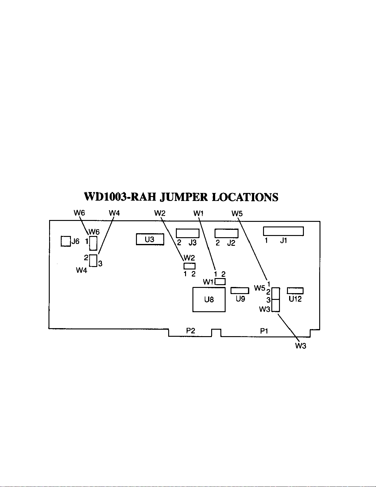
WDl003-RAH JUMPER SETTINGS
JUMPER PIN CONNECTS DESCRIPTION
W1 1-2 Standard factory setting. Status read is latched. Used for IBM
Personal Computer AT if Winchester activity LED is connected to
J6.
OPEN Status read is not latched. Activity LED turns on during drive
access. W5 must be jumpered 2 to 3. Used for Compaq hosts.
W2 OPEN Standard factory setting. Selects primary addresses, 1F0 through
1F7 and 3F0 through 3F7 hex. Do not modify the primary address
jumper unless your BIOS operating system is configured to accept
more than two hard disk drives.
1-2 Selects secondary addresses, 170 through 177 and 370 through
377 hex.
W3 OPEN
1-2
W4 2-3 Standard factory setting. No translation for drive 0.
1-2 Enables translation for drive 0. Translation is only available for
W5 2-3 Standard factory setting. WG and drive select lines only enabled
1-2 WG and drive select lines are disabled during power up reset and
W6 2-3 Standard factory setting. No translation for drive 1.
1-2 Enables translation for drive 1. Translation is only available for
This configuration used with WD11C00C-22 at board location US
or if W5 is jumpered 1 to 2. Required only on early units with
WD11C00-22 at board location U8 and W5 is jumpered 1 to 2. DO
NOT JUMPER WITH THE WDl1C00C-22 INSTALLED.
615 cylinders and four headed drives. In translation mode, the
controller translates the 26 physical sectors per track into 17
sectors. The extra sectors are "translated" into logical heads. To
use the translation mode, select through the Setup program a 615
cylinder and six head drive type. (This is drive type three for IBM
Personal Computer AT users. Not all AT-compatible systems use
the same drive tables as IBM.) This configuration must be used
when running an operating system or application program which
requires a 17 sector per track disk drive.
when drive is accessed. This configuration also provides power up
and down protection.
when + 5V power supply drops below approximately +4.1 5V.
615 cylinders and four headed drives. In translation mode, the
controller translates the 26 physical sectors per track into 17
sectors. The extra sectors are "translated" into logical heads. To
use the translation mode, select through the Setup program a 615
cylinder and six head drive type. (This is drive type three for IBM
Personal Computer AT users. Not all AT-compatible systems use
the same drive tables as IBM.) This configuration must be used
when running an operating system or application program which
requires a 17 sector per track disk drive.
Page 4

Hardware Installation
This section describes installation of your hardware. If the disk drive(s) is (are) installed
internally, it is best to locate the controller in the closest available expansion slot relative to the
drive.
CAUTION
Handle the controller board by the ends of the boar d. So me of t he chips are static sensitive
and damage may occur if the board is incorrectly handled.
Furthermore, do NOT under any circumstances connect an RLL controller to an MFM
drive. Refer to “If You Have a Problem” section for further information.
Page 5

WD10035-RAH JUMPER SETTINGS
JUMPER PIN CONNECTS DESCRIPTION
W1 1-2
OPEN
W2 OPEN
1-2
Standard factory setting. Status read is latched. Used for IBM Personal Computer AT
if Winchester activity LED is connected to J6.
Status read is not latched. Activity LED turns on during drive access. W5 must be
jumpered 2 to 3. Used for Compaq hosts.
Standard factory setting. Selects primary addresses, 1F0 through 1F7 and 3F0 through
3F7 hex. Do not modify the primary address jumper unless your BIOS operating
system is configured to accept more than two hard disk drives.
Selects secondary addresses, 170 through 177 and 370 through 377 hex.
W3
W4 1-2
2-3
W5 2-3
1-2
W6 1-2
2-3
W7 1-2
3-4
1-3
2-4
Applicable to the WD1003-RAH. Eliminated by design and artwork changes to the
WD1003S-RAH.
Standard factory setting. No translation for drive 0.
Enables translation for drive 0. Translation is only available for 615 cylinders and four
headed drives. In translation mode, the controller translates the 26 physical sectors per
track into 17 sectors. The extra sectors are "translated" into logical heads. To use the
translation mode, select through the Setup program a 615 cylinder and six head drive
type. (This is drive type three for IBM Personal Computer AT users. Not all ATcompatible systems use the same drive tables as IBM.) This configuration must be
used when running an operating system or application program which requires a 17
sector per track disk drive.
Standard factory setting. WG and drive select lines only enabled when drive is
accessed. This configuration also provides power up and down protection.
WG and drive select lines are disabled during power up reset and when + 5V power
supply drops below approximately +4.1 5V.
Standard factory setting. No translation for drive 1.
Enables translation for drive 1. Translation is only available for 615 cylinders and four
headed drives. In translation mode, the controller translates the 26 physical sectors per
track into 17 sectors. The extra sectors are "translated" into logical heads. To use the
translation mode, select through the Setup program a 615 cylinder and six head drive
type. (This is drive type three for IBM Personal Computer AT users. Not all ATcompatible systems use the same drive tables as IBM.) This configuration must be
used when running an operating system or application program which requires a 17
sector per track disk drive.
Standard factory setting. Controller operates with daisy-chained drive(s). Both can be
daisy-chained from J1 or drive 0 can be connected to J1 and drive 1 can be connected
to J5. For daisy-chained operation, set the drive select jumpers on the first drive for
drive 0 and on the second drive for drive 1.
Controller operates with parallel connected drives. Attach drive 1 control connector to
J1.
Attach drive 0 control connector to J5. For parallel operation, set the drive select
jumpers on both drives for drive 0.
W8 1-2
2-3
Standard factory configuration. Ties input high
Enables seek to landing zone (cylinder 663) on any seek to a cylinder greater than
615. Used only for 615 cylinder drives. This jumper also changes step rate 0 (24 µsec)
to step rate 15 (11 µsec).
.
Page 6

Only verify the jumper settings in step 1. Modification of the standard factory jumper settings
on the controller is rarely necessary. Modify jumpers only under the direction of a qualified
individual, i.e. your dealer.
1.Verify controller jumper settings. Refer to pages 1 through 9 for jumper setting
information.
2. Verify terminat ion on last drive. Verify proper setting of drive select switches on drive,
i.e. set the drive select switches for drive select 1 or 2. Refer to your drive owner's
manual for information about proper drive termination and select switches.
3. Remove the bla nk expansion slot bracke t. Put the bracke t away and save it for possible
future use. The screw will be used to hold the new controller board in place.
NOTE
Verify that the cable c onnectors mate properly with the board connectors. This is easily
done by checking that pin 1 on the cable mates with pin 1 on the connector. Pin 1 is clearly
marked on the board's connectors. Pin 1 on the cables is usually on the color coded side.
4. WD1003-RAH: Attach 34-pin control connector to J1
WD10035-RAH: Attach 34-pin control connector to J 1 if W7 is set for daisy-chained
operation.
NOTE
Normally, daisy-chaining implies that two drives connect to the same connector. That is
still true with the WDl0035-RAH. However, it i s possible to connect the second drive to J5.
Regardless of the connection, one drive must be configured as drive 0 and the other drive
must be configured as drive 1.
Attach drive 1 's 34-pin connector to J 1 and drive 0's 34-pin connector to J5 if W7 is set
for parallel connection. (Refer to Tabl e 2 for further information.) Set the drive select
jumpers on both drives to drive 0 if W7 configures the controller for parallel connection.
WDl003-RA2: Attach 34-pin control connector J5.
WDl003A-RA2: Attach 34-pin control connector to J4.
5. Connect control cable(s) to drive(s).
6. WD1003-RAH WDl003S-RAH: Attach drive 0's 20-pin data connector to J2.
Page 7

WD1003-RA2: Attach drive 0's 20-pin data connector to J4.
WD1003A-RA2: Attach drive 0's 20-pin data connector to J3.
7. WD1003-RAH
WD1003S-RAH
WD1003-RA2: Attach drive 1's data connector to J3.
WD1003A-RA2: Attach drive l's data connector to J2.
8. Connect data cables to drives.
9. WD1003-RA2: Attach 34-pin floppy cable connector to J1.
WD1003A-RA2: Attach 34-pin floppy cable connector to J5.
10. WD1003-RAH
WD1003S-RAH
WD1003-RA2: Attach Winchester activity LED connector to J6.
WD1003A-RA2: Attach Winchester activity LED to Jl.
11. Install the controller board into the expansion slot. Make sure that the board is seated
properly by pressing down on both ends of the board. Secure the boa rd wit h the bra cket
screw.
12. Remove or disable any other floppy controller in your system if you are installing a
WD1003RA2 or WDl003A-RA2. It is NOT possible to disabl e the floppy cont roller on
the WD1003-RA2 or WD 1003A-RA2.
Page 8

NOTE (For WD1003-RA2 only)
Translation
translation program converts the drive's 26 physical sectors per track to 17 sectors per track. The extra sectors are
"translated" into logical heads. To use the translation mode, select through the Setup program a 615 cylinder and six
head drive type. (This is drive type three for IBM Personal Computer AT users. Not all AT-compatible systems use the
same drive tables as IBM.) This configuration must be used when running an operating system, application program, or
system BIOS that requires a 17 sector per track disk drive.
only available with F001 controllers. F000 controllers operate in non-translation mode only. F001's
is
WD1003-RA2 JUMPER SETTINGS
JUMPER PIN CONNECTS DESCRIPTION
E1
E2
E3
E4
E5
E6
E7
E8
E9
E2-E3 Standard factory setting. Selects primary addresses, 1F0 through
for the hard disk controller. Do not modify the primary address jumper
unless your operating system is configured to accept more than two hard
disk drives. Also verify that ES and E6 are connected if E2 and E3 are
jumpered.
El-E2 Selects secondary addresses, 170 through 177 hex, for the hard disk
controller. Also verify that E4 and ES are connected if El and E2 are
jumpered.
E5-E6 Standard factory setting. Selects primary addresses, 3F0 through 3F7 hex,
for the floppy disk controller. Do not modify the primary address jumper
unless your operating system is configured to accept more than two hard
disk drives. Also verify that E2 and E3 are connected if ES and E6 are
jumpered.
E4-E5 Selects secondary addresses, 370 through 377 hex, for the floppy disk
controller. Also verify that El and E2 are connected if E4 and ES are
jumpered.
E7-E8
E8-E9
Standard factory setting. Supports 300 or 360
Selects dual speed spindle floppy disk drives.
floppy disk drives.
RPM
1F7
hex,
Page 9

Page 10

WD1003A-RA2 JUMPER SETTINGS
JUMPER PIN CONNECTS DESCRIPTION
W1 1-2
2-3
W2 1-2 Standard factory setting. No translation for drive 0.
OPEN
1-2
CLOSED
W2 3-4 Standard factory setting. No translation for drive 1.
OPEN
CLOSED Enables translation for drive 1.
This configuration used with a WDllC00C-22 at board location Ul6.
Required only on early units with WDl lC00-22 at board location U8 and
W5 is jumpered 1 to 2. DO NOT JUMPER WITH WDllC00C-22
INSTALLED.
Enables translation for drive 0. Translation is only available for 615
cylinders and four headed drives. In translation mode, the controller
translates the 26 physical sectors per track into 17 sectors. The extra
sectors are "translated" into logical heads. To use the translation mode,
select through the Setup program a 615 cylinder and six head drive type.
(This is drive type three for IBM Personal Computer AT users. Not all
AT-compatible systems use the same drive tables as IBM.) This
configuration must be used when running an operating system or application program which requires a 17 sector per track disk drive.
W3 3-4
1-2
W4 3-5 Standard factory setting. Selects primary addresses, 1F0 through 1F7 hex,
4-6 Standard factory setting. Selects primary addresses, 3F0 through 3F7 hex,
1-3 Selects secondary addresses, 170 through 177 hex, for the hard disk
2-4 Selects secondary addresses, 370 through 377 hex, for the floppy disk
W5 1-2 Standard factory setting. Closed by etch on the solder side of the board.
2-3 Carefully cut etch and jumper to operate the controller with hard disk
W6 Removed from final release.
W7 2-3
1-2
Standard factory setting. DO NOT OPEN.
Standard factory setting. DO NOT OPEN.
for the hard disk controller. Do not modify the primary address jumper
unless your operating system is configured to accept more than two hard
disk drives. Also verify that W4 positions 4 and 6 are connected if 3 and
5 are jumpered.
for the floppy disk controller. Do not modify the primary address jumper
unless your operating system is configured to accept more than two hard
disk drives. Also verify that W4 3 and 5 are connected if 4 and 6 are
jumpered.
controller. Also verify that W4 2 and 4 are connected if 1 and 3 are
jumpered.
controller. Also verify that W4 1 and 3 are connected if W4 2 and 4 are
jumpered.
Configures the board to control drives with a maximum of eight heads or
Reduced Write Current (RWC).
drives having a maximum of 16 heads.
Standard factory setting. Supports 300 or 360
Supports dual speed spindle floppy drives.
floppy disk drives.
RPM
Page 11

Software Installation Instructions
This section contains instructions for preparing (low level format) the drive to be recognized by
the operating system. Formatting the drive uses one of several software programs, the Advanced
Diagnostics (or equivalent in AT compatibles), Disk Manager from Ontra ck Comput er Systems,
or Speedstor 4.02 from Storage Dimensions. Use of the programs depends on the controller
configuration. Configuring the controller to use the translation feature requires running the
Advanced Diagnostics program, Setup. Setup defines the drive type for the system and low level
formats the drive. Without translation, Advanced Diagnostics can low level format the drive if
the system BIOS recognizes the 26 sector RLL format. (Storage Dimensions' Speedstor 286
BIOS is a replacement set of BIOS ROMs for the AT system board.) Run the DOS programs,
FORMAT and FDISK, after performing the low level format, regardless of the controller
configuration.
Software Installation Instructions for Non-Translation Mode
NOTE
Formatting disk media with this operational mode requires a host system with a 26 sector
BIOS. If the system does not contain a 26 sector BIOS, O ntrack and Storage Dimensions
produc e pro grams t o support t he 26 se ctor RLL dri ves. F or fur ther i nfor mation on these
programs, contact:
Ontrack Computer Systems
6222 Bury Drive
Eden Prairie, Minnesota 55344
(612) 937-1107
Storage Dimensions
14127 Capri Drive, Suite 1
Los Gatos, California 95030
(408) 370-3304
The Disk Manager and Speedstor products are the only products that have been tested by
Western Digital at this publication date. Both work well, providing full usage of the RLL
capacities. However, these are not the only alternatives for removing system limitations.
Contact your dealer for further information.
1. Boot the system with the Advanced Diagnostics. Define the drive type(s)
through the Setup option. After defining the drive types, run System
Checkout. Enter 0 after the "Select the action desired" prompt.
2. Select fixed disk option 17.
3. Select the Format Menu from the Fixed Disk Diagnostic Menu.
4. Unconditionally format the drive with the Format Selection Menu.
5. Enter bad block in the Defect Entry table.
Page 12

6. Formatting begins. After formatting the drive, press "ENTER". Boot and
operate the system normally.
If you require further information or other technical support, please contact your authorized
dealer.
Software Installation Instructions for Translation Mode
1. Insert your system diagnostic diskette (or equivalent) in drive A.
2. Turn on the system power.
3. Boot diagnostic and select Setup option.
CAUTION
Avoid system damage by consulting your Te c hnic al Re ference Manual to ensure that your
drive type is supported by your host BIOS ROM drive tables. Not all AT-compatibles share
the same drive tables as IBM.
4. Set up the system for the proper configuration of diskette and fixed drives (drive
type 3 for IBM), base memory size, expansion memory size, and display.
CAUTION
The following step requires execution of low level formatting. Formatting a dri ve destroys
any data on the drive. If your drive contains useful data, backup the dr iv e be fo re e xe cut io n
of the low level format. Use of Advanced Diagnostics (or similar program) is necessary
since the controllers contain no on-board BIOS ROM.
5. After performing Setup, execute a low level format using the Advanced Diagnostics
diskette. Follow the menu and reference manual instructions.
6. Load and execute the FDISK and FORMAT programs. Follow the menu and
reference manual instructions.
Page 13

If You Have a Problem. . .
Eliminate the obvious fault causing problems; i.e., reversed cables, improper drive selection or
termi nation, etc. This section lists some of the common problems and possible solutions
encountered when installing a drive controller.
PROBLEM: 1790 Disk 0 Error.
CAUSE: No lo w l e ve l format on hard disk. Wrong drive type selected. Not enough
drive power. Bad cables. Improper drive selection or termination.
PROBLEM: Drive does not partition.
CAUSE: Check drive types. Note that drive t ypes for the AT and AT-compatibles
differ.
PROBLEM: "Error Reading Fixed Disk" appears when booting from hard drive.
CAUSE: DOS partition not active.
PROBLEM: Winchester activity LED continuously lit.
CAUSE: No problem! Drive LED selected for latched mode.
PROBLEM: For systems with two drives, both Winchester activity LEDs light at the
same time.
CAUSE: Improper drive selection or termination. Inspect the drive cables. If the
data cables are straight, then set drive C's drive select switches for drive
select 1 and drive D's drive select switches for drive select 2. If the data
cables have a twist, set both drives' select switches for drive select 2.
Consult your drive manuals or dealer for drive switch settings. Finally,
under no circ umstanc e, use twiste d floppy ca bles for the W inche ster drive .
Floppy and Winchester drive interface connections differ significantly.
PROBLEM: Slow and inefficient operation.
CAUSE: The biggest culprit for this problem is an incorrect interleave factor.
Therefore, some experimentation with the interleave factor may be
necessary. (Refe r to the format instructions for setting interleave factor.)
Interleave factors are very dependent on the host operating system and
application.
Page 14

PROBLEM: Controller does not format a Seagate ST225 to 30 MB.
CAUSE: The ST225 is a 20 MB MFM drive. The ST238 is a 30 MB RLL drive . This
is a good time to point out the differences between RLL and Modified
Frequency Modulation (MFM) disk drives and controllers. First, RLL
equipment is able to record 50% more data on the drive. Second, RLL
drives must be physically formatted with 26 sectors because of the greater
data density. This leads to an important point:
DO NOT UNDER ANY CIRCUMSTANCES CONNECT A RLL
CONTROLLER TO AN MFM DRIVE!
RLL controllers physically format any attach drive into 26 sectors.
Therefore, the RLL controller squishes 26 sectors onto a drive designed for
17 sectors. Squishing the RLL data onto an MFM drive re sul ts i n c orrupte d
data, to say the least. Finally, the chip sets on RLL and MFM cont rollers
significantly differ as a result of the first and second points.
 Loading...