


WD Caviar® SE
EIDE Hard Drive
Quick Install Guide
Desktop Internal
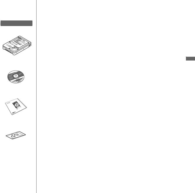
Kit Contents
WD Hard Drive
Utilities and software CD
Documentation
Mounting Screws and
Jumper Shunt
This document was designed to aid in the quick installation of your new WD EIDE hard drive. For further information regarding the installation and use of your drive, visit our website at support.wdc.com.
Compatibility
Windows® XP (SP 1 or higher needed for drives >137 GB) Windows 2000 (SP 3 or higher needed for drives >137 GB)
Windows Me and Windows 98SE (may require an Ultra ATA controller card)
Mac® OS X v10.2 or later requires a Mac-compatible ATA controller card (for drives larger than 137 GB)
Note: Compatibility may vary depending on user’s hardware configuration and operating system.
Unpacking & Drive Handling Information
WD hard drives are precision instruments and should be handled with care during unpacking and installation. Hard drives can be damaged by rough handling, shock and vibration, or electrostatic discharge (ESD). Be aware of the following precautions:
•This product contains no user-serviceable parts; refer servicing to WD authorized personnel only.
•Do not unpack your hard drive until you are ready to install it. Your hard drive is packaged in an anti-static bag.
•To avoid ESD problems, ground yourself by touching the metal chassis of the computer before handling the hard drive. Articles of clothing generate static electricity. Do not allow clothing to come in direct contact with the hard drive or circuit board components.
•Handle the hard drive by its sides only. Avoid touching the circuit board components on the bottom of the hard drive.
•Do not drop, shake, or knock down the hard drive.
•Do not stack hard drives or stand your WD hard drive on its edge.
Operating System Information
Installing Your New WD Hard Drive as an Upgrade From a Previously Installed Hard Drive
To ensure the optimal settings for your drive configuration, we recommend you run the Installation Tutorial in the Windows version of Data Lifeguard Tools™ prior to the hardware installation. Data Lifeguard Tools for Windows will generate your custom installation instructions based on the configuration you choose. For more information on using Data Lifeguard Tools, visit our website at
support.wdc.com.
EN
Windows XP (Service Pack 1 or higher) and 2000 (Service Pack 3 or higher)
If you are running one of these operating systems, run the Data Lifeguard Tools Installation Tutorial, carefully following the on-screen instructions to set up your larger than 137 GB hard drive without a controller card.
Windows 98SE and Windows Me
If your system does not support 48-bit Logical Block Addressing (LBA), WD recommends installing an Ultra ATA controller card to access the full capacity of your hard drive greater than 137 GB. Make sure that your system BIOS supports the card and that its drivers have been properly installed prior to connecting the hard drive. You can purchase an Ultra ATA/100 PCI controller card at the WD Online store at store.wdc.com (U.S.A. only) or your local computer retailer. For more information, visit our website at support.wdc.com.
Alternate Solution
Intel® offers drivers for certain chipsets which provide BIOS support for the full capacity of drives larger than 137 GB. Contact your motherboard or system manufacturer for compatibility and installation instructions.
1. Before Getting Started
1.Gather these materials and tools: WD hard drive kit; standard 40-pin, 80-conductor cable; computer system manual; operating system manual and installation diskette/CD; Phillips and flat-blade screwdrivers.
2.Before performing any hardware installation, back up your existing data.
3.Before handling the hard drive or any other components, discharge static electricity by touching the metal chassis of your computer or by using an anti-static wrist strap.
4.Record your WD hard drive serial number, model number, and date code.
5.Power off the computer and unplug the power cord.
6.Remove the system cover (refer to your system manual for instructions).
-1-

Figure 1
40-pin IDE connector
|
Jumper block |
Jumper shunt |
Power supply connector |
|
|
Single |
Cable Select (Default Setting) |
|
|
|
|
|
|
Dual (Master) |
Dual (Slave) |
||||
|
|
|
|
|
|
|
|
|
|
|
|
|
|
|
|
|
|
Figure 2
|
Gray 40-pin connector |
|
|
Blue 40-pin |
|
|
Black 40-pin |
|
|
connector |
|
connector |
|
|
|
SYSTEM |
SECONDARY DRIVE |
PRIMARY DRIVE |
|
|
(SLAVE) |
|
(MASTER) |
Figure 3 |
|
|
|
Pin 1 |
|
IDE |
|
|
Motherboard |
|
|
|
Interface cable |
interface |
|
|
cable |
|
|
|
from hard drive |
|
|
|
|
|
Power |
|
|
|
connector |
|
|
|
Power supply cable |
Figure 4

 Mounting frame
2. Set the Jumpers
WD EIDE hard drives have a 10-pin jumper block located next to the 40-pin IDE connector on the hard drive. Jumper the drive according to your desired configuration (i.e., Cable Select, Master/Slave, or Single). Refer to the illustration on the left (Figure 1) for reference.
A. Cable Select
Cable Select is the default setting for WD EIDE hard drives and requires a standard 40-pin, 80-conductor cable (not included). If your system supports Cable Select, there is no need to reposition the jumper shunt on the drive. If you are installing your new WD hard drive with an existing IDE drive on the cable, make sure that the other drive is also jumpered as Cable Select. If your system does not support Cable Select or if you are uncertain, use the Single or Master/Slave configuration.
Note: Cable Select mode is not supported by Macintosh’s built-in IDE/ATA controller. You must use the Master/Slave jumper setting.
B. Standard Jumper Settings (Master/Slave or Single Configuration)
1.If installing your new WD hard drive as the only device on the cable, use the Single setting (no jumper shunt required).
2.If installing your new WD hard drive as the Master device on the cable with two IDE drives, use the Master setting.
3.If installing your new WD hard drive as a secondary device on the cable, use the Slave setting.
3. Install the Hard Drive
Important: Your new WD hard drive must be installed using a standard 40-pin, 80-conductor IDE interface cable.
Note: Installation instructions will vary depending on your drive configuration. Carefully follow the appropriate procedure that corresponds to your drive configuration.
1.If installing the hard drive as the only device on the cable, connect the black connector of the IDE interface cable to the drive and the blue end of the cable to the IDE connector on the motherboard.
Proceed to step 3.
2.If installing two drives on the same IDE cable,
a.Jumper the bootable drive as Master and the other drive as Slave; then connect the Master drive to the black connector of the IDE interface cable and the Slave drive to the gray connector.
b.Connect the blue end of the IDE interface cable to the IDE connector on the motherboard (Figure 2).
3.Attach the power supply cable to the 4-pin power connector on the drive (Figure 3).
4.Slide the hard drive into an available 3.5-inch drive bay and secure the drive with the four mounting screws provided (two on each side). For proper grounding, use screws in the hole positions as shown (Figure 4).
5.Verify all cable connections. Replace and secure the system cover. Reconnect the power cord and power on the computer.
-2-
 Loading...